Preprint
Article

Excess Conductivity Analysis of an YBCO Foam Strut and Its Microstructure

Altmetrics

Downloads

117

Views

45

Comments

0

A peer-reviewed article of this preprint also exists.

Submitted:

29 December 2023

Posted:

03 January 2024

You are already at the latest version

Alerts
Abstract
Struts of a superconducting YBa2Cu3Oy (YBCO) foam prepared by the infiltration growth method on the base of commercial polyurethane foams were extracted from the bulk, and thoroughly characterized concerning the microstructure and the magnetoresistance, measured by the four-point technique. Optical microscopy, electron microscopy, electron backscatter diffraction and atomic force microscopy observations indicate an unique microstructure of the foam struts which shows a large amount of tiny Y2BaCuO5 (Y-211) particles (with diameters between 50–100 nm) being enclosed in channel-like grain boundaries between the YBCO grains and an one-of-a-kind surface of the struts covered with Ba3Cu5Oy-particles. The resistance data obtained at temperatures in the range 4.2 K ≤T≤ 150 K (applied magnetic fields ranging from 0 to 7 T) were analyzed in the framework of the fluctuation-induced conductivity (FIC) approach using the Aslamazov-Larkin model. The resulting FIC curves reveal the presence of five distinct fluctuation regimes, namely, the short-wave (SWF), one-dimensional (1D), two-dimensional (2D), three-dimensional (3D), and critical (CR) fluctuation domains. The analysis of the FIC data enable the coherence length in the direction of the c-axis at zero-temperature (ξc(0)), the lower and upper critical magnetic fields (Bc1, Bc2), the critical current density at T= 0 K (Jc(0)) and several other parameters describing the the material’s superconducting properties to be determined. The present data reveal that the minuscule Y-211 particles found along the YBCO grain boundaries alter the excess conductivity and the fluctuation behavior as compared to conventional YBCO samples, leading to a quite high value for Jc(0) for a sample without added flux pinning centers.
Keywords: 
Subject: Physical Sciences  -   Condensed Matter Physics

1. Introduction

Open-cell, superconducting YBa 2 Cu 3 O y (YBCO or Y-123) foams are a very interesting type of superconducting material for several possible applications, e.g., for fault-current limiters or space applications [1,2,3,4], as the porosity of the open-cell foams brings out several advantages over conventional, bulk superconducting samples. This is manifested in an effective cooling process, an easy and quick oxygenation procedure and a low sample weight. The special properties of (nano-)porous and foam-type superconducting samples were recently reviewed in Refs. [5,6].
The superconducting YBCO foam samples are fabricated starting from commercial polyurethane foams, forming firstly sintered, ceramic Y 2 BaCu 5 (Y-211) foams [7,8], which are then transformed to YBCO on the base of the infiltration growth (IG) process [9,10], together with a seed crystal to introduce an overall texture like for bulk YBCO superconductors [11]. This preparation route implies that the resulting microstructure is clearly different from the conventional bulks owing to the infiltrating liquid converting the Y-211 to YBCO. The broken-out foam struts reveal a specific microstructure with numerous tiny Y 2 BaCuO 5 (Y-211) particles with a size of 50-100 nm in diameter, which are embedded in channel-like grain boundary structures between the YBCO grains, which are typically oriented ± 30 off the [001]-direction owing to the 3D arrangement of the struts in the bulk foam sample. Furthermore, several large Y-211 particles prevail in the foam struts. Several details of the microstructure of the YBCO foam struts investigated by means of digital optical microscopy, scanning electron microscopy (SEM), electron backscatter diffraction (EBSD) and atomic force microscopy (AFM) were already presented in former publications [3,12,13], and foam struts broken out from various locations of a large foam sample were measured by SQUID magnetometry, revealing a dependence on the position within the original foam sample [14]. However, the details of the flux pinning in the foam materials are not yet fully understood, so a better knowledge of the flux pinning properties will contribute considerably to further improve the local critical current densities, especially at elevated temperatures like 77 K, i.e., the temperature of liquid nitrogen.
The excess conductivity analysis can provide detailed information on the transition to the superconducting state from temperatures well above T c . The resistivity curves of HTSc materials exhibit a pronounced rounding around the superconducting transition, which is due to the high anisotropy, the short coherence lengths, and the low density of charge carriers [15]. Thus, it becomes possible to probe the fluctuations of the superconducting Cooper pairs in a wide temperature range beyond T c . As result, several microscopic properties of HTSc materials can be accessed experimentally. These microscopic parameters involve the dimensionality of the order parameter, the various cross-over temperatures between the different fluctuation regimes, the coherence length in the direction of the c-axis of the material, and several other parameters describing details of the superconducting state as the upper and lower critical fields, B c 1 , B c 2 , and the critical current density at T = 0 K, J c ( 0 ) could be deduced [15]. Moreover, it is possible to examine different theoretical models of the critical regime near to T c or of the creation mechanism of the Cooper pairs. In the literature, various model approaches such as the Aslamazov-Larkin (AL) model [16], the Lawrence-Doniach (LD) model [17] and the Maki-Thompson (MT) model [18] were introduced to analyze the fluctuation-induced conductivity (FIC). The physics of FIC was extensively discussed in Ref. [19]. The FIC of various HTSc materials was extensively studied by several research groups [15], and most of these studies preferred the AL model as the base approach. For the case of YBCO with the characteristic Cu-O-planes which act as the highways for the Cooper pairs, this layered structure alters the superconducting parameters. Due to this, Lawrence and Doniach extended the AL approach to cover also layered HTSc materials, where the 2D Cu-O planes are coupled by Josephson tunneling. For HTSc materials, the MT contribution was found to be irrelevant [20], and so the AL and LD models are commonly adopted to identify the intrinsic characteristics from the excess conductivity data.
In the present contribution, we performed magnetoresistance measurements in applied magnetic fields up to 7 T using the four-point technique on individual, broken-out foam struts, and performed a detailed analysis of the excess conductivity, which enables to determine several superconducting parameters of the material. These data are then compared to those of other YBCO systems.

2. Experimental procedures

2.1. Sample preparation

To gain a better knowledge of the specific microstructure of a foam strut, the fabrication steps have to be considered. The fabrication route to obtain superconducting YBCO foam samples was developed at RWTH Aachen, Germany [1] and consists of a two subsequent steps:
(i)
The base material employed are polyurethane foams being commercially available. These foams then set the porosity of the final superconducting foam. The base foam is then filled with a slurry of Y-211 powder, dissolved in a mixture of polyvinylalcohol (PVA) and demineralized H 2 O. A ceramic Y-211 foam is obtained by slow heating at 50 K/h to 600 °C and dwelling for 6 h. In this step, the organic materials, PVA and polyurethane, are fully burnt off. To further compact the Y-211 ceramic, the foam is heated to 1150 °C with 100 K/h and kept there for 10 h.
(ii)
In the second step, the ”green” Y-211 foam is transformed into the YBCO superconductor adopting the infiltration growth process [9,10]. Here, a Nd-123 seed crystal placed on top induces an overall texture to the foam sample. As liquid source, a pellet consisting of a 1:1 mixture of Ba- and Cu- oxides (nominal stoichiometry of Ba 3 Cu 5 O y ) and extra Y-123 powder is located below the Y-211 foam. A temperature above the eutectic temperature (1010 °C) is applied causing the liquid phase to infiltrate the 211 foam by capillary action [21]. Finally, in a slow-cooling process the Y-211 foam is completely transformed to the Y-123 phase, which is also accomplishing the necessary oxygen uptake.
Here, it is important to point out that the seed crystal induces an oriented growth of the YBCO phase like in the common YBCO bulks. However, as the foam struts are randomly oriented, the local microstructure of the foam struts strongly depends on their position and orientation in the original foam sample as we will see in the following Section. Another important point to mention here is the fact that the reaction
Y 2 BaCuO 5 + barium cuprate liquids T p YBa 2 Cu 3 O y
to form the Y-123 compound was not optimized with respect to possible flux pinning, so the resulting superconducting YBCO foams are to be considered as pure YBCO materials.

2.2. Microstructure analysis

The sample surfaces for the SEM/EBSD analysis as well as for AFM investigations were mechanically polished using SiO 2 grinding papers. Subsequently, the surfaces were polished mechanically using three types of diamond paste (3 μ m, 1 μ m and 1/4 μ m diamonds) on the corresponding polishing cloths. Only pure ethanol was employed as lubricant to avoid surface damage by water. To obtain smooth sample surfaces for EBSD and AFM, Struers OP-S solution (colloidal silica, particles with 40 nm in diameter) was used for about 10 min. A detailed description of our sample surface preparation steps applied was published in Ref. [22].
A field emission scanning electron microscope (JEOL 7600 F) as well as a JEOL 7000F SEM microscope (20 kV operating voltage, 10 mm working distance) were employed to obtain SEM images of the foam and the foam struts. EDX analysis was conducted using a EDAX ZAF system with a SUTW sapphire detector. EBSD analysis (standard configuration, i.e., reflection mode) on the foam struts was carried out in a JEOL 7000F SEM microscope equipped with a TSL (TexSEM Labs, UT [23]) analysis unit. A maximum voltage of 15 kV was applied to generate the Kikuchi patterns [24]. A DigiView camera system was employed to record all information. To enable the crystallographic orientation mapping, a surface area was selected to set the frame for scanning the electron beam. For indexation and analysis of the resulting Kikuchi patterns, Orientation Imaging Microscopy (OIM) software was used. A step size as low as 50 nm was employed in the automated EBSD scans.
A Keyence VHX-5000 digital optical microscope [25] with a large depth of field and long observation distance (the images presented in Figure 1 were taken with 100× magnification) was employed for optical microscopy. This system enables 3D imaging to be performed by varying the focal depth on a user-preselected range and digital image processing/analysis. This is especially interesting for the foam samples with their high porosity to enable a clear view of the windows and ligaments. The images obtained were subsequently processed using the built-in analysis software for calibration and size measurements.
For AFM as well as scanning tunneling microscopy (STM) in ambient conditions Digital Instruments Nanoscope III and IV controllers have been used in AFM mode and STM mode [26]. To enable a direct comparison and verification of the results, topograhy scans were carried out in contact mode as well as in tapping mode. For the present investigation, micro-machined doped Si-cantilevers (type PPP, Nanoworld Services GmbH, Erlangen, Germany) were used. Additionally, the signal-to-noise ratio in the tapping mode was improved by means of a Q-control unit. Cut Pt/Ir-tips were employed for the STM scans serving for comparison and to exclude effects from the scanning direction.

2.3. Resistance measurements

Resistance was measured in a Physical Property Measurement System (PPMS) with ±9 T applied magnetic field (Quantum Design) using the standard four probe terminal method. Electrical contacts to the foam struts were made by gold wires and silver paste, with an additional baking process at 150 °C to achieve small contact resistivities. Electric currents (1 – 10 mA) were sent through the samples perpendicularly to the field direction in the measurements using a stabilized Keithley 2400 source meter, and the voltages were recorded by a Keithley 2182A nanovoltmeter.

2.4. Excess conductivity

The excess conductivity arises due to thermal fluctuations of the order parameter, ψ , of high-temperature superconducting (HTSc) materials and depends on internal defects in the structure as well on extrinsic properties of the samples such as the grain morphology, the grain coupling, etc.
The excess conductivity, Δ σ , is defined via
Δ σ = 1 ρ ( T ) 1 ρ n ( T ) ,
where ρ ( T ) denotes the measured resistivity and ρ n ( T ) represents the normal state resistivity. According to the Aslamazov and Larkin theory [16], Δ σ above T c ( T c indicates the mean-field temperature defined as the temperature given by the maximum in the d ρ /dT curves) in the mean-field region, which is given by Δ σ = A ϵ λ , where ϵ = ( T T c ) / T c is the reduced temperature and λ denotes the Gaussian critical exponent related to the conduction dimensionality D. In this way, the conductivity exponent λ can assume several distinct values, i.e., 0.33 for dynamic fluctuations ( λ CR ), 0.66 for static critical fluctuations, 0.5 for three-dimensional (3D) fluctuations, 1.0 for two-diemsional (2D) fluctuations, 1.5 for one-dimensional (1D) fluctuations and 3.0 for short-wave fluctuations. A denotes a constant being temperature-independent, defined via
A = e 2 32 ξ c ( 0 ) ( 3 D ) , A = e 2 16 d ( 2 D ) , A = e 2 ξ c ( 0 ) 32 s ( 1 D ) ,
for the 3D-, 2D- and 1D-case. e denotes the electron charge, ξ c ( 0 ) represents the coherence length along the c-axis at T = 0 K, d gives the effective layer thickness of the 2D system and s describes the wire cross-sectional area of the 1D system.
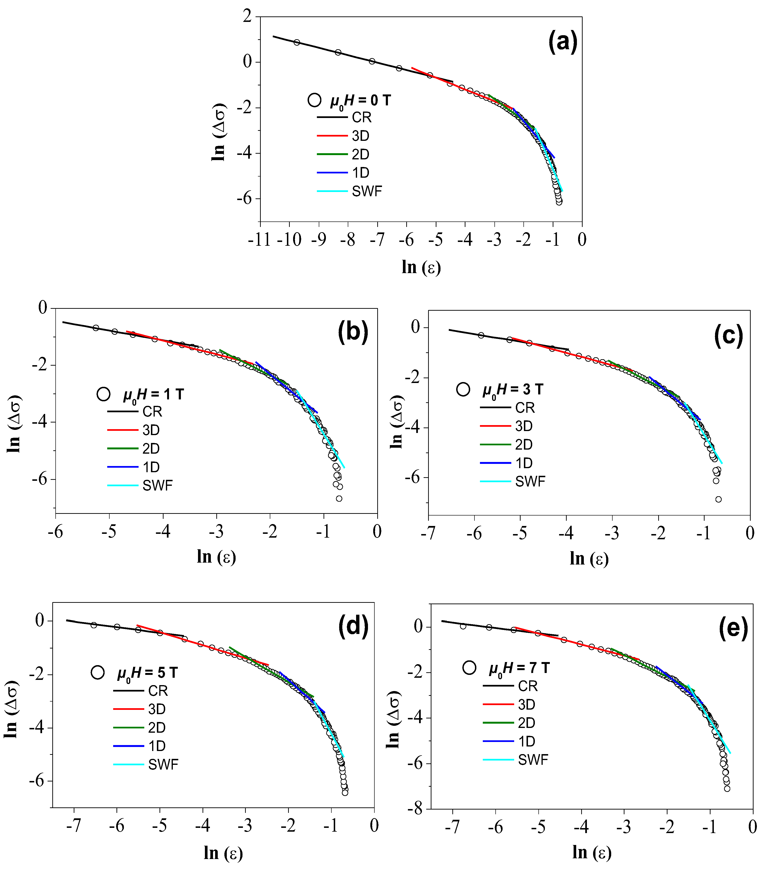
To enable a comparison of the experimental data with the theoretical expression for the fluctuation conductivity, ln ( Δ σ ) versus ln ( ϵ ) can be plotted, allowing the determination of the various fluctuation regimes. In these plots, the various regions are then linearly fitted and the values for the exponents can be determined from the slopes.

3. Results and discussion

3.1. Microstructure

The YBCO foams have a quite specific microstructure due to the applied IG process to form the superconducting material. Figure 1 (a) shows a completely green Y-211 foam after the burn-off of the polyurethane material and sintering. The foam is consists now completely of green Y-211. In Figure 1 (b), a superconducting YBCO foam after the heat treatments is presented. On top, the remnants of the seed crystal can still be seen. Note also the size of the scale bar (1 cm) of this image, which demonstrates that large, superconducting samples can be created in this way, allowing an easy upscaling of the fabrication process [8]. Figure 1 (c) presents a digitally processed 3D-image (Keyence VHX-5000 microscope and software) of the foam windows, struts and ligaments which make up the real foam structure. Figure 1 (d) gives an SEM image of a broken out piece of the foam, exemplifying the 3D-arrangement of the foam struts. A strut like the one marked by the yellow square was employed for the resistance measurements as well as for the following characterization experiments. In Figure 1 (e,f), AFM topography images are presented. Here, one can see several large Y-211 particles sticking out of the surrounding YBCO matrix as Y-211 is clearly harder as compared to YBCO. Also visible are several grain boundaries (GBs) as dark channels between the elongated YBCO grains. The inset to (f) provides a further magnification, revealing a large number of tiny Y-211 particles filling up the channels or grooves between the YBCO grains as marked by white arrows. Figure 1 (g) gives an EBSD image quality (IQ) mapping with the EBSD-detected GBs marked in red (1–5°) and blue (15–180°), and IQ-values ranging between 60 (black) and 750 (white). The dominating light gray color confirms the high image quality of the recorded Kikuchi patterns achieved with the polishing procedure applied here. Figure 1 (h) presents a so-called unique grain color (UGC) mapping of the same area, where neighboring grains are colored in distinctly different colors to highlight the grain arrangement. This image implies that we have several elongated YBCO grains being separated from each other by distinct grain boundaries (grooves), several large Y-211 particles, and a huge amount of tiny Y-211 particles as seen best in the inset to Figure 1 (f). Therefore, we may state here that the foam struts show a grain arrangement which is completely different from more conventional YBCO samples. Finally, the Figure 1i–k present SEM images of the untreated surface of the foam struts. Here, one can see various flow-like structures and many particles on the sample surface which are caused by the capillary flow of the liquid phase during the IG-processing. EDX analysis as performed in Ref. [13] revealed that these particles, which can form either large clusters but also very small particles on the strut surface, are mainly consisting of Ba 3 Cu 5 O y , i.e., the composition of the liquid source during the IG-processing. Up to now, the effect of these Ba 3 Cu 5 O y particles on the flux pinning properties was not yet analyzed in detail, but it is already obvious that such particles may serve as anchor points for flux lines inside the foam strut. Furthermore, we must note here that the large Y-211 particles seen in the EBSD mappings may be obstacles for the current flow in the foam struts with their relatively narrow cross sections. These large Y-211 particles may be leftovers from the previous Y-211 foam, whereas the nanometer-sized Y-211 particles stacked along the YBCO GBs were created during the IG processing. Thus, it will be an useful improvement to better control the size of the Y-211 particles employed in the first step and to make them more reactive in the following IG processing, e.g., by an ultrasound treatment as discussed in Ref. [27].

3.2. Resistance measurements

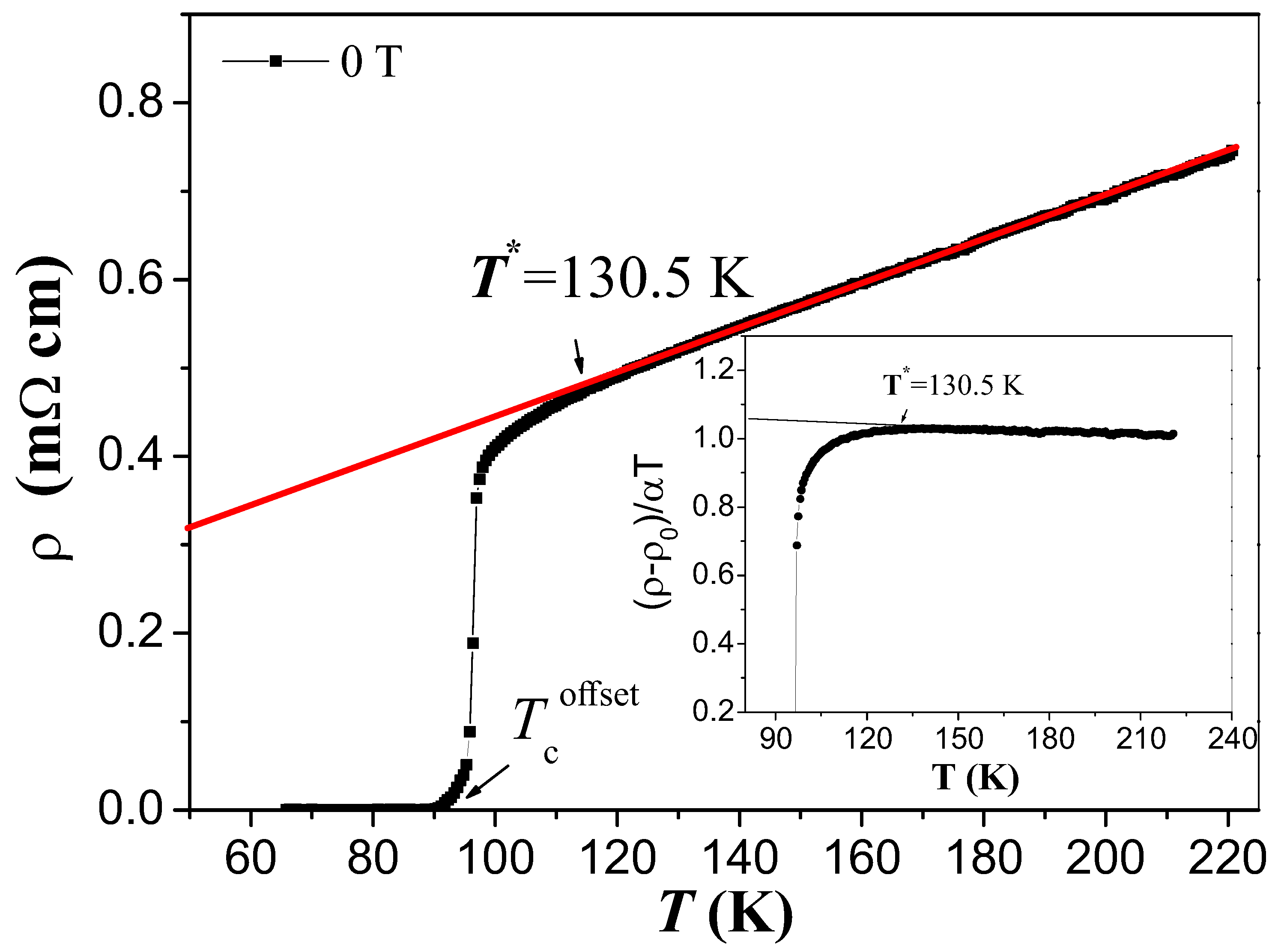
In Figure 2 the measured resistivity ρ ( T ) of the YBCO foam is presented up to 220 K as function of temperature in zero external magnetic field. It was obtained that the prepared YBCO foam sample exhibits a metallic behavior in the normal state followed by a transition to superconducting state at the critical temperature ( T c , offset ). For temperatures beyond T * = 130.5 K and up to room temperature ( T = 300 K), the dependence of ρ ( T ) is found to be linear. In this region, ρ ( T ) is described by a slope α = d ρ / d T = 2.50 μ Ω cm/K. The slope α was computed by approaching the experimental curves and proved the linear behavior of ρ ( T ) with an average-root-square error of 0.009 ± 0.002 in the temperature range considered here.
The temperature T * T c onset is defined as a temperature at which the resistivity curve departs downward from the linear behavior (Figure 2). To determine accurately T * , we used the criterion [ ρ ( T ) ρ 0 ] / α T = 1 [28] (see the inset to Figure 2), where ρ 0 is the intercept of normal-state resistivity nearby the superconducting transition, ρ n ( T ) , with the y-axis. The two methods give approximately the same value of T * = 130.5 K.
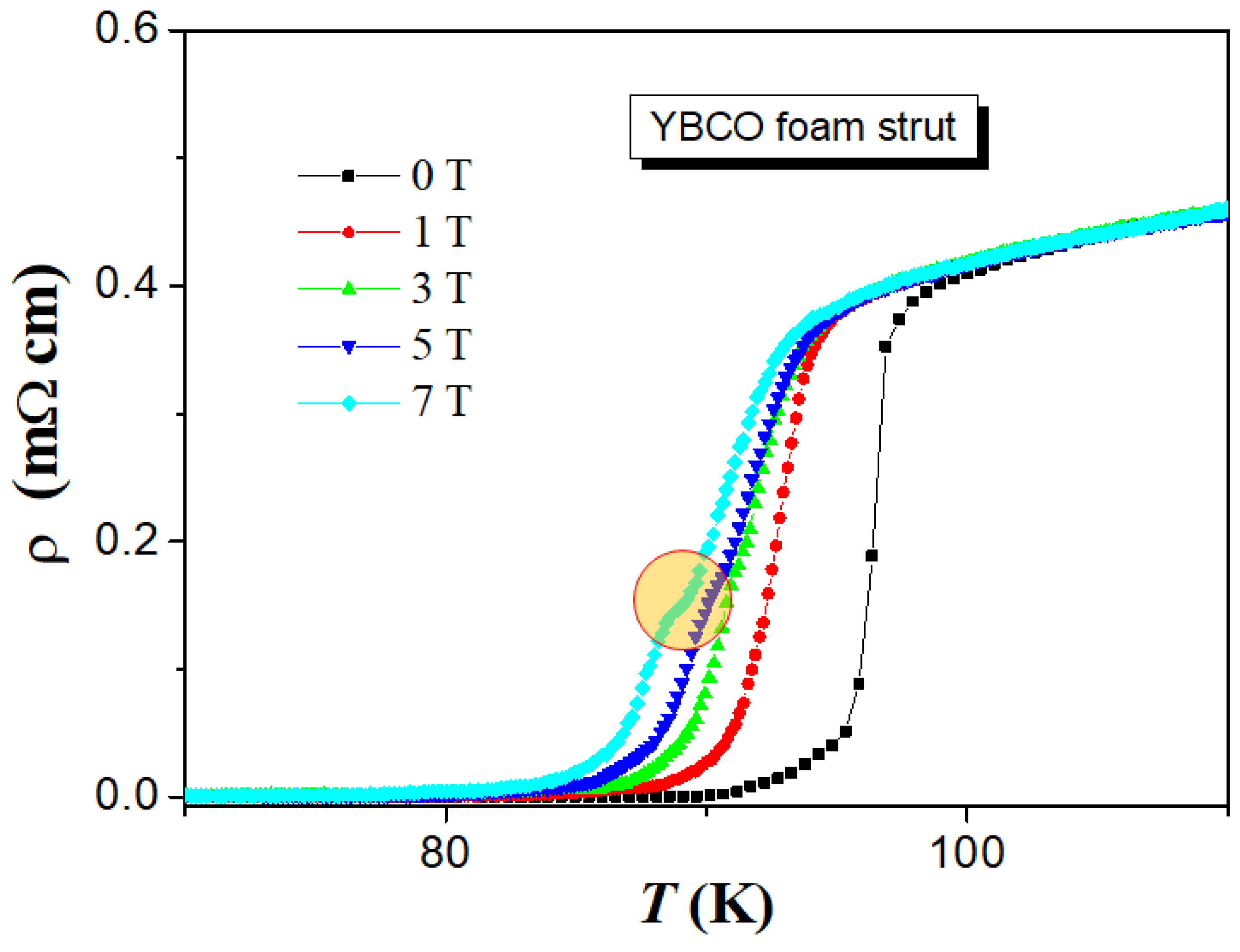
The effect of the applied magnetic field in the range from H a = 0 to 7 T on the temperature dependence of ρ ( T ) is depicted in Figure 3. From these curves, the values of T c onset , T c mid , and T c offset are determined and the results are listed in Table 1. As can be seen, the applied magnetic field considerably widens the resistive transition and reduces T c . The normal state of the YBCO foam sample is also affected. By evaluating each of the curves, both T c onset , and T c are affected and shifted to lower values as H a increases. T c onset is the temperature at which isolated grains enter the superconducting state, while T c describes the temperature at which the superconducting order parameter extends to the intergranular regions and zero resistance arises in the system. In other words, the former is a parameter associated with intra-grain characteristics and the latter is a parameter associated with intergranular characteristics. The decrease of T c offset is more than that of T c onset . This reflects that the applied magnetic field mainly affected the intergranular regions more than that of intra-grain ones, where the field has penetrated in the form of fluxons, resulting in a noticeable decrease of the T c offset values as a result of the motion of fluxons [29]. We further note that at magnetic fields larger than 3 T, a kink appears in the ρ ( T ) -curves (marked by a circle in the figure). This kink may point to a secondary superconducting transition at high fields, but is distinctly different from the giant bump feature seen, e.g., in resistivity measurements of (Nd,Eu,Gd) Ba 2 Cu 3 O y samples [30,31].
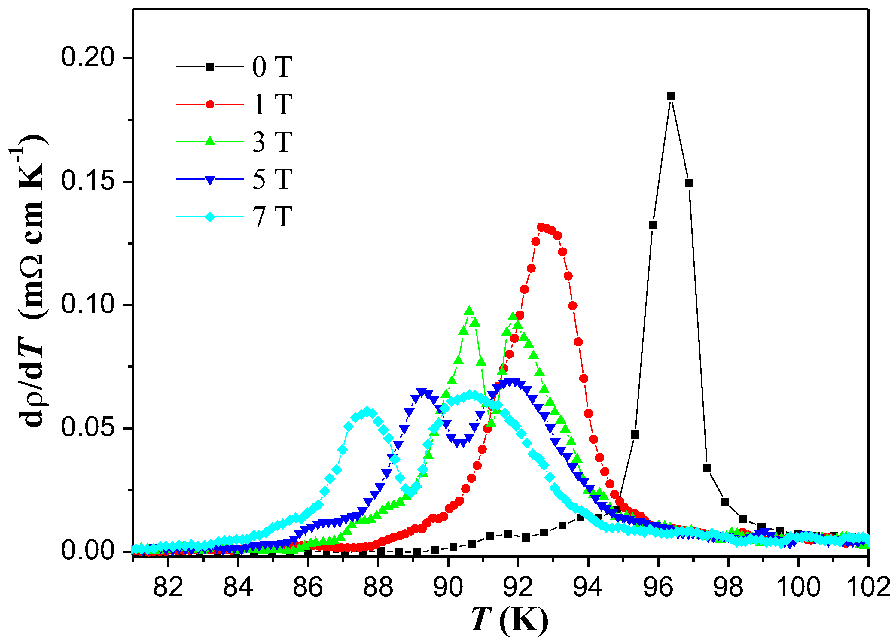
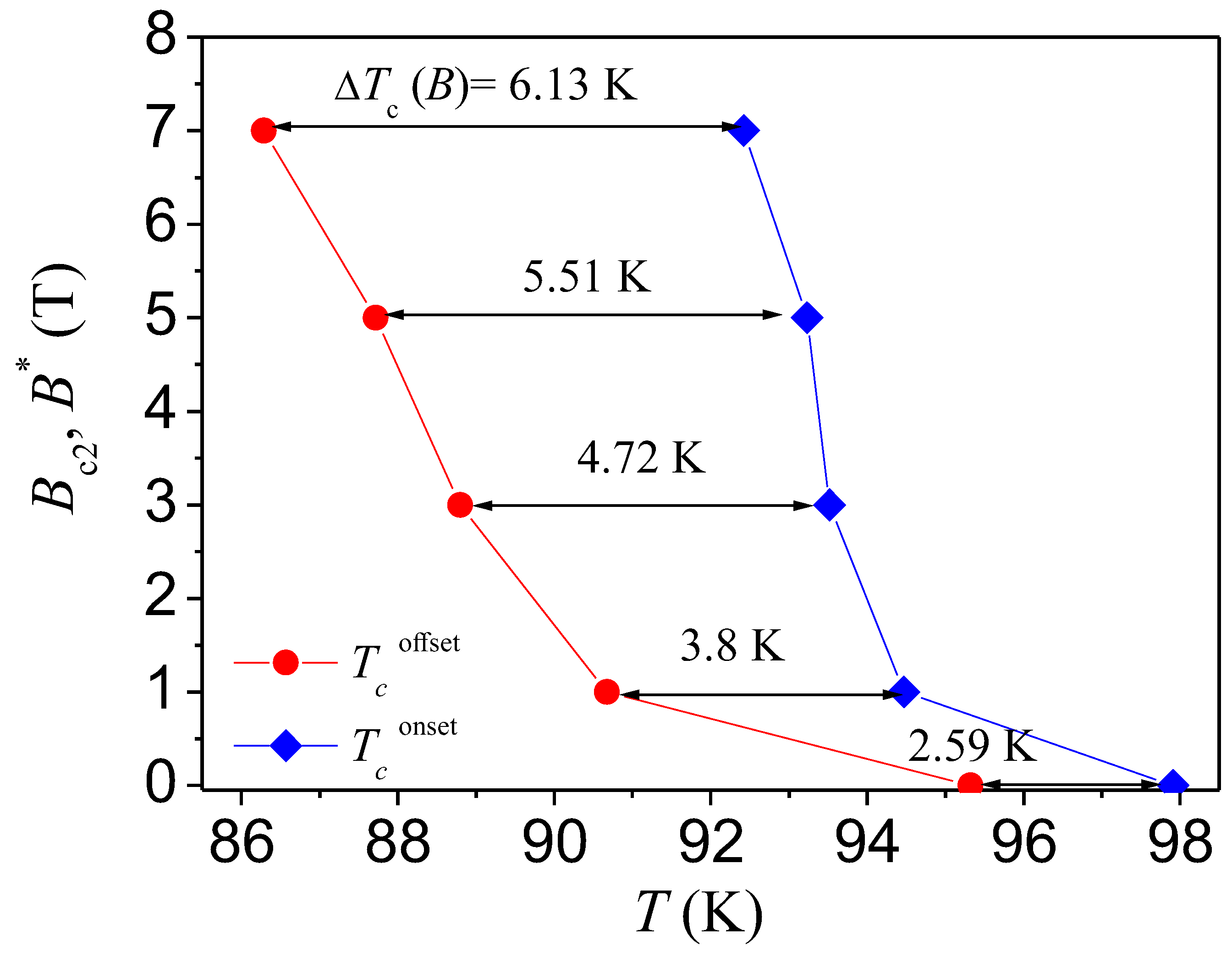
Plots of the derivative of the resistivity, d ρ / d T , versus temperature of the YBCO foam sample in various applied magnetic fields are presented in Figure 4. As described above, a two-stage process for the resistive transition of the YBCO foam struts can be clearly recognized here. The first stage occurs at higher temperatures, where the superconductivity settles into the homogenous and mesoscopic regions of the sample (i.e., the superconducting grains). The second stage arises at lower temperatures where a long-range superconducting state involving zero resistivity is achieved via a percolation-like process (i.e., the activation of weak links between the superconducting grains). For applied magnetic fields of 0 and 1 T, the resistive transition appears as a single peak in d ρ / d T at mid-point temperature T c 1 mid . When the applied magnetic field increases, notable two maxima at T c 1 mid and T c 2 mid were observed. The values of T c 1 mid and T c 2 mid determined from d ρ / d T plots are enlisted in Table 1. A decrease in both T c 1 mid and T c 1 mid values was obtained with the increase of the applied magnetic field. T c onset ( H a ) measurements allow determining the temperature dependence of the upper critical field B c 2 ( T ) (see also Figure 5) [32]. A more significant curve in the B T phase diagram of HTSc (Figure 5) is the irreversibility line separating the vortex liquid state from the vortex glassy state [33]. This line is determined by the temperature dependence of the irreversible magnetic fields B * ( T ) , beyond which the curve of magnetization is reversible where the flowing current forces the fluxons to move [34]. In this regard, energy loss emerges and the supercurrents disappear. From this point of view, the irreversibility field of the HTSc materials plays an analogous role to the upper critical field in conventional superconductors [33,34]. The temperature dependences of both B c 2 ( T ) and B * ( T ) are depicted in Figure 5. Straight lines with arrows on the extremities show the difference between the start T c onset ( H a ) and the T c offset ( H a ) , which was designated as Δ T c ( H a ) . T c onset ( H a ) and the data for T c offset ( H a ) were determined by using the criteria 0.9 ρ n and 0.1 ρ n , respectively [28].

3.3. Excess conductivity

The analysis of excess conductivity has been performed in close vicinity to the critical temperature of the YBCO foam strut sample. The superconducting state with long-range ordering arises at temperatures well beyond the superconducting transition temperature, but a finite probability of formation of Cooper pairs exists in the normal state near the transition during the transport of charge carriers. The formation of Cooper pairs and their interactions with the remaining normal electrons are the cause for the evolution of superconducting fluctuations near to the superconducting transition. When the sample temperature comes close to the transition point, the number of Cooper pairs increases fastly on the cost of normal electrons, which ultimately causes the conductivity of the sample to increase [35]. As consequence, the normal-state resistivity curves tend downwards over the superconductivity transition. The Aslamazov–Larkin model [36] explains the mean-field regime related to the induction of fluctuations as being due to the excess conductivity. The excess conductivity can be denoted by Δ σ and follows a power law as given by Δ σ = A ϵ λ .
Figure 6a–e depict ln Δ σ versus ln ϵ at H = 0, 1, 3, 5, and 7 T applied magnetic fields. Evidently, each plot shows four different regions. The experimental data were compared with the theoretical predictions and the different regions of the plots are linearly fitted. The critical exponent ( λ ) values are determined from the slopes and listed in Table 2. In the vicinity near the mean-field temperatures, the fluctuation conductivity can be described by a power-law critical regime with an exponent around 0.3 at 0, 1, and 3 T. The critical regime was also noticed in other single crystal [37], thin-film [38], and polycrystalline [39] samples. The obtained values are consistent with predictions of the 3D-XY model [40,41]. The critical exponent λ CR achieves the value of 0.2 at 5 and 7 T. The existence of such regimes of fluctuation conductivity characterized by a small exponent was reported in CrO 2 doped YBCO [42], in the Y 0 . 95 Pr 0 . 05 Ba 2 Cu 3 O y compound [43] and in YBCO prepared by planetary ball milling technique [39,44].
This value describes a critical scaling beyond 3D-XY-E and can be explained as revealing a weakly first-order ultimate character of the normal superconducting transition in YBCO samples [45]. At temperatures well above the mean-field temperature, the short-wave fluctuations play a dominant role [46]. In this temperature region, the G-L theory cannot be applied and the excess conductivity shrinks sharply. As the temperature decreases, a crossover between short-wave fluctuations and the mean field region is obtained. The mean-field region, for each applied magnetic field, consists of three different linear parts. At the first part at higher temperature, the conductivity exponent values are close to 1.5, indicating the existence of 1D fluctuations. The emergence of 1D fluctuation conductivity indicates the presence of 1D conducting channels in the superconductor [15]. Similar behavior was previously observed in the case of YBCO embedded with magnetic cobalt ferrite nanoparticles [15]. As the temperature decreases, 2D fluctuation regime was observed which was subsequently transformed to 3D fluctuations at a crossover temperature T LD as the temperatures shifts to the lower values. The different values of crossover temperatures obtained are enlisted in Table 1.
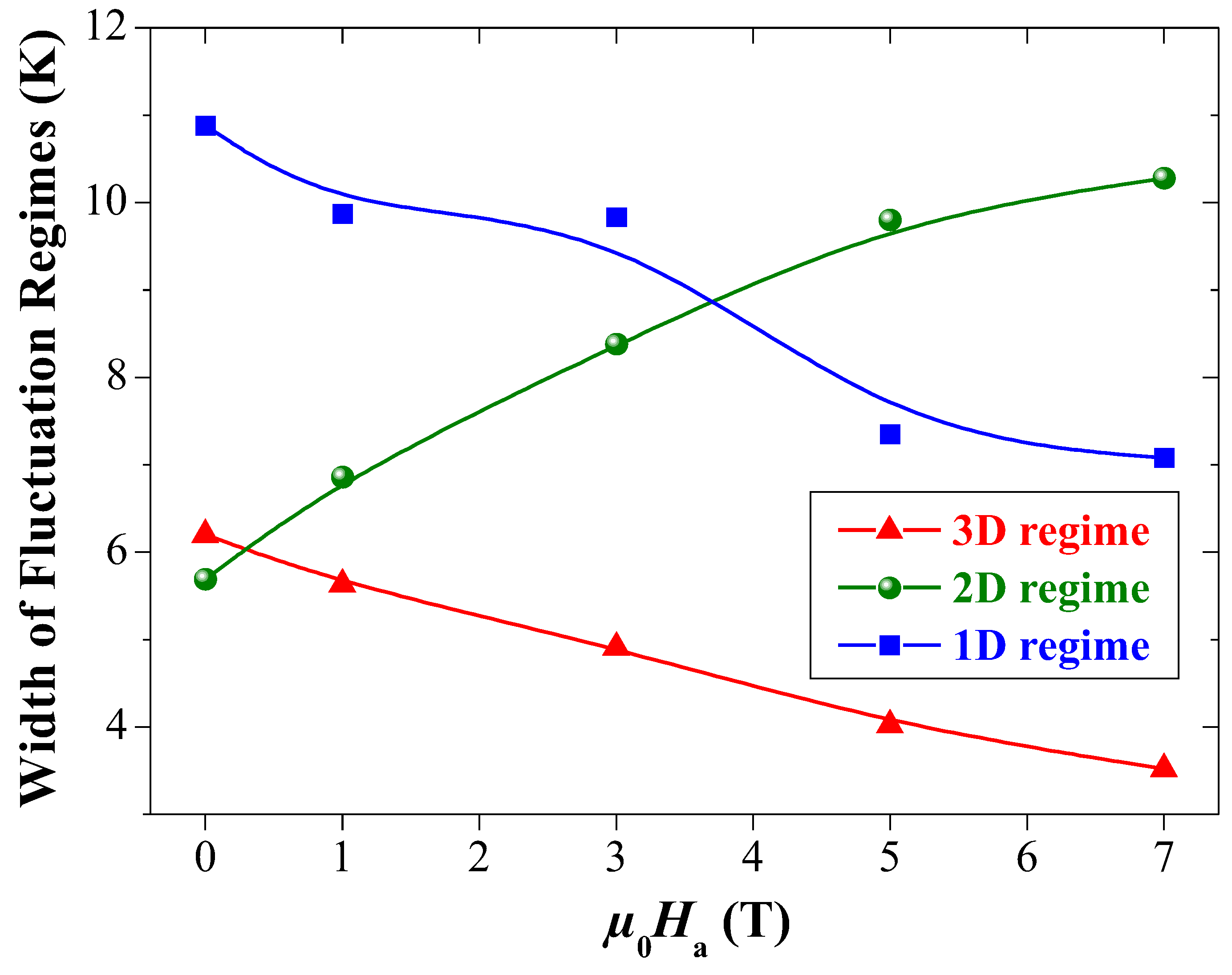
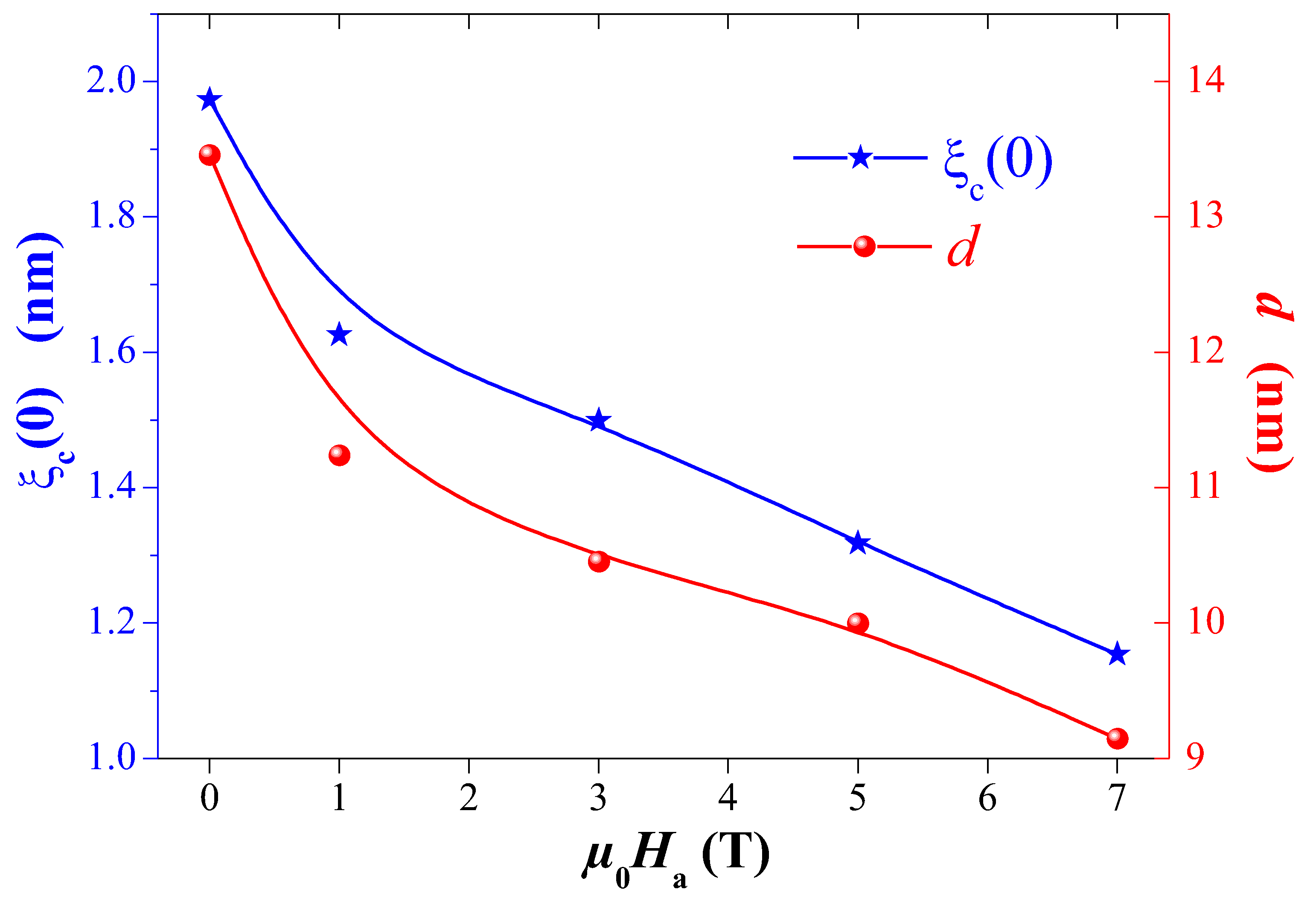
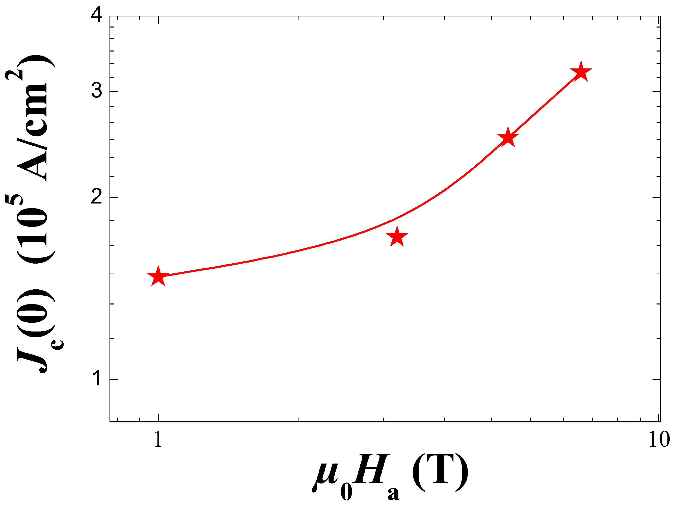
The width of 1D, 2D, and 3D fluctuation regimes are shown in Figure 7. Obviously, the width of the 1D regime decreases with increasing the applied magnetic field, reflecting a destabilization of the conducting charge strips in YBCO foam with magnetic field application [15]. Also, the width of the 3D regime increases while the 2D shrinks with increasing the magnetic field. This result suggests that the strength of interlayer coupling is weakened upon the application of magnetic field resulting in a facile movement of charge carriers in 2D. Similar results have been obtained in the case of Y-123 superconductor doped with magnetic CoFe 2 O 4 nanoparticles [15]. Figure 8 displays the variations of the zero-temperature coherence length along the c-axis ξ c ( 0 ) and the effective layer thickness of the 2D system d as a function of applied magnetic field. ξ c ( 0 ) and d were determined from the slopes given in Eq. (2). ξ c ( 0 ) diminishes with increasing the magnetic field. This behavior is consistent with that ξ c ( 0 ) follows a proportional relationship with T c which goes against the general theory of superconductivity [48] (where ξ c ( 0 ) 1 / T c ). Similar behavior has been recently reported by Subhasis Shit et al. in single grain GdBa 2 Cu 3 O 7 δ superconductor [49]. In addition, as can be observed from Figure 5, both ξ c ( 0 ) and d diminished with an almost similar rate with the applied magnetic field. This is also implying that the coupling strength ( J ) between the CuO 2 planes as J ξ c ( 0 ) / d is almost field-independent. Our results are consistent with those reported by Solovjov et al. in the case of YBCO single crystals prepared at different pressures [50]. The determination of the crossover between the mean-field regime and critical region at the temperature T g (the so-called Ginzburg temperature) leads to the estimation of important physical parameters mainly the critical current density at T = 0 K ( J c ( 0 ) ) [51,52]. The corresponding values of T g are 96.9, 96.02, 93.66, 93.27, and 92.21 K for H a = 0, 1, 3, 5, and 7 T, respectively. Figure 9 depicts the applied magnetic field variations of J c ( 0 ) for our YBCO foam sample. With the increase of H a , the value of J c ( 0 ) increased progressively up to H a = 7 T. This progressive increase of the critical current density at the absolute temperature can be ascribed to the tiny Y-211 particles that fill up the channels between the YBCO channels as marked by arrows in Figure 1 (d). It is likely that these small Y-211 particles work as efficient and strong pinning centers in YBCO foam sample as they can reduce and disrupt the motion of vortices and facilitate the flow of the current from one grain to another. Similar results have been previously reported by Buchkov et al. where an increase in the value of J c ( 0 ) up to 9 T applied magnetic field was observed [53].

3.4. Discussion

Let us summarize here the most important results of the foam microstructure, the resistance measurements and the fluctuation conductivity analysis.
  • The microstructure of the YBCO foam struts is distinctly different from both polycrystalline and melt-textured bulks. An overall texture was introduced by means of a seed crystal, but the local microstructure of an individual foam strut depends on its orientation in the original foam sample. Furthermore, there is not a true single-grain configuration as GBs between YBCO grains prevail, which are filled up with nanometer-sized, tiny Y-211 particles.
  • The YBCO foam struts exhibit the presence of Ba 3 Cu 5 O y particles on the sample surface, left over from the capillary flow of the liquid phase during the IG processing.
  • The microstructure investigation performed on the foam struts reveals several possibilities to further improve the current flow and hence, the critical current density.
  • The resistance measurements reveal a relatively high T c onset of 101.5 K at zero field, a quite sharp superconducting transition followed by a broad foot close to T c offset .
  • In applied magnetic fields at 3 T and above, a clear kink appears in ρ ( T ) leading to a double-peak structure in the d ρ /dT-plot. This double-peak structure ( T c 1 mid and T c 2 mid ) is due to the formation of a long-range superconducting state at lower temperatures involving zero resistivity achieved via a percolation-like process.
  • The FIC analysis reveals the presence of all five possible fluctuation regimes which can be clearly distinguished.
  • The width of the 1D regime is found to decrease on increasing the applied magnetic field, reflecting a destabilization of the conducting charge strips in the YBCO foam strut with magnetic field application [15].
  • The width of the 2D fluctuation regime increases while the width of the 3D regime shrinks on increasing the applied magnetic field.
  • The coupling strength, J, between the CuO 2 planes is almost field-independent as J ξ c ( 0 ) / d T c 1 mid .
The results of the present excess conductivity analysis of YBCO foam struts performed here can now be compared to data available for more conventional YBCO samples which are mainly of the polycrystalline type with typical grain sizes of in the range of 10–30 μ m.
The value of J c ( 0 ) in the absence of an externally applied magnetic field for the YBCO foam strut enables now a comparison to some other J c ( 0 ) data of various other YBCO materials deduced from excess conductivity results. Here, we must note that the preparation route for the YBCO foam was not optimized concerning flux pinning, and so, the YBCO foam must be considered as pure YBCO material. Table 3 lists some of these examples. The obtained J c ( 0 ) value for YBCO foam is obviously higher than that of YBCO system prepared by argon annealing [54]. This may be attributed to the fact that a loss of oxygen (oxygen deficiency) and a local rearrangement of oxygen vacancies either in the chains or in planes have occurred within the Ar-annealed samples, which destroyed the pairing conductions. The J c ( 0 ) value deduced from excess conductivity analysis for polycrystalline YBCO system prepared via solid state reaction is around 9× 10 5 A/ cm 2 [39], which is slightly lower than that of YBCO foam strut. This reflects that the shape and morphology have a great impact on the superconducting features. In another study, YBCO prepared via a high-energy ball milling technique [15] showed a marginally higher J c ( 0 ) value (130380 A/ cm 2 ) in comparison to that of the YBCO foam (125430 A/ cm 2 ). The slight enhancement in J c ( 0 ) was ascribed to the generation of well-dispersed yttrium-deficient YBCO nanosized particles embedded within the YBCO matrix, which acted as efficient artificial pinning centers in reducing the motion of vortices. A surplus of these fine nanoparticles would create a surplus of disorder within the YBCO system and thus, lead to more weak-coupled grains which then cause a destruction of the superconducting performances. Polycrystalline YBCO doped with appropriate amounts, size, and type of added nanomaterials have revealed good superconducting features. For instance, polycrystalline YBCO doped with Zn 0 . 95 Mn 0 . 05 O and Al 2 O 3 exhibited a J c ( 0 ) value of about 1.7 × 10 5 A/ cm 2 and 3.18 × 10 5 A/ cm 2 , respectively [55]. The deduced J c ( 0 ) value for polycrystalline YBCO/Al 2 O 3 is almost 2.54 times higher than that of the YBCO foam. Indeed, the inserted Al 2 O 3 nanoparticles (with appropriate amounts) act as effective pinning centers for the motion of vortices as well as they generate structural defects within the YBCO system that will perform as additional pinning centers for the motion of vortices. Accordingly, it could be concluded that the J c ( 0 ) value deduced in the current study for the YBCO foam strut is quite appealing and it is anticipated that an appropriate doping of nanostructures in the infiltration growth process may further enhance its superconducting features for potential real applications.

4. Conclusions

Resistivity and excess conductivity measurements were performed by the four-point terminal method on YBCO foam struts, broken-out of a bulk, superconducting YBCO foam. A thorough analysis of the microstructure of the foam strut is essential to understand the specific behavior found by excess conductivity analysis. This analysis revealed the presence of large Y-211 particles and YBCO grains separated by grain boundaries with misorientation angles above 15° which are filled with a high number of tiny, nanometer-sized Y-211 grains which may play a role in flux pinning. Furthermore, numerous Ba 3 Cu 5 O y -particles are located on the strut surface which may also contribute to flux pinning. Thus, the foam strut is not simply a part of a single grain as in common melt-textured YBCO bulks, but reflects its distance from the seed crystal and its 3D orientation within the original YBCO foam sample. The resistance measurements reveal a relatively high onset temperature (i.e., for pure YBCO) of the superconducting transition, a relatively sharp transition width and a clear foot feature before reaching T c offset . The ρ ( T ) -curves measured in applied magnetic fields at 3 T and above reveal a kink leading to a double-peak structure in the corresponding d ρ /dT-plots. This double-peak structure (as exemplified by the temperatures T c 1 mid and T c 2 mid ) is due to the formation of a long-range superconducting state at lower temperatures involving zero resistivity achieved via a percolation-like process. The FIC analysis displays that all five fluctuation regimes are present in the data of the YBCO foam struts in all applied magnetic fields. We see that the width of the 1D- and 3D-fluctuation regimes diminuishes, whereas the width of the 2D regime increases with larger applied magnetic fields. Another interesting result is that the coupling strength, J, between the CuO 2 planes found to be almost field-independent. The critical current density at 0 K, j c ( 0 ) , is found to increase on application of magnetic field, which indicates that the tiny Y-211 particles work as very efficient flux pinning sites. Finally, the data for j c ( 0 ) are compared to other such data from the literature of YBCO samples. As result, j c ( 0 ) of the YBCO foam strut is quite high for a sample without addition of nanoparticles or -structures, which is a promising result for further improving the superconducting YBCO foam materials.

Author Contributions

Conceptualization, Y.S. and M.R.K.; Formal Analysis, Y. S., E. H., A.K.-V. and M.R.K.; Investigation, Y.S., E.H., A.K.-V. and M.R.K.; Visualization, A. K.-V. and M.R.K, Writing-Original Draft Preparation, Y.S. and M.R.K.; Writing-Review and Editing, Y.S., E.H., A.K.-V. and M.R.K.

Funding

This work is part of the SUPERFOAM international project funded by ANR and DFG under the references ANR-17-CE05-0030 and DFG-ANR Ko2323-10, respectively, which is gratefully acknowledged.

Institutional Review Board Statement

not applicable.

Informed Consent Statement

not applicable.

Data Availability Statement

Data are available from the authors upon reasonable request.

Conflicts of Interest

The authors declare no conflict of interest.

References

  1. E. S. Reddy, G. J. Schmitz, Superconducting foams. Supercond. Sci. Technol. 15 (2002): L21-L24. [CrossRef]
  2. J. G. Noudem, Developing of shaping textured superconductors. J. Supercond. 24 (2011): 105-110. [CrossRef]
  3. M. R. Koblischka, S. Pavan Kumar Naik, A. Koblischka-Veneva, M. Murakami, D. Gokhfeld, E. S. Reddy, G. J. Schmitz, Superconducting YBCO Foams as Trapped Field Magnets. Materials 12 (2019): 853. [CrossRef]
  4. M. R. Koblischka, A. Koblischka-Veneva, D. Gokhfeld, S. Pavan Kumar Naik, Q. Nouailhetas , K. Berger, B. Douine, Flux Pinning Docking Interfaces in Satellites Using Superconducting Foams as Trapped Field Magnets. IEEE Trans. Appl. Supercond. 32 (2022): 4900105. [CrossRef]
  5. M. R. Koblischka, A. Koblischka-Veneva, Porous high-Tc superconductors and their applications. AIMS Material Sci. 5 (2018): 1199-1213. [CrossRef]
  6. Gokhfeld, D.; Koblischka, M. R.; Koblischka-Veneva, A., ВЫСОКОПОРИСТЫЕ СВЕРХПРОВОДНИКИ: СИНТЕЗ, ИССЛЕДОВАНИЯ И ПЕРСПЕКТИВЫ. Fizikia Metalov i Metalovidenie 2020, 121, 1026-1038 (in Russian); Gokhfeld, D.; Koblischka, M. R.; Koblischka-Veneva, A., Highly Porous Superconductors: Synthesis, Research, and Prospects. Physics of Metals and Metallography 2020, 121, 936–948 (English translation).
  7. E. S. Reddy, G. J. Schmitz, Ceramic foams. Am. Ceram. Soc. Bull. 81 (2003): 35-37.
  8. E. S. Reddy, M. Herweg, G. J. Schmitz, Processing of Y2BaCuO5 foams. Supercond. Sci. Technol. 16 (2003): 608-612. [CrossRef]
  9. K. Iida, N. Hari Babu, Y. Shi, D. A. Cardwell, Seeded infiltration and growth of large, single domain Y-Ba-Cu-O bulk superconductors with very high critical current densities. Supercond. Sci. Technol. 18 (2005): 1421-1427. [CrossRef]
  10. S. P. K. Naik, V. Seshu Bai, Role of nano and micron-sized inclusions on the oxygen controlled preform optimized infiltration growth processed YBCO superconductors. J. Phys. Chem. Solids 101 (2017): 65-73. [CrossRef]
  11. N. Devendra Kumar, Y. Shi, D. A. Cardwell, Fabrication of bulk (RE)BCO superconductors by the infiltration and growth process: past, present and future Superconductivity Applications Today and Tomorrow ed M Muralidhar (New York: Nova Science Publishers, 2016) chapter 1, pp. 1-35.
  12. M. R. Koblischka, A. Koblischka-Veneva, E. S. Reddy, G. J. Schmitz, Analysis of the microstructure of superconducting YBCO foams by means of AFM and EBSD. J. Adv. Ceram. 3 (2014): 317-325. [CrossRef]
  13. M. R. Koblischka, A. Koblischka-Veneva, Q. Nouailhetas, G. Hajiri, K. Berger, B. Douine, D. Gokhfeld, Microstructural Parameters for Modelling of Superconducting Foams. Materials 15 (2022): 2303. [CrossRef]
  14. M. R. Koblischka, A. Koblischka-Veneva, K. Berger, Q. Nouailhetas, B. Douine, E. S. Reddy, G. J. Schmitz, Current flow and flux pinning properties of YBCO foam struts. IEEE Trans. Appl. Supercond. 29 (2019): 8001405. [CrossRef]
  15. E. Hannachi, Y. Slimani, M.K. Ben Salem, A. Hamrita, A.L. Al-Otaibi, M. A. Almessiere, M. Ben Salem, F. Ben Azzouz, Fluctuation induced conductivity studies in YBa2Cu3Oy compound embedded by superconducting nano-particles Y-deficient YBa2Cu3Oy: effect of silver inclusion. Indian J. Phys. 90 (2016): 1009–1018. [CrossRef]
  16. L.G. Aslamazov, A.L. Larkin, The influence of fluctuation pairing of electrons on the conductivity of normal metal, Phys. Lett. A 26 (1968): 238-252. [CrossRef]
  17. W. E. Lawrence, S. Doniach, in: Proceedings of the 12th International Conference on Low Temperature Physics, Kyoto, Japan, ed. E. Kanda, Tokyo, 1970.
  18. K. Maki and R. S. Thompson, Fluctuation conductivity of high-Tc superconductors. Phys. Rev. B 39 (1989): 2767-2771. [CrossRef]
  19. A. Larkin, A. Varlamov, Fluctuation Phenomena in Superconductors. Oxford University Press, Oxford, U.K., 2005.
  20. P. K. Nayak, S. Ravi, Excess conductivity and magneto-conductivity studies in pure and Ag-doped (La1-xYx)2Ba2CaCu5Oz superconductors. Supercond. Sci. Technol. 19 (2006): 1209. [CrossRef]
  21. E. S. Reddy, T. Rajasekharan, Fabrication of textured REBa2Cu3O7/RE2BaCuO5 (RE=Y,Gd) composites by infiltration and growth of RE2BaCuO5 preforms by liquid phases. Supercond. Sci. Technol. 11 (1998): 523-534. [CrossRef]
  22. M. R. Koblischka, A. Koblischka-Veneva, Applications of the electron backscatter diffraction technique to ceramic materials. Phase Trans. 86 (2013): 651-660. [CrossRef]
  23. TexSEM Laboratories (TSL) 2015 Orientation Imaging Microscopy Software V7.2, User Manual, TexSEM laboratories, (TSL), Draper, UT, USA.
  24. L. Reimer, Scanning Electron Microscopy: Physics of Image Formation and Microanalysis. Springer Science: Berlin, Heidelberg (1985).
  25. Keyence Corp. Optical Microscopes. Available online: https://www.keyence.com/products/microscope/digital-microscope/ vhx-7000/ (accessed on 31 January 2022).
  26. M. R. Koblischka, M. Winter, A. Hu, M. Murakami, U. Hartmann, Stripe and Criss-Cross Patterns in High-Tc Superconductors Revealed by Atomic Force Microscopy and Scanning Tunnelling Microscopy. Jpn. J. Appl. Phys. 45, No. 3B (2006): 2259–2263. [CrossRef]
  27. S.P.K. Naik, R. Hagiwara, S. Ishibashi, N. Asano, H. Ogino, S. Ishida, M.R. Koblischka, A. Koblischka-Veneva, Y. Tsuchiya, K. Kawashima, H. Eisaki, T. Nishio, Investigation of high-energy ultrasonication of RE2BaCuO5 (RE = Y, Gd) on the growth and superconducting properties of REBa2Cu3O7-δ top-seeded melt textured bulks. Supercond. Sci. Technol. 35 (2022): 074003. [CrossRef]
  28. E. V. Petrenko, L. V. Omelchenko, Yu. A. Kolesnichenko, N. V. Shytov, K. Rogacki, D. M. Sergeyev, A. L. Solovjov, Study of fluctuation conductivity in YBa2Cu3O7-δ films in strong magnetic fields. Low Temp. Phys. 47, no. 12 (2021): 1050-1057. [CrossRef]
  29. M. Dogruer, Y. Zalaoglu, A. Varilci, C. Terzioglu, G. Yildirim, O. Ozturk, A study on magnetoresistivity, activation energy, irreversibility and upper critical field of slightly Mn added Bi-2223 superconductor ceramics. J. Supercond. Nov. Magn. 25, no. 4 (2012): 961-968. [CrossRef]
  30. A.K. Pradhan, M. Muralidhar, M.R. Koblischka, M. Murakami, K. Nakao, N. Koshizuka, Evidence of strong flux pinning in melt-processed ternary (Nd–Eu–Gd)Ba2Cu3Oy superconductors. Appl. Phys. Lett. 75, no. 2 (1999): 253–255. [CrossRef]
  31. A.K. Pradhan, M. Muralidhar, M.R. Koblischka, M. Murakami, K. Nakao, N. Koshizuka, Flux pinning in melt-processed ternary (Nd–Eu–Gd)Ba2Cu3Oy superconductors with Gd2BaCuO5 addition. J. Appl. Phys. 86, no. 10 (1999); 5705–5711. [CrossRef]
  32. E. Nazarova, N. Balchev, K. Nenkov, K. Buchkov, D. Kovacheva, A. Zahariev, G. Fuchs, Transport and pinning properties of Ag-doped FeSe0.94. Supercond. Sci. Technol. 28, no. 2 (2015): 025013. [CrossRef]
  33. W. M. Woch, M. Kowalik, M. Giebułtowski, R. Zalecki, A. Szeliga, J. Przewoźnik, Cz. Kapusta, Magnetoresistance, irreversibility fields, and critical currents of superconducting 2G tape. J. Supercond. Nov. Magn. 30, no. 3 (2017): 569-574. [CrossRef]
  34. F. Rullier-Albenque, H. Alloul, G. L. J. A. Rikken, High-field studies of superconducting fluctuations in high-Tc cuprates: Evidence for a small gap distinct from the large pseudogap. Phys. Rev. B 84, no. 1 (2011): 014522. [CrossRef]
  35. Y. Slimani, E. Hannachi, M. K. Ben Salem, A. Hamrita, M. Ben Salem, F. Ben Azzouz, Excess conductivity study in nano-CoFe2O4-added YBa2Cu3O7-δ and Y3Ba5Cu8O18 superconductors. J. Supercond. Nov. Magn. 28, no. 10 (2015): 3001-3010. [CrossRef]
  36. L.G. Aslamazov, A. I. Larkin. Effect of fluctuations on the properties of a superconductor above the critical temperature. In 30 Years Of The Landau Institute—Selected Papers, pp. 23-28. 1996.
  37. J. R. Rojas, A. R. Jurelo, R. Menegotto Costa, L. Mendonça Ferreira, P. Pureur, M. T. D. Orlando, P. Prieto, G. Nieva. Fluctuation conductivity and the dynamical universality class of the superconducting transition in the high-Tc cuprates. Physica C: Superconductivity 341 (2000): 1911-1912. [CrossRef]
  38. P. A. Mayorga, D. A. Téllez, Q. Madueno, J. E. Alfonso, J. Roa-Rojas, Conductivity fluctuation of YBa2Cu3O7-δ/Sr2YSbO6/SrTiO3 thin films. Brazil. J. Phys. 36 (2006): 1084-1087.
  39. E. Hannachi, Y. Slimani, A. H. M. E. T. Ekicibil, A. Manikandan, F. Ben Azzouz, Excess conductivity and AC susceptibility studies of Y-123 superconductor added with TiO2 nano-wires. Mat. Chem. Phys. 235 (2019): 121721. [CrossRef]
  40. P. C. Hohenberg, B. I. Halperin, Theory of dynamic critical phenomena. Rev. Mod. Phys. 49 (1977): 435-479. [CrossRef]
  41. R. Menegotto Costa, P. Pureur, M. Gusmao, S. Senoussi, K. Behnia, Scaling beyond 3D- XY in the fluctuation conductivity of YBa2Cu3O7-y Solid State Commun. 113 (2000): 23-27. [CrossRef]
  42. M. Sahoo, D. Behera, Inhomogeneity Induced Conductivity Fluctuation in YBa2Cu3O7-y/Cr2O3 Composite. J. Supercond. Nov. Magn. 26, no. 10 (2013): 3017-3025. [CrossRef]
  43. F.M. Barros, P. Pureur, J. Schaf, F. W. Fabris, V. N. Vieira, A. R. Jurelo, M. P. Cantao, Unconventional superconducting granularity of the Y(1-x)PrxBa2Cu3O7-δ compound. Phys. Rev. B 73, no. 9 (2006): 094515. [CrossRef]
  44. E. Hannachi, Y. Slimani, M.K. Ben Salem, A. Hamrita, D. K. Mani, M. Ben Salem, F. Ben Azzouz, Magneto-conductivity fluctuation in YBCO prepared by sintering of ball-milled precursor powder. Mat. Chem. Phys. 159 (2015): 185-193. [CrossRef]
  45. Y.A. Opata, A.R. Kurelo, L.B. De Leite, G. Pinheiro, P. Rodrigues, A.R. Jurelo, E.C. Siqueira, Fluctuation-Induced Conductivity of Polycrystalline Er(1-x)CexBa2Cu3O7-δ Superconductor. Mod. Phys. Lett. B 25, no. 20 (2011): 1671-1681.
  46. Y. Slimani, Excess conductivity investigations of WO3 nanowires added to YBa2Cu3O7-δ superconductor. J. Mater. Sci.: Mater. Electron. 31, no. 4 (2020): 3023-3034. [CrossRef]
  47. Y. Slimani, E. Hannachi, M. K. Ben Salem, A. Hamrita, M. Ben Salem, F. Ben Azzouz. Excess conductivity study in nano-CoFe2O4-added YBa2Cu3O7-δ and Y3Ba5Cu8O18±δ superconductors. J. Supercond. Nov. Magn. 28, no. 10 (2015): 3001-3010. [CrossRef]
  48. Abou El Hassan, Ahmed, Abdelaziz Labrag, Ahmed Taoufik, Mustapha Bghour, Hassan El Ouaddi, Ahmed Tirbiyine, Brahim Lmouden, Abdelhalim Hafid, Habiba El Hamidi. Magnetic Penetration Depth and Coherence Length in a Single-Crystal YBa2Cu3O7-δ. Phys. stat. sol. (b) 258, no. 11 (2021): 2100292. [CrossRef]
  49. S. Subhasis, D.K. Namburi, S. D. Das, T. K. Nath. Magnetic field-dependent study of excess conductivity and pseudogap state of single grain GdBa2Cu3O7-δ superconductor. Appl. Phys. A 128, no. 6 (2022): 1-12. [CrossRef]
  50. A. L. Solovjov, L. V. Omelchenko, E. V. Petrenko, R. V. Vovk, V. V. Khotkevych, A. Chroneos. Peculiarities of pseudogap in Y0.95Pr0-06Ba2Cu3O7-δsingle crystals under pressure up to 1.7 GPa. Sci. Rep. 9, no. 1 (2019): 1-16. [CrossRef]
  51. Y. Slimani, E. Hannachi, A. Hamrita, M.K. Ben Salem, F. Ben Azzouz, A. Manikandan, M. Ben Salem, Comparative investigation of the ball milling role against hand grinding on microstructure, transport and pinning properties of Y3Ba5Cu8O18±δ and YBa2Cu3O7-δ. Ceram. Int. 44, (2018) 19950-19957. [CrossRef]
  52. M.A. Almessiere, E. Hannachi, Y. Slimani, Ghulam Yasin, M. Mumtaz, M. R. Koblischka, A. Koblischka-Veneva, A. Manikandan, A. Baykal, Dimensionality and superconducting parameters of YBa2Cu3O7-δ/(WO3 NPs)x composites deduced from excess conductivity analysis. Mater. Chem. Phys. 243, (2020) 122665. [CrossRef]
  53. A. Sedky, E. Nazarova, K. Nenkov, K. Buchkov, A comparative study between electro and magneto excess conductivities in FeTeSe superconductors. J. Supercond. Nov. Magn. 30, no. 10 (2017): 2751-2762. [CrossRef]
  54. A.M. Ali, A. Sedky, H. Algarni, M.A. Sayed, Argon annealing and oxygen purity affect structural and critical parameters of YBCO copper oxide system. J. Low Temp Phys. 197 (2019): 445-457. [CrossRef]
  55. E. Hannachi, Y. Slimani, F.O. Al-qwairi, M.A. Almessiere, F. Ben Azzouz, Comparative study of thermal fluctuation induced conductivity in YBa2Cu3O7-δ containing Nano-Zn0.95Mn0.05O and Nano-Al2O3 particles. Solid State Sciences 105 (2020): 106264. [CrossRef]
  56. B. Sahoo, D. Behera, Investigation of superconducting and elastic parameters of YBCO/LSMO thick films. J. Mater. Sci.: Mater. in Electron. 30 (2019): 12992-13004. [CrossRef]
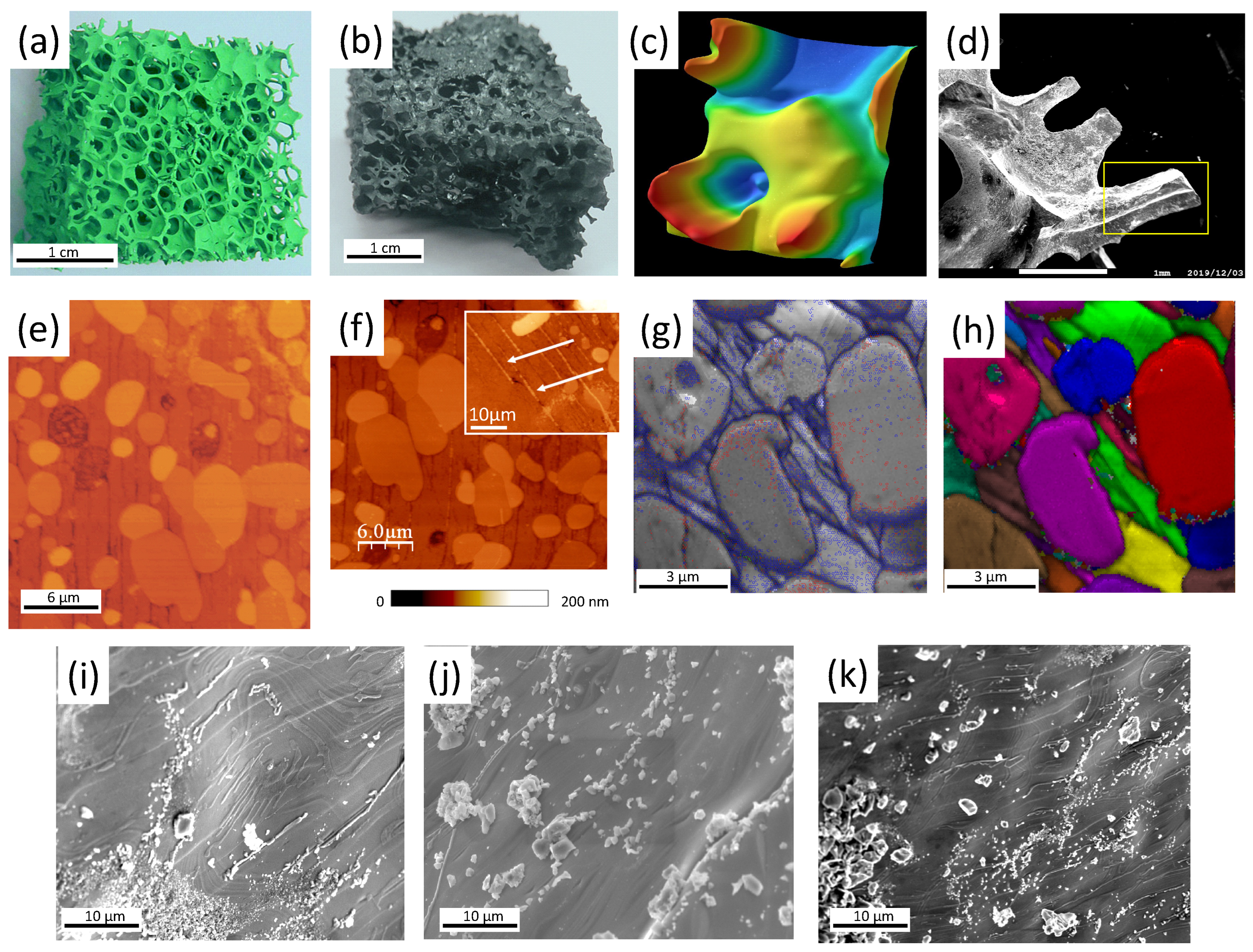
Figure 1. (a) Green Y-211 foam obtained after first sintering. (b) Fully-reacted superconducting YBCO foam after the IG-processing. The remnants of the seed crystal are still visible on top of the foam sample. (c) Digitally processed 3D-images of the foam windows, struts and ligaments (obtained with a digital microscope with variable focal depth, see main text). (d) Broken out section of the foam revealing the 3D-arrangement of the foam struts. A strut section like the one marked by the yellow square was employed for the further analysis and the resistance measurements. (e) AFM topography image of a foam strut revealing several large Y-211 particles (bright) and the elongated YBCO grains separated by groove-like structures. (f) AFM topography image indicating that many nanometer-sized Y-211 particles are located within the GBs (grooves) in between the YBCO grains. The inset presents details of the minuscule Y-211 particles (bright, marked by white arrows). The color bar below the figure indicates the recorded height. (g) EBSD image quality (IQ) mapping. The EBSD-detected GBs are marked in red (1–5°) and blue (15–180°C). The recorded IQ-values were ranging between 60 (black) and 750 (white). (h) EBSD unique grain color (UGC) mapping the same sample section as in (g), where neighboring grains are colored in distinctly different colors to highlight the grain arrangement. (i) SEM image of the surface of a foam strut revealing an unique pattern of particles on the surface and some flow-like structures due to the liquid flow during the infiltration-growth processing. (j) SEM image presenting various particles located on the strut surface. EDX analysis [13] showed that these particles are mainly Ba 3 Cu 5 O y . (k) SEM image presenting the Ba 3 Cu 5 Oy-particles on the strut surface, which appear as tiny particles as well as as large clusters.
Preprints 94898 g001
Figure 2. Resistivity ρ ( T ) as function of temperature for an YBCO foam strut without an applied magnetic field ( μ 0 H a = 0, ■). The red line shows the determination of ρ n ( T ) by an extrapolation to the low-temperature region. The inset depicts the method used for determining the temperature T * by plotting ( ρ ρ 0 ) / α T .
Preprints 94898 g002
Figure 3. Resistivity of the YBCO foam as function of temperature measured in the superconducting transition region in various applied magnetic fields ranging between 0–7 T. A red filled circle marks the kink in the curves for applied magnetic fields of 3, 5 and 7 T.
Preprints 94898 g003
Figure 4. Derivatives plots of resistivity d ρ / d T versus temperature of the YBCO foam sample under different applied magnetic fields. Note the double-peak behavior at applied magnetic fields above 3 T.
Preprints 94898 g004
Figure 5. The upper critical field, B c 2 ( T ) (obtained using a criterion 0 . 9 ρ n , ) and irreversibility field, B * (criterion 0.1 ρ n , ) as a function of temperature for the studied YBCO foam strut. Straight lines with arrows on the extremities represent the difference between the start T c onset ( H a ) and the T c ( H a ) , which was designated as Δ T c ( H a ) .
Preprints 94898 g005
Figure 6. Plots of ln Δ σ vs. ln ϵ for the YBCO foam strut sample at (a) μ 0 H a = 0 T, (b) μ 0 H a = 1 T, (c) μ 0 H a = 3 T, (d) μ 0 H a = 5 T, and (e) μ 0 H a = 7 T in comparison with the Aslamazov–Larkin model. The five fluctuation regimes recognized are indicated by Preprints 94898 i001 for the critical regime (CR), by Preprints 94898 i002 for 3D fluctuations, Preprints 94898 i003 for 2D fluctuations, Preprints 94898 i004 for 1D fluctuations and Preprints 94898 i005 for the SWF regime.
Preprints 94898 g006
Figure 7. The widths of the 3D-, 2D-, and 1D-fluctuation regimes plotted versus the applied magnetic field, μ 0 H a . The lines drawn serve as guide for the eyes. The width of the 3D- and 1D-regimes decrease on increasing the applied magnetic field, whereas the width of the 2D-regime is found to increase.
Preprints 94898 g007
Figure 8. Variation of the zero-temperature coherence length along the c-axis, ξ c ( 0 ) , and the effective layer thickness of the 2D system, d, as function of the applied magnetic field. The lines drawn serve as guide for the eyes.
Preprints 94898 g008
Figure 9. Variation of the current density at 0 K, J c ( 0 ) , as function of the applied magnetic field, μ 0 H a . The red line drawn serves as guide for the eyes.
Preprints 94898 g009
Table 1. Critical transition temperatures extracted from electrical measurements and excess conductivity results analyzed at different applied magnetic fields for YBCO foam sample.
H a (T) T c offset (K) T c onset (K) ρ n (m Ω cm) T c 1 mid (K) T c 2 mid (K) T g (K) T LD (K) T ( 2 D 1 D ) (K) T ( 1 D SWF ) (K)
0 90.16 101.5 0.429 96.26 96.9 103.10 108.79 119.67
1 88.01 99.47 0.405 92.86 95.02 100.65 107.51 117.38
3 84.14 96.03 0.3789 91.85 90.60 93.66 98.09 106.95 117.27
5 82.42 94.85 0.3770 91.82 89.29 93.27 97.29 107.48 116.31
7 80.79 94.08 0.3748 90.64 87.66 92.21 96.54 106.82 115.35
Table 2. The Gaussian and critical exponents deduced from excess conductivity results performed at different applied magnetic fields for YBCO foam sample.
H a (T) λ CR λ 3 D λ 2 D λ 1 D λ SWF
0 0.32 0.51 0.95 1.50 2.95
1 0.34 0.48 0.96 1.55 3.05
3 0.30 0.49 0.94 1.54 2.97
5 0.21 0.48 0.95 1.45 3.02
7 0.23 0.48 0.95 1.50 3.01
Table 3. Some values of J c ( 0 ) deduced from excess conductivity results reported in the literature to compare with the present YBCO foam strut data.
Material J c ( 0 ) (A/ cm 2 )   reference
YBCO foam 125430 present work
Oxygenated and argon annealed YBCO 1390  [54]
YBCO polycrystal (solid state reaction) 89340  [39]
Ball milled YBCO 130380  [15]
Polycrystalline YBCO/ Zn 0 . 95 Mn 0 . 05 O 170000  [55]
Polycrystalline YBCO/ Al 2 O 3 318560  [55]
YBCO thick film 350000  [56]
Disclaimer/Publisher’s Note: The statements, opinions and data contained in all publications are solely those of the individual author(s) and contributor(s) and not of MDPI and/or the editor(s). MDPI and/or the editor(s) disclaim responsibility for any injury to people or property resulting from any ideas, methods, instructions or products referred to in the content.
Copyright: This open access article is published under a Creative Commons CC BY 4.0 license, which permit the free download, distribution, and reuse, provided that the author and preprint are cited in any reuse.
Prerpints.org logo

Preprints.org is a free preprint server supported by MDPI in Basel, Switzerland.

Subscribe

© 2024 MDPI (Basel, Switzerland) unless otherwise stated