1. Introduction
The first split-winding bearing motor was proposed by Salazar & Stephan [
1]. Victor in [
2] analyzed the feasibility of using a conventional induction machine as a split-winding bearingless motor. He performed position and current control of the machine; however, he observed that radial position control was not satisfactory for speeds below the rated limit. In recent years, [
3] studied the replacement of PID controllers for radial position control with controllers based on fuzzy logic. Noting the strong nonlinear and parameter-varying characteristics of induction motor bearings, he analyzed the contribution of Fuzzy controllers on transient and permanent regime performance. In order to reduce the number of equipment needed for machine control, [
4] optimized the structure of the motor bearing by proposing a new way to connect the coils in the machine stator. In [
5], the machine’s performance operation with a conventional state estimator and a neural state estimator was compared.
Speed control operating with the bearing motor was studied by [
6,
7]. The Artificial Neural Networks (ANN) technique was chosen. The ANFIS technique was investigated and studied by [
8,
9,
10]. The adaptive neuro-fuzzy in motor studied by [
11,
12]. The speed control operating with the bearing motor was evaluated by comparing the implementation of classic PI control with an artificial intelligence technique. Thus, the Artificial Neural Networks (ANN) technique was chosen to replace the classic PI control technique. The first step in implementing ANN was choosing the data set, the ANN input data are the mechanical speed and the mechanical speed error. The ANN output data is the torque current.
This work aimed to study and implement the artificial intelligence technique applied to vector speed control for the split wound type bearing motor based on the induction motor. The aim was to investigate and simulate the intelligent ANFIS techniques and Neural Networks to evaluate the performance of the motor-bearing in the following conditions: operating as an estimator and as a speed controller. The split winding motor-bearing, which was adopted in this work, was proposed by [
13]. In the experimental part, the TMS3208F28335 DSP was used to integrate the control algorithm with the current, position, and speed interfaces, by composing a cascade system. The intelligent technique implemented was the Neural Network, which acted as a speed controller. The position and mechanical speed results were compared with the PI speed controller and the Neural Controller. The control algorithm implemented in the TMS320F28335 DSP was developed in ANSI C programming language. The motor-bearing system is located in the Computer and Automation Engineering Laboratory (LECA) at UFRN.
The article describes the implementation details of controllers that provide the opera- 49 tion of the bearing motor. The system is current, radial rotor position, and speed, which 50 operate in a cascade. Control loop implementations started with the loop from the in- 51 nermost (fastest) control to the outermost (slowest) loop, following the sequence: current 52 control, position control, and speed control. Speed and position controllers are responsible 53 for the generation of reference currents for current control.
3. Design and Analysis of the ANFIS System
The structures adopted in the Neuro-Fuzzy estimator were based on two estimators, one for estimating the magnetizing current and the other for estimating the rotor flux. The ANFIS 1 estimator uses the following inputs: the direct field current and the delayed magnetizing current, and as output, the magnetization current. The ANFIS 2 uses the following inputs: mechanical velocity quadrature current angular velocity as output estimated after discretization .
In order to find the best configuration, it was performed several training with different parameters to obtain better criteria for the simulations according to
Table 4 and
Table 5.
The criteria adopted in both estimators were 300 times for training and zero-tolerance error.
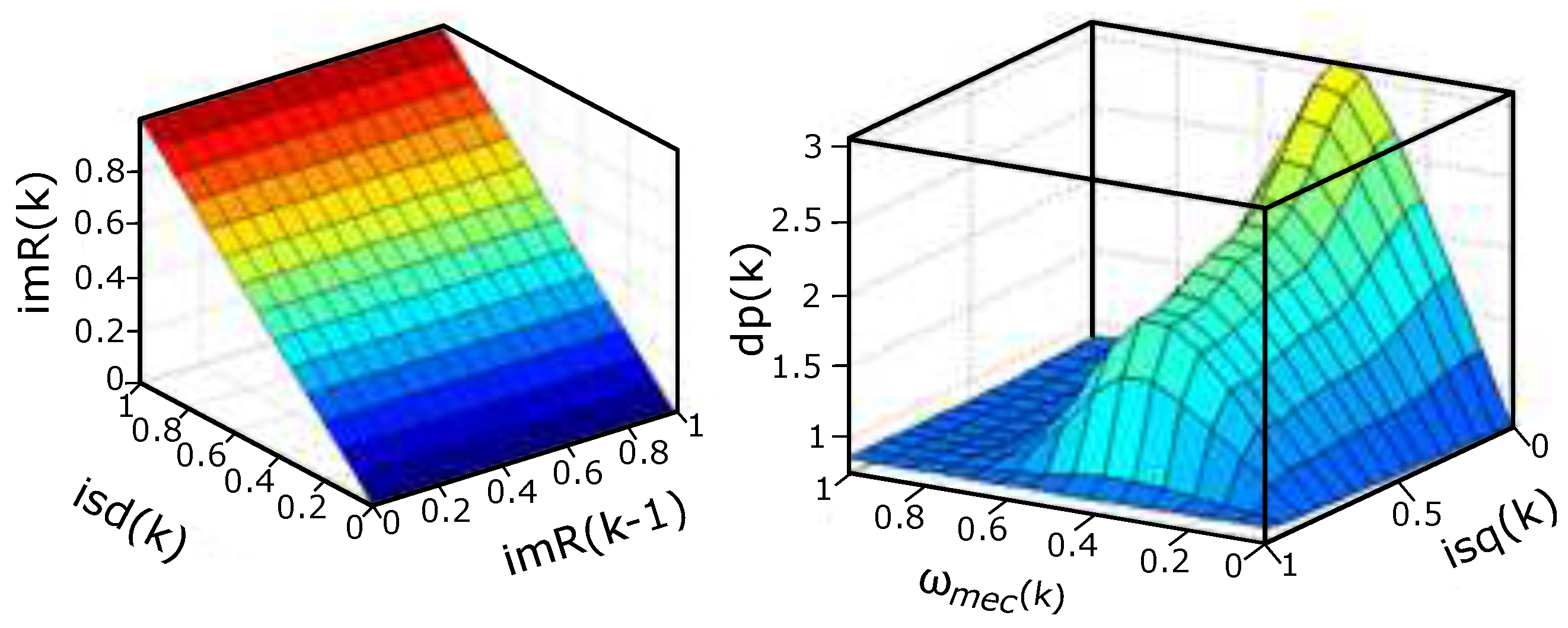
Figure 4 (A) illustrates the Fuzzy surface obtained as a result of quadrature and magnetization current training. It is deduced that the linear result obtained is due to the centered rotor.
Figure 4 (B) illustrates the Fuzzy non-linear surface obtained due to speed training mechanics and quadrature current.
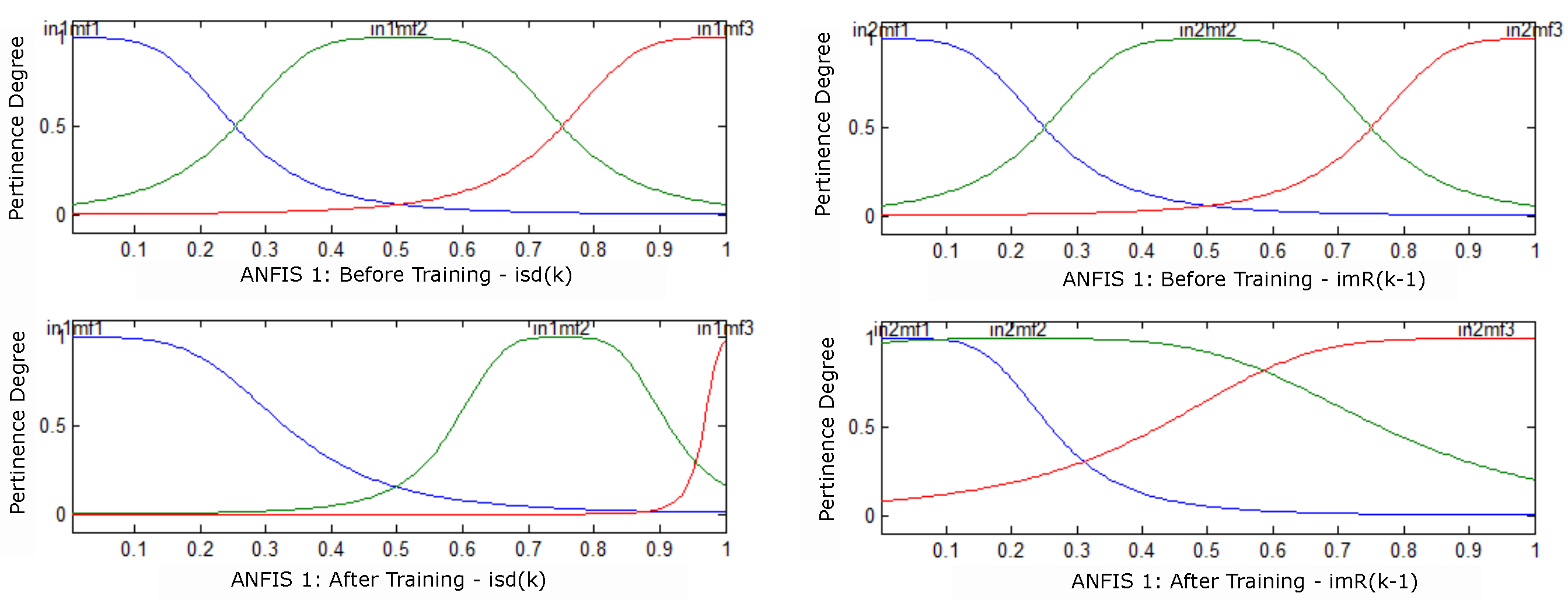
Figure 5 illustrate the behavior before and after training to adjust the memberships:
and
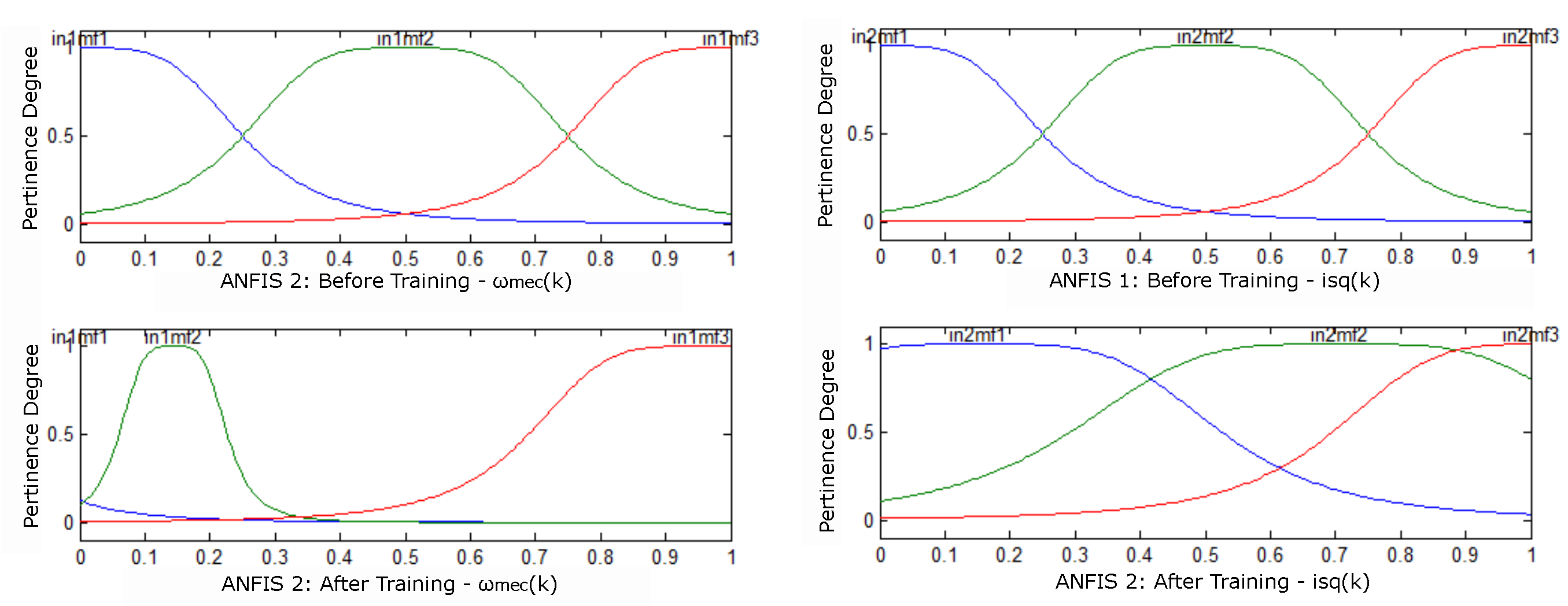
the curves [blue, green and red] represent the rules generated by ANFIS and {in1mf1, in1mf2 and in1mf3} are the memberships generated by ANFIS 1 and by ANFIS 2 are {in2mf1, in2mf2 and in2mf3}.
It is observed that after the end of the training, the pertinence functions of
Figure 6 were adjusted for each input of estimator 1 of
Figure 4 (A). With the result of the training of the ANFIS 2 estimator, the membership settings for the entries were obtained.
Figure 6 illustrates the behavior before and after mechanical speed training.
Figure 6 (A) shows the cancellation of membership already in
Figure 6 (B) there was no cancellation of membership, but a distribution of the same. These elimination and distribution results are pertinent to the Neuro-Fuzzy training.
3.1. Results of Simulations with the ANFIS Estimator
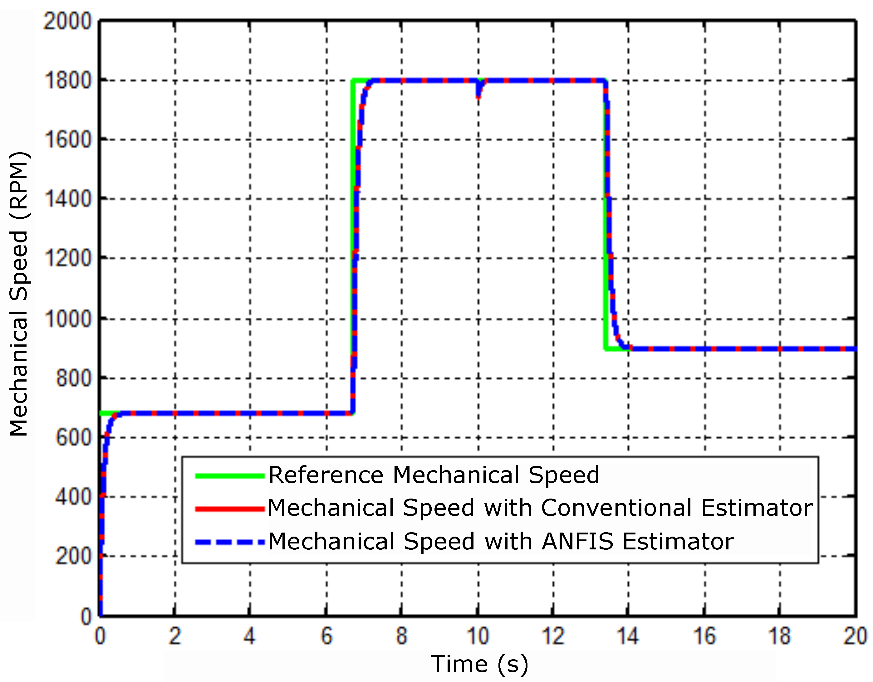
The simulations were run in the range of 0 to 20 seconds. The result shown in
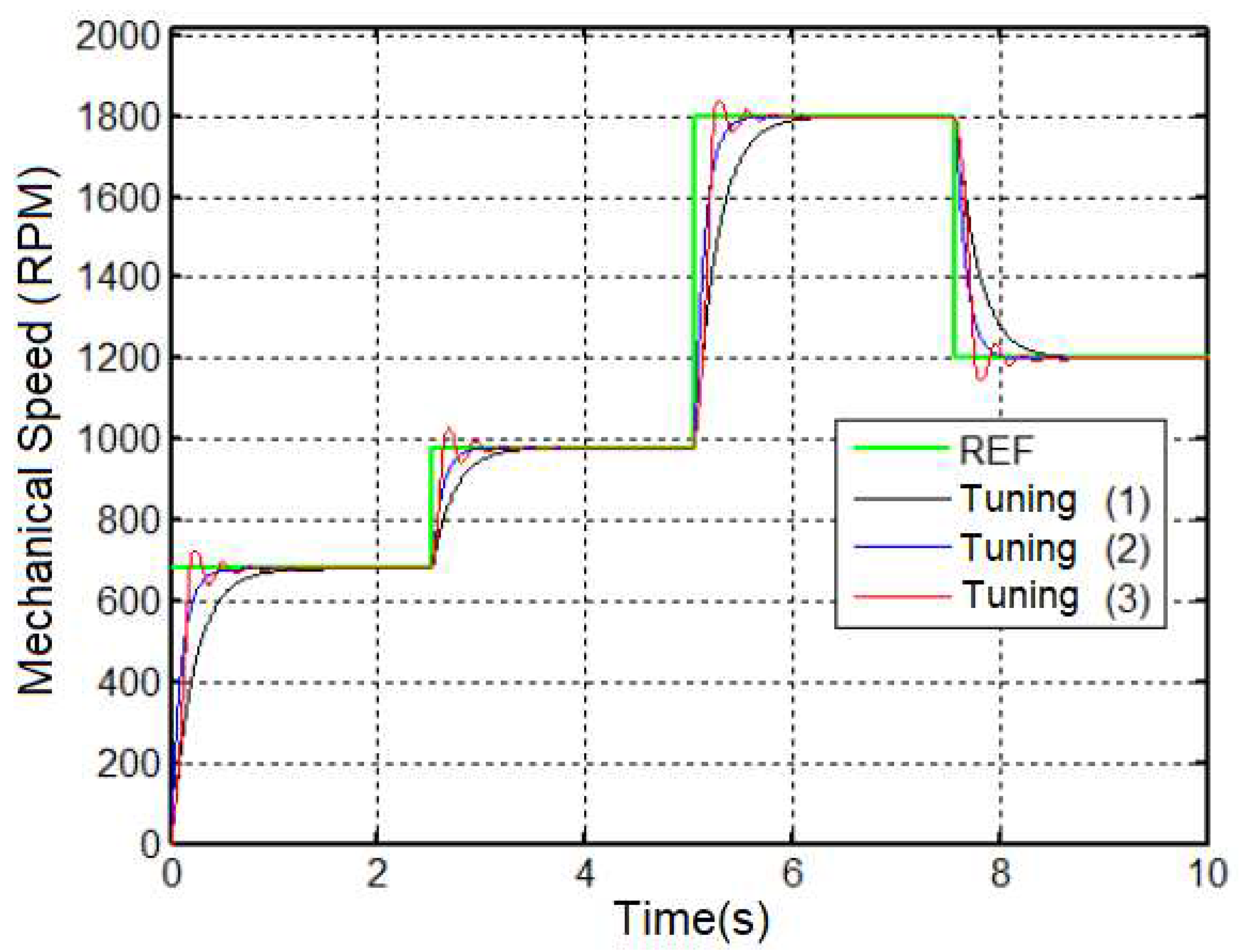
Figure 7 shows the mechanical speed of the motor simulated subject to the following reference changes 680, 1800, and 900 rpm, and then a perturbation at the instant 10 seconds is applied. The disturbance was an application of a load torque with a nominal value to
N.m.
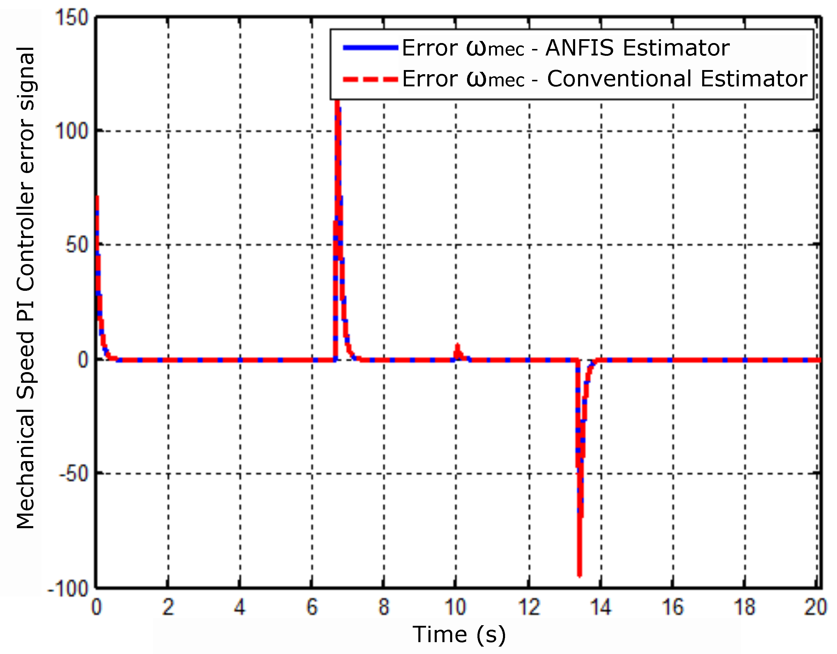
The following result shows the performance of the controller error speed referring to the conventional estimator model and the estimator ANFIS,
Figure 8.
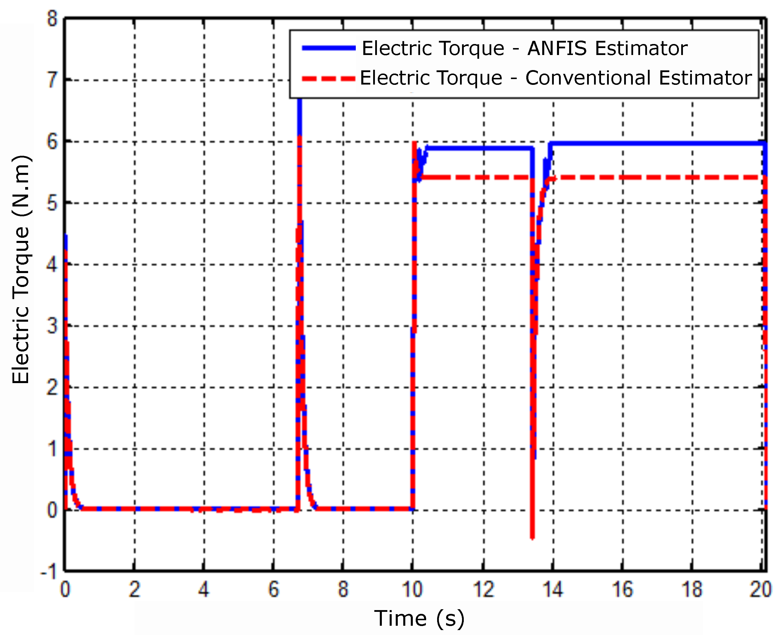
Figure 9 shows the behavior of the electrical torque in the conditions imposed in the simulation with conventional estimators and with the Neuro-Fuzzy estimator.
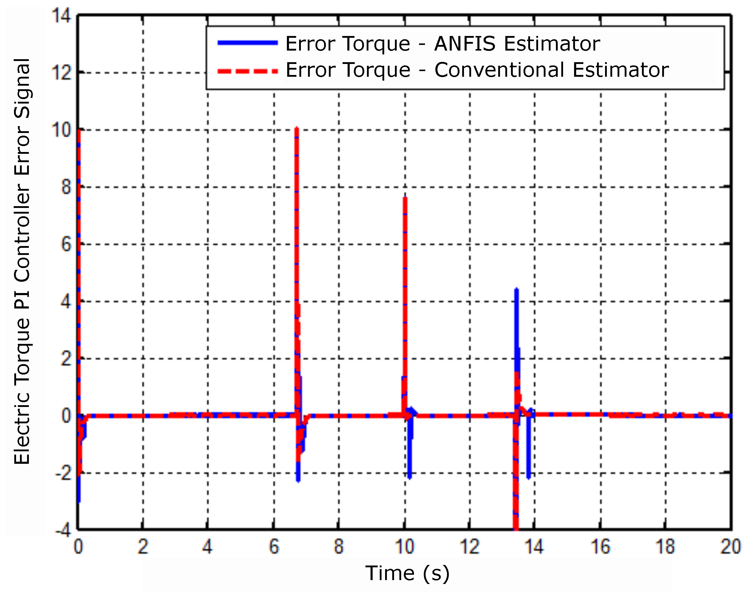
Figure 10 illustrates the PI controller error signal for electrical torque and identifies the controller error behavior for each simulated estimator.
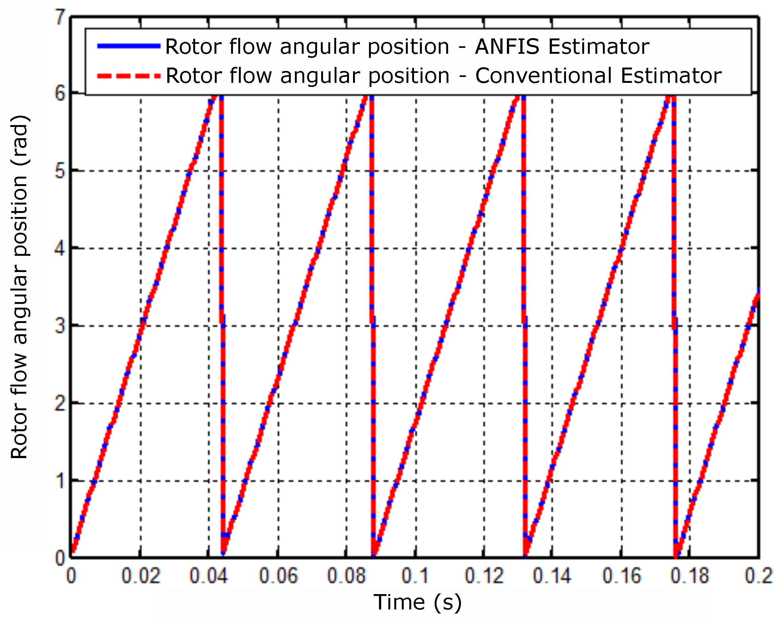
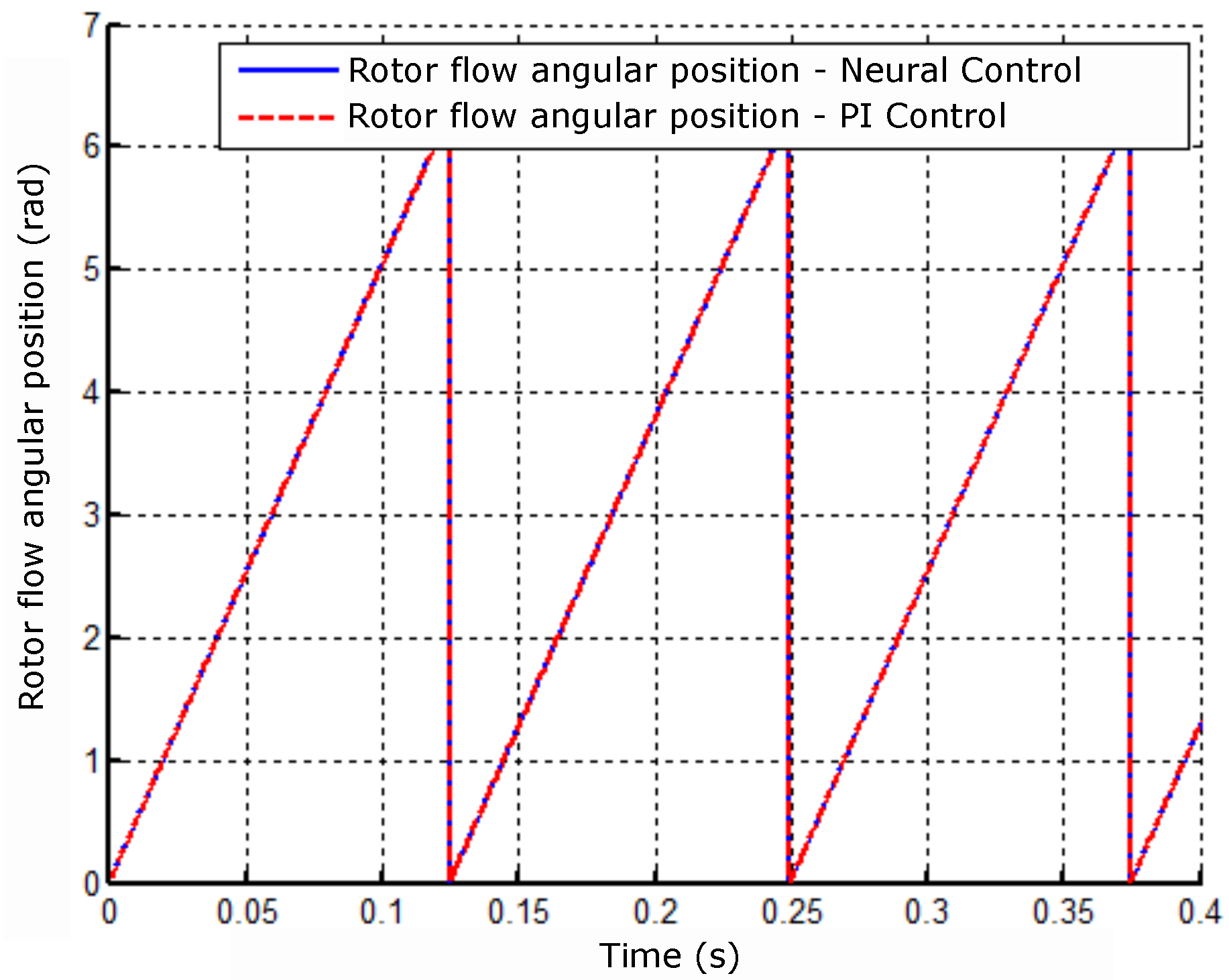
Figure 11 shows the behavior of the angular position with a zoom in an operating range of 0 to
s. It is observed in this result from the
timing for the estimators.
5. Experimental Arrangement
According to [
17], the
kVA three-phase induction motor received modifications to operate a bearing motor, for example: the configuration of the double star coils and the removal of one of the bearings from one end of the rotor shaft. This last modification caused problems in the work of [
2], according to which the problem of eccentricities of the motor-bearing shaft caused when there is displacement of the rotor made it difficult to adjust the position controller gains. The orbits were designed by rotating the shaft manually and then translating it through the periphery of the air gap. According to [
2], after installing the self-aligning bearing, the shaft started to produce several orbits when peripherally displaced.
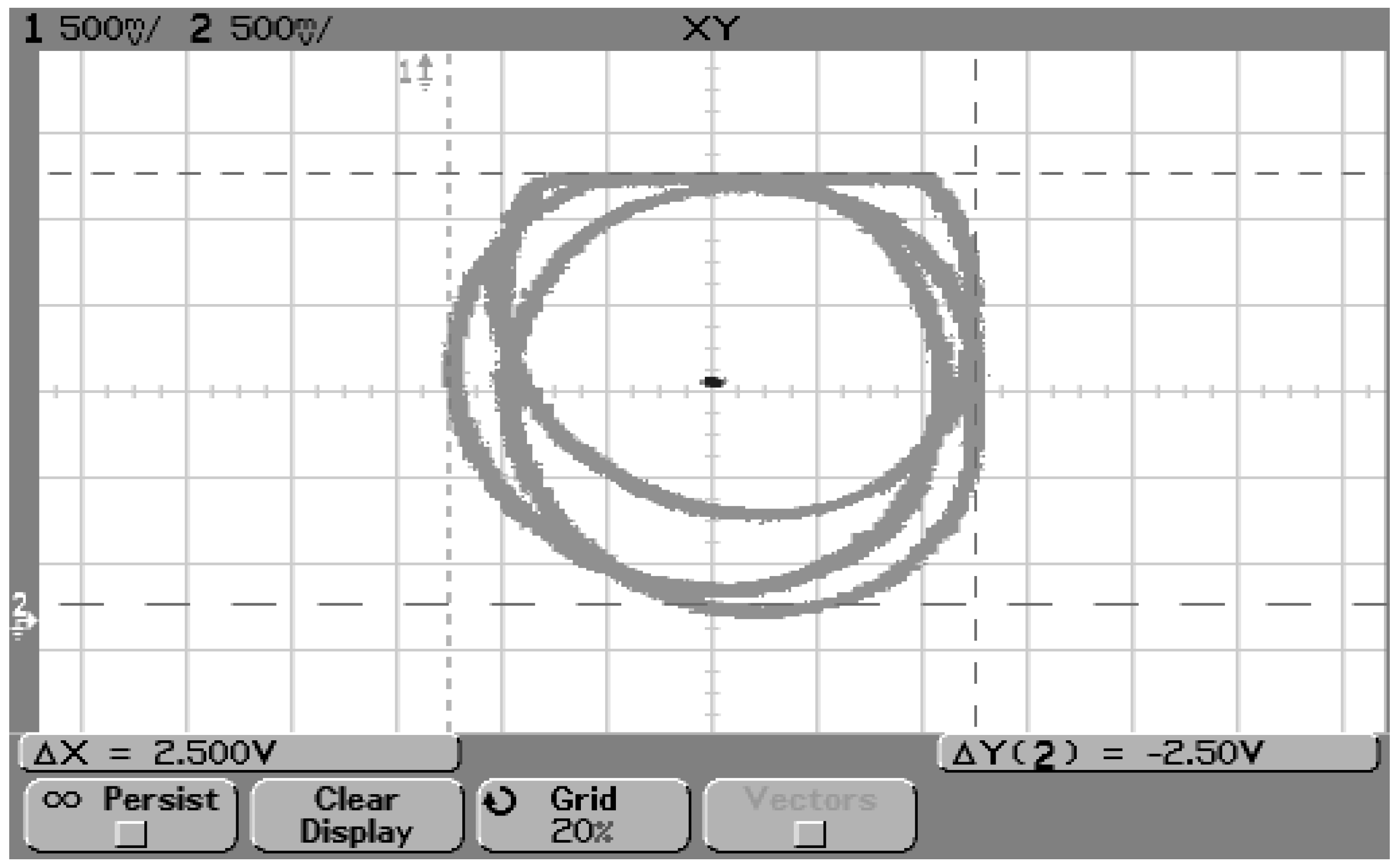
Figure 18 shows three possible orbits designed by moving the shaft peripherally in the housing box of the top bearing.
After replacing DSP 2812 with DSP 28335, the empirical tuning of Position PD controller has become a difficult task. In order to solve the problem of the eccentricity of the rotor shaft, the induction motor was taken to the Laboratory of Mechanics and Turning, which is located on the Parnamirim campus of the Federal Institute of Education, Science and Technology of Rio Grande do Norte (IFRN). In order to correct the imbalance, the induction motor was disassembled, and the rotor shaft composed of the bearings and the disc was positioned in the lathe to perform roughing on the disc. In order to increase accuracy, it was used the clock in thinning.
However, the eccentricity problem persisted, decreasing only the number of orbits. With the correction of the unbalance of the shaft in the lathe, the number of orbits went from three to two. This phenomenon made it difficult to tune in to the position controller. The solution found was the replacement of the conventional induction motor modified from the work of [
2] by the prototype of the bearing motor used in the work of [
13], which was located in the Laboratory of Computer Engineering and Automation (LECA) at UFRN.
According to [
13], the bearing motor is a conventional induction machine adapted to operate without its mechanical bearings, having its radial positioning controlled by magnetic fields. The data used as parameters for the control of the machine were from the
Table 7.
After the replacement of the motor, it was necessary to configure the connection of the electric motor. For this, the coils and they were respective phases, because, according to [
13], the stator coils suffered some changes, they were divided in half as a strategy to carry out of control. In
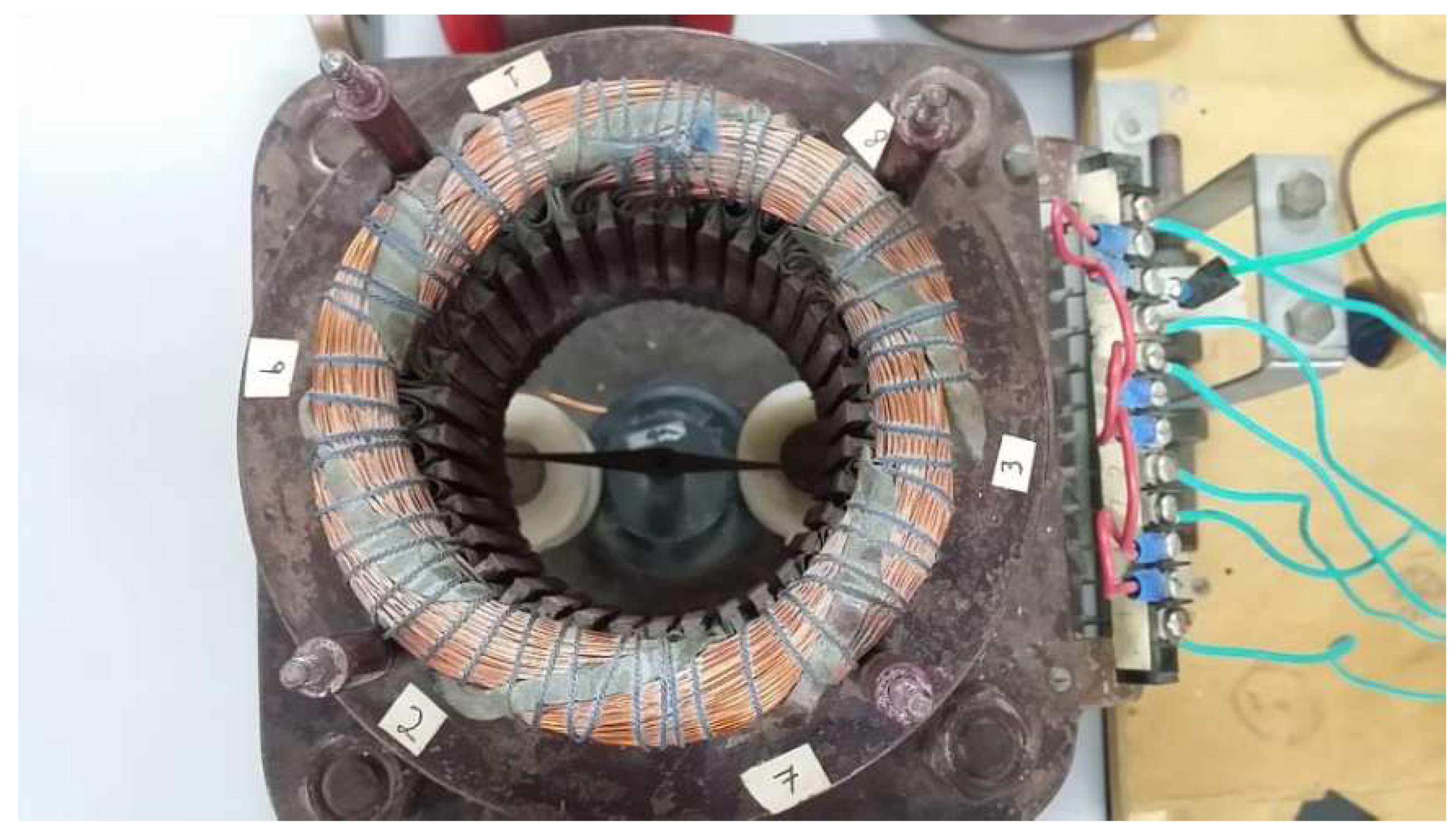
Figure 19, the location and identification of the groups of coils.
Based on the experiments,
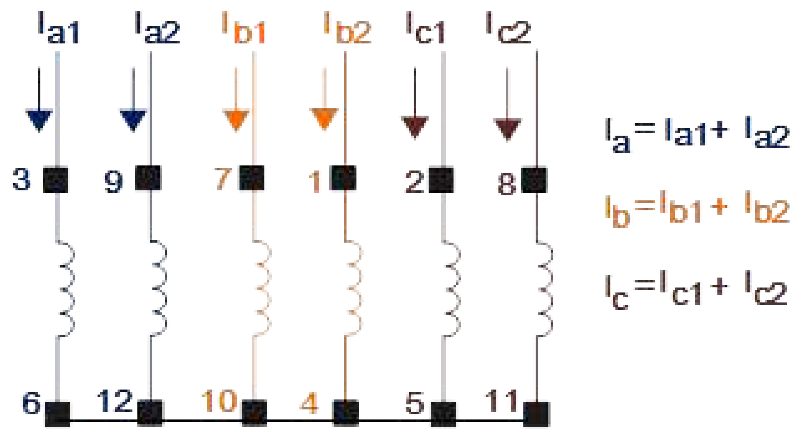
Figure 20 shows the arrangement of connections of these windings for operation as a bearing-less machine of the split coiled.
In order to facilitate the identification of phases and coil groups for name the
X and
Y axes for position control, it was necessary to perform two experiments with the aid of a compass. It is possible to check the compass orientation indicating the
Y direction, shown in the
Figure 21.
The result of
Figure 21 identified each coil group according to the sequence of
Figure 20. For this, each group of coils was excited with continuous tensions.
However, it was necessary to adjust the position and speed of the related peripheral to allow effective control under the conditions imposed on the bearing motor. These modifications are presented in the following sections.
5.1. Radial Position Sensors
According to [
18], the radial position control for a bearing motor consists of making the rotor float, that is, without mechanical contact with the stator. Further details on position sensors can be found in [
14].
Figure 22 shows the electronic circuit used with the AEC 5505-04 sensor.
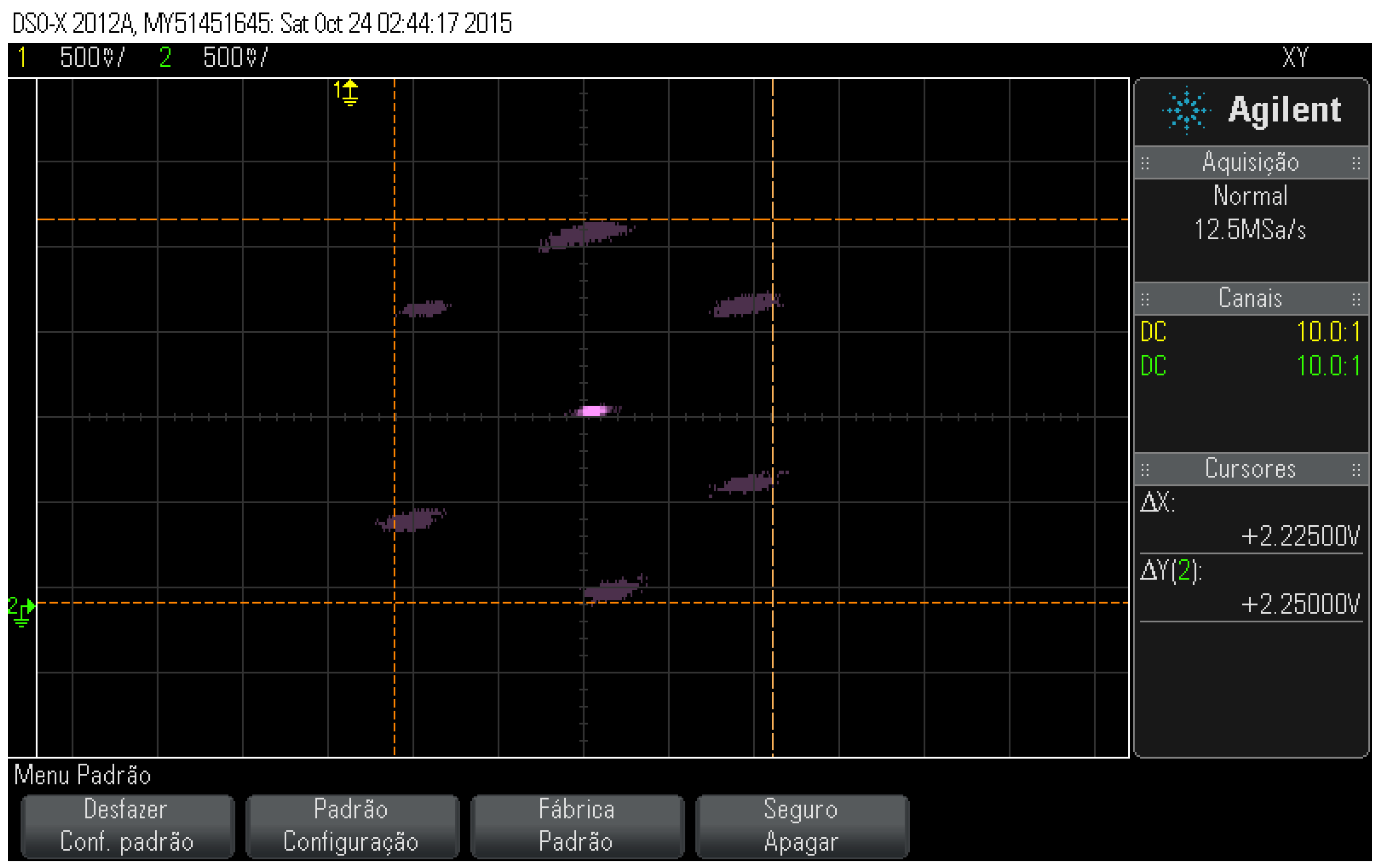
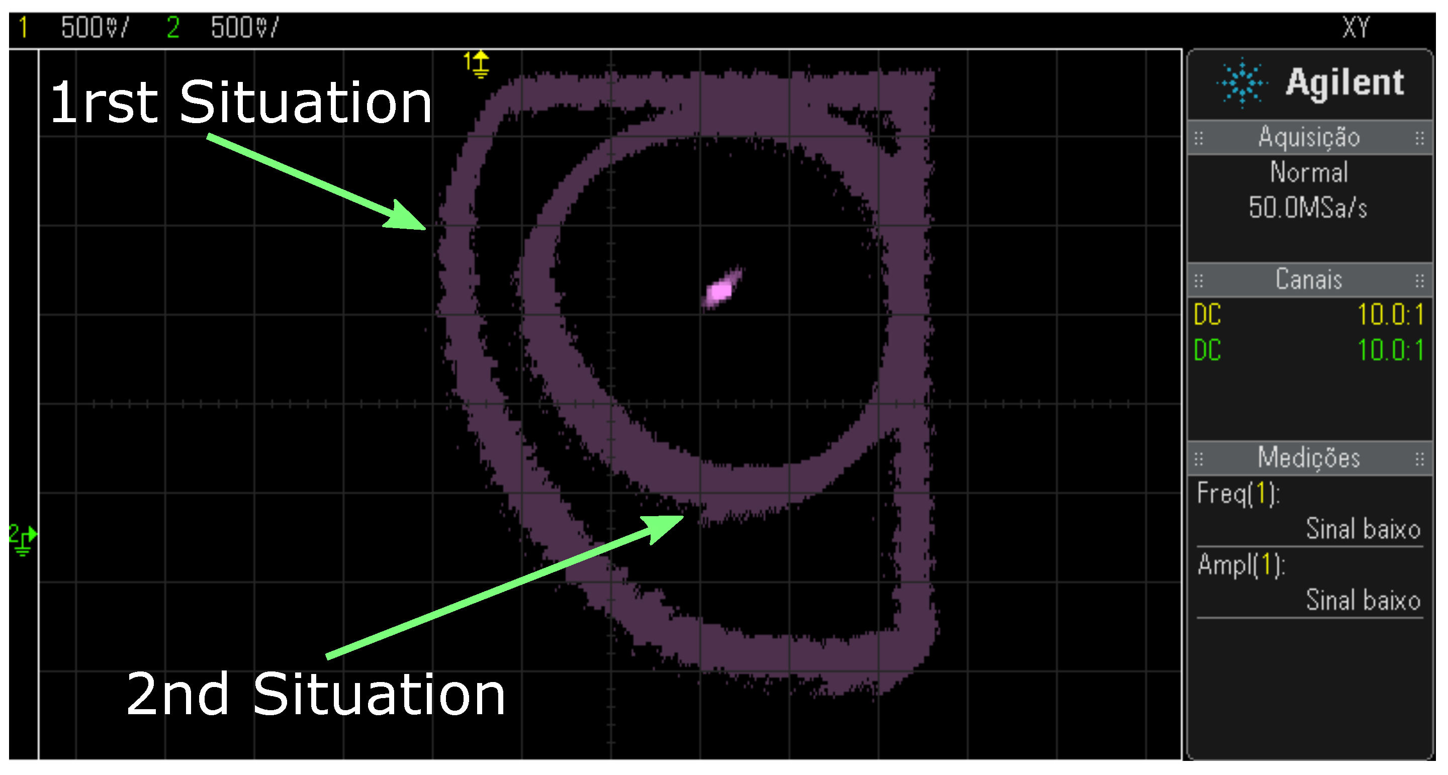
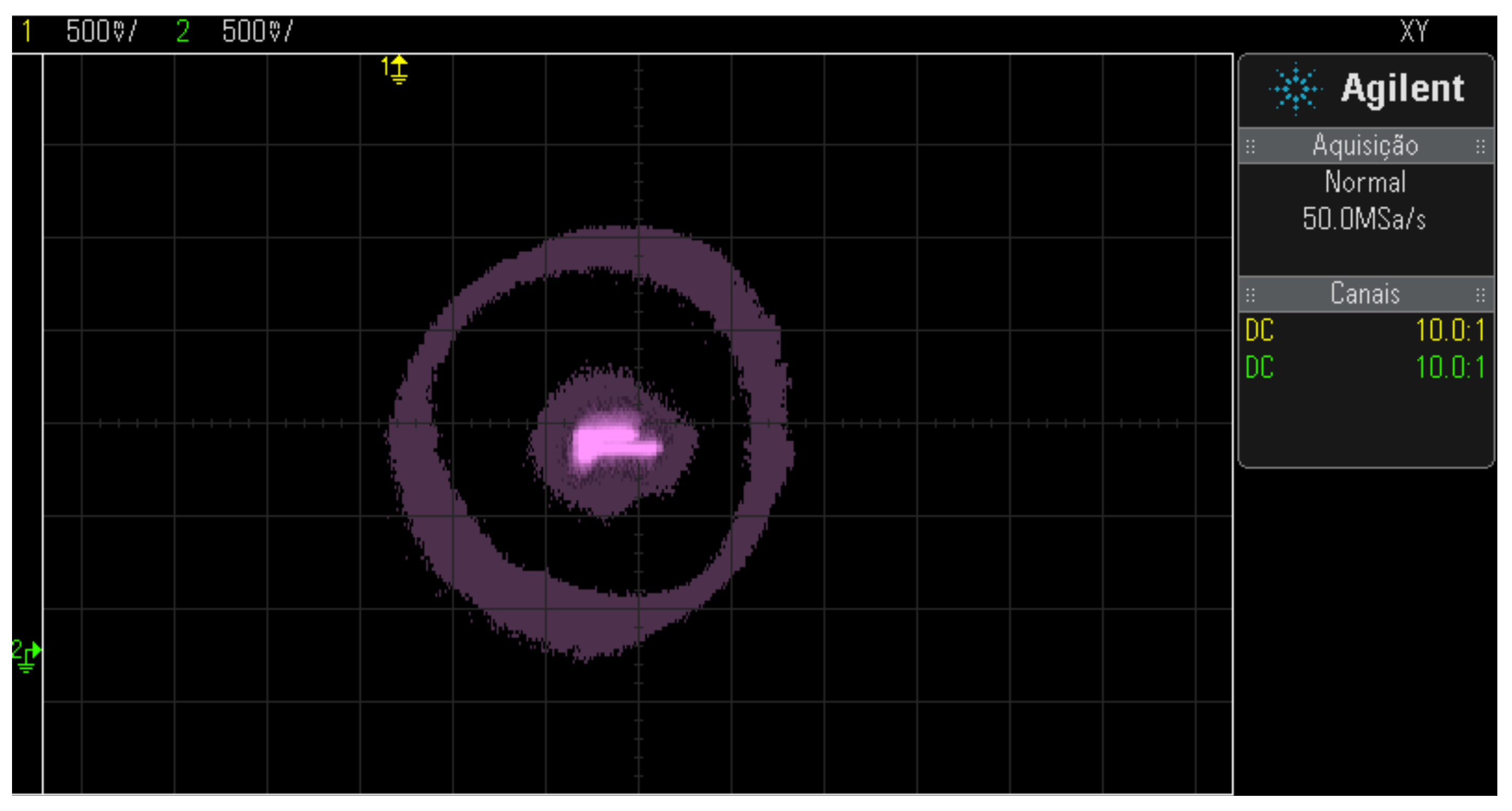
Figure 23 shows the radial displacement for two situations. The first situation presents a more extensive area referring to the maximum limit of the displacement between the axes, as well as signals reaped on the
X and
Y axes, while the second behavior presents the maximum limit of the desired radial offset for position control, both displacements were performed manually.
The solution in the second radial displacement was possible by attenuating the signals from the
X and
Y sensors with the addition of two
resistors before the operational amplifiers present in the diagram in
Figure 22. The resistors
were positioned at the input of the
X and
Y axis position signals. However, another problem persisted, the calibration of the sensors according to
Figure 24.
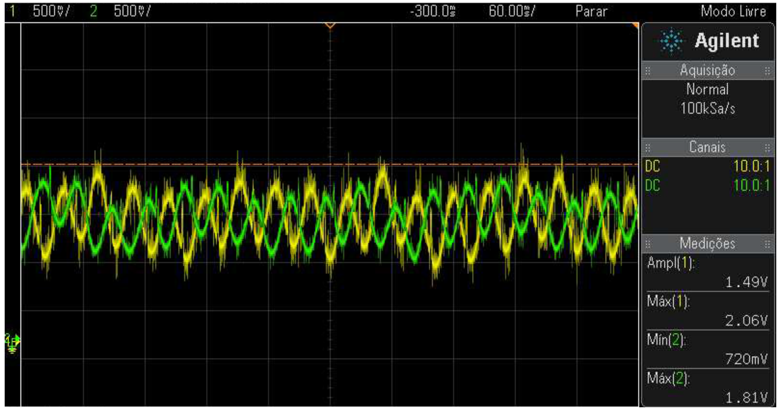
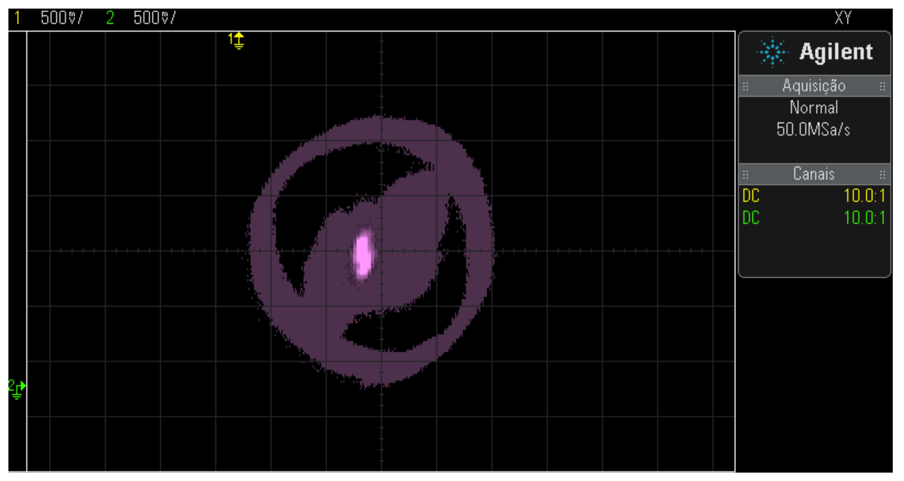
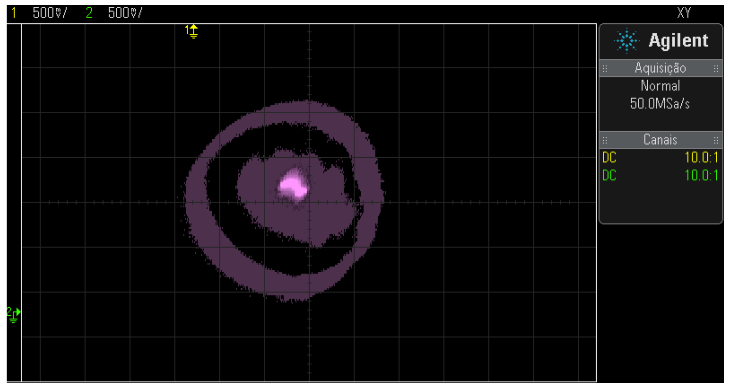
Figure 24 (A) shows a distorted figure, justified by the presence of the signal.
Figure 24 (B) where there is reaping in the
Y-axis signal represented by the color yellow. This problem can occur in the axes signals
X and
Y. In this case, the correction of this problem is done by adjusting the offsets. To do this, you must make the Y-axis signal behavior do not show any signs of mowing. When the Y-axis sign is approximated the sign of the
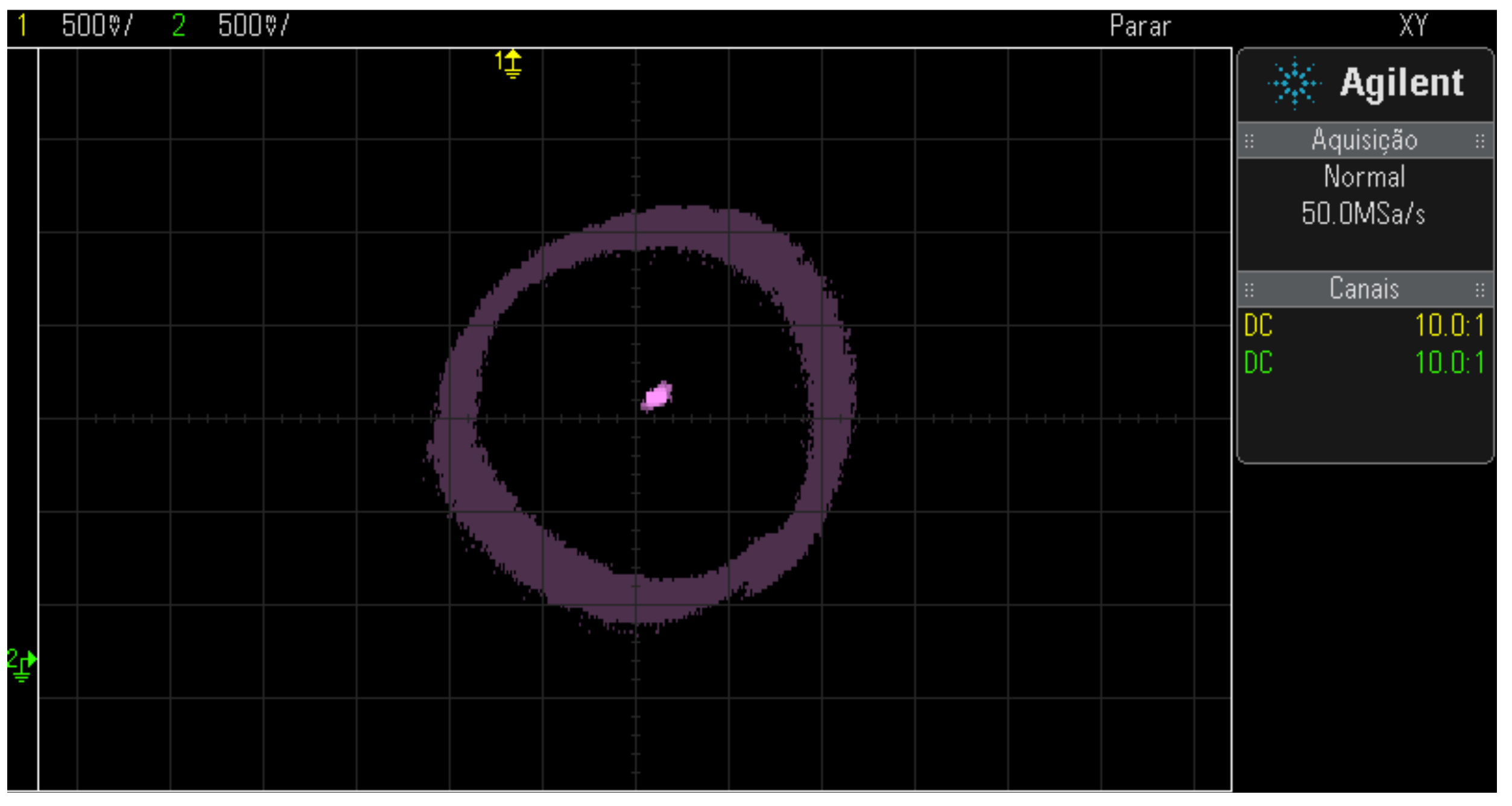
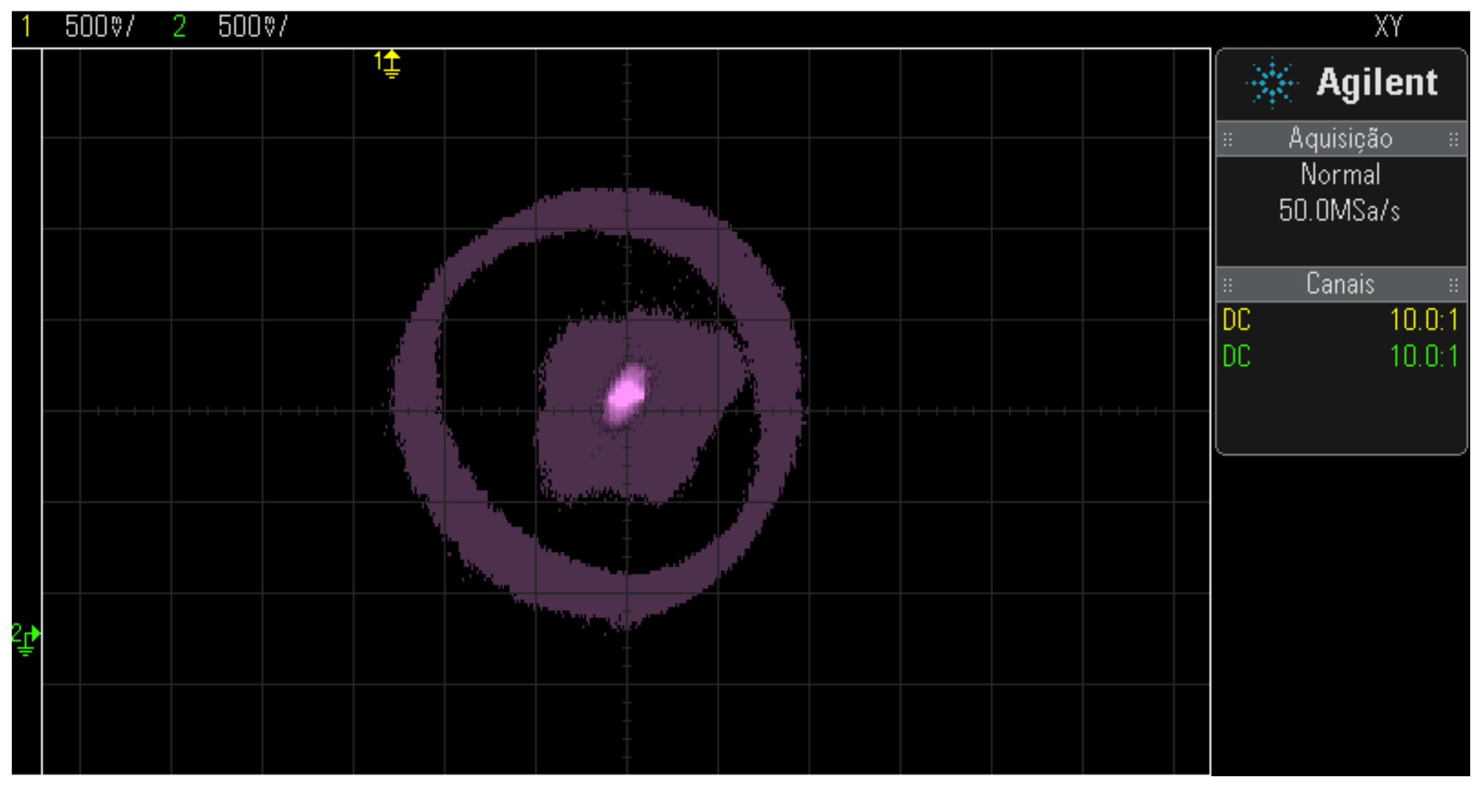
X-axis, the result of adjusting the offsets results in the
Figure 25. The behavior of the signals equivalent to the
X and
Y axes must be adjusted until you get the behavior of
Figure 25.
After replacing the bearing motor, the problem of rotor eccentricity, as can be seen in
Figure 26.
Another advantage identified in replacing the bearing motor was the increase in the air gap, which went from mm to mm, which allows a larger range for empirical tuning of position control.
5.2. Rotation Sensors
According to [
14], a rotating machine, when subjected to a torque on the shaft, in addition to needing more current in the coils, it also undergoes a variation in rotation. Thus, it is essential to know the rotation in real-time and the currents in the coils to implement a control machine rotation. In order to measure the rotation on the axis of the bearing motor, an encoder consisting of a disc was adopted uniformly perforated, a receiving transistor, and a light-transmitting LED structured infrared. However, in the tests, it was found that the circuit previously used by [
18] had noise problems and sometimes loss of pulses, causing loss of measured speed value or measurement error.
Among the peripherals that make up the bearing motor, such as those that were used in [
2] and presented in the work of [
18], there was a need to modify and to improve only the position interfaces and speed, the others did not change.
5.3. Complete System
In [
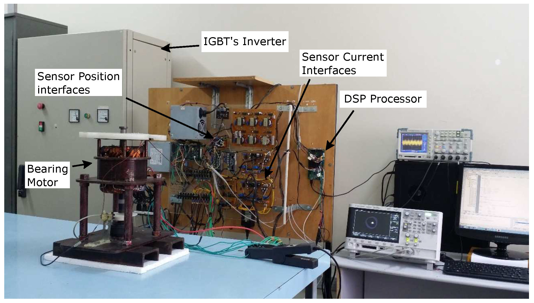
2], it is briefly explained that alternating current, from source to the power of the stator coils, is transformed into current continuous in the converter and again transformed into alternating in the inverter frequency. The modulation of current in frequency inverters is performed through signals from the DSP control system. The current produced generates both torque and radial forces from rotor positioning. The mechatronic system, including each of the elements composed by the system and other components such as interfaces, sensors, and command devices, can be seen in
Figure 27.
This section dealt with the details of the changes made to the interfaces with the bearing motor. Basically, there were changes in the position and velocity sensors, and after adjustments, the system was able to implement the control structure and obtain the experimental results, exposed in the following section.
8. Radial Forces Generation
Signals
,
come from the position control. Then, they undergo a rotational transformation to the static orthogonal system and transform into
,
and Lastly there is a coordinate transformation biphasic to triphasic, resulting in
,
, observed, that the controller signals
,
, after the transformations, they have added to the phase current references or subtracted in each half group of coils from phases
A,
B, and
C, respectively, to control the restoring forces of the rotor position, (Equation
6).
In these equations, , , and , are the imposed phase reference currents and , , , , , , are the reference currents for position control. Due to the nonlinearity of the system, the tuning of the controllers becomes difficult to obtain; however, the parameters of the controllers were determined empirically.
8.1. Vector Speed Control
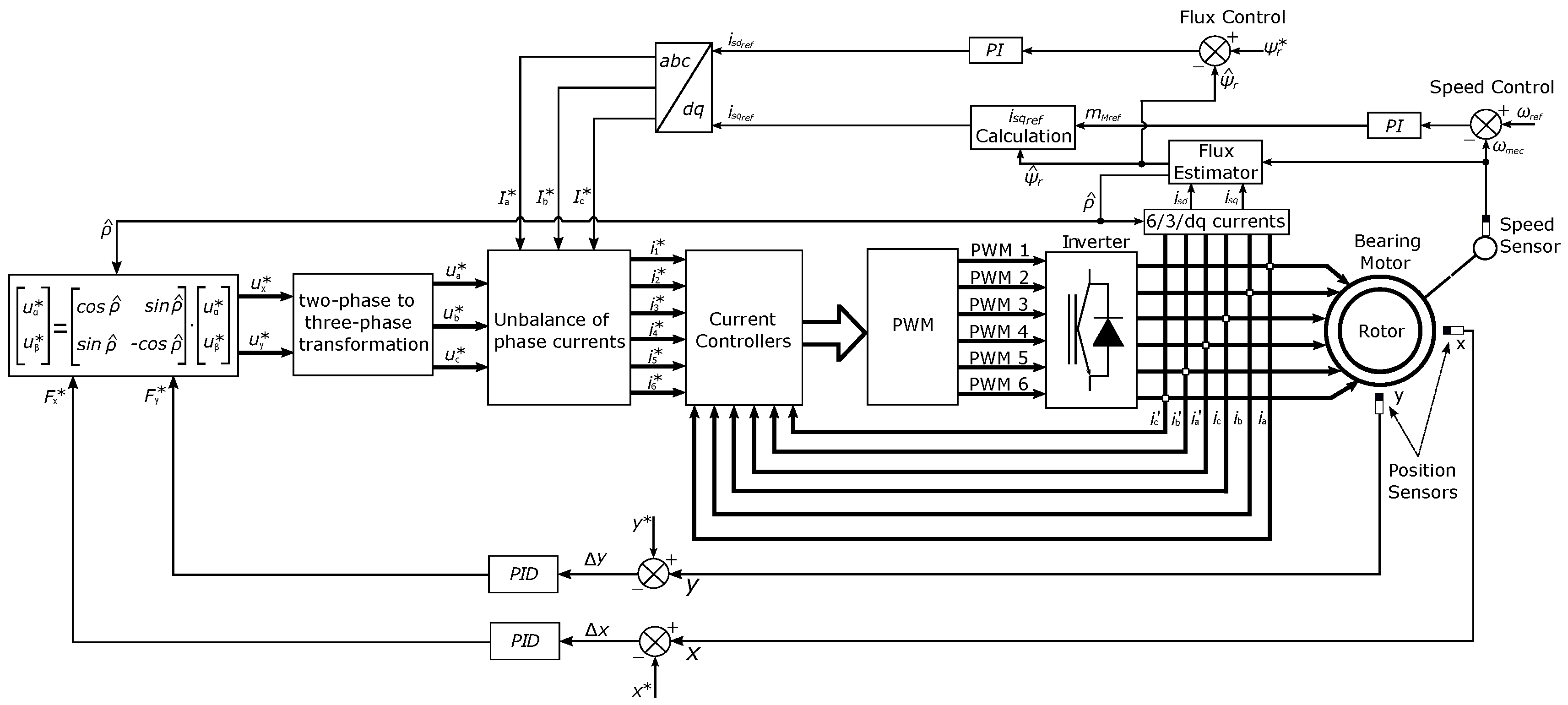
The speed controller used is a PI (Proportional-Integral) with anti-windup, the feature that interrupts the integration process when output has already reached a maximum saturation value [
21]. For the implementation of velocity vector control, initially, the structure of control of
Figure 28 using flow estimator. The big advantage of this structure using this estimator is the presence of a small number of equations, minimizing the computational effort [
22].
The flux estimator used in [
22] is given by:
In this,
,
the estimated flux;
the mutual inductance ;
the field current. Equation (
7) is calculated from the field current
and the inductance mutual
. Thus, the calculation of the torque current (
) obtained from the equation (
8) .
Here,
reference torque;
the inductance of the rotor;
, the flux reference rotor; and
P, the number of pole pairs. However, this structure does not was chosen for the following reasons: the difficulty of tuning in empirically the control loops, which consumed more time, and the fact of not having the necessary machine parameters to be used in equations (
7) and (
8).
However, it was thought to obtain the parameters from laboratory tests, which were discarded due to the following disadvantages: A delay in the digital implementation of the control structure may be a physical problem with the engine, generating more time for its solution or maintenance. Therefore, the control system implemented for the vector control of speed of
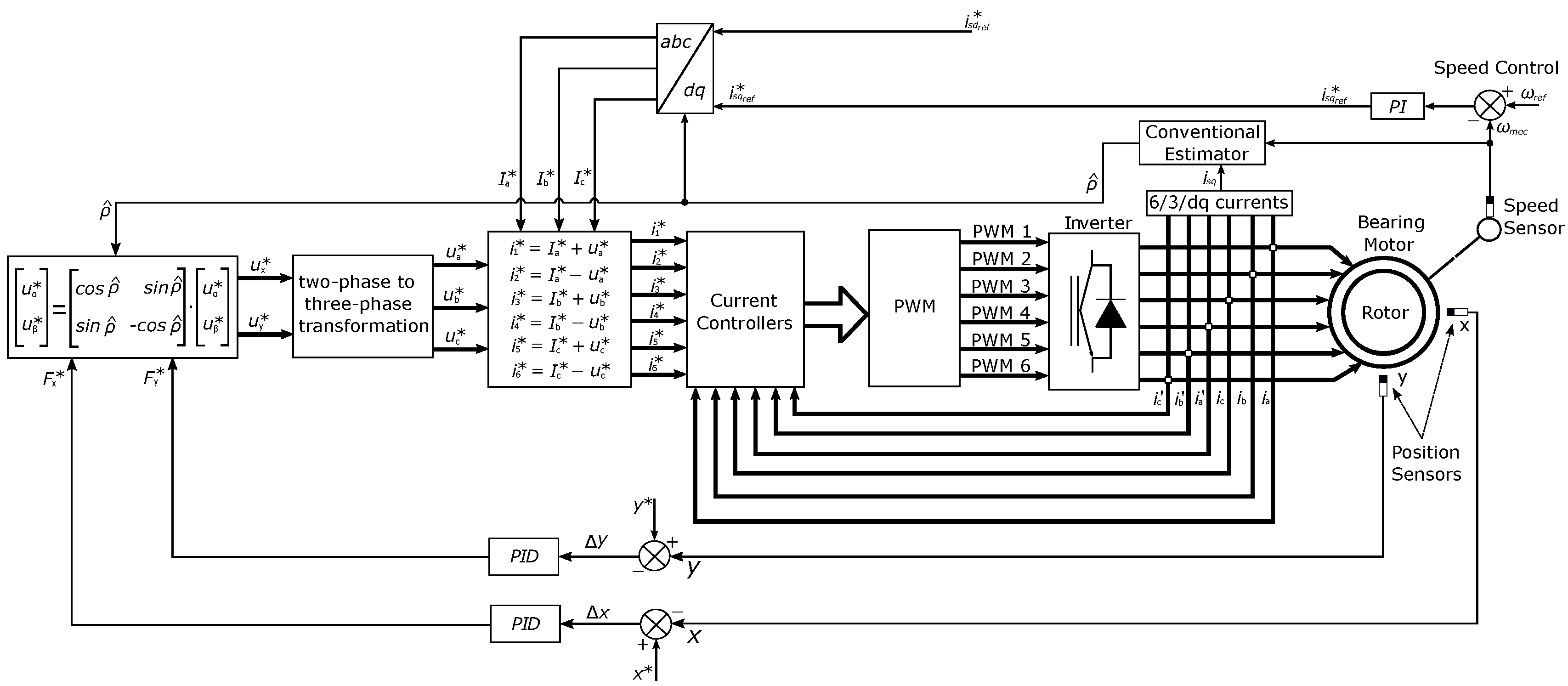
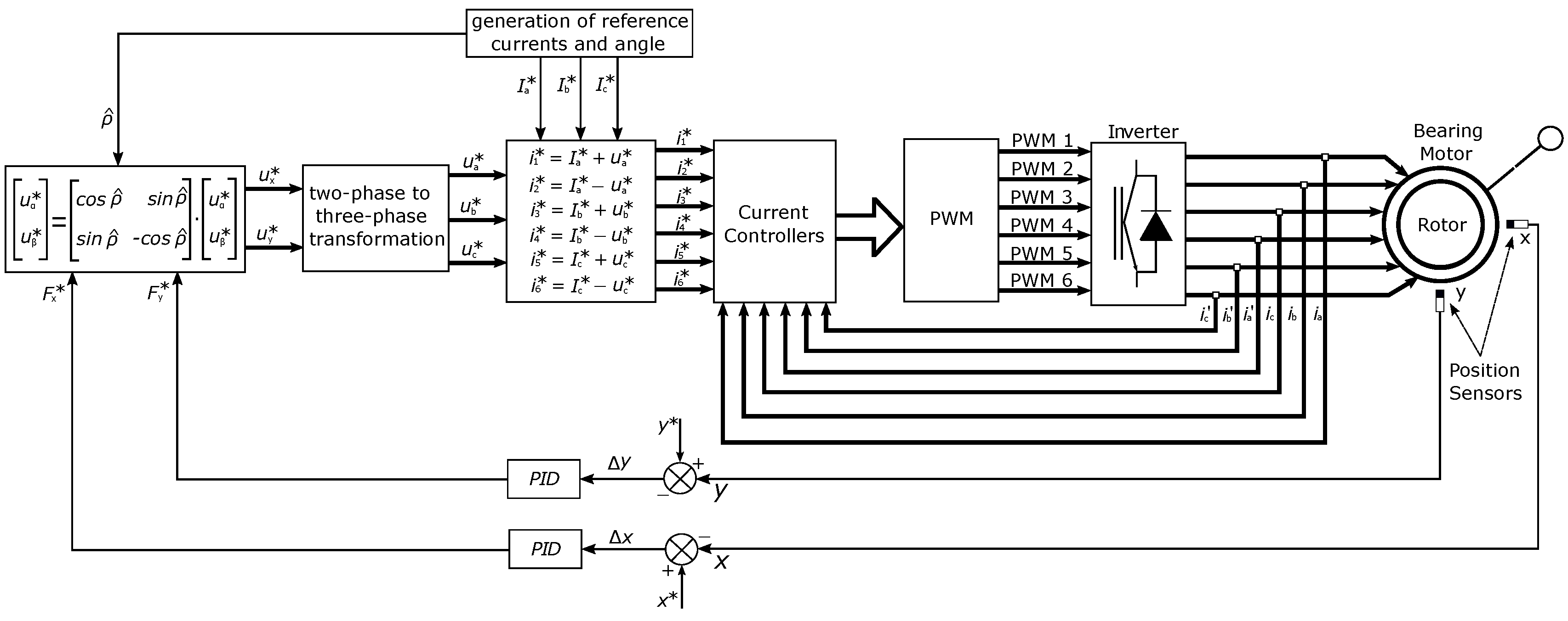
Figure 29 took into account two simplifications: impose a reference field current to not implement flow control and eliminate the current torque calculation, causing the control output go straight into Park, and Clarke’s inverse transforms as torque investigation will not be taken into account. The structure of
Figure 29 has three loops, the outermost being the Proportional-integral (PI) speed control, which controls the rotor shaft speed from the sensed feedback and whose output is the torque current
the Proportional-Derivative Integral (PID) controller for the positions referring to the
x and
y coordinates of the rotor, since, in practice, the added integral action should decrease the regime error. Position control is classified as a regulator, unlike the current control system, which is classified as a follower [
20]. Therefore, the last control loop is the current one, the innermost one, and quick response, with PI controllers for the six stator windings.
This section allowed us to deduce the simplified control diagram and function for implementing velocity vector control. The choice is to discuss the current position and speed controllers that helped to define the chosen strategy. The next section presents the experimental results of each step of the cascade control loop of the bearing motor.
Figure 1.
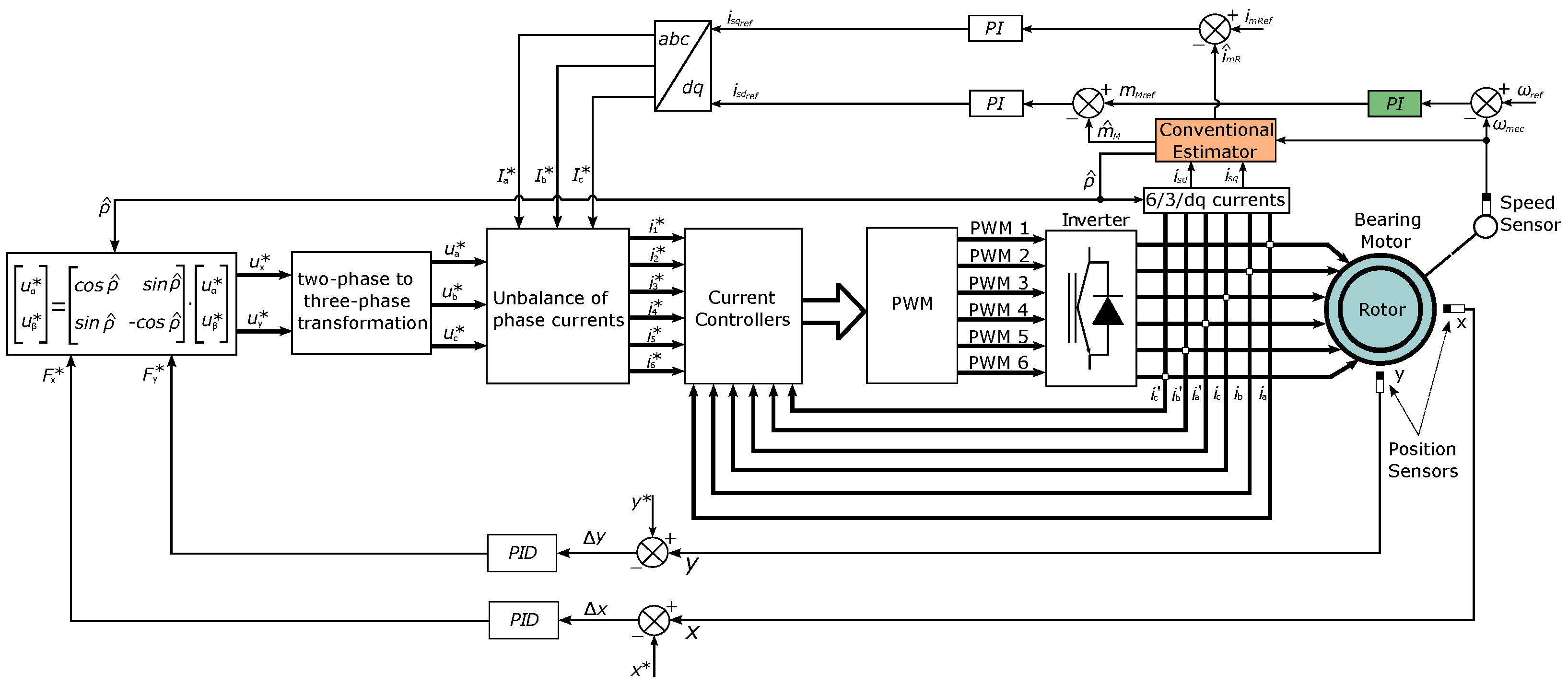
Block diagram of the proposed simulated system.
Figure 1.
Block diagram of the proposed simulated system.
Figure 2.
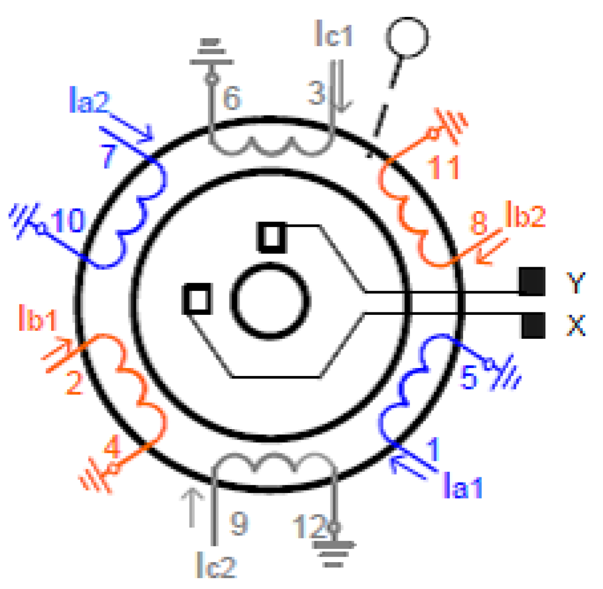
Stator coil layout.
Figure 2.
Stator coil layout.
Figure 3.
Block diagram of the proposed simulated system.
Figure 3.
Block diagram of the proposed simulated system.
Figure 4.
(A) - Fuzzy Sugeno Surface - ANFIS 1 and (B) - ANFIS 2.
Figure 4.
(A) - Fuzzy Sugeno Surface - ANFIS 1 and (B) - ANFIS 2.
Figure 5.
Pertinences before training and after (A) – (B) .
Figure 5.
Pertinences before training and after (A) – (B) .
Figure 6.
Pertinences before training and after (A) – (B) .
Figure 6.
Pertinences before training and after (A) – (B) .
Figure 7.
Comparative result of mechanical speed with estimators.
Figure 7.
Comparative result of mechanical speed with estimators.
Figure 8.
Speed controller error signal.
Figure 8.
Speed controller error signal.
Figure 9.
Electrical torque response operating under simulation conditions.
Figure 9.
Electrical torque response operating under simulation conditions.
Figure 10.
Torque controller error signal.
Figure 10.
Torque controller error signal.
Figure 11.
Angular position result of the rotor flux.
Figure 11.
Angular position result of the rotor flux.
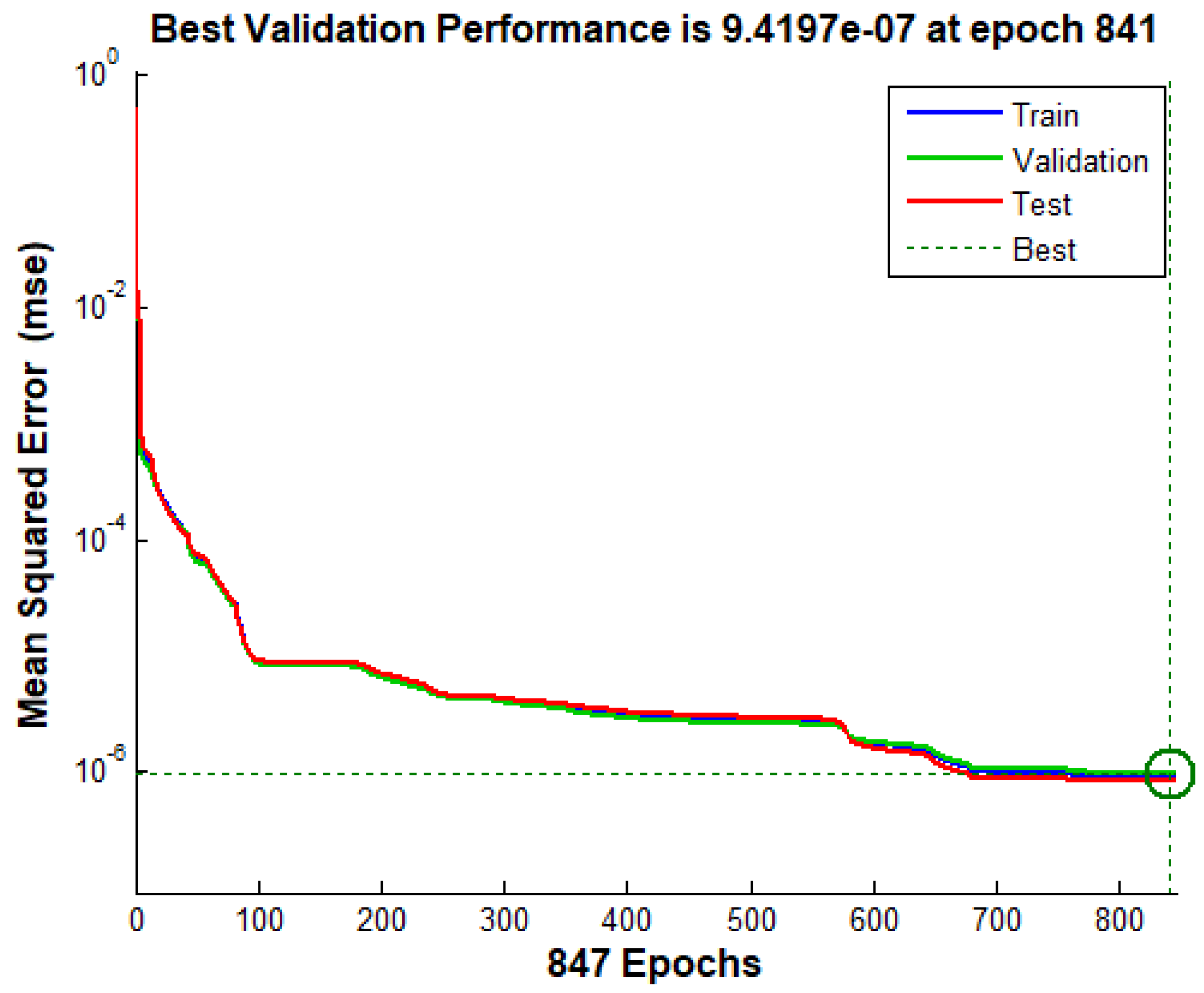
Figure 12.
Mean squared error for training with 847 epochs.
Figure 12.
Mean squared error for training with 847 epochs.
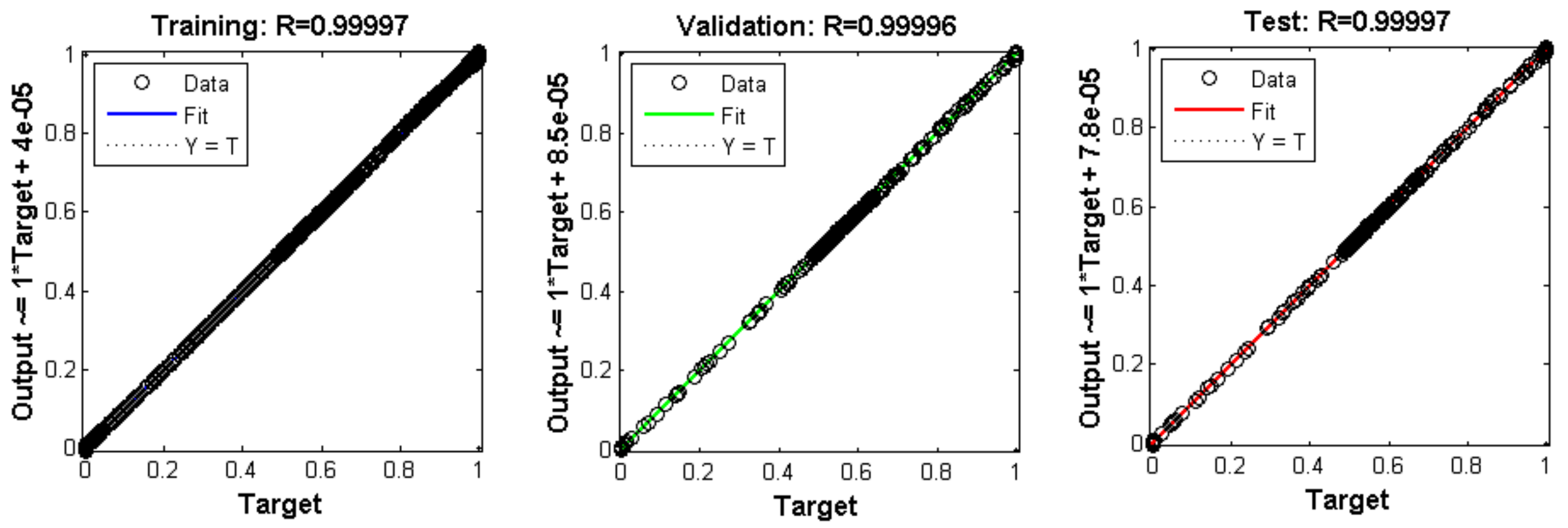
Figure 13.
Results of training (A), validation (B), and Neural Network tests (C).
Figure 13.
Results of training (A), validation (B), and Neural Network tests (C).
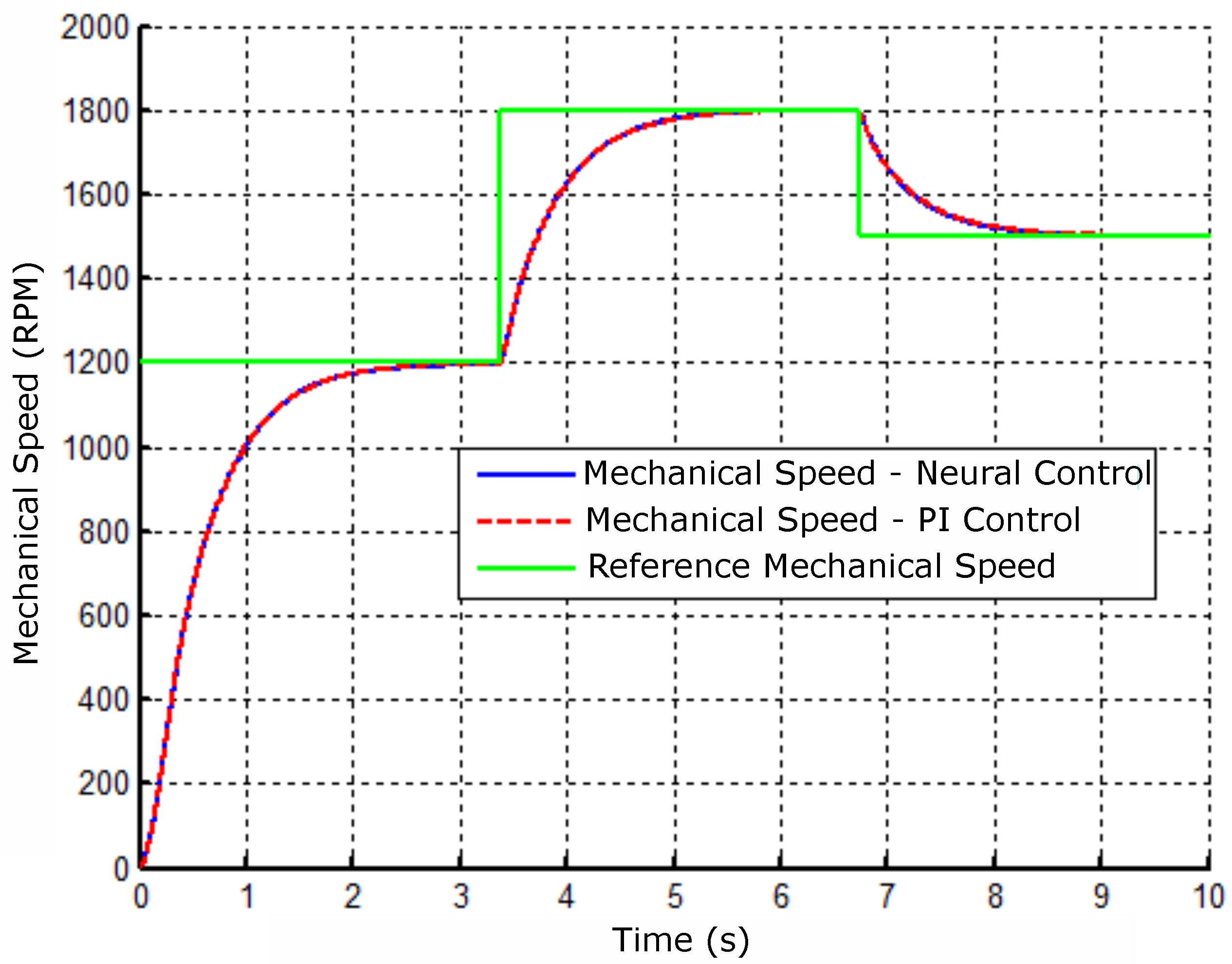
Figure 14.
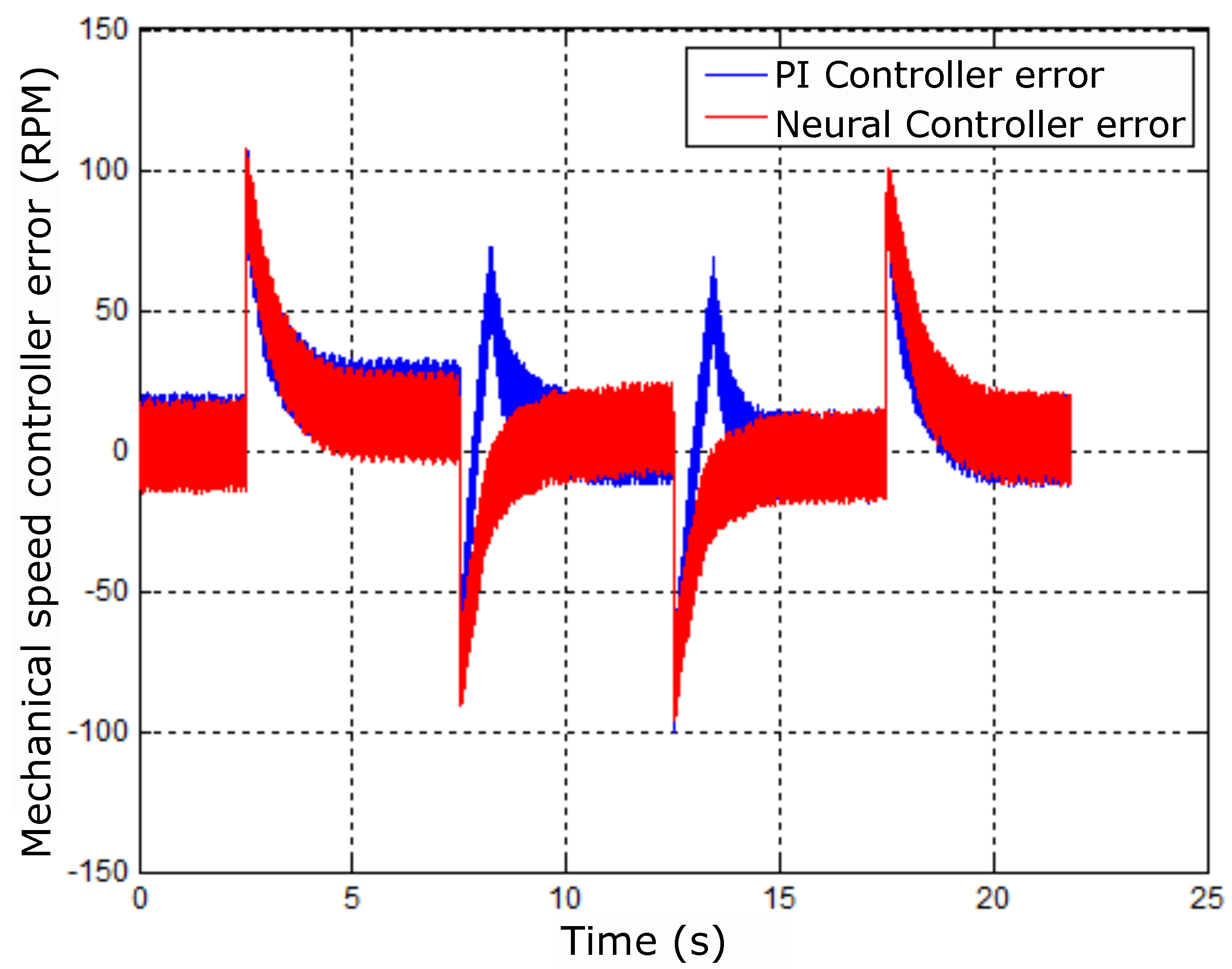
Comparative result of the mechanical speed with the controllers: neural and PI.
Figure 14.
Comparative result of the mechanical speed with the controllers: neural and PI.
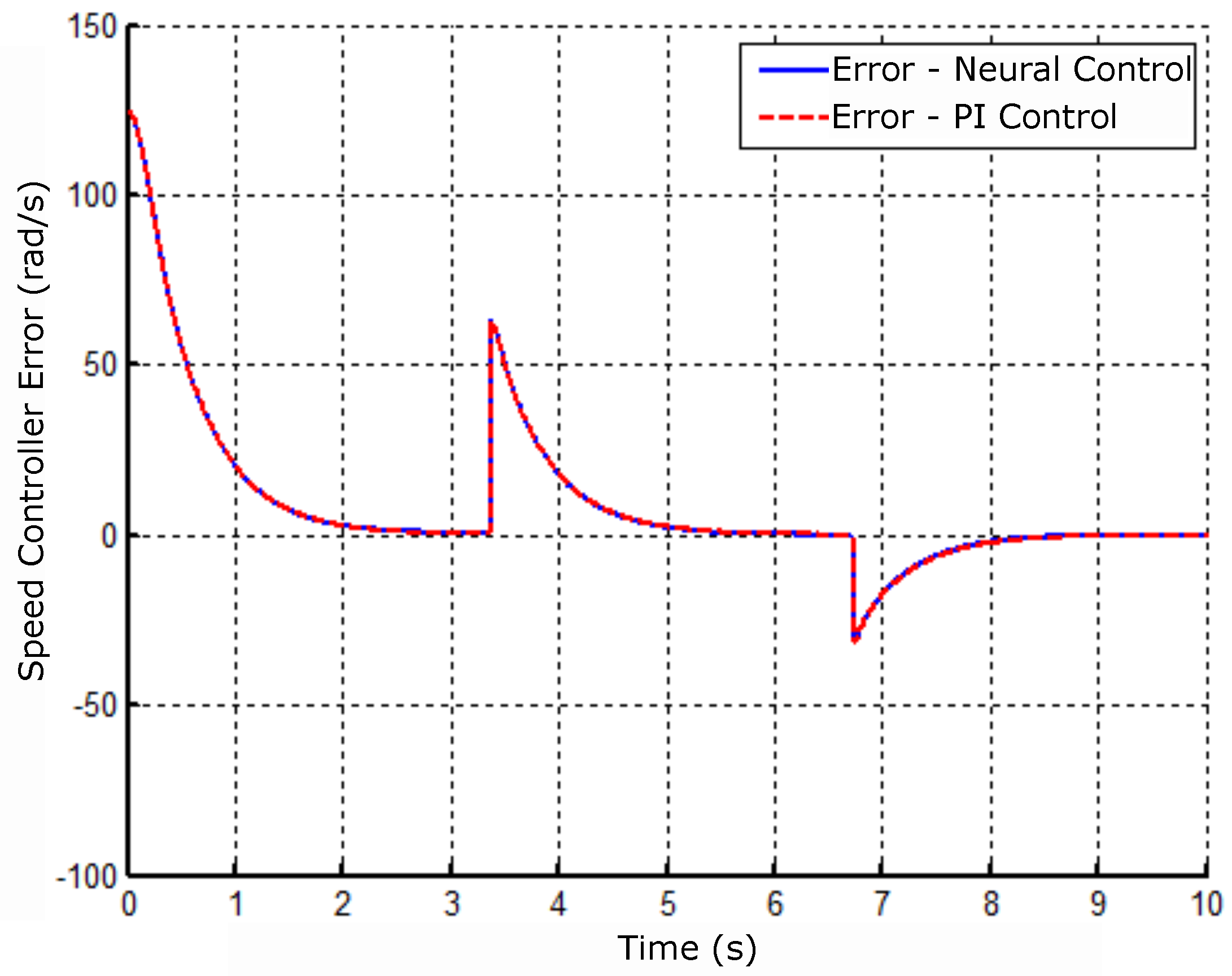
Figure 15.
Neural controller error signal and velocity PI.
Figure 15.
Neural controller error signal and velocity PI.
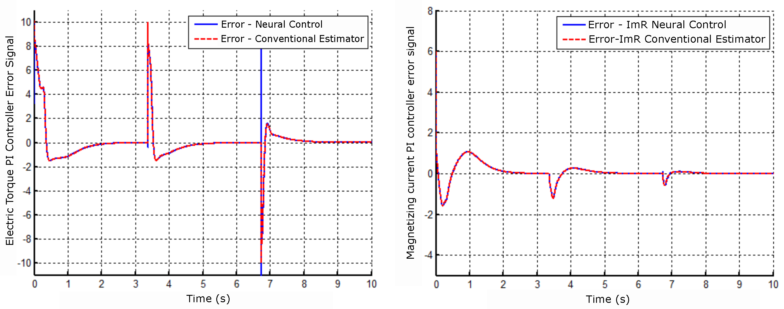
Figure 16.
Controller error signal operating with Neural Network and PI Control (A) - Electric torque and (B) - Magnetizing current.
Figure 16.
Controller error signal operating with Neural Network and PI Control (A) - Electric torque and (B) - Magnetizing current.
Figure 17.
Angular position result of the rotor flux with the neural controller and PI of velocity.
Figure 17.
Angular position result of the rotor flux with the neural controller and PI of velocity.
Figure 18.
Motor-bearing shaft eccentricities. Source: Victor, 2012.
Figure 18.
Motor-bearing shaft eccentricities. Source: Victor, 2012.
Figure 19.
Coverless bearing motor with identification of the coil groups.
Figure 19.
Coverless bearing motor with identification of the coil groups.
Figure 20.
Motor-bearing winding connection arrangement.
Figure 20.
Motor-bearing winding connection arrangement.
Figure 21.
Bearing motor winding connection arrangement. The result identified each coil group according to the sequence of
Figure 20.
Figure 21.
Bearing motor winding connection arrangement. The result identified each coil group according to the sequence of
Figure 20.
Figure 22.
Electronic circuit used with the AEC 5505-04 sensor. Source: [
18].
Figure 22.
Electronic circuit used with the AEC 5505-04 sensor. Source: [
18].
Figure 23.
Unwanted and desired radial displacement for position control.
Figure 23.
Unwanted and desired radial displacement for position control.
Figure 24.
(A) Radial displacement reaping in the Y coordinate and (B) the sensor signals X (green) and Y (yellow) in oscilloscope free mode.
Figure 24.
(A) Radial displacement reaping in the Y coordinate and (B) the sensor signals X (green) and Y (yellow) in oscilloscope free mode.
Figure 25.
Behavior of the signals after adjusting the offset of the sensors.
Figure 25.
Behavior of the signals after adjusting the offset of the sensors.
Figure 26.
Radial displacement limit of the rotor.
Figure 26.
Radial displacement limit of the rotor.
Figure 27.
Mechatronic system with interfaces and the bearing motor.
Figure 27.
Mechatronic system with interfaces and the bearing motor.
Figure 28.
Control structure with flux estimator.
Figure 28.
Control structure with flux estimator.
Figure 29.
Bearing motor cascade control diagram.
Figure 29.
Bearing motor cascade control diagram.
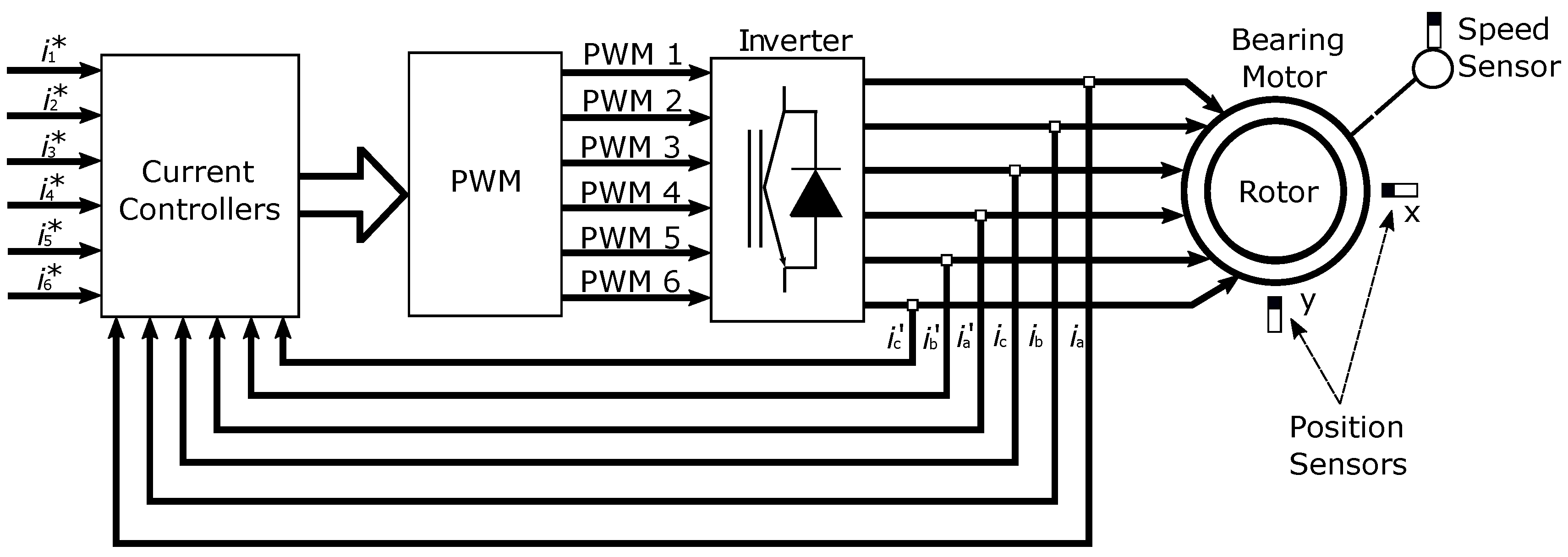
Figure 30.
Motor-bearing current control.
Figure 30.
Motor-bearing current control.
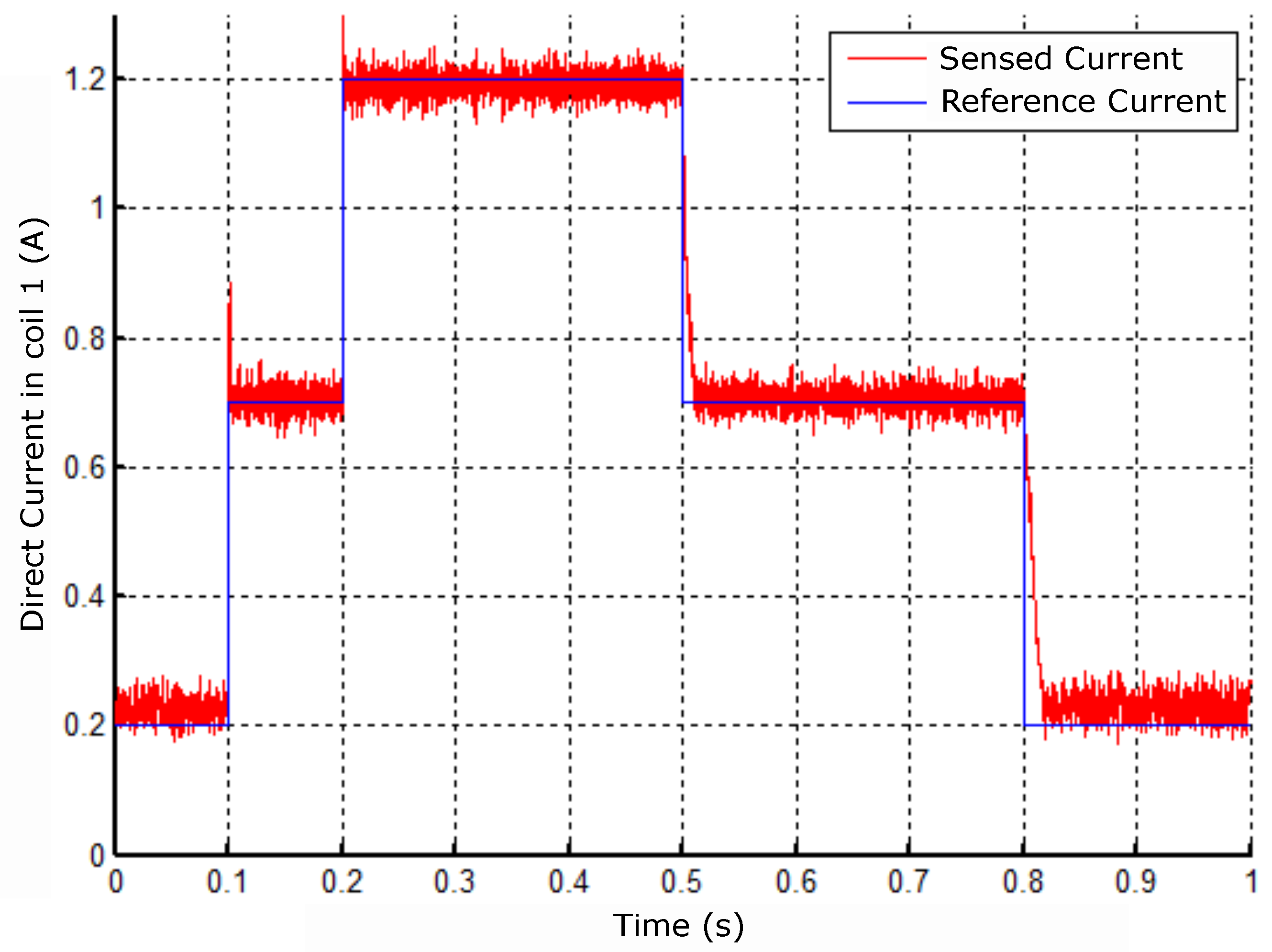
Figure 31.
Response to the reference change in coil 1.
Figure 31.
Response to the reference change in coil 1.
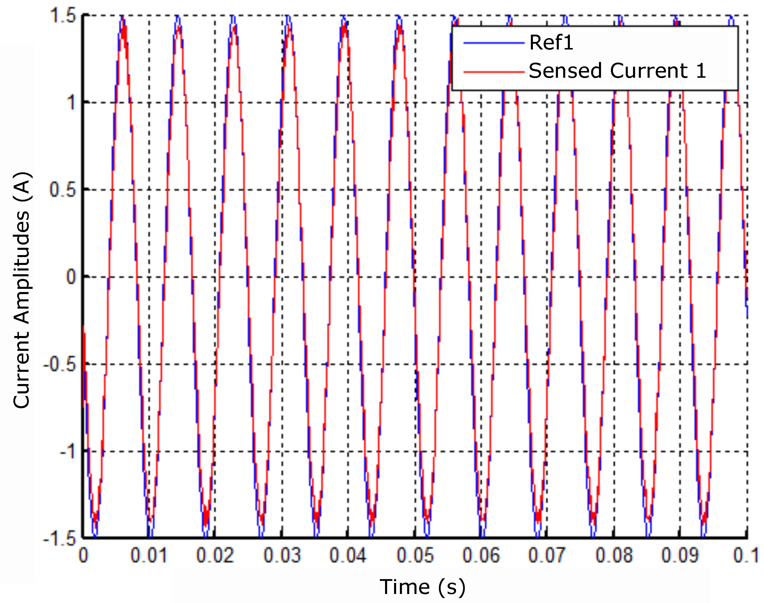
Figure 32.
Response to sinusoidal reference in coil 1.
Figure 32.
Response to sinusoidal reference in coil 1.
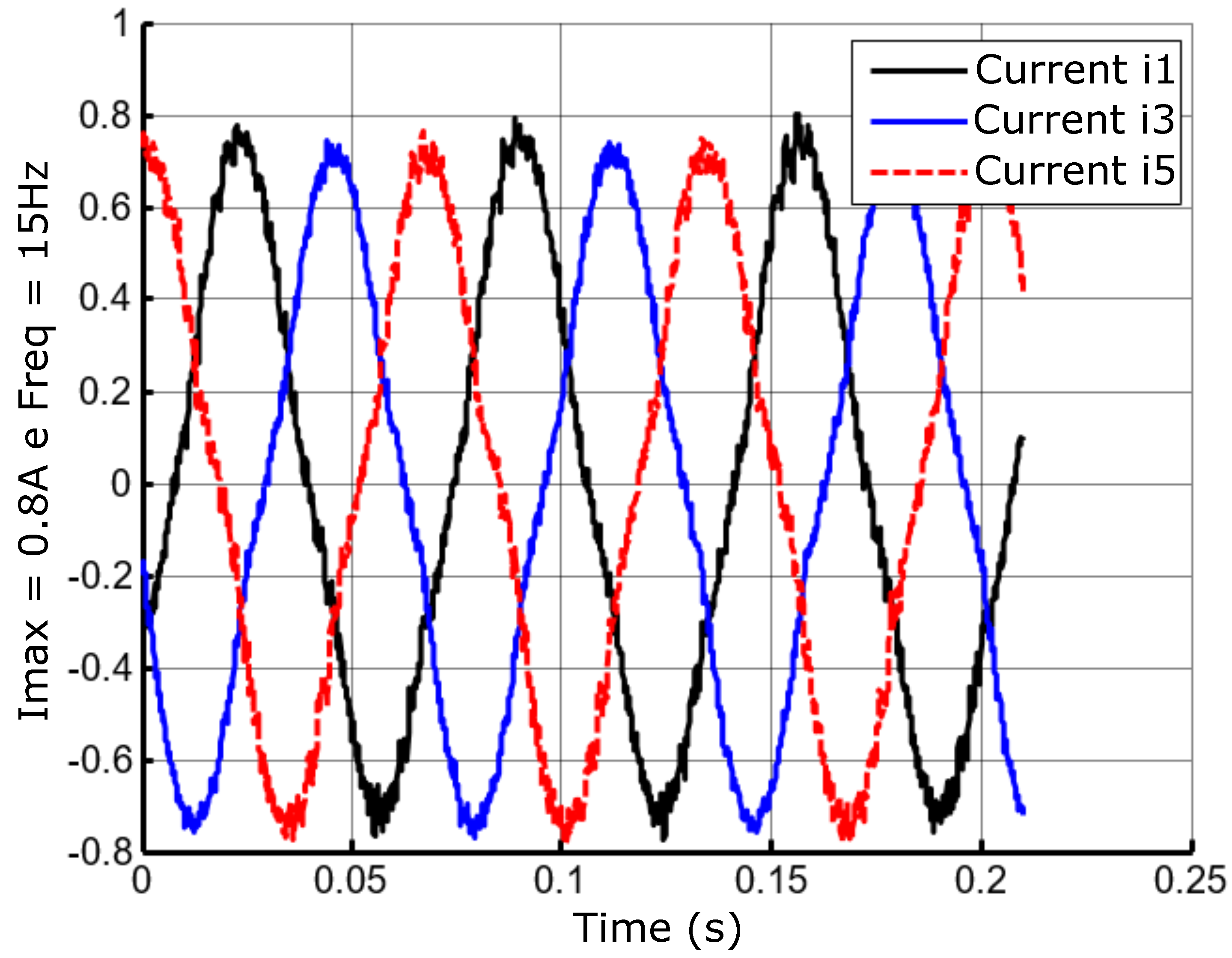
Figure 33.
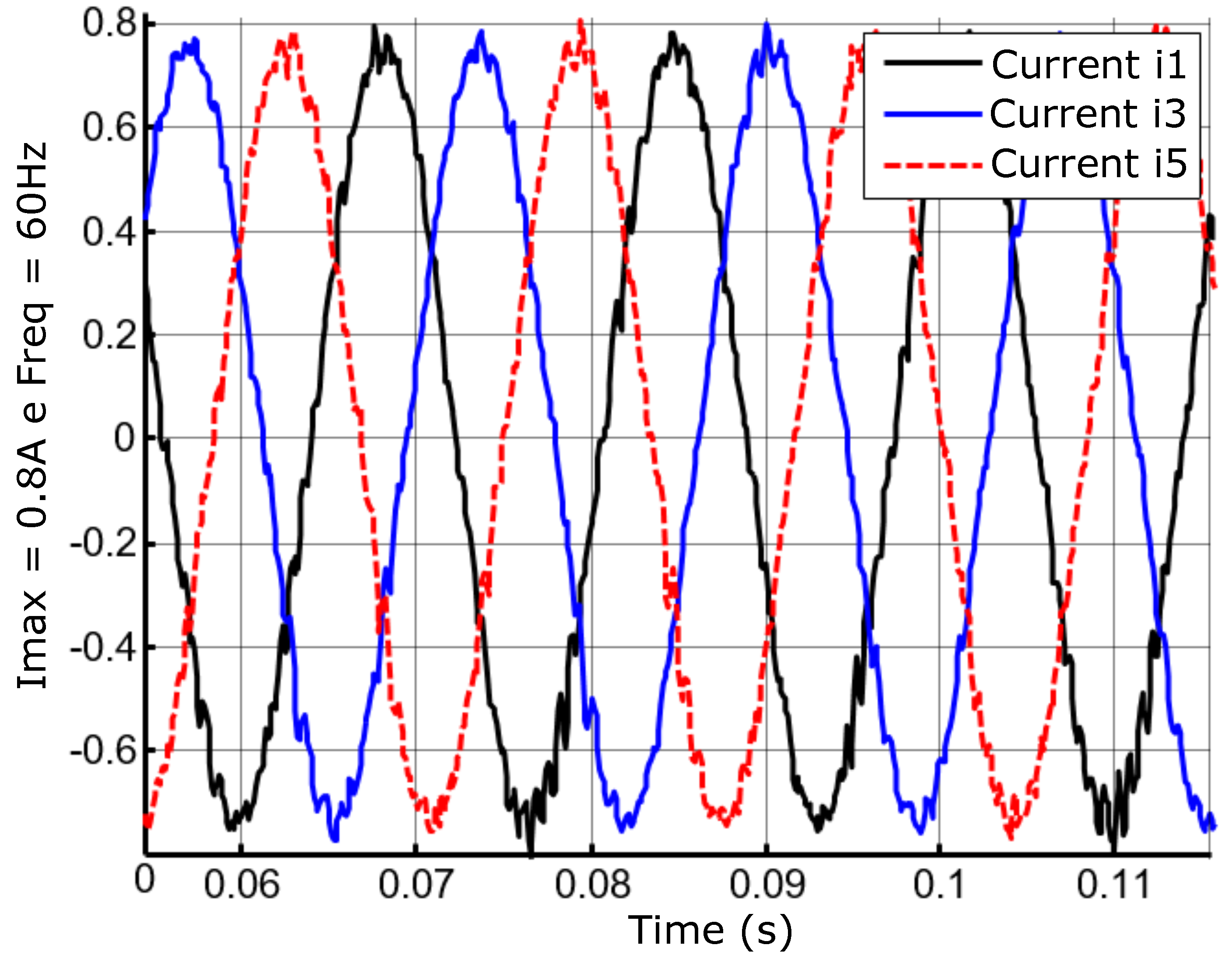
Lagged currents at 15Hz frequency and A amplitude.
Figure 33.
Lagged currents at 15Hz frequency and A amplitude.
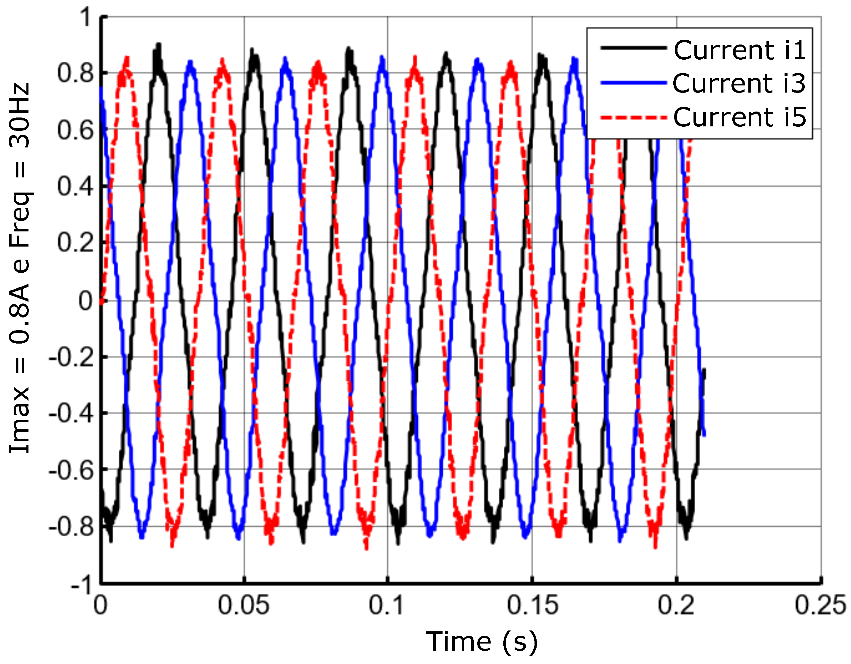
Figure 34.
Lagged currents at the frequency of 30Hz and amplitude A.
Figure 34.
Lagged currents at the frequency of 30Hz and amplitude A.
Figure 35.
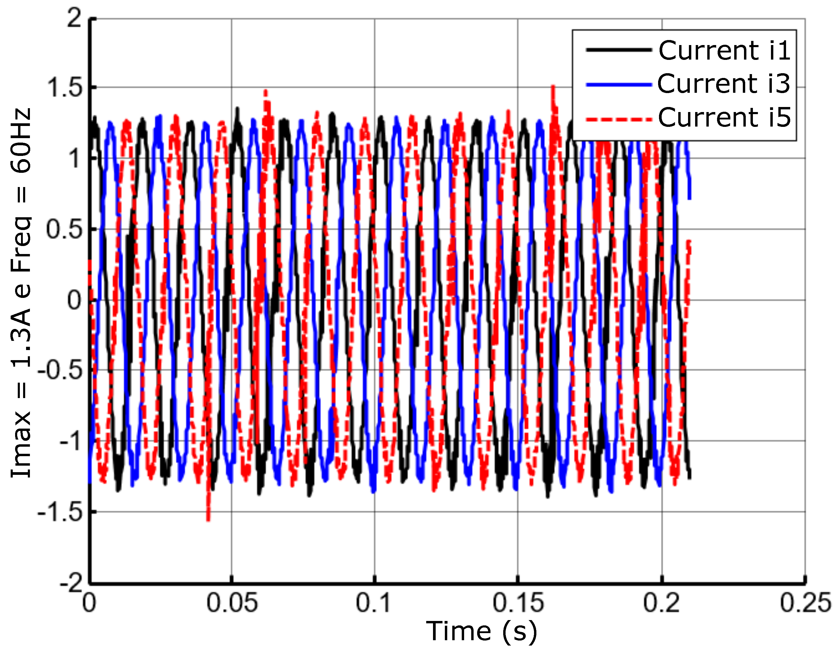
Lagged currents at the frequency of 60Hz and amplitude A.
Figure 35.
Lagged currents at the frequency of 60Hz and amplitude A.
Figure 36.
Lagged currents at the frequency of 60Hz and amplitude A.
Figure 36.
Lagged currents at the frequency of 60Hz and amplitude A.
Figure 37.
Cascade position control with motor-bearing current control.
Figure 37.
Cascade position control with motor-bearing current control.
Figure 38.
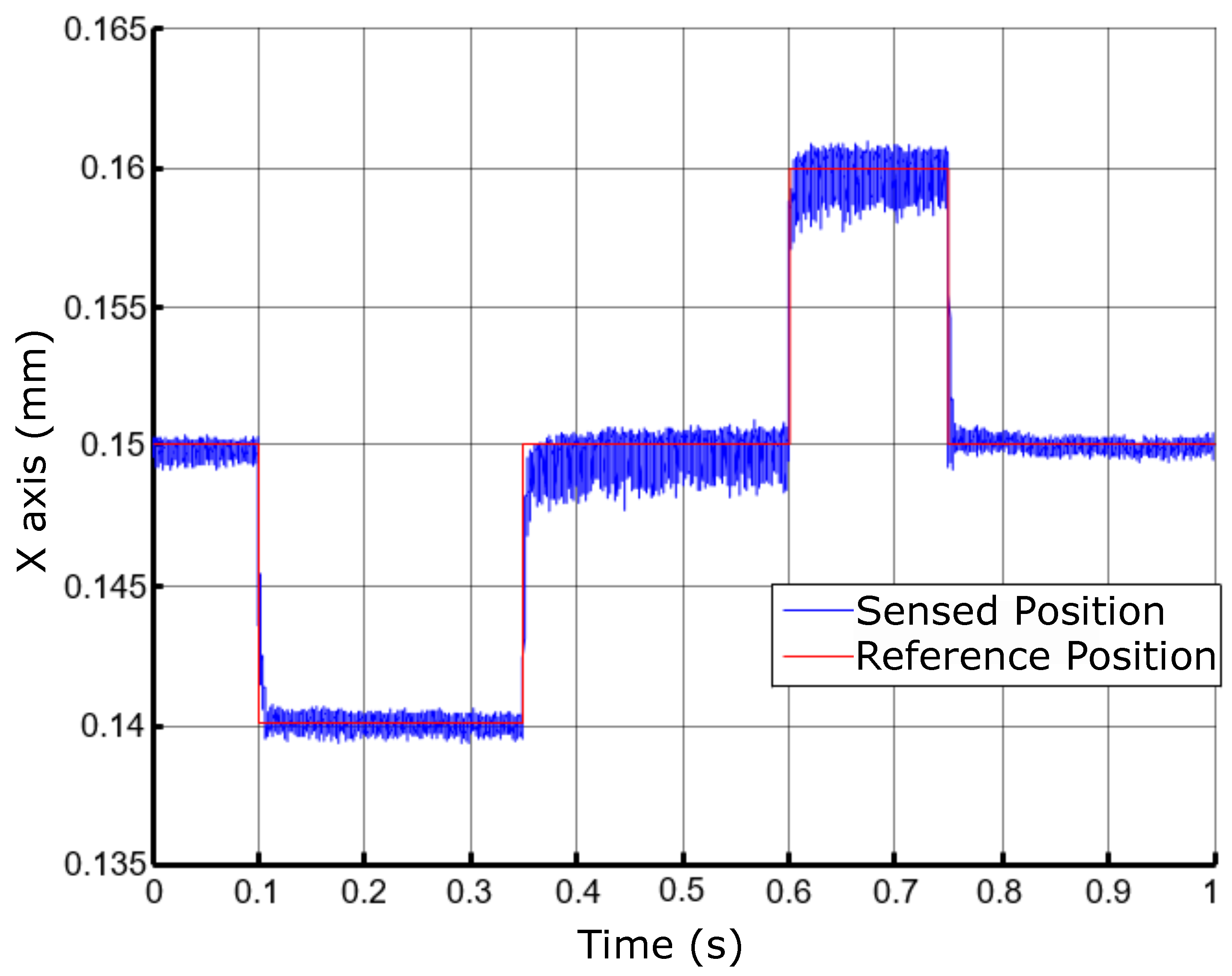
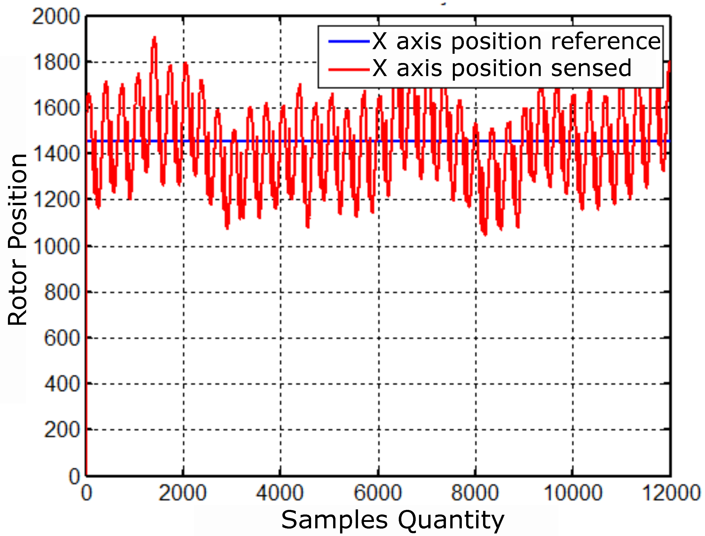
Position control results for the X axis.
Figure 38.
Position control results for the X axis.
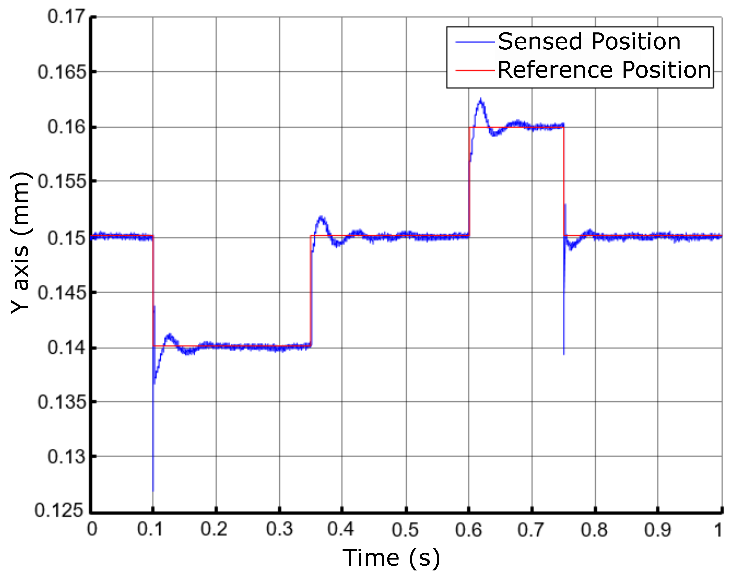
Figure 39.
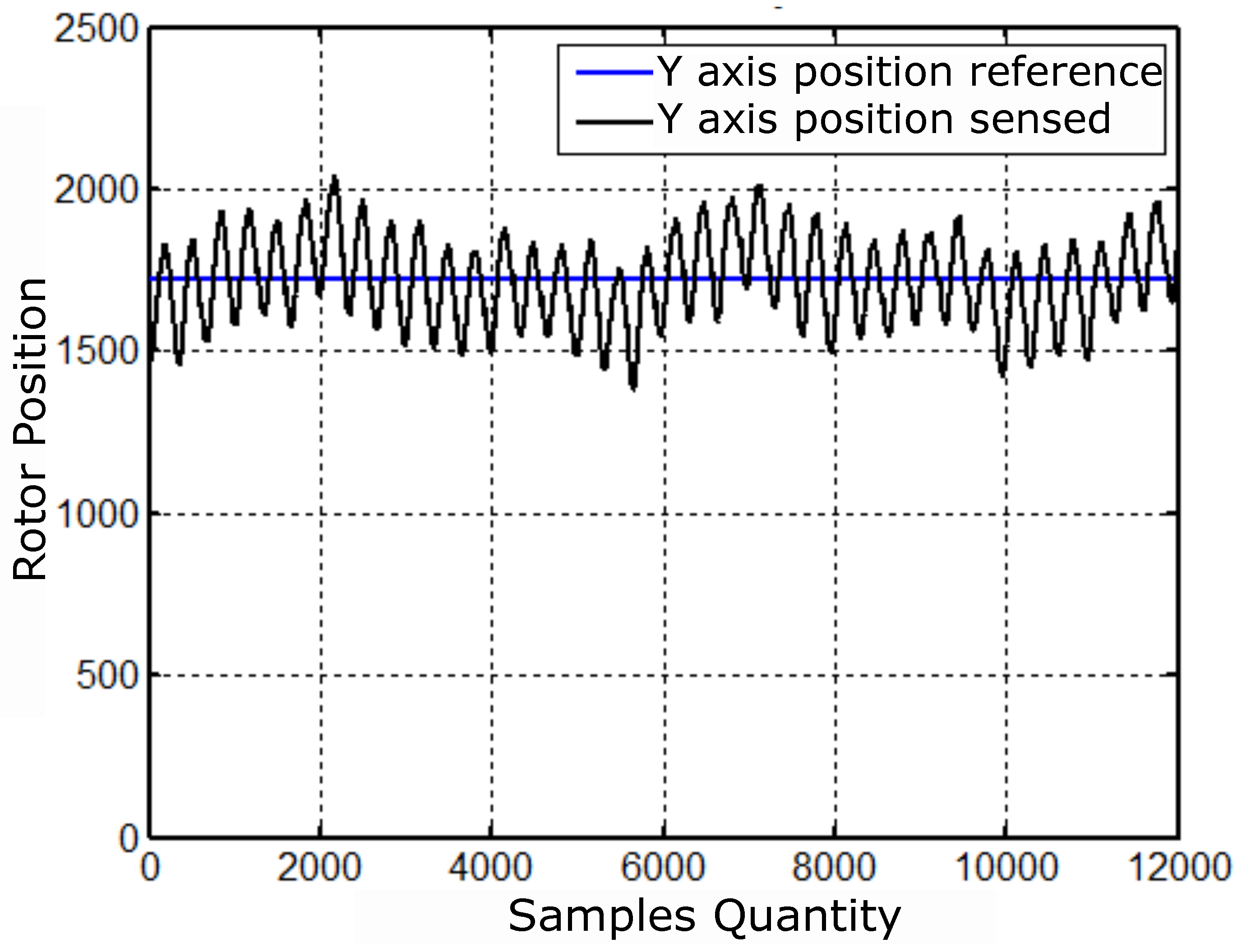
Position control results for the Y axis.
Figure 39.
Position control results for the Y axis.
Figure 40.
Position control results with a rotor scatter area for activation at 60Hz.
Figure 40.
Position control results with a rotor scatter area for activation at 60Hz.
Figure 41.
Position control results with an area of dispersion from the rotor to the 15Hz drive.
Figure 41.
Position control results with an area of dispersion from the rotor to the 15Hz drive.
Figure 42.
Position control results with an area of dispersion from the rotor to the activation at 30 Hz.
Figure 42.
Position control results with an area of dispersion from the rotor to the activation at 30 Hz.
Figure 43.
Position control results with an area of dispersion from the rotor to the 45Hz drive.
Figure 43.
Position control results with an area of dispersion from the rotor to the 45Hz drive.
Figure 44.
Radial displacements of the X-axis driven at 60Hz.
Figure 44.
Radial displacements of the X-axis driven at 60Hz.
Figure 45.
Radial displacements of the Y-axis driven at 60Hz.
Figure 45.
Radial displacements of the Y-axis driven at 60Hz.
Figure 46.
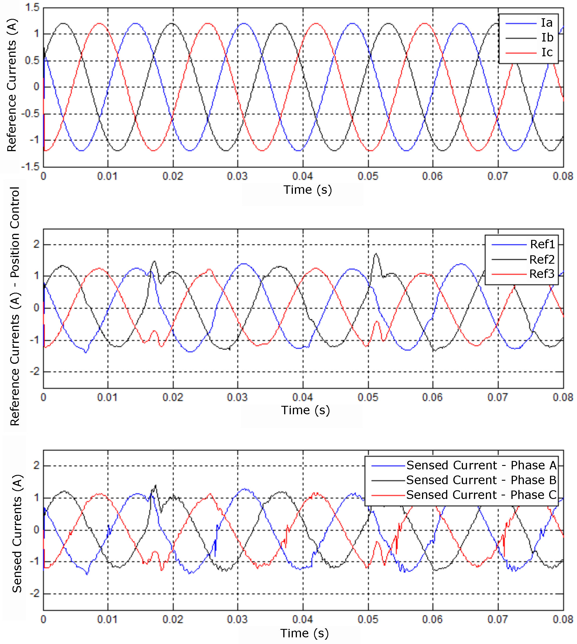
Results referring to imposed, controlled and sensed currents.
Figure 46.
Results referring to imposed, controlled and sensed currents.
Figure 47.
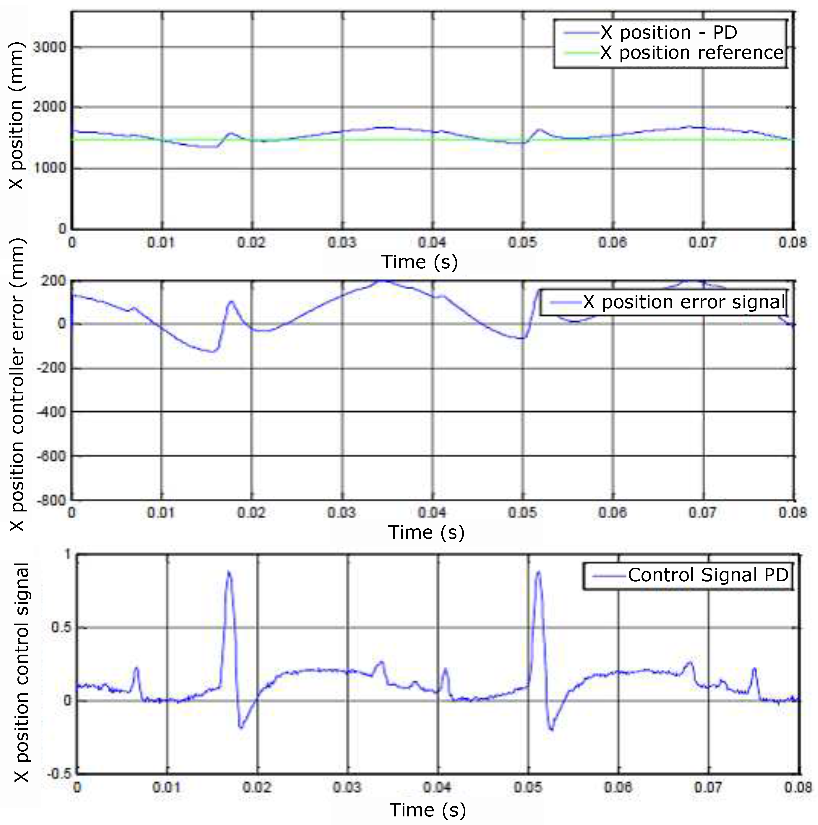
(A) X position, (B) controller error, and (C) control signals.
Figure 47.
(A) X position, (B) controller error, and (C) control signals.
Figure 48.
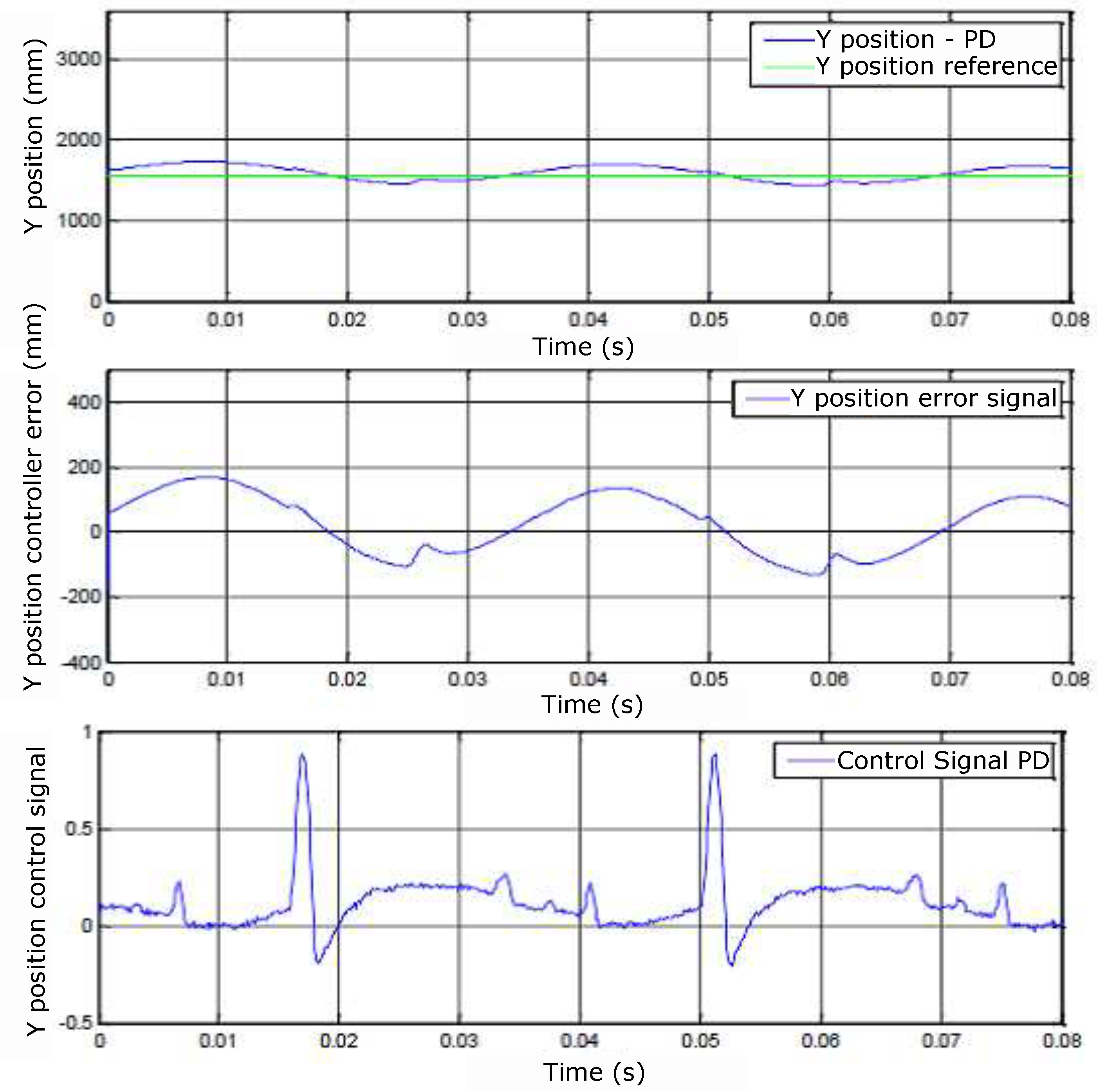
(A) Y position, (B) controller error and (C) control signals.
Figure 48.
(A) Y position, (B) controller error and (C) control signals.
Figure 49.
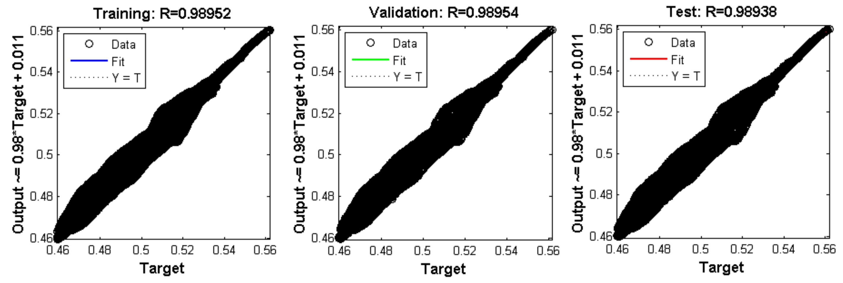
Result of training, validation, and testing of the Neural Network.
Figure 49.
Result of training, validation, and testing of the Neural Network.
Figure 50.
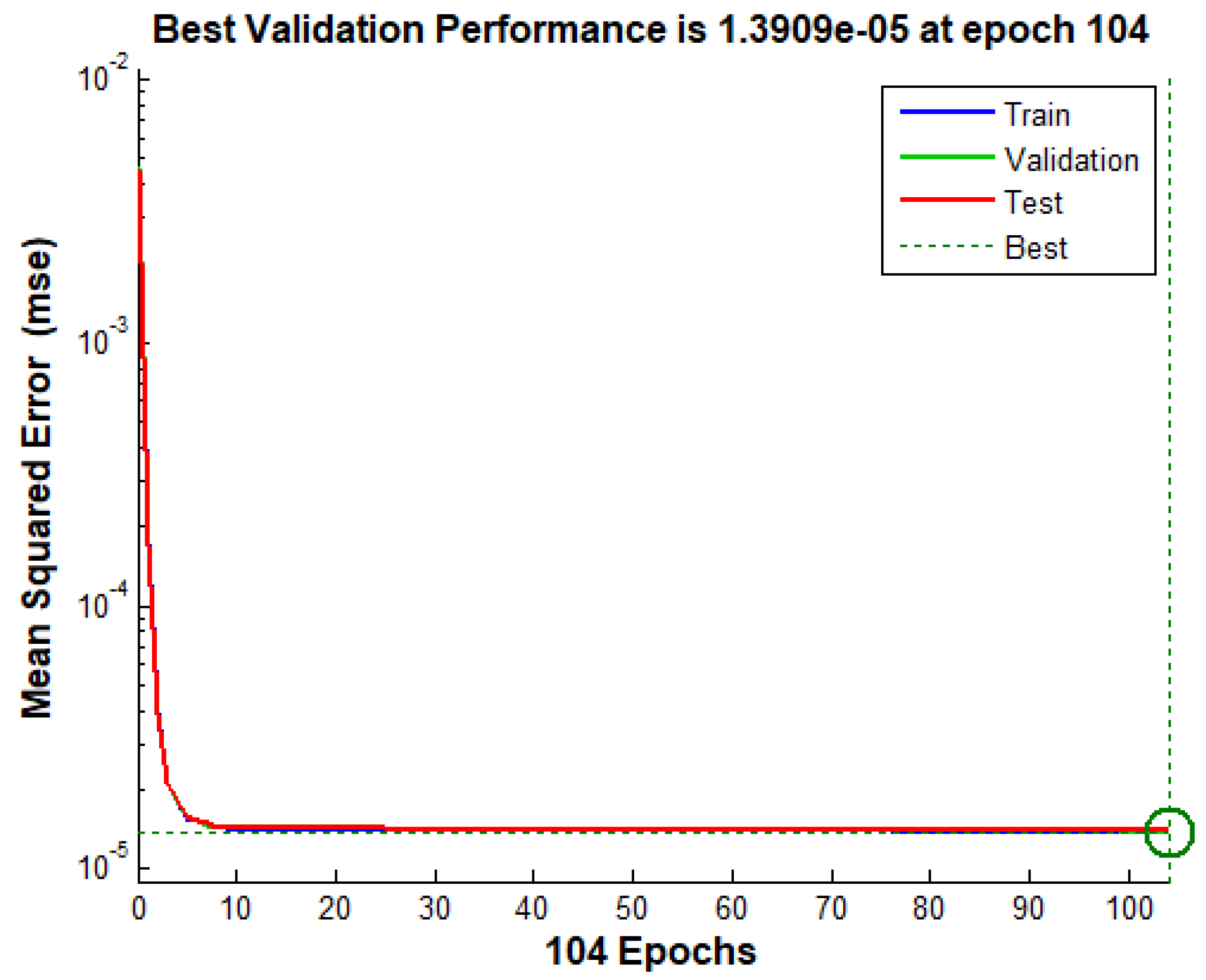
Mean squared error for training with 104 epochs.
Figure 50.
Mean squared error for training with 104 epochs.
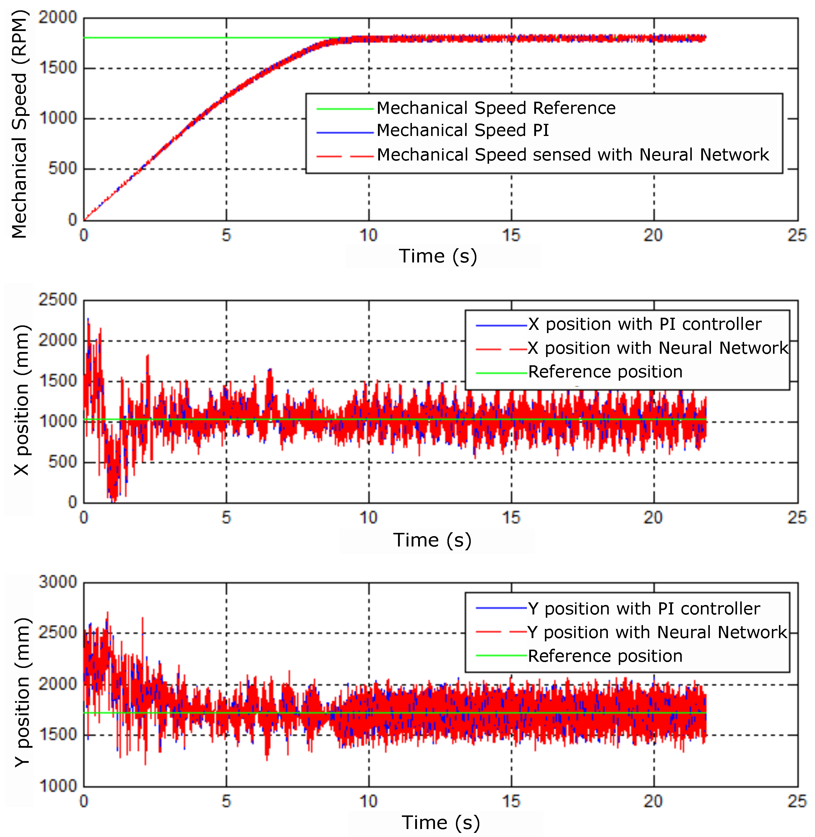
Figure 51.
Mechanical speeds and X and Y positions for step speed reference constant.
Figure 51.
Mechanical speeds and X and Y positions for step speed reference constant.
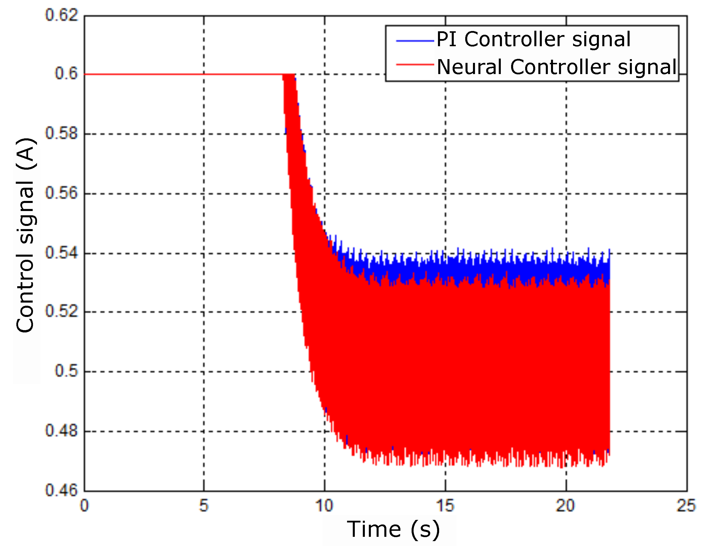
Figure 52.
PI and neural control signals for step speed reference.
Figure 52.
PI and neural control signals for step speed reference.
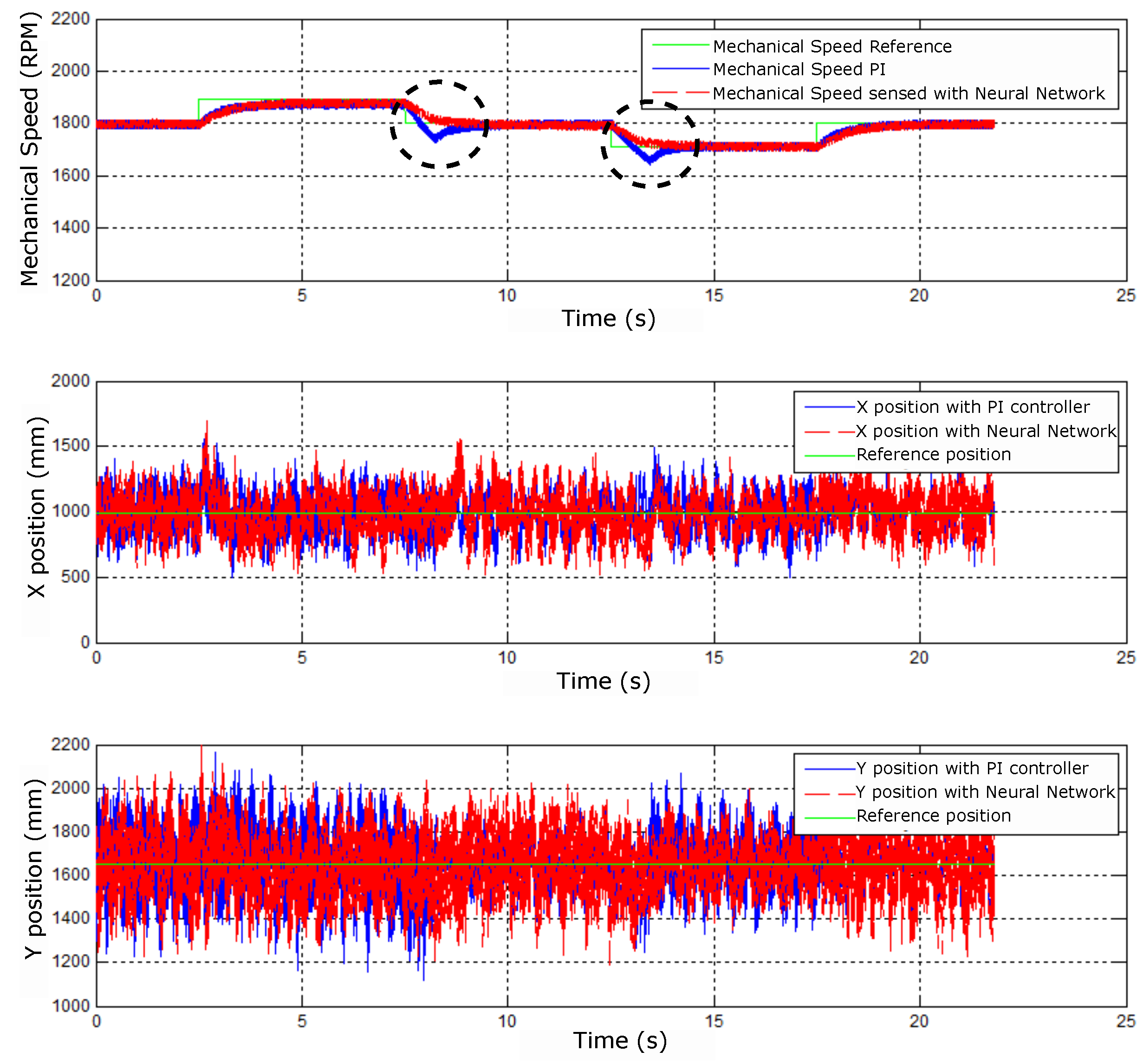
Figure 53.
Mechanical speed and X and Y positions for step speed reference.
Figure 53.
Mechanical speed and X and Y positions for step speed reference.
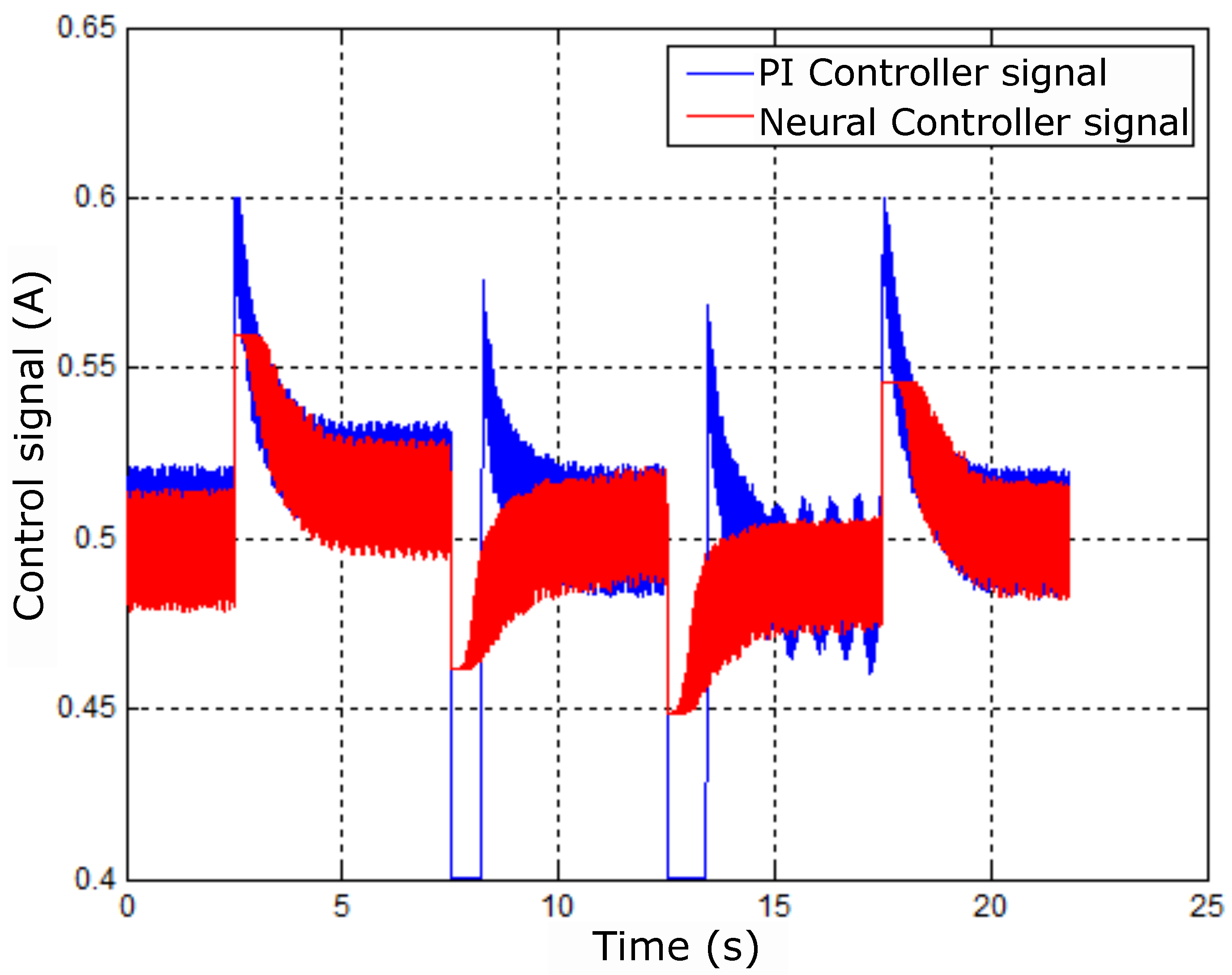
Figure 54.
Control signals for step speed reference.
Figure 54.
Control signals for step speed reference.
Figure 55.
Control error signals for step speed reference.
Figure 55.
Control error signals for step speed reference.
Figure 56.
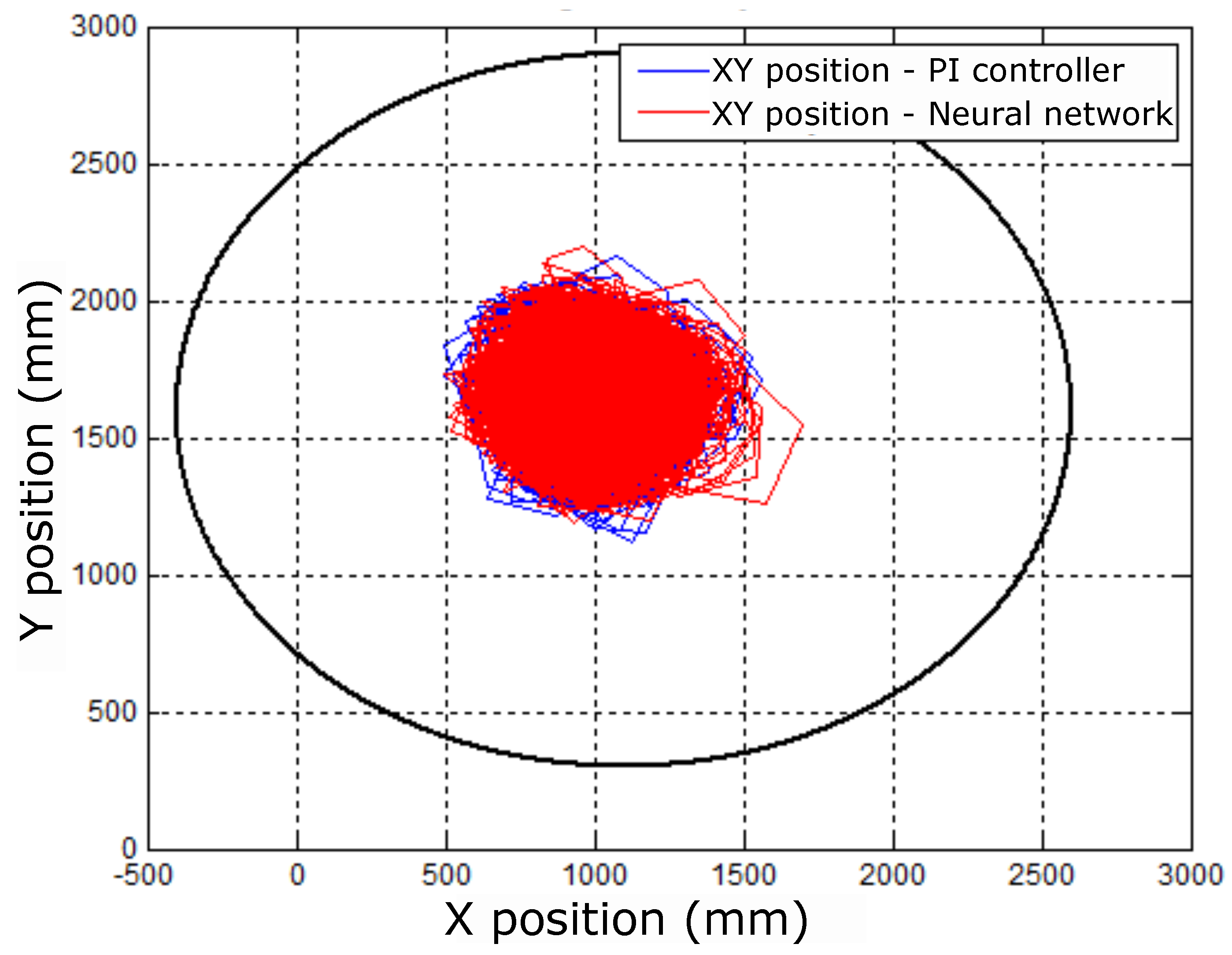
Radial positioning diagrams for step speed reference.
Figure 56.
Radial positioning diagrams for step speed reference.
Figure 57.
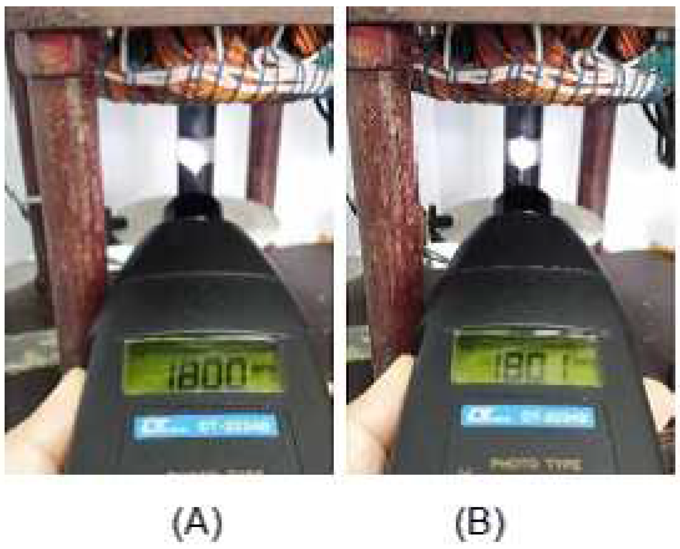
Mechanical velocity measurement (A) PI control and (B) neural control.
Figure 57.
Mechanical velocity measurement (A) PI control and (B) neural control.
Table 1.
Engine Parameters and Characteristics.
Table 1.
Engine Parameters and Characteristics.
| Symbols |
Description |
Values |
| Pnom |
Rated power |
3.70 kW |
| Wmec |
Rated Speed |
1715 RPM |
| Tnom |
Rated voltage |
380 V |
| Np |
Pole Pair Number |
2 |
| R1 |
Stator Resistance |
1.182
|
| R2 |
Rotor Resistance |
1.42
|
| J |
Inertia moment |
0.00995 kg.
|
| Ls |
Stator Inductance |
6.56 mH |
| Lr |
Rotor Inductance |
6.56 mH |
| Lm |
Magnetization Inductance |
0.14 H |
|
Core loss |
891.2
|
|
Gap size |
0.25 mm |
Table 2.
Parameters of PI Controllers used in tuning.
Table 2.
Parameters of PI Controllers used in tuning.
| PI |
kpw |
kiw |
kpmM |
kimM |
kpimR |
kiimR |
| (1) |
10.7 |
50 |
1 |
10 |
2 |
50 |
| (2) |
6 |
60 |
2 |
100 |
2 |
15 |
| (3) |
1 |
10 |
2 |
50 |
1 |
30 |
Table 3.
Controller Parameters.
Table 3.
Controller Parameters.
| Controller
Proportional-Full |
Parameters |
Values |
| Torque |
KpmM |
1 |
| Torque |
KimM |
100 |
| Magnetizing Current |
KpimR |
2 |
| Magnetizing Current |
KiimR |
50 |
Table 4.
ANFIS 1 Parameters.
Table 4.
ANFIS 1 Parameters.
| Pertinence functions |
Epoach |
training error |
validation error |
| 2 |
50 |
0.0558002 |
0.00813261 |
| 3 |
150 |
0.0488926 |
0.00815185 |
| 3 |
300 |
0.0409925 |
0.01109080 |
| 5 |
500 |
0.00175787 |
0.00781050 |
Table 5.
ANFIS 2 Parameters.
Table 5.
ANFIS 2 Parameters.
| Pertinence functions |
Epoach |
training error |
validation error |
| 2 |
50 |
0.00406290 |
0.00489893 |
| 3 |
150 |
0.00533958 |
0.7491140 |
| 3 |
300 |
0.00448118 |
0.3522810 |
| 5 |
400 |
0.00359959 |
0.3302490 |
Table 6.
Neural Network Parameters.
Table 6.
Neural Network Parameters.
| Network Architecture |
Multilayer Perceptron |
| Training type |
Supervised - offline |
| Layers number |
3 |
| Input layer neurons |
3 |
| 1st hidden layer neurons |
10 |
| Output layer neurons |
1 |
| Training algorithm |
Levenberg-Marquardt backpropagation |
| Learning rate |
5
|
| Epochs number |
841 |
| Training error |
9.4197
|
| Hidden layer activation function |
Hyperbolic tangent |
| Output layer activation function |
Linear |
Table 7.
Engine prototype parameters.
Table 7.
Engine prototype parameters.
| Parameters |
Values |
| Rated power |
1 Hp[hp] |
| Frequency |
60 Hz |
| Poles numbers |
4 |
| Rated voltage |
220/380 V |
| Rated current |
3.02/1.75 A |
| Empty current |
1.90 A |
| No load power |
160.00 W |
| Resistance |
7.38 Ohms |
| Stator Resistance per Phase |
0.73 Ohms |
Table 8.
Neural Network Parameters.
Table 8.
Neural Network Parameters.
| Network Architecture |
Multilayer Perceptron |
| Type of training |
Supervised - offline |
| Number of layers |
3 |
| Input layer neurons |
2 |
| 1st hidden layer neurons |
10 |
| Output layer neurons |
1 |
| Training algorithm |
Levenberg-Marquardt backpropagation |
| Learning rate |
5
|
| Epoch number |
104 |
| Training error |
1.3909
|
| Hidden layer activation function |
Hyperbolic tangent |
| Output layer activation function |
Linear |
