Preprint
Article

Sustainability Evaluation of Hybrid Agriculture Tractors Powertrains

Altmetrics

Downloads

133

Views

48

Comments

0

A peer-reviewed article of this preprint also exists.

Submitted:

03 January 2024

Posted:

04 January 2024

You are already at the latest version

Alerts
Abstract
Agricultural tractors are high fuel-consuming and polluting machines, thus the introduction of new sustainable technologies, as hybridization, can be very impactful for the development of electric hybrid agricultural tractors. These vehicles combine the classic internal combustion engine with an electric machine, to reduce the environmental impact and improve the efficiency. This paper reports the modeling and the simulation conducted, using a simulation software typically used for on-road vehicles, of a two wheel-drive agricultural tractor in three different configurations: the conventional one, the series and the parallel electric hybrid powertrain. The simulated task is the trailing of a big square baler during the process of straw wrapping and baling. The evaluation and the comparison of the fuel consumption, CO2 emissions and the depth of discharge of the different configurations has been carried out to determine if it is possible to downsize the ICE, maintaining the same performances. This study points out that the hybridization of agricultural tractors powertrains is one of the most promising approaches to reduce pollutant emissions and fuel consumption.
Keywords: 
Subject: Environmental and Earth Sciences  -   Environmental Science

1. Introduction

The extensive use of hydrocarbon fuels, employed to power a variety of agricultural machinery, including tractors and harvesters, adversely effects the environment and significantly reduces air quality [1]. Agricultural tractors are the most fuel-consuming and polluting machines. Agricultural sector accounts for almost the 10% of the annual EU27 production of greenhouse gas (GHG) [2,3]. Elevated levels of carbon dioxide (CO2) emissions are considered one of the causes of global warming [4]; each liter of burnt diesel fuel, produces as much as 2.7 kg of CO2 [5]. Vehicles with internal combustion engines (ICEs) are the major contributors to pollutant emissions. In the agricultural sector, diesel engines represent the most widely adopted powertrain [6]. Based on our knowledge, most of the studies present results on fuel consumption when some bio-based products have been added [7,8,9] or evaluate the emissions of agricultural machines fixing the ICE parameters [10,11,12]. In real field operations these parameters usually change their values, few studies analyze the performances of tractors during the execution of some real agricultural tasks [13,14,15] but there are no reference values about the pollutant emissions generated.
The monitoring of the performance and exhaust emissions of agricultural tractors expensive and time-consuming because it requires field measures. Thus, it is necessary to exploit new methodologies that, using the manufacturers’ data and measured field data, allow to automatically calculate and monitor the fuel consumption and the emissions of exhaust gases [16]. These indicators strictly depend on the agricultural task, the engine working point and the load at the PTO [17,18,19].
In the past decade, stringent emission standards have been introduced for Non-Road Mobile Machineries (NRMM), including agricultural tractors [20]. To comply with these regulations, tractor manufacturers have integrated technologies aimed at filtering particulate matter from the exhaust system, such as exhaust aftertreatment systems and particulate filters [21]. However, these approaches are characterized by high costs, significant spatial requirements, and an inability to completely mitigate the issue. Consequently, NRMM manufacturers are now exploring novel sustainable methodologies and technologies [22,23] to curtail emissions and decrease fossil fuel consumption. The primary objective is reducing environmental impact sustainably, simultaneously enhancing overall machine efficiency.
Among the sustainable technologies for the agricultural sector, the development of hybrid electric tractors offers promising prospects. This approach will represent the predominant direction in the development of NRMM drive systems in the near future [24,25,26]. Integrating a conventional ICE engine with an electric drive system alighns with the principles of sustainable agriculture, protecting the environment and promote ecological food production.
Hybrid electric tractors can ensure:
  • Improved Efficiency: The integration of an electric powertrain allows a more precise control of energy usage, optimizing the tractor’s performance during farming operations;
  • Fuel Savings: The reduced reliance on fossil fuels by harnessing electric power, leading to significant fuel savings and cost reduction;
  • Lower Emissions: The emission of fewer pollutant exhaust and GHG during operations, contributing to a cleaner and more sustainable farming practice;
  • Flexibility: The tractor can switch between the ICE and the electric power source, allowing the farmers to adapt their employment to different workloads and working conditions;
  • Reduced Noise and Vibrations: The electric motor operates quietly, reducing noise pollution in rural areas and improving the working environment;
  • Less Maintenance Costs: The tractor have far lower maintenance requisites than the diesel counterparts because they have fewer mechanical parts, reducing the chance to break down;
  • Safety and Stability: These tractors have a center of gravity positioned lower than the diesel counterparts, reducing the likelihood of their toppling or rolling over uneven terrains;
The implementation of hybrid drive systems in agricultural tractors is in the initial phase, therefore there are still a number of technological limitations. Solving these problems will enable the development of mass-scale production of hybrid tractors.[20]. Firstly, tractors are very versatile agricultural machines, they can perform a variety of operations such as ploughing, soil tillage, fertilizing, and transport, which demand different levels of power and loads, so their power range is very wide, from few tens of kW up to hundreds kW.
Furthermore, high technological and production costs, combined with the lack of efficient Energy Storage Systems (ESSs), do not allow the spreading of hybrid electric tractors [27]. The battery's energy density is a factor of 100 less than the diesel’s energy density [28]. This aspect implies that, also in the future, agricultural tractors will still be powered by an ICE, combined with an electric drive in a hybrid configuration.
The traditional method of assessing tractor performance, fuel consumption and pollutant emissions involves expensive and time-consuming field tests. Advanced technologies enable replacing some of these experiments with computer simulation which assures the reliability of the results.
Therefore, the employment of a simulation software in the modelling and design phase of an agricultural tractor can be very impactful [29]. Simulation tools enables creating digital twins of the vehicle, which represent the virtual prototype that replicate the behavior of the real machine [30]. Moreover, simulation models are very important because they make it possible to test the machine under a variety of working conditions, looking in real-time the effects of some design modifications in the powertrain configuration, avoiding the creation of expensive physical prototypes. One of the principles of creating numerical simulation models is to ensure that the model is as flexible and reusable as possible.
To our knowledge, the use of simulation software in the agricultural sector, to model and evaluate the performance of an agricultural tractor, has not been yet reported. Moreover, to our knowledge, in scientific literature there are not present studies that evaluate and make a comparison of the performances and pollutant emissions between a “conventional” tractor, powered only by an ICE, and electric hybrid tractor, which combines an ICE with an electric machine. The aim of this study is to analyze, and assess the performance, CO2 emissions and fuel consumption of hybrid agricultural tractors and make a comparison with the “conventional” one, using a simulation software usually employed in the automotive sector.
Therefore, in this paper we have modeled and simulated, a two-wheel-drive agricultural tractor in different configurations, during the execution of a custom defined working cycle, simulating the trailing in the field of the big square baler during the process of straw wrapping and baling. [31,32]: The considered configurations have been: i) the “conventional”, that is a tractor driven only by an ICE; ii) the series electric hybrid, which combines an ICE, a generator, and an electric motor; iii) the parallel electric hybrid which combines an ICE and an electric motor. The performance, fuel consumption, CO2 emissions and the depth of discharge of different hybrid electric tractors configuration, varying the electric machine power, have been analyzed and compared to the “conventional” tractor. Furthermore, across multiple configurations, in the context of hybrid-electric configurations have been also studied.
Agricultural tractor hybridization is still at its early stage but is a rapidly growing sector that will dominate the market in the next future since it can ensure high performance, fuel saving and low pollutant emissions.

2. Materials and Methods

2.1. “ Autonomie” Simulation Software

In this paper, the employed simulation software is “Autonomie”. It is a software, developed by the Argonne National Laboratory Vehicle & Systems Mobility Group (VMS), for the modelling and simulation of vehicles [33]. It is used to assess the impact of a vehicle in terms of performance, energy and fuel consumption, emissions, and cost analysis. The “Autonomie” software was originally intended for simulating on-road vehicles but, after introducing some modifications to the design of the powertrain and vehicle control systems, it can also be used to simulate the operation of NRMM, e.g. agricultural tractors. [34]. The simulation approach is very useful to: i) easily evaluate the performance indicators in different working conditions; ii) compare and size powertrain architectures; iii) implement new configurations without constructing any expensive prototype [35].
“Autonomie” software automatically builds and interconnects each subsystem included in the vehicle model. Once the user has configured the model with the definition of each single component and its parameters, an operating cycle must be selected. At this point the software establishes the solver settings, initializes the model parameters, setting up the model, and perform the simulation.

2.2. Working Cycle Definition

Some international standards, such as the US Federal Test Procedure (FTP) and the European Test Cycle (ECE), define the target speed profile to be followed for road vehicles, these are widely used in the automotive sector [36]. However, standardized working cycles for NRMM in the agricultural sector have not been yet defined; this does not allow to have some standards procedure to evaluate the goodness of the task execution. Agricultural tractors differ from passenger cars because the available power generated by the ICE is used not only for traction effort, but also to satisfy the large demand of power required by the implements connected to the PTO. It is worth to note that agricultural operations such as ploughing and tilling require high torque at low speed to trail the load. The required power strongly depends on the specific implement connected. To simulate an agricultural operation, it is necessary to define a working cycle which impose a speed profile w.r.t time but, in the case, is also important consider the power required by the implement connected to the PTO.
The simulated agricultural operation is the trailing of the big square baler HD 1270, by an agricultural tractor, during the processes of straw wrapping and baling (Figure 1). Produced by "Cicoria Square Bales", the baler weighs 7,210 kg and can be used to produce bales of straw weighing from 120 to 600 kg or hay weighing from 200 to 900 kg [37].
The custom defined working cycle, presented in Figure 2, simulates the operation just above described which have a duration of 1800 s. It involves several repetitions of straight sections and turning maneuvers executed with constant speeds of 8 km/h and 4 km/h, respectively.
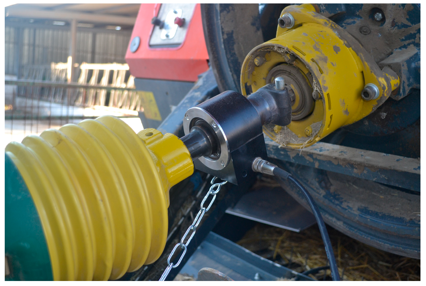
The torque value required by the PTO and its angular speed during the straw wrapping and baling process, have been measured through the contactless rotary torque transducer Datum Electronics PTO series 420 [38,39]. This transducer can measure torque strain in the shaft through an on-shaft microprocessor circuit, which also assesses the shaft rotational speed. These data are then transmitted to the stationary part via a contactless method and transmitted to the control unit [40,41]. The control unit has in turn an RS232 data connection to be linked to a laptop. A custom software allows to display and logging the measured data. Other technical features are: non-linearity +/-0.1% FSD; non-repeatability +/-0.05% FSD; sample rate from 1 to 100 samples s-1; output baud rate, 9600 baud; torque rating up to a maximum of 1,800 Nm, operating range -35 to -75°C. Figure 3 shows the rotary torque transducer Datum Electronics PTO series 420 which has been linked between the tractor PTO and the Hooke’s joint. A Datum Electronics PTO 420 series non-contact torque transducer was used to measure both the torque required by the PTO and its angular velocity during the straw wrapping and baling process [38,39]. This transducer uses a microprocessor circuit placed on the shaft to measure the deformation of its torque and rotational speed. Then, the data is sent non-contactly to the stationary part and to the control unit, which is equipped with an RS232 connector enabling connection to a laptop [40,41]. Dedicated software allows you to display and collect measurement results. Other technical features include: non-linearity +/-0.1% FSD; uniqueness +/-0.05% FSD; sampling frequency 1-100 samples per second; output baud 9600; maximum torque 1800 Nm. Figure 3 shows the Datum Electronics PTO 420 Series rotary torque converter located between the tractor's power take-off and the Hooke joint.

2.3. Hybrid Electric Agricultural Tractor Powertrain

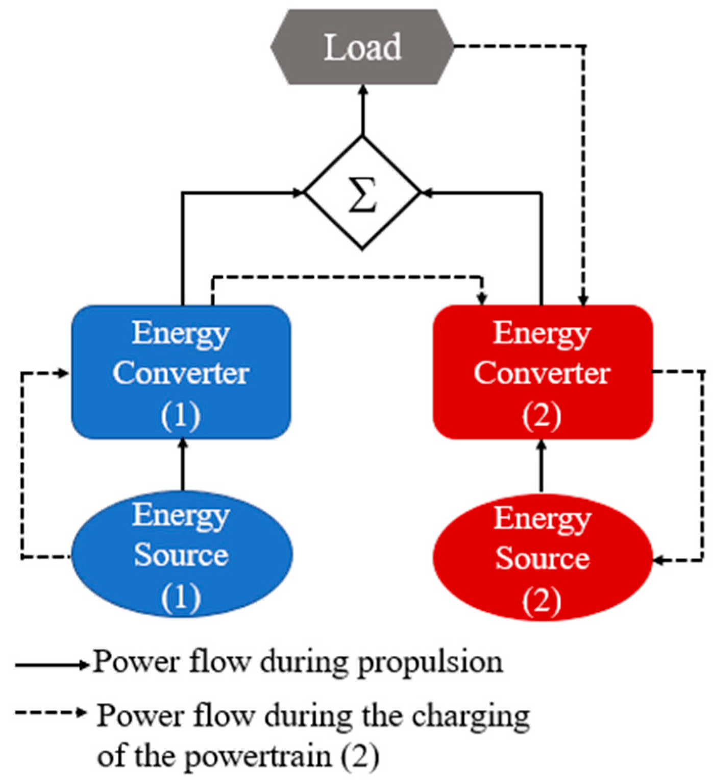
An agricultural tractor which is equipped with two different engines, one of which is an electric motor, is defined as hybrid electric. Usually, this powertrain configuration has one bidirectional and one bidirectional or unidirectional propulsion system, as presented in Figure 4. In this way it is possible to recover part of the braking energy which, in vehicles equipped with a conventional ICE, is usually dissipated in the form of heat [42,43,44]. Due to the way the two motors are connected, a distinction can be made between series and parallel electric hybrid systems.
In hybrid vehicles, the load power requirement (resistive power) is met by appropriately balancing the powers generated (driving power) by the two engines, resulting in various operational configurations [45]:
(1) The resistive power is solely satisfied by powertrain 1 or exclusively by powertrain 2 or simultaneously from both; (2) Powertrain 2 acquires power from the load, thus executing regenerative braking; (3) Powertrain 2 receives power from powertrain 1; (4) Powertrain 2 simultaneously receives power from powertrain 1 and the load; (5) Powertrain 1 concurrently supplies power to the load and powertrain 2; (6) Powertrain 1 provides power to powertrain 2, and the latter furnishes power to the load; (7) Powertrain 1 supplies power to the load, and the load, in turn, provides power to powertrain 2.
These several operating configurations are managed by programmed electronic control units which, operating each powertrain in the corresponding optimal performance region, allow to optimize their performance and efficiency.

2.4. Simulink Models for parameters calculation

2.4.1. Fuel Consumption Calculation

The Simulink model of the ICE is composed of four fundamental blocks: Engine Torque Calculation, Engine Thermal Calculation, Engine Fuel Consumption Calculation and Engine Emissions. Focusing the attention on the subsystem Engine Fuel Consumption Calculation, shown in Figure 5, it calculates the fuel consumption through a finite state machine, whose state depends on the fuel rate map of the engine and on the state in which the ICE is present.
If the ICE is started and the torque produced (Teng) is greater than the torque boundary of the fuel rate map (Tmin map), i.e. Teng > Tmin map, the instantaneous fuel consumption is a function of the engine power and the produced torque, and it depends on the fuel rate map of the engine [46]. If the ICE is started and Teng < Tmin map, since no data are available in this region, the fuel consumption must be interpolated. When Teng = Tmin map, the fuel rate at Tmin map is requested. The total mass of fuel used by the ICE during the defined working cycle is given by the formula (1).
Fuel consumption tot= ∫ Instantaneous fuel rate dt
Starting from the fuel consumption and evaluating the performances of the ICE, i.e., its state and rotational speed, during the whole working cycle, the “Autonomie” software calculates the CO2 emissions.

2.4.2. Battery State of Charge Calculation

The Simulink model of the plant of high-power batteries, employed as battery pack in the simulated series and parallel electric hybrid configurations, is reported in Figure 6. It is composed of three main blocks: Voltage Calculation, Current calculation, and the State of Charge (SOC) Calculation. Focusing the attention on the SOC calculation block, Figure 6 shows its subsystem [47]. The SOC is calculated by determining the variation of charge in the battery and dividing by the maximum capacity of the battery. The values of 0 and 1 are unattainable state because they would represent the complete discharge and charge of the battery, resulting in a short life cycle. In all the simulated configurations of the agricultural tractor, the initial SOC of the battery has been set to 70%.
From Figure 6, the SOC is given by formula (2), where SOCinit is the initial value of the SOC imposed, which is represented, in Figure 6, by the initial value of the integrator.
SOC = SOCinit + ∆SOC,
The ∆SOC is calculated as using formula (3), where Iin is the input current flowing in the battery from the bus and Cmax is the maximum charge capacity.
∆SOC = - ∫ Iin / Cmax,

3. Results

3.1. Measuring the Torque and the PTO angular speed

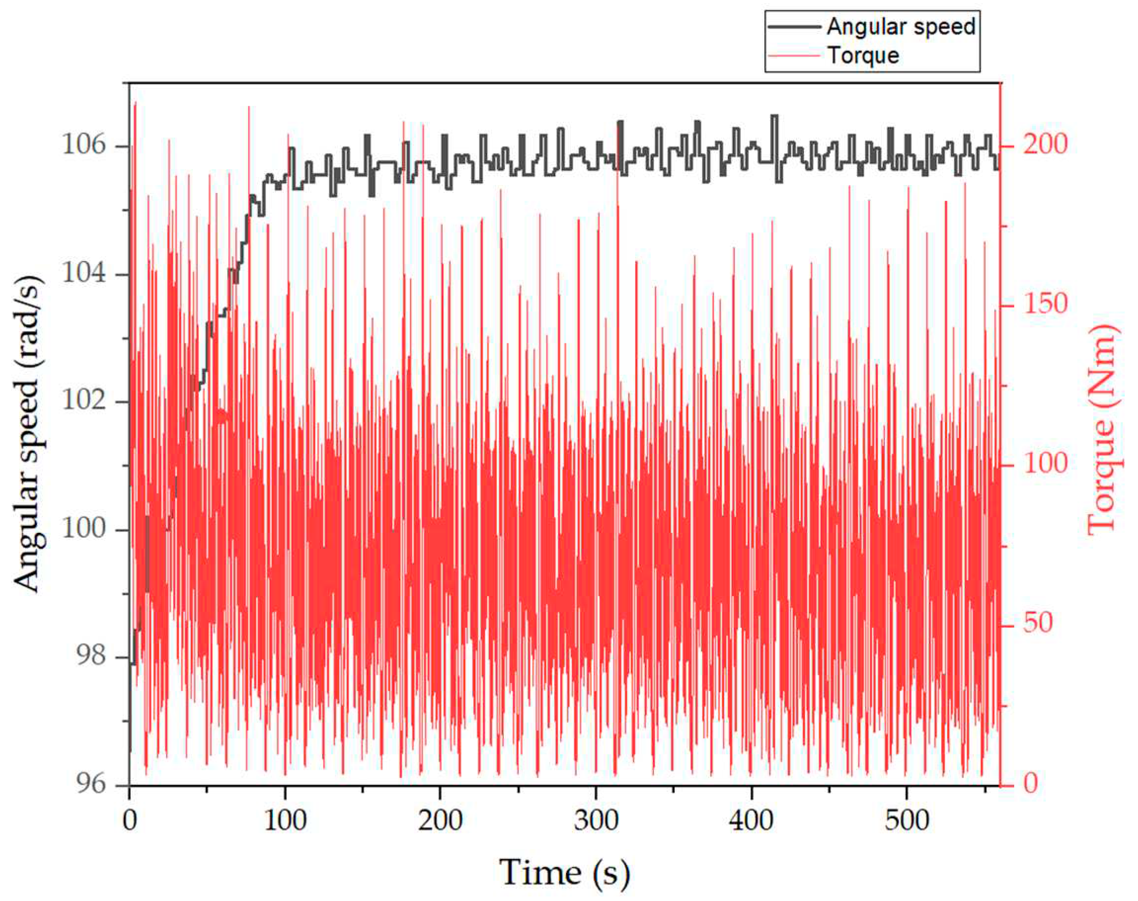
The Datum Electronics PTO 420-series non-contact rotary torque records data with an interval of 180 to 600 seconds, depending on the distance traveled by the agricultural tractor. Of the acquired data sets, one was arbitrarily selected for the analysis because the data sets did not show much diversity. Figure 7 shows the time function of the torque profile and PTO angular velocity. In turn, Table 1 collects the basic descriptive statistics of torque and PTO angular velocity: minimum and maximum values, mean values and standard deviations.
Considering the mean PTO angular speed and torque (Tmean), it is possible to calculate the mean power (Pmean) required by the large square baler Cicoria HD 1270T during straw wrapping and baling process, it is given by formula (4).
Pmean baler = Tmean * PTOmean speed ~ 7.2 kW

3.2. Parameters of the models

In this paper, three two-wheel drive agricultural tractors with different size (small, medium, large) have been modelled and simulated. Table 2 summarizes the main models’ parameters. All the tractors have a direct injection diesel engine with a 5-speed automatic transmission. The engine efficiency has been set to 40%, which is a standard value for a modern midsize diesel engine.
The friction force due to the air flow has been considered negligible due to the low speed at which the agricultural operation is taking place.
For Tractor 1 (60 kW), Tractor 2 (90 kW) and Tractor 3 (160 kW), several series and parallel electric hybrid configurations have been modelled and simulated in “Autonomie” software. For the series powertrain, the different configurations have been obtained varying the combination of the ICE-generator-electric motor powertrain specifications, i.e., their power and size. Regarding the parallel powertrain, these have been found varying the ICE and the electric motor power. The chosen configurations are those which satisfy the requirement of the target speed profile imposed by the working cycle.
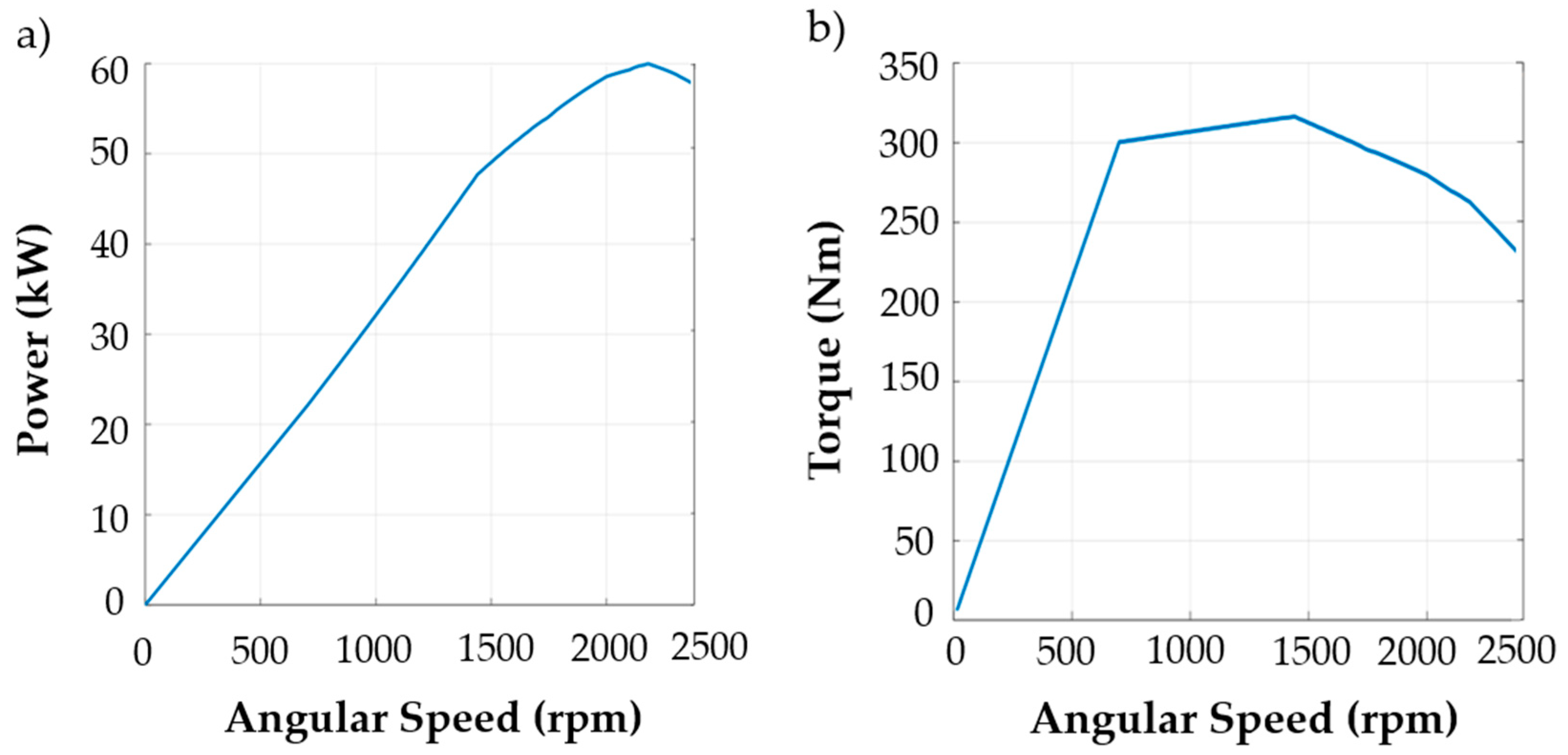
Figure 8 show the power (panel a) and the torque (panel b) profile as function of the engine rotational speed, respectively for an agricultural tractor powered by an ICE with maximum power of 60 kW at 2200 rpm and maximum torque of 315 Nm at 1400 rpm.

3.3. Models’ Simulations

3.3.1. Conventional Agricultural Tractor

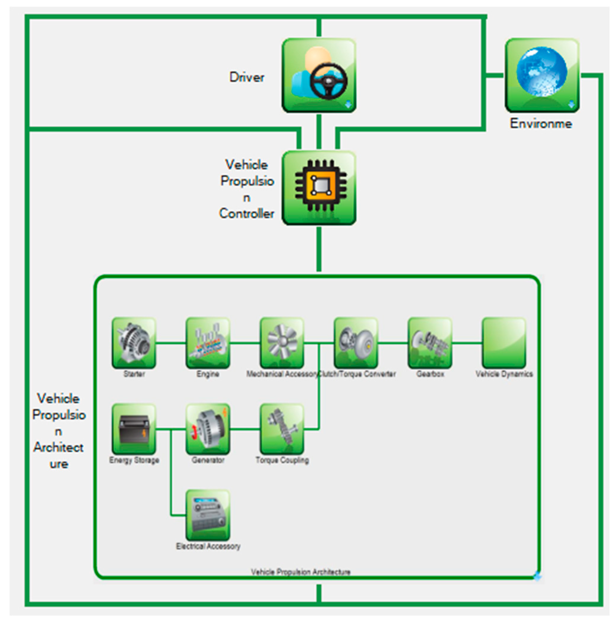
Figure 9 shows the model of a conventional agricultural tractor developed in the “Autonomie” software. The following basic blocks were used in the vehicle model: the driver, the environment model, the Vehicle Powertrain Controller (VPC), which is the high-level controller, and the Vehicle Powertrain Architecture (VPA). Due to the complexity of the powertrains, the architecture has its own system and subsystems tied to its own buses. At the most fundamental layer of abstraction, all models share an identical structure consisting of two automatically created blocks that allow the selection of inputs and the definition of units and data types, as well as a configurable block that is equivalent to a system installation. To adapt the predefined “Autonomie” vehicles’ models, to that of an agricultural tractor, several changes in different blocks of the model have been made. First of all, the Engine block has been modified, introducing a diesel engine with the parameters reported in Table 2, but also the Gearbox block and the Vehicle Dynamics block have been modified to adapt the model to the specifications defined in Table 2. Moreover, the big square baler HD 1270, which is the implement connected to the PTO is represented by the block “Mechanical Accessory”.
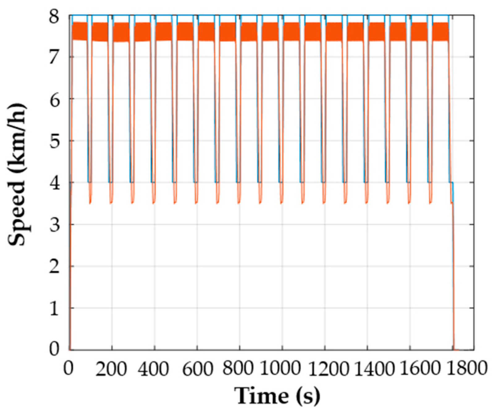
Figure 10 shows in blue the desired speed profile imposed by the defined working cycle and in orange the speed profile obtained from the model simulation of the conventional agricultural Tractor 3 (160 kW).
Table 3 summarizes the CO2 emissions in kg/h and the fuel consumption in L/h of the three simulated conventional agricultural tractors.

3.3.2. Series Electric Hybrid Agricultural Tractor

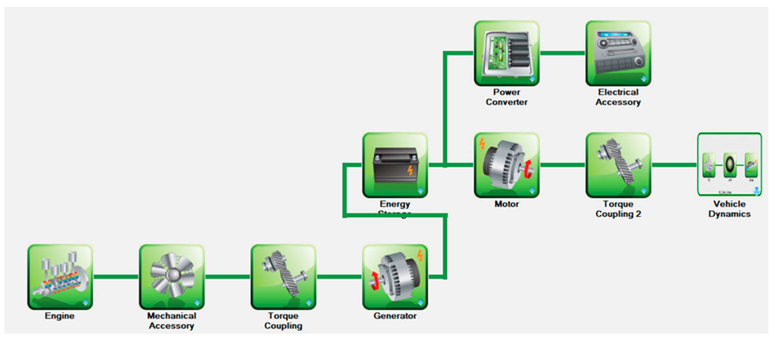
The model of a series electric hybrid agricultural tractor, developed in “Autonomie” software, is presented in Figure 11. In the series electric hybrid configuration, an electric generator is coupled with the ICE, resulting in a diesel generator set (GENSET). In this way, the ICE is used only to make up for the energy shortage of the batteries. This is a technology in which ICE is used only to replenish the energy deficiency in the batteries. The inefficiency of electric machines causes large energy losses, and this is due to the fact that in this technology, the power available for traction, PTO and auxiliary devices comes entirely from the process of double energy conversion: in the generator - from mechanical energy into electrical energy, and then in the traction motor - again from electrical energy to mechanical energy. In this configuration, the ICE engine is completely decoupled from the wheels, so it only operates on the brake-specific fuel consumption BSFC basis, which results in fuel savings. The main disadvantage of series architecture is the use of two electrical machines: a functional generator and a traction motor, which makes the vehicle heavier, larger and more expensive. The introduction of ESS as a storage of large amounts of electricity ensures appropriate energy autonomy, equalization of energy peaks, reduction of the size of the ICE and faster activation of energy reserves.
For the series electric hybrid powertrains, for each tractor two different combinations of ICE-generator-electric motor have been simulated and analyzed. The chosen powertrain configurations respect the speed profile imposed by the working cycle.
  • Tractor 1 (60 kW)
Config. A - ICE 50 kW, generator 5 kW and electric motor 5 kW;
Config. B - ICE 45 kW, generator 5 kW and electric motor 10 kW.
  • Tractor 2 (90 kW)
Config. A - ICE 70 kW, generator 10 kW and electric motor 10 kW;
Config. B - ICE 60 kW, generator 10 kW and electric motor 20 kW.
  • Tractor 3 (160 kW)
Config. A - ICE 110 kW, generator 15 kW and electric motor 35 kW;
Config. B - ICE 100 kW, generator 15 kW and electric motor 45 kW.
Table 4 reports the CO2 emissions in kg/h, the fuel consumption in L/h, and the depth of discharge of the battery pack of the simulated series electric hybrid agricultural tractor, reminding that the initial SOC has been set to 70%.

3.3.3. Parallel Electric Hybrid Agricultural Tractor

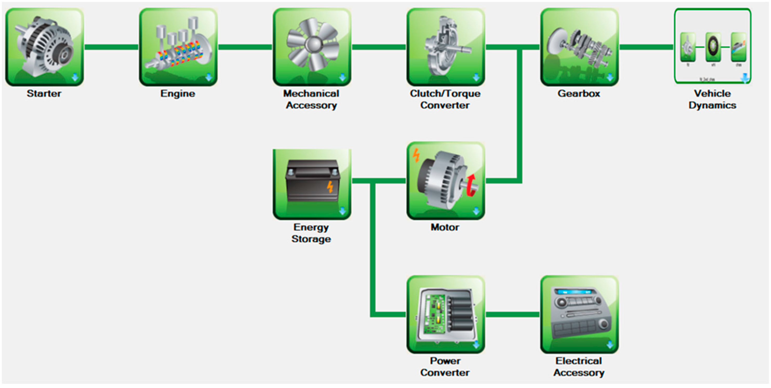
Figure 12 shows the model of a parallel electric hybrid agricultural tractor developed in the “Autonomie” software, where the electric motor is mechanically coupled with the ICE and the final drive through the gearbox. A clutch is placed between the ICE and the electric motor to decouple the two motors, allowing the tractor to operate in fully electric mode. This architecture ensures that the power from the ICE can be transferred mechanically to the wheels, as in a conventional agricultural tractor, and the electric motor is used overall to support the ICE. During low power operations the ICE can be used as a generator to recharge the ESS. This architecture is most common in hybrid vehicles because it requires the addition of one electric machine, reducing the size of the ICE without having to completely change the design.
For the parallel electric hybrid powertrains, for each tractor two different combinations of ICE-electric motor have been simulated and analyzed. The chosen powertrain configurations respect the speed profile imposed by the working cycle.
  • Tractor 1 (60 kW)
Config. A - ICE 50 kW and electric motor 10 kW;
Config. B - ICE 45 kW and electric motor 15 kW.
  • Tractor 2 (90 kW)
Config. A - ICE 80 kW and electric motor 10 kW;
Config. B - ICE 75 kW and electric motor 15 kW.
  • Tractor 3 (160 kW)
Config. A - ICE 140 kW and electric motor 20 kW;
Config. B - CE 110 kW and electric motor 50 kW.
Table 5 summarizes the CO2 emissions in kg/h, the fuel consumption in L/h, and the depth of discharge of the battery pack of the simulated parallel electric hybrid agricultural tractor.

4. Discussion

4.1. Conventional powertrain

For the conventional agricultural tractor, Table 3 reports the CO2 emissions generated by the vehicle and fuel consumption for the three simulated tractors, i.e., Tractor 1 (60 kW), Tractor 2 (90 kW), and Tractor 3 (160 kW). From Table 3 it is possible to highlight that the fuel consumption is similar for the three considered configurations, and it is equal to 5 L/h, 4.7 L/h and 5.8 L/h, respectively. It mainly depends on the operating conditions of the ICE and not strictly on the power of the tractor. Since the fuel consumptions are comparable for the three tractors, also the CO2 emissions are similar and stand at about 13 kg/h, 11 kg/h and 11.8 kg/h, respectively.

4.2. Series Electric Hybrid Powertrain

Table 4 points out that CO2 emissions and the fuel consumption of a series electric hybrid agricultural tractor are relevantly lower than the ones generated by the conventional tractor, for instance for Tractor 1 they are ten times lower. The configurations in which the electric motor is more powerful (Config. B for each tractor), have lower CO2 emissions and the fuel consumption w.r.t the Config. A. Increasing the power of the tractor, from Tractor 1 to Tractor 3 for instance, the fuel consumption increases, as well as the CO2 emissions, as expected. The depth of discharge of the battery pack stands at 23.5% on average for Tractor 1, 25.9 % on average for Tractor 2 and 27.5% on average for Tractor 3.

4.3. Parallel Electric Hybrid

Table 5 shows the simulation results for a parallel electric hybrid agricultural tractor. It was noticed that the CO2 emissions and fuel consumption of Tractor 1 are significantly lower compared to the conventional tractor, they are five times lower. In configurations with higher power electric motors (i.e. Config. B for each tractor), lower CO2 emissions and fuel consumption were observed compared to the Config. A. When increasing tractor power, for example from Tractor 1 to Tractor 3, fuel consumption and CO2 emissions increase as expected. Moreover, the battery discharge depth is on average 4.1% for Tractor 1, 6% for Tractor 2 and 7.5% for Tractor 3.

4.4. General Evaluation

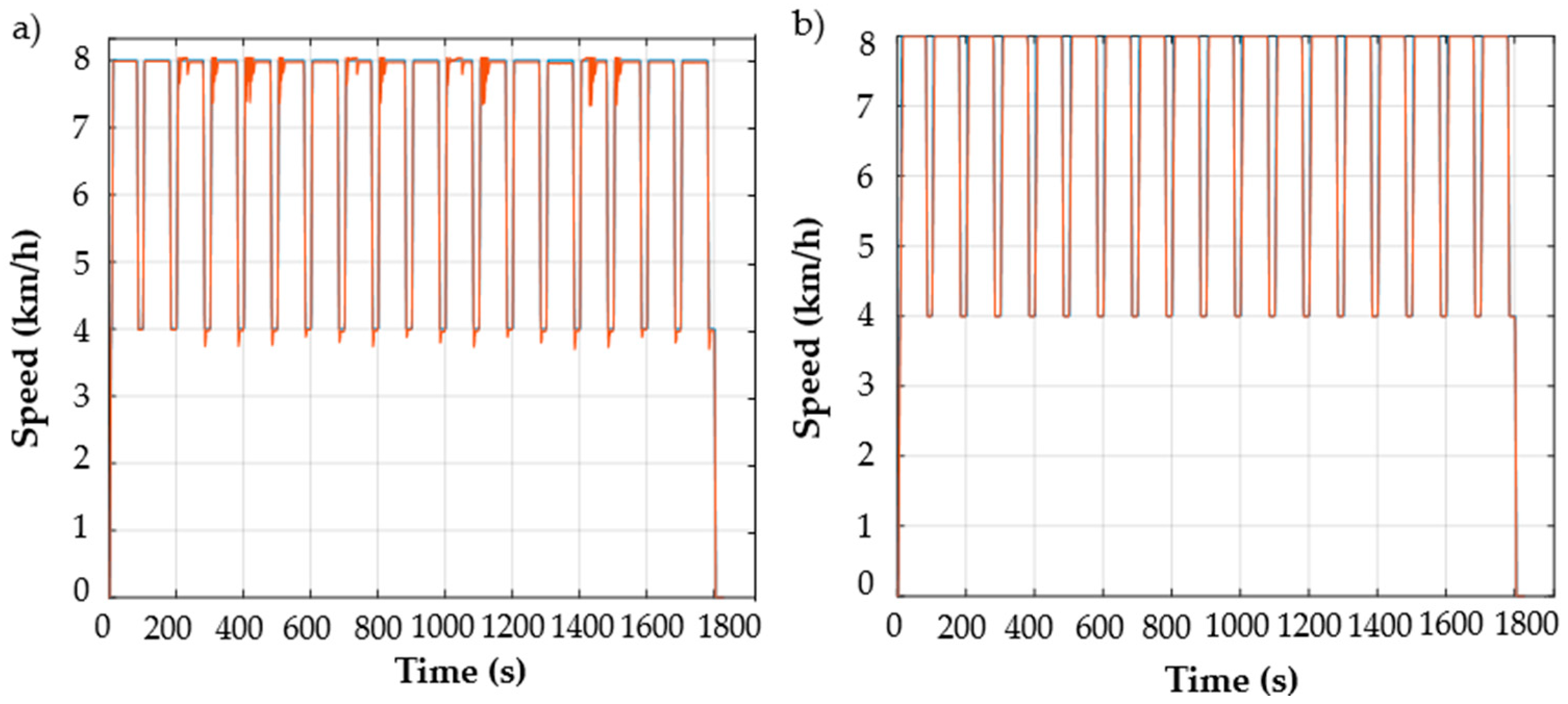
Table 4 and Table 5 highlight that it is possible to downsize the ICE of an agricultural tractor introducing one, in the case of parallel electric hybrid architecture, or two, in the case of series electric hybrid architecture, electric machines. Moreover, the electric motors allow a more flexible speed control which permits to follow the target speed profile of the working cycle in a more precise way w.r.t the conventional tractor, as shown in Figure 13. Each of these electric machines can be independently operated to consume solely the necessary power required for its operation.
From Table 4 and Table 5 it is possible to compare the CO2 emissions, the fuel consumption, and the battery pack discharge of the two electric hybrid configurations. The series electric hybrid architecture, using the electric motor as main traction powertrain and the ICE only to compensate for the energy shortage in the batteries, thus the CO2 emissions and the fuel consumption are lower than the parallel electric hybrid architecture. Furthermore, the series architecture, requiring more electric energy, has a faster discharge of the battery pack, as expected.
However, the series architecture requires two electric machines, thus this configuration is more difficult to be applied for the hybridization of existing vehicles, indeed the most employed configuration on the market is the parallel architecture.

5. Conclusions

To conclude, this paper presents the modeling and the simulation of three different sized, 60 kW (small), 90 kW (medium) and 150 kW (large) agricultural tractors during the execution of a task which simulates the trailing in the field of the big square baler HD 1270 during straw wrapping and baling process. The modelling and the simulations were performed using the “Autonomie” simulation software. The different analyzed configurations are: i) the conventional one, characterized only by the ICE; ii) the series electric hybrid, which includes the ICE and two electric machines, i.e., a generator and an electric motor; iii) the parallel electric hybrid, which is composed of the ICE and an electric motor.
The analysis and the evaluation of the performances of the task execution, the CO2 emissions and the fuel consumption of the different configurations has been carried out. A detailed study, regarding the electric hybrid configurations, has been carried out to also compare the depth of discharge of the battery pack. Moreover, a comparison between two different configurations of the hybrid powertrain, varying the power specification of the electric machines for the series and the parallel architecture, has been performed to investigate if it is possible to downsize the ICE maintaining the same performances during the execution of the task. This study highlights that the hybridization of agricultural tractors powertrains is a sustainable approach to reduce the pollutant emissions and the fuel consumption. The simulation results show clearly that hybridization cuts down the environmental impact connected to the employment of agricultural tractors and others farming machines in agricultural operations. Hybridization represents one of the most impacting technologies for the development of greener and more sustainable farming machines.

Author Contributions

Conceptualization, F.P. and S.P.; methodology, F.P. and K.L.W; formal analysis, F.P. and K.G.; investigation F.P, K.L.W, K.G, S.P.; data curation, F.P. and K.G.; writing—original draft preparation, F.P. and S.P.; writing—review and editing, F.P., K.L.W., K.G., S.P.; supervision, F.P and S.P. All authors have read and agreed to the published version of the manuscript”.

Funding

This research received no external funding.

Institutional Review Board Statement

Not applicable.

Informed Consent Statement

Not applicable.

Conflicts of Interest

The authors declare no conflicts of interest.

References

  1. Lovarelli, D.; Bacenetti, J. Exhaust gases emissions from agricultural tractors: State of the art and future perspectives for machinery operators. Biosystems Engineering 2019, 186, 204–213. [Google Scholar] [CrossRef]
  2. Gołasa, P.; Wysokiński, M.; Bieńkowska-Gołasa, W.; Gradziuk, P.; Golonko, M.; Gradziuk, B.; Siedlecka, A.; Gromada, A. Sources of Greenhouse Gas Emissions in Agriculture, with Particular Emphasis on Emissions from Energy Used. Energies 2021, 14, 3784. [Google Scholar] [CrossRef]
  3. Murawska, A.; Goryńska-Goldmann, E. Greenhouse Gas Emissions in the Agricultural and Industrial Sectors—Change Trends, Economic Conditions, and CountryD Classification: Evidence from the European Union. Agriculture 2023, 13, 1354. [Google Scholar] [CrossRef]
  4. Pérez-Martínez, PJ. Energy consumption and emissions from the road transport in Spain: a conceptual approach. Transport 2012, 27, 383–396. [Google Scholar] [CrossRef]
  5. Renius, K. T. Fundamentals of tractor design; Springer: Cham, Switzerland, 2020. [Google Scholar] [CrossRef]
  6. Hoy, R.; Rohrer, R.; Liska, A.; Luck, J.; Isom, L.; Keshwani, D. (2014). Agricultural Industry Advanced Vehicle Technology: Benchmark Study for Reduction in Petroleum Use. Adam Liska Papers 2014, 19.
  7. Sendzikiene, E.; Makareviciene, V.; Kalenska, S. Exhaust emissions from the engine running on multi-component fuel. Transport 2012, 27, 111–117. [Google Scholar] [CrossRef]
  8. Labeckas, G.; Slavinskas, S. Performance and emission charakteristics of a direct injection diesel engine operating on KDV synthetic diesel fuel. Energy Convers Manage 2013, 66, 173–88. [Google Scholar] [CrossRef]
  9. Rakopoulos, D.C.; Rakopoulos, C.D.; Kakaras, E.C; Giakoumis, E.G. Effects of ethanol diesel fuel blends on the performance and exhaust emissions of heavy duty DI diesel engine. Energy Convers Manage 2008, 49, 3155–3162. [Google Scholar] [CrossRef]
  10. Tomic, M.; Savin, L.; Micic, R.; Simikić, M.; Furman, T. Effects of fossil diesel and biodiesel blends on the performances and emissions of agricultural tractor engines. Thermal Science 2013, 17. [Google Scholar] [CrossRef]
  11. Guo, X.; Wu, H.; Chen, D.; Ye Z Shen, Y.; Liu, J.; Cheng, S. Estimation and prediction of pollutant emissions from agricultural and construction diesel machinery in the Beijing-Tianjin-Hebei (BTH) region, China☆. Environ Pollut 2020, 260, 113973. [Google Scholar] [CrossRef]
  12. Lindgren, M.; Arrhenius, K.; Larsson, G.; Bäfver, L.; Arvidsson, H.; Wetterberg, C. Analysis of unregulated emissions from an off-road diesel engine during realistic work operations. Atmos Environ 2011, 45, 5394–5398. [Google Scholar] [CrossRef]
  13. Li, Y.X.; McLaughlin, N.B.; Patterson, B.S.; Burtt, S.D. Fuel efficiency and exhaust emissions for biodiesel blends in an agricultural tractor. Can Biosyst Eng 2006, 48, 15–22. [Google Scholar]
  14. Lindgren, M.; Larsson, G.; Hansson, P.A. Evaluation of factors influencing emissions from tractors and construction equipment during realistic work operations using diesel fuel and bio-fuels as substitute. Biosyst Eng 2010, 107, 123–30. [Google Scholar] [CrossRef]
  15. Algirdas Janulevičius, Antanas Juostas, Gediminas Pupinis, Tractor’s engine performance and emission characteristics in the process of ploughing, Energy Conversion and Management, Volume 75, 2013, Pages 498-508. [CrossRef]
  16. Lovarelli, D.; Fiala, M.; Larsson, G. Fuel consumption and exhaust emissions during on-field tractor activity: A possible improving strategy for the environmental load of agricultural mechanization. Computers and Electronics in Agriculture 2018, 151. [Google Scholar] [CrossRef]
  17. Janulevicius, A.; Juostas, A.; Pupinis, G. Engine performance during tractor operational period. Energy Convers Manage 2013, 68, 9–11. [Google Scholar] [CrossRef]
  18. Hansson, P.A.; Lindgren, M.; Norén, O. A comparison between different methods of calculating average engine emissions for agricultural tractors. J Agric Eng Res 2001, 80, 37–43. [Google Scholar] [CrossRef]
  19. Bulgakov, V.; Pascuzzi, S.; Adamchuk, V.; Kuvachov, V.; Nozdrovicky, L. Theoretical study of transverse offsets of wide span tractor working implements and their influence on damage to row crops. Agriculture 2019, 9, 144. [Google Scholar] [CrossRef]
  20. An, H.; Yang, W.M.; Maghbouli, A.; Li, J.; Chou, S.K.; Chua, K.J. Performance, combustion and emission characteristics of biodiesel derived from waste cooking oils. Appl Energy 2013, 112, 493–499. [Google Scholar] [CrossRef]
  21. Martini, V.; Mocera, F.; Somà, A. Numerical Investigation of a Fuel Cell-Powered Agricultural Tractor. Energies 2022, 15, 8818. [Google Scholar] [CrossRef]
  22. Mocera, F.; Martini, V.; Soma, A. Comparative Analysis of Hybrid Electric Architectures for Specialized Agricultural Tractors. Energies 2022, 15, 1944. [Google Scholar] [CrossRef]
  23. Mocera, F.; Somà, A. Analysis of a Parallel Hybrid Electric Tractor for Agricultural Applications. Energies 2020, 13, 3055. [Google Scholar] [CrossRef]
  24. Dalboni, M.; Santarelli, P.; Patroncini, P.; Soldati, A.; Concari, C.; Lusignani, D. Electrification of a Compact Agricultural Tractor: A Successful Case Study. In Proceedings of the IEEE Transportation Electrification Conference and Expo (ITEC), Detroit, MI, USA; 2019. [Google Scholar] [CrossRef]
  25. Mocera, F.; Somà, A.; Martelli, S.; Martini, V. Trends and Future Perspective of Electrification in Agricultural Tractor-Implement Applications. Energies 2023, 16, 6601. [Google Scholar] [CrossRef]
  26. Gray, N.; O'Shea, R.; Wall, D.; Smyth, B.; Lens, P.N.L; Murphy, J. Batteries, fuel cells, or engines? A probabilistic economic and environmental assessment of electricity and electrofuels for heavy goods vehicles. Advances in Applied Energy 2022, 8. [Google Scholar] [CrossRef]
  27. Scolaro, E.; Beligoj, M.; Perez Estevez, M.; Alberti, L.; Renzi, M.; Mattetti, M. Electrification of Agricultural Machinery A Review. IEEE Access 2021, 9, 164520–164541. [Google Scholar] [CrossRef]
  28. Eftekhari, A. Energy efficiency: a critically important but neglected factor in battery research. Sustainable Energy & Fuels, 2017; 1.10, 2053–2060. [Google Scholar] [CrossRef]
  29. Lajunen, A. Simulation of energy efficiency and performance of electrified powertrains in agricultural tractors. In Proceedings of the 2022 IEEE Vehicle Power and Propulsion Conference (VPPC), Merced, CA, USA; 2022. [Google Scholar] [CrossRef]
  30. Mohsen, A.; Bilge G., C. ; Digital Twin: Benefits, use cases, challenges, and opportunities. Decision Analytics Journal 2023, 6, 100165. [Google Scholar] [CrossRef]
  31. Guerrieri, A. S.; Anifantis, A.; Santoro, F.; Pascuzzi, S. Study of a Large Square Baler with Innovative Technological Systems that Optimize the Baling Effectiveness. Agriculture 2019, 9, 86. [Google Scholar] [CrossRef]
  32. Karbowski, D.; Pagerit, S. “Autonomie”, a plug-and-play software architecture. In Proceedings of the Vehicle Power and Propulsion Conference, Lille, France; 2010. [Google Scholar]
  33. Vijayagopal, R.; Rousseau, A. System Analysis of Multiple Expert Tools. SAE Technical Paper-01-0754 2011,1-11. [CrossRef]
  34. Halbach, S.; Sharer, P.; Pagerit, S.; Rousseau, A.; et al. Model Architecture, Methods, and Interfaces for Efficient Math-Based Design and Simulation of Automotive Control Systems. SAE Technical Paper 2010. [Google Scholar] [CrossRef]
  35. Lajunen, A.; Lipman, T. Lifecycle cost assessment and carbon dioxide emissions of diesel, natural gas, hybrid electric, fuel cell hybrid and electric transit buses. Energy, 2016; 106, 329–342. [Google Scholar] [CrossRef]
  36. Rahman, S.M.A.; Fattah, I.M.R.; Ong, H.C.; Ashik, F.R.; Hassan, M.M.; Murshed, M.T.; Imran, M.A.; Rahman, M.H.; Rahman, M.A.; Hasan, M.A.M.; et al. State-of-the-Art of Establishing Test Procedures for Real Driving Gaseous Emissions from Light- and Heavy-Duty Vehicles. Energies 2021, 14, 4195. [Google Scholar] [CrossRef]
  37. Bulgakov, V.; Pascuzzi, S.; Beloev, H.; Ivanovs, S. Theoretical investigations of the headland turning agility of a trailed asymmetric implement-and-tractor aggregate. Agriculture 2019, 9, 224. [Google Scholar] [CrossRef]
  38. Crolla, D.A. Torsional Vibration Analysis of tractor and machine PTO drivelines. J. Agric. Eng. Res. 1978, 23, 259–272. [Google Scholar] [CrossRef]
  39. Crolla, D.A. Theoretical analysis of inertia torque overloads when starting up PTO driven machinery. J. Agric. Eng. Res. 1977, 22, 197. [Google Scholar] [CrossRef]
  40. Park, Y.J.; Kim, S.C.; Kim, J.G. Analysis and verification of power transmission characteristics of the hydromechanical transmission for agricultural tractors. J. Mech Sci Technol 2016, 30, 5063–5072. [Google Scholar] [CrossRef]
  41. Gomez, K.A.; Gomez, A.A. Statistical Procedures for Agricultural Research, 2nd ed.; Wiley-Interscience: New York, NY, USA, 1984. [Google Scholar]
  42. Karner, J.; Baldinger, M.; Reichl, B. Prospects of Hybrid Systems on Agricultural Machinery. GSTF Journal on Agricultural Engineering 2014, 1. [Google Scholar] [CrossRef] [PubMed]
  43. Lovarelli, D.; Fiala, M.; Larsson, G. Fuel consumption and exhaust emissions during on-field tractor activity: A possible improving strategy for the environmental load of agricultural mechanisation. Computers and Electronics in Agriculture 2018, 151, 238–248. [Google Scholar] [CrossRef]
  44. Kim, S. C.; Kim, K. U.; Kim, D. C. Prediction of fuel consumption of agricultural tractors. Applied Engineering in Agriculture 2011, 27, 705–709. [Google Scholar] [CrossRef]
  45. Khatawkkar, D.; Shaji, P.; Dhalin, D. Modern trends in farm machinery-electric drives: A review. Int.J.Curr.Microbiol.App.Sci 2019, 8, 83–98. [Google Scholar] [CrossRef]
  46. Kolator, B.A. Modeling of Tractor Fuel Consumption. Energies 2021, 14, 2300. [Google Scholar] [CrossRef]
  47. Piller, S.; Perrin, M.; Jossen, A. Methods for state-of-charge determination and their applications. Journal of power sources 2001, 96, 113–120. [Google Scholar] [CrossRef]
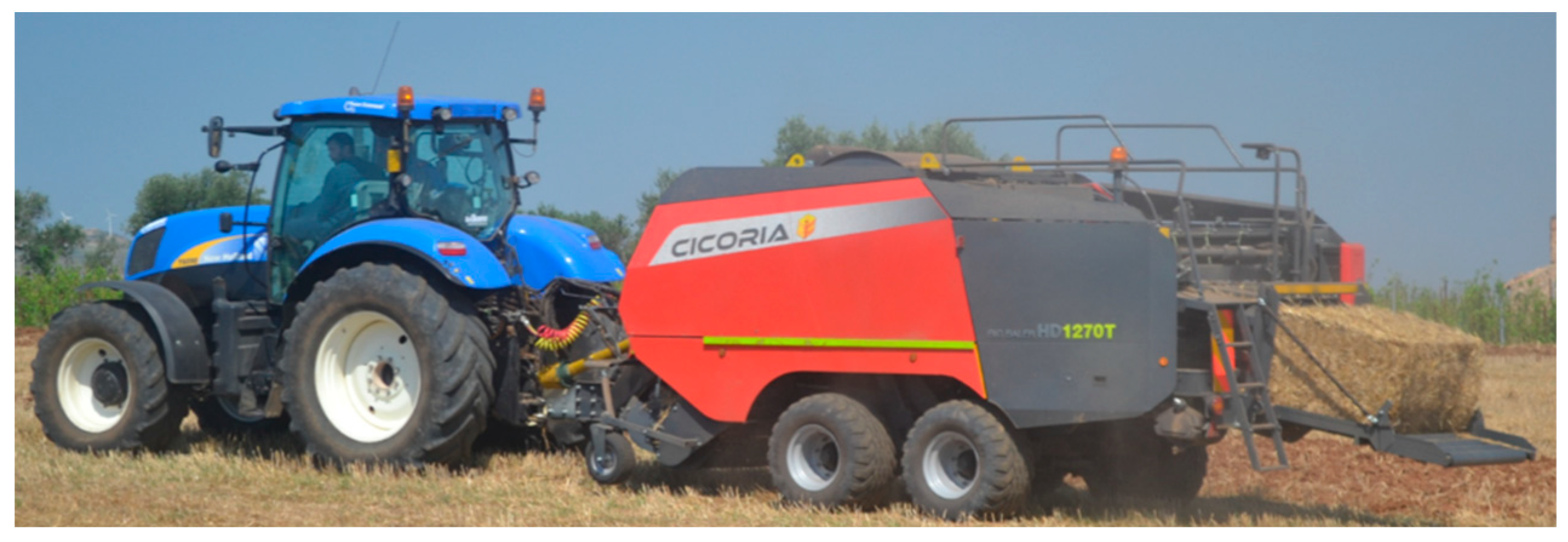
Figure 1. Big square baler Cicoria HD 1270T trailed by tractor New Holland 6090 during the tests.
Preprints 95361 g001
Figure 2. Custom defined working cycle which simulates the trailing of the Big square baler Cicoria HD 1270T. Source: Screenshot from “Autonomie” software.
Preprints 95361 g002
Figure 3. Contactless rotary torque transducer Datum Electronics PTO series 420 linked to the tractor PTO.
Preprints 95361 g003
Figure 4. Hybrid Electric Agricultural Tractor Powertrain Configuration.
Preprints 95361 g004
Figure 5. Simulink block for the fuel consumption calculation. Source: Screenshot from “Autonomie” software.
Preprints 95361 g005
Figure 6. Simulink block for the SOC of the battery calculation. Source: Screenshot from “Autonomie” software.
Preprints 95361 g006
Figure 7. Time function of the torque profile and PTO angular velocity.
Preprints 95361 g007
Figure 8. (a) ICE power profile vs engine speed (b) ICE torque profile vs engine speed for an agricultural tractor powered by an ICE with maximum power of 60 kW at 2200 rpm and maximum torque of 315 Nm at 1400 rpm.
Preprints 95361 g008
Figure 9. Model of a conventional agricultural tractor. Source: Screenshot from “Autonomie” software.
Preprints 95361 g009
Figure 10. Speed profile imposed by the working cycle (orange) and speed profile followed by the model simulation of Tractor 3 (150 kW). Source: Screenshot from “Autonomie” software.
Preprints 95361 g010
Figure 11. Model of a Series Electric Hybrid agricultural tractor. Source: Screenshot from “Autonomie” software.
Preprints 95361 g011
Figure 12. Model of a Parallel Electric Hybrid agricultural tractor. Source: Screenshot from “Autonomie” software.
Preprints 95361 g012
Figure 13. Speed profile imposed by the working cycle (orange) and speed profile followed by the model simulation of Tractor 3 (150 kW) in (a) parallel electric hybrid configuration (b) series electric hybrid configuration. Source: Screenshot from “Autonomie” software.
Preprints 95361 g013
Table 1. Basic descriptive statistics of torque and PTO angular velocity.
   Min Max  Average Standard Deviation
PTO (rad/s)  96.55 106.50 105.21 1.63
Torque (Nm)  2.64 214.41 69.25 40.94
Table 2. Main parameters of the models.
Parameter Tractor 1 Tractor 2 Tractor 3
ICE Maximum Power
@ 2200 rpm [kW]
60 kW 90 kW 160 kW
Maximum Torque
@ 1400 rpm [Nm]
315 475 845
Mass [kg] 2050 5000 8000
Wheel Radius [m] 0.3 0.38 0.42
Table 3. CO2 emissions in kg/h and the fuel consumption in L/h of the three simulated conventional agricultural tractors.
Parameter Conventional Tractor
Tractor 1 (60 kW) Tractor 2 (90 kW) Tractor 3 (160 kW)
CO2 Emission [kg/h] 13 11 11.8
Fuel consumption [L/h] 5 4.7 5.8
Table 4. CO2 emissions in kg/h, fuel consumption in L/h and depth of discharge of the simulated series electric hybrid agricultural tractor.
Parameter Series Electric Hybrid Tractor
Tractor 1 (60 kW)
Config. A  Config. B
Tractor 2 (90 kW)
Config. A  Config. B
Tractor 3 (160 kW)
Config. A  Config. B
CO2 emission [kg/h] 1.1     0.7   3     2.5    4.6      3.7
Fuel Consumption [L/h] 0.5     0.4    1.4      1.2    2.2      1.8
Δ SOC [%] -22.5    -24.5  -25.1     -26.6  -27.1     -27.7
Table 5. CO2 emissions in kg/h, fuel consumption in L/h and depth of discharge of the simulated parallel electric hybrid agricultural tractor.
Parameter Parallel Electric Hybrid Tractor
Tractor 1 (60 kW)
Config. A  Config. B
Tractor 2 (90 kW)
Config. A  Config. B
Tractor 3 (160 kW)
Config. A  Config. B
CO2 emission [kg/h] 2.3     1.6    4.5       4.2    7.7       6.3
Fuel Consumption [L/h] 1.1     0.8    2.1       2    3.5       3
Δ SOC [%] -3.3        -5    -5.5     -6.4    -7       -7.9
Disclaimer/Publisher’s Note: The statements, opinions and data contained in all publications are solely those of the individual author(s) and contributor(s) and not of MDPI and/or the editor(s). MDPI and/or the editor(s) disclaim responsibility for any injury to people or property resulting from any ideas, methods, instructions or products referred to in the content.
Copyright: This open access article is published under a Creative Commons CC BY 4.0 license, which permit the free download, distribution, and reuse, provided that the author and preprint are cited in any reuse.
Prerpints.org logo

Preprints.org is a free preprint server supported by MDPI in Basel, Switzerland.

Subscribe

© 2024 MDPI (Basel, Switzerland) unless otherwise stated