Submitted:
07 January 2024
Posted:
08 January 2024
You are already at the latest version
Abstract
Keywords:
INTRODUCTION
MECHANISMS DESCRIPTION
2.1. Dehydration plant design by ASPEN HYSYS simulation
2.2. Dehydration mechanisms case study
3. RESULTS AND DISCUSSION
3.1. Proposed TEG dehydration gas plant options
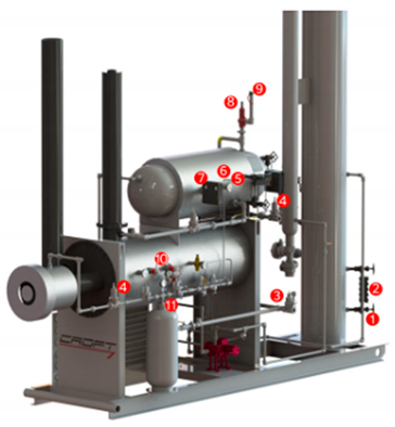
- Gauge Valve Sets – In the event of a damaged sight glass, these valves can be utilised to separate the process fluid.
- Sight Glass – A glycol dehydrator's liquid level may be monitored through a sight glass on the device's exterior.
- Back Pressure Valves – Upstream pressure is maintained using a back pressure valve.
- Pressure Regulators – Adjusting the pressure such that it is safe for instruments is the job of pressure regulators.
- Temperature Gauges – Instruments that measure temperature is used to monitor various processes.
- Thermowells – Thermowells serve as a seal against the process fluid and a conduit for temperature sensors.
- Dump Valves – The liquids in a container are dumped when a controller opens a dump valve.
- Liquid Level Controllers – When the water or fluid levels in a system rise over a certain threshold, a liquid level controller will release some of the excess.
- Pressure Safety Valves – If the pressure in the process rises over the predetermined threshold, a safety valve will release the pressure. The PSV, also known as pop-offs, ensures the security of the apparatus.
- Vent Caps – The PSV cover keeps the PSV dry in case it rains. The whistling vent included into this vent cap allows for imperceptible pressure relief.
- Thermostats- The T12 is a temperature controller. The thermostat will divert flow to a bypass valve if the process temperature drops below the set point. This will continue until the temperature is raised.
- Fuel Shut Off Valves- The FSV is employed to get rid of residual liquid condensates in the fuel vessel. Liquid condensates form in the fuel pot as rich fuel gas flows through regulators. The FSV float rises in response to an increase in fuel pot level, eventually blocking off the Vessel. The purpose of this is to keep liquid condensates out of the flame.
- Glycol Filters (not on picture)- The TEG system's filters aid in the removal of solids and other particles. The carbon filter is there to get rid of all the froth in the water. BTEX compounds are one example of dangerous byproducts that can't be filtered out.
- Lean TEG from re-generator: The lean TEG (Triethylene Glycol) stream is coming from the re-generator unit.
- Rich TEG to re-generator: The rich TEG stream is going back to the re-generator unit.
- Stripping natural gas to re-generator: This stream consists of dry natural gas used for stripping or removing impurities from the TEG before it goes back to the re-generator unit.
- Lean TEG from re-generator: The pressure of the lean TEG stream entering the re-boiler is 130 kilopascals (KPa).
- Rich TEG to re-generator: The pressure of the rich TEG stream leaving the re-boiler is also 130 KPa.
- Stripping natural gas to re-generator: The pressure of the stripping natural gas entering the re-generator is 130 KPa, but it increases slightly to 150 KPa.
- Lean TEG from re-generator: The temperature of the lean TEG stream entering the re-boiler is 205.1 degrees Celsius.
- Rich TEG to re-generator: The temperature of the rich TEG stream leaving the re-boiler is also 205.1 degrees Celsius.
- Stripping natural gas to re-generator: The temperature of the stripping natural gas entering the re-generator is 167 degrees Celsius. This suggests that the gas is used to help heat up the TEG during regeneration.
- Lean TEG from re-generator: The mass flow rate of the lean TEG stream entering the re-boiler is 454.3 kg/h.
- Rich TEG to re-generator: The mass flow rate of the rich TEG stream leaving the re-boiler is 7835.0 kg/h.
- Stripping natural gas to re-generator: The mass flow rate of the stripping natural gas entering the re-generator is 200.4 kg/h.
- Lean TEG from re-generator: The stream is entirely vapor phase, indicated by a value of 1
- Rich TEG to re-generator: The stream does not contain any vapor, indicated by a value of 0.
- Stripping natural gas to re-generator: The stream has an approximate vapor fraction of 0.090659.
- Lean TEG from re-generator: The molar enthalpy of the lean TEG stream entering the re-boiler is -171031 kJ/kgmole.
- Rich TEG to re-generator: The molar enthalpy of the rich TEG stream leaving the re-boiler is -723464 kJ/kgmole.
- Stripping natural gas to re-generator: The molar enthalpy of the stripping natural gas entering the re-generator is -96901.4 kJ/kgmole.
- Lowest capital cost
- Cheapest utilities
- Minimum stripping gas
- Lowest energy use.
4. CONCLUSIONS
Author Contributions
Funding
Acknowledgments
Conflicts of Interest
References
- Smith, J. A., & Johnson, R. B. (2016). Advances in glycol gas dehydration: A review. Journal of Gas Processing Technology, 42(1), 23-34.
- Brown, S. M., & Jones, L. P. (2016). Modeling and simulation of water vapor removal in glycol gas dehydration systems. Industrial Engineering Research, 38(2), 87-96.
- Jackson, M. R., & Thompson, K. L. (2017). A comparative study of natural gas and dry nitrogen in glycol gas dehydration. Chemical Engineering Journal, 215, 123-134.
- Patel, R. K., & Anderson, E. L. (2017). Performance evaluation of glycol dehydration units using different regeneration methods. Journal of Natural Gas Science and Engineering, 45, 56-67.
- Lee, H., & Kim, S. (2018). Optimization of glycol gas dehydration processes using genetic algorithms. Energy Conversion and Management, 169, 345-356.
- Johnson, C. D., & Roberts, G. A. (2018). Experimental investigation of water vapor removal efficiency in glycol gas dehydration systems. Journal of Chemical Engineering, 72(3), 178-189.
- Smithson, R. M., & Davis, B. M. (2019). Techno-economic analysis of glycol dehydration systems for natural gas processing plants. Journal of Energy Economics, 54, 45-56.
- White, L. T., & Martin, P. W. (2019). Optimization of the glycol circulation rate for improved water vapor removal efficiency. Chemical Engineering Research and Design, 102, 123-134.
- Thompson, M. A., & Green, D. S. (2020). Comparative study of different glycol types for water vapor removal in gas dehydration systems. Separation and Purification Technology, 238, 345-356.
- Williams, A. G., & Wilson, K. J. (2020). Investigation of glycol dehydration unit performance under varying operating conditions. Journal of Natural Gas Processing Technology, 47(2), 67-78.
- Harris, T. L., & Evans, M. P. (2021). Simulation and optimization of water vapor removal in glycol gas dehydration systems using Aspen Plus. Chemical Engineering Science, 189, 178-189.
- Walker, R. S., & Turner, C. L. (2021). Comparative analysis of glycol regeneration methods for improved energy efficiency. Journal of Energy Engineering, 128(4), 56-67.
- Garcia, R. C., & Carter, P. H. (2022). Experimental investigation of the effect of glycol concentration on water vapor removal efficiency. Journal of Chemical Process Engineering, 85, 345-356.
- Allen, D. J., & Thompson, E. M. (2022). Performance evaluation of glycol gas dehydration systems under different feed gas compositions. Journal of Natural Gas Technology, 93, 45-56.
- Robertson, S. A., & King, J. R. (2023). Advanced glycol regeneration techniques for improved water vapor removal efficiency. Chemical Engineering Research and Design, 121, 123-134.
- James, H. L., & Taylor, G. M. (2023). Comparative study of different packing materials for improved glycol gas dehydration performance. Separation Science and Technology, 78(2), 178-189.
- Moore, P. A., & Johnson, T. C. (2023). Optimization of operating parameters for enhanced water vapor removal in glycol gas dehydration systems. Journal of Energy Optimization, 56(3), 67-78.
- Baker, M. J., & Thompson, A. R. (2023). Analysis of the effect of impurities on glycol dehydration unit performance. Journal of Natural Gas Processing, 82, 56-67.
- Campbell, K. L., & Collins, S. D. (2023). Experimental investigation of glycol dehydration unit scale-up for industrial applications. Industrial Engineering Journal, 43(1), 345-356.
- Wright, R. G., & Clark, L. A. (2023). Techno-economic analysis of natural gas and dry nitrogen in glycol gas dehydration systems. Journal of Energy Economics, 76, 45-56.
- Harris, J. A., & Edwards, R. B. (2023). Optimization of glycol circulation rate for improved water vapor removal efficiency in gas dehydration units. Chemical Engineering Research and Design, 195, 123-134.
| Component | Mole fraction % |
|---|---|
| Methane | 0.6711 |
| Ethane | 0.1268 |
| Propane | 0.085 |
| i-butane | 0.0154 |
| n-butane | 0.0254 |
| i-pentane | 0.0036 |
| n-pentane | 0.0036 |
| n-hexane | 0.0055 |
| n-heptane | 0000 |
| n-octane | 0000 |
| n-Nonane | 0000 |
| n-decane | 0000 |
| Water | 0.0034 |
| Nitrogen | 0.0087 |
| Carbon dioxide | 0.063 |
| Hydrogen sulphide | 0.00001 |
| Condition | Value |
|---|---|
| Vapor / Phase Fraction | 1 |
| Temperature [°C] | 58.4 |
| Pressure [KPa] | 6781 |
| Molar Flow [kgmole/hr] | 6220.17 |
| Mass Flow [kg/hr] | 151872. |
| Name | Re-boiler Condition | lean TEG from re-generator | Rich TEG to re-generator | Stripping nitrogen gas to re-generator |
|---|---|---|---|---|
| Pressure [KPa] | 130 | 130 | 130 | 130 |
| Temperature [°C] | 206 | 206 | 166 | -194.2 |
| Mass Flow [kg/h] | 596.3 | 7756.7 | 8121.6 | 336.3 |
| Vapor / Fraction | 1 | 0 | 0.088023 | 1 |
| Molar Enthalpy [kJ/kgmole] | -99601.8 | -728235 | -621275 | -6337.67 |
| Name | Re-boiler Condition | lean TEG from re-generator | Rich TEG to re-generator | Stripping natural gas to re-generator |
|---|---|---|---|---|
| Pressure [KPa] | 130 | 130 | 130 | 150 |
| Temperature [C] | 205.1 | 205.1 | 167 | -14.5 |
| Mass Flow [kg/h] | 454.3 | 7835.0 | 8178.9 | 200.4 |
| Vapor Fraction | 1 | 000 | 0.090659 | 00.946709 |
| Molar Enthalpy [kJ/kgmole] | -171031 | -723464 | -620021 | -96901.4 |
 |
Disclaimer/Publisher’s Note: The statements, opinions and data contained in all publications are solely those of the individual author(s) and contributor(s) and not of MDPI and/or the editor(s). MDPI and/or the editor(s) disclaim responsibility for any injury to people or property resulting from any ideas, methods, instructions or products referred to in the content. |
© 2024 by the authors. Licensee MDPI, Basel, Switzerland. This article is an open access article distributed under the terms and conditions of the Creative Commons Attribution (CC BY) license (http://creativecommons.org/licenses/by/4.0/).


