Submitted:
05 January 2024
Posted:
08 January 2024
You are already at the latest version
Abstract
The thermal degradation of brakes has a significant impact on the stability of pure electric commercial vehicles during long downhill braking. Based on road slope and using fuzzy control method, design strategies for motor regenerative braking force and friction braking force distribution, with the aim of reducing friction braking force, improving braking stability, and recovering braking energy. By establishing driving conditions on roads with different slopes and using numerical analysis methods to verify the proposed control strategy. the results show that under the 6% constant slope driving condition, the vehicle maintains a constant speed of 30km/h downhill driving, and the braking energy recovery rate reaches 50.93%; Under the condition of 3% -6% gradient driving, the vehicle speed fluctuates slightly, but it can still be maintained at a constant speed of 30km/h for downhill driving through the adjustment of the motor's reverse drag characteristic, with a braking energy recovery rate of 49.97%; During the process of driving downhill at a constant speed, the frictional braking force does not participate in braking; The braking energy recovery rate is determined by the slope and braking deceleration.
Keywords:
electric commercial vehicle
; slope driving conditions
; long downhill braking
; brake energy recovery
; fuzzy control
1. Introduction
Nowadays, the development trend of new energy vehicles is rapid, and pure electric commercial vehicles are receiving attention in areas such as energy conservation, environmental protection, and economy. With the continuous development of motor technology, the speed and torque that vehicle motors can provide are also constantly increasing. This enables commercial vehicles to provide continuous braking for a long time when driving on long downhill slopes, thereby reducing friction braking force, reducing brake thermal decay, and recovering braking energy, improving energy utilization efficiency [1].
The braking energy recovery rate is mainly determined by the driving conditions of the vehicle and the energy recovery control strategy. Control strategies can be formulated based on different driving conditions of the vehicle to distribute the frictional braking force of the front and rear axles and the regenerative braking force of the motor, in order to improve the braking energy recovery rate. Takuya Yabe et al. [2] based on Matlab / Simulink, the simulation model of the whole vehicle is established to clarify the influence of motor capacity and battery current on the regeneration energy. By connecting the speed difference between the vehicle and the motor, it is assumed that in the ideal condition, the lateral motion of the vehicle is not considered, and the variable transmission ratio is selected to optimize the braking energy recovery rate of the vehicle.Wei Zhang et al. [3] based on Matlab / Simulink and ADVISOR, the vehicle model is established, and the regenerative braking priority control strategy is adopted to distribute the axle load and braking force on the uphill and downhill road slope to maximize the recovery of braking energy.Zhe Li et al. [4] based on the driver's braking intention, the braking mode is determined by fuzzy theory and logical threshold method, and the braking energy is recovered by fuzzy control rules with road slope, braking intensity and speed as input parameters and braking force proportional coefficient as output parameters.The above research lacks research on the relationship between rear axle drive, continuous motor braking, and friction braking. This article proposes a braking force distribution control strategy based on rear axle drive vehicles, which divides the long downhill braking into two processes. Firstly, the vehicle is slowed down to a constant driving speed on the long downhill in the shortest possible time. Then, the main braking force is provided by the motor, and the remaining braking force is provided by the friction braking, thereby controlling the vehicle to go downhill at a constant speed.
2. Long Downhill Braking Control Strategy
This article mainly focuses on the study of continuous braking for pure electric commercial vehicles during long downhill driving, with the main braking force provided by the motor [5], and the main purpose of reducing friction braking force. The overall control strategy for long downhill braking is proposed as shown in Figure 1. The overall strategy is divided into three parts: braking force calculation, braking force distribution, and execution control.
1) Braking force calculation: Referring to the vehicle dynamics model, calculate the required braking force of the entire vehicle based on the road slope i.
2) Braking force distribution: A fuzzy controller is established by taking the braking strength z,vehicle speed v, the state of charge (SOC) of the battery as inputs, and the proportion of regenerative braking force of the motor to the required braking force of the entire vehicle k as output, and the remaining required braking force is distributed to the front and rear axles.
3) Input the regenerative braking force and friction braking force of the motor into the established model to verify the control strategy.
2.1. Vehicle Demand Braking Force
When driving downhill for a long time, the vehicle is mainly subjected to slope force, frictional resistance, air resistance, and inertial force [6]. Therefore, the required braking force for the entire vehicle is:
In the formula, Frequest is the required braking force for the entire vehicle; Fi is the slope force; Ff is the frictional resistance; Fw is the air resistance; Fj is the inertial force.
2.2. Fuzzy Controll
The continuous braking of pure electric commercial vehicles on long downhill slopes studied in this article is a non-linear relationship between the regenerative braking force provided by the motor and the frictional braking force working together. Fuzzy control is used to control nonlinear systems through existing experience and knowledge, without the need to know the specific structure and mathematical model of the controlled object [7]. Therefore, fuzzy control is considered. A fuzzy controller is established with braking strength z, vehicle speed v, and battery SOC as inputs, and the proportion of regenerative braking force of the motor to the required braking force of the entire vehicle k as output.
The fuzzy subset of braking strength z is {L, M, H}, and the domain is [0,1]; The fuzzy subset of vehicle speed v is {L, M, H}, with a domain of [0,100]; The fuzzy subset of battery SOC is {L, M, H}, with a domain of [0,1]; The fuzzy subset of the proportional coefficient k for the regenerative braking force of the motor is {LL, L, M, H, HH}, and the domain is [0,1]. The membership functions of braking strength z, vehicle speed v, battery SOC, and motor regenerative braking force ratio coefficient k are shown in Figure 2. Based on a large number of experiments and theoretical analysis, fuzzy control rules have been formulated as shown in Table 1.
2.3. Calculation of Regenerative Braking Force for Motor
The synchronous motor has four quadrant working characteristics and can function as a generator during vehicle braking. Its external characteristic curve is similar to that of the electric motor [8]. Therefore, the mathematical model of the regenerative braking force of the motor can be derived as follows:
In the formula, Fe is the regenerative braking torque provided by the motor; i0 is the transmission ratio; ηt is the transmission efficiency; r is the radius of the wheel; Pe is the rated power of the motor; n is the motor speed, and ne is the rated motor speed.
2.4. Remaining Demand Braking Force Distribution
When the vehicle brakes on a long downhill slope, the motor bears the main braking force.When the required braking force of the entire vehicle is higher than the maximum braking force that the motor can provide, the remaining required braking force is provided by the friction braking force of the front and rear axles [9].
If the required braking force of the vehicle is entirely provided by frictional braking force, and the front and rear axle wheels lock up simultaneously, the ground normal reaction force on the front and rear axles is:
At this time, the braking force of the front and rear axles of the vehicle on any long downhill road surface with any coefficient of adhesion is:
In the formula, Fz1 is the front normal reaction force; Fz2 is the rear normal reaction force; Fx1 is the front axle friction braking force; Fx2 is the rear axle friction braking force; Hg is the height of the car's center of mass; L is the distance from the front axle to the rear axle; a is the distance from the front axle to the center of mass; b is the distance from the rear axle to the center of mass; G is the vehicle's gravity; α is the slope angle of the road; φ is the coefficient of adhesion on the road surface.
According to Equations (3) and (4), draw the distribution curves of front and rear axle friction braking force as shown in Figure 3.
The braking strength of point A on the I curve is z=0.22. According to Equation (5), the coordinates of point A are (Fx1A, Fx2A), and the slope of the OA line segment is KOA=Fx2A/Fx1A. Therefore, the distribution of frictional braking force on the OA line segment is:
The braking strength of point B is z=0.53. Similarly, according to Equation (5), the coordinates of point B are (Fx1B, Fx2B), and the slope of line segment AB is KAB=(Fx2B- Fx2A)/(Fx1B-Fx1A). Therefore, the distribution of frictional braking force on line segment AB is:
Point C is located at the β line, the braking strength z=0.7 satisfies the following relationship:
In the formula, β is the distribution coefficient of friction braking force for the front and rear axles.
According to Equation (8), the coordinates of point C are (Fx1C, Fx2C), and the slope of the BC line segment is KBC=(Fx2C-Fx2B)/(Fx1C-Fx1B). Therefore, the distribution of frictional braking force on the BC line segment is:
When the braking strength z>0.7, it belongs to emergency braking and exits the braking energy recovery mode. In order to quickly and accurately distribute the braking force to the front and rear axles, it is necessary to follow the β Line allocation:
2.5. Execution Control Constraint
To prevent overcharging and discharging of the vehicle's power battery, when the battery SOC exceeds 90%, it will exit the regenerative braking mode and switch to friction braking, providing full braking force [10].When the vehicle speed is very low, the speed of the motor is also very low, and the generated charging current is very small, which is not enough to effectively charge the battery. Therefore, in order to stop the vehicle as soon as possible, when the speed is below 5km/h, exit the regenerative braking mode and switch to friction braking and provide all braking force [11].
3. Establish a Control Ctrategy Model
4. Results and Discussion
4.1. Analysis of Driving Conditions and Results of Fixed Slope and Long Downhill Driving
According to the requirements of the braking test for commercial vehicles in GB12676-2014, the initial speed of the vehicle for long downhill driving is set to 60km/h, the constant speed for long downhill driving is 30km/h, the road slope is 6%, the driving distance is 6km, and the initial SOC value of the power battery is 60% [12]. The test results are shown in Figure 5, Figure 6 and Figure 7.
From Figure 5, it can be seen that when the vehicle enters a long downhill driving cycle, the speed drops from 60km/h to 30km/h within 200 meters, and then all braking force is provided by the regenerative braking force of the motor to maintain a constant speed of 30km/h, completing a 6km long downhill driving cycle.
From Figure 6, it can be seen that during the period when the vehicle speed decreases from 60km/h to 30km/h, there is a deceleration of the vehicle, and the motor provides a larger regenerative braking torque. The battery SOC increases rapidly, and after the vehicle speed stabilizes, the motor regenerative braking torque tends to stabilize. The battery SOC basically shows a linear and stable increase, increasing from the initial 60% to 63.3%, and the overall braking energy recovery rate reaches 50.93%.
During the downhill driving process at a constant speed of 30km/h, the friction braking torque remained zero. Figure 7 shows the variation of the friction braking torque by selecting the data of the first 500m driving distance. At the beginning of the experiment, as the driver presses the brake pedal, the friction braking torque and motor regenerative braking torque rapidly increase. As the vehicle speed decreases, the driver relaxes the brake pedal, and the friction braking torque gradually decreases to zero and no longer participates in braking. At the same time, the motor bears all the braking torque.
4.2. Analysis of Driving Conditions and Results of Variable Slope and Long Downhill Driving
Select a 6km long road from the 122km to 128km section of National Highway 318 as the test road condition. The road section has a 3% slope of 1km, a 4% slope of 1km, a 5% slope of 2km, and a 6% slope of 2km, with an average slope of 4.83%. The road slope information is shown in Figure 8. Set the initial speed of the vehicle for long downhill driving to 60km/h, and the initial SOC value of the power battery to 60% [13]. The test results are shown in Figure 9, Figure 10 and Figure 11.
From Figure 9, it can be seen that when the vehicle enters a long downhill driving, the speed still drops from 60km/h to 30km/h within 200 meters. Due to the initial slope of the road section being 3%, the motor provides a small regenerative braking torque to keep the vehicle driving at a speed of 30km/h. When the road slope increases from 3% to 5%, due to the inability of the regenerative braking torque of the motor to instantaneously increase or decrease, the vehicle speed first increases and then decreases. When the road slope increases from 6% to 4%, the vehicle speed first decreases and then increases. The regenerative braking torque of the motor also increases or decreases with the change of road slope, which can keep the vehicle driving downhill at a constant speed of 30km/h.
From Figure 10, it can be seen that when the road slope changes, the regenerative braking torque provided by the motor also changes, and the growth rate of battery SOC also increases or decreases with the change of road slope. The SOC value increases from 60% to 62.35%, and the overall braking energy recovery rate reaches 49.97%.
The friction braking torque in Figure 11 and the regenerative braking force torque provided by the motor are smaller than those in Figure 7, because the slope of the road where the vehicle begins to enter is 3% and less than 6%, the slope force on the vehicle decreases, the required braking torque for the entire vehicle decreases, and the required deceleration distance also decreases accordingly. However, the overall trend of braking force change remains unchanged.
5. Conclusions
When pure electric commercial vehicles brake on long downhill slopes, the braking load rapidly increases, and the brakes are prone to thermal degradation.Based on the braking strength and the fuzzy control method, a braking force distribution strategy is designed. The following conclusions are drawn from the results of the long downhill driving condition:
1) Under the constant slope driving condition, the motor provides continuous braking, allowing the vehicle to maintain a constant speed of 30km/h downhill driving, and the braking energy recovery rate reaches 50.93%.
2) Under variable slope driving conditions, the regenerative braking torque of the motor also changes accordingly with the size of the slope: as the slope decreases, the regenerative braking torque decreases, and as the slope increases, the regenerative braking torque increases.This enables the vehicle to maintain a constant speed of 30km/h downhill driving, with a braking energy recovery rate of 49.97%.
3) When the vehicle decelerates to a constant speed of 30km/h, the frictional braking force no longer participates in braking, which can effectively prevent the brake from experiencing thermal decay and improve the vehicle's braking stability.This section may be divided by subheadings. It should provide a concise and precise description of the experimental results, their interpretation, as well as the experimental conclusions that can be drawn.
Author Contributions
Investigation, W.C. and C.L.; methodology, W.C. and C.L.; software, W.C.; resources, C.L.; writing-original draft, W.C.; writing-review and editing, W.C. and C.L.; All authors have read and agreed to the published version of the manuscript.
Funding
This research was funded by National Natural Science Foundation of China (Grant No. 11802108).
Data Availability Statement
The experimental data is contained within the article.
Acknowledgments
Not applicable.
Conflicts of Interest
Not applicable.
References
- Wager, G.; Whale, J.; Braunl, T. Performance Evaluation of Regenerative Braking Systems. Proceedings of the Institution of Mechanical Engineers, Part D: Journal of Automobile Engineering 2018, 232, 1414–1427. [Google Scholar] [CrossRef]
- Yabe, T.; Akatsu, K.; Okui, N.; Niikuni, T.; Kawai, T. Efficiency Improvement of Regenerative Energy for an EV. WEVJ 2012, 5, 494–500. [Google Scholar] [CrossRef]
- Zhang, W.; Yang, J.; Zhang, W.; Ma, F. Research on Regenerative Braking of Pure Electric Mining Dump Truck. WEVJ 2019, 10, 39. [Google Scholar] [CrossRef]
- Li, Z.; Shi, Z.; Gao, J.; Xi, J. Research on Regenerative Braking Control Strategy for Single-Pedal Pure Electric Commercial Vehicles. WEVJ 2023, 14, 229. [Google Scholar] [CrossRef]
- Trovão, J.P.; Santos, V.D.N.; Pereirinha, P.G.; Jorge, H.M.; Antunes, C.H. Comparative Study of Different Energy Management Strategies for Dual-Source Electric Vehicles. 2013, 6. 6.
- Miri, I.; Fotouhi, A.; Ewin, N. Electric Vehicle Energy Consumption Modelling and Estimation—A Case Study. Int J Energy Res 2021, 45, 501–520. [Google Scholar] [CrossRef]
- Khanra, M.; Chakraborty, D.; Nandi, A.K. Improvement of Regenerative Braking Energy of Fully Battery Electric Vehicle Through Optimal Driving. JAEV 2018, 16, 1789–1798. [Google Scholar] [CrossRef]
- Yu, Y.; Jiang, J.; Min, Z.; Wang, P.; Shen, W. Research on Energy Management Strategies of Extended-Range Electric Vehicles Based on Driving Characteristics. WEVJ 2020, 11, 54. [Google Scholar] [CrossRef]
- Krishnamoorthy, K.; Pazhamalai, P.; Mariappan, V.K.; Manoharan, S.; Kesavan, D.; Kim, S. Two-Dimensional Siloxene–Graphene Heterostructure-Based High-Performance Supercapacitor for Capturing Regenerative Braking Energy in Electric Vehicles. Adv Funct Materials 2021, 31, 2008422. [Google Scholar] [CrossRef]
- Chen, B.; Evangelou, S.A.; Lot, R. Series Hybrid Electric Vehicle Simultaneous Energy Management and Driving Speed Optimization. IEEE/ASME Trans. Mechatron. 2019, 24, 2756–2767. [Google Scholar] [CrossRef]
- Zhao Luhua; Cao Qinggui; Li Yushan; Gao Naixiu An Optimization Technique of Braking Force Distribution Coefficient for Truck. In Proceedings of the Proceedings 2011 International Conference on Transportation, Mechanical, and Electrical Engineering (TMEE); IEEE: ChangChun, China, December 2011; pp. 1784–1787.
- Goodarzi, A.; Mehrmashhadi, J.; Esmailzadeh, E. Optimised Braking Force Distribution Strategies for Straight and Curved Braking. IJHVS 2009, 16, 78. [Google Scholar] [CrossRef]
- Xu, J.; Zhang, X. Optimization Algorithm for Vehicle Braking Force Distribution of Front and Rear Axles Based on Brake Strength. In Proceedings of the 2016 12th World Congress on Intelligent Control and Automation (WCICA); IEEE: Guilin, China, June, 2016; pp. 3353–3360. [Google Scholar]
Figure 1.
Long downhill braking control strategy.
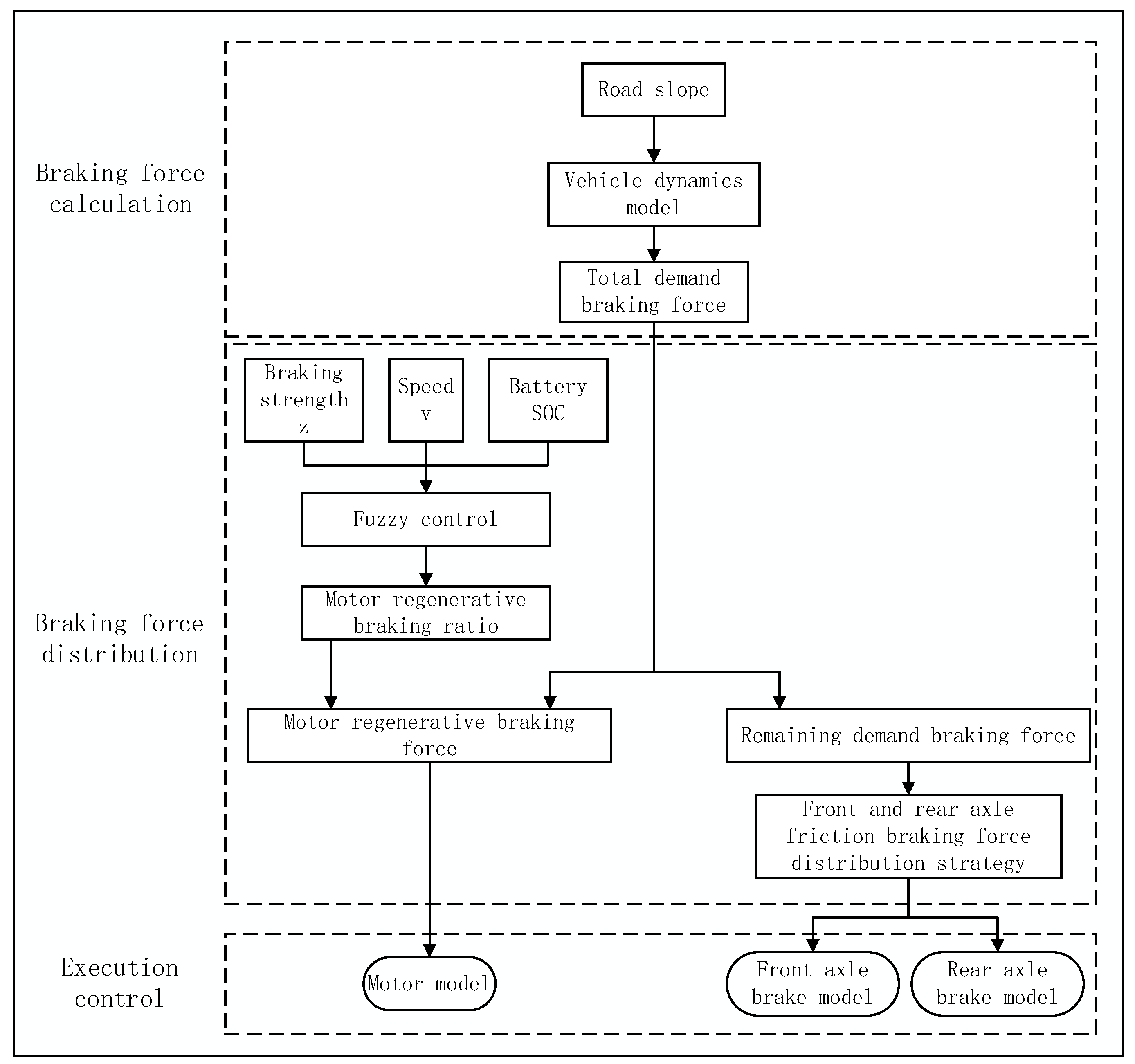
Figure 2.
(a) The membership functions of braking strength z; (b) the membership functions of vehicle speed v; (c) the membership functions of battery SOC; (d) the membership functions of motor regenerative braking force ratio coefficient k.
Figure 2.
(a) The membership functions of braking strength z; (b) the membership functions of vehicle speed v; (c) the membership functions of battery SOC; (d) the membership functions of motor regenerative braking force ratio coefficient k.
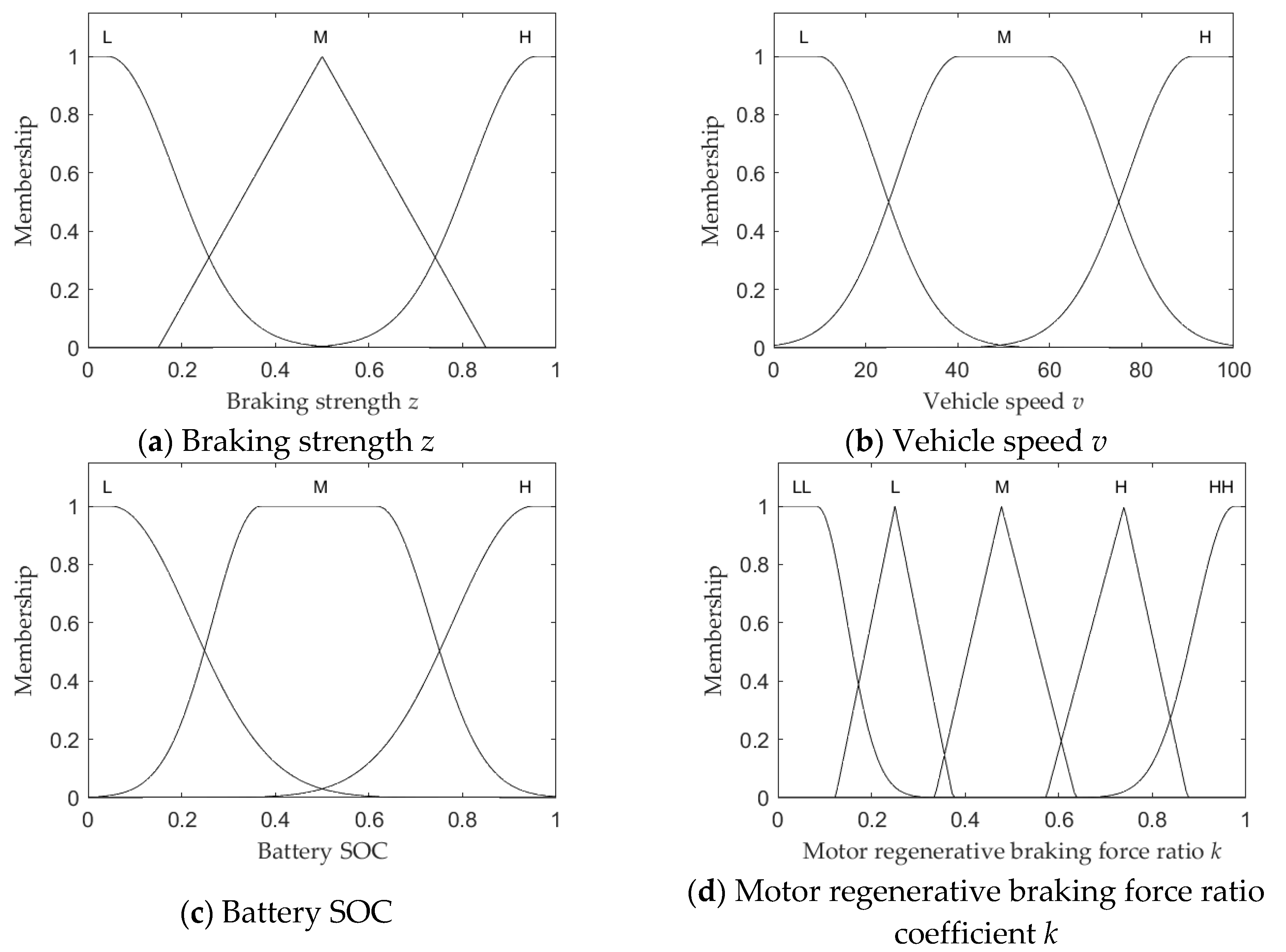
Figure 3.
Front and Rear axle friction braking force distribution curve.
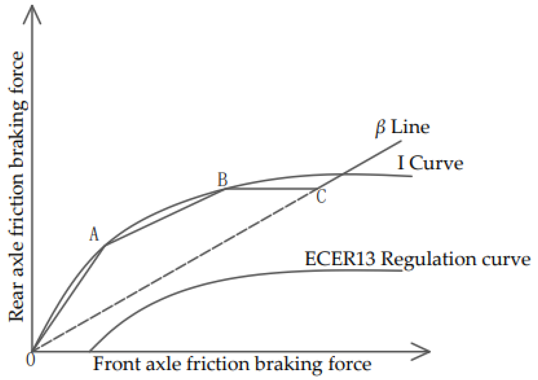
Figure 4.
Control strategy model.

Figure 5.
Vehicle speed and Motor regenerative braking torque.
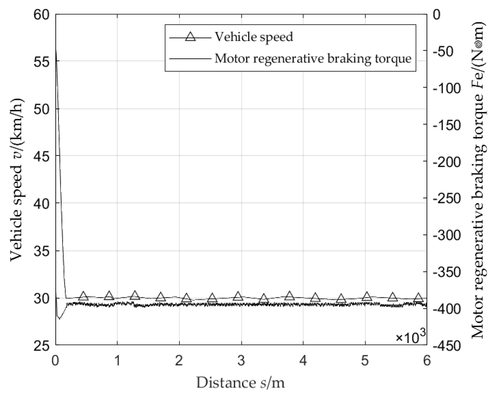
Figure 6.
Battery SOC and Motor regenerative braking torque.
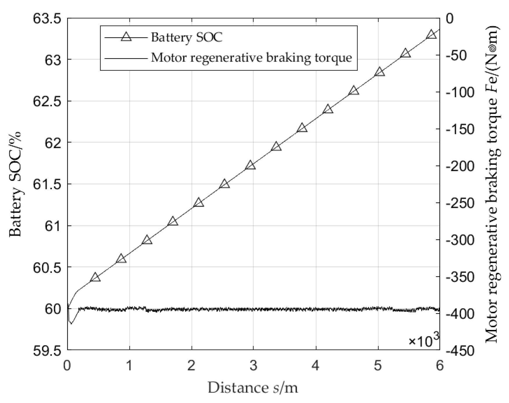
Figure 7.
Front and Rear axle friction braking torque and Motor regenerative braking torque.
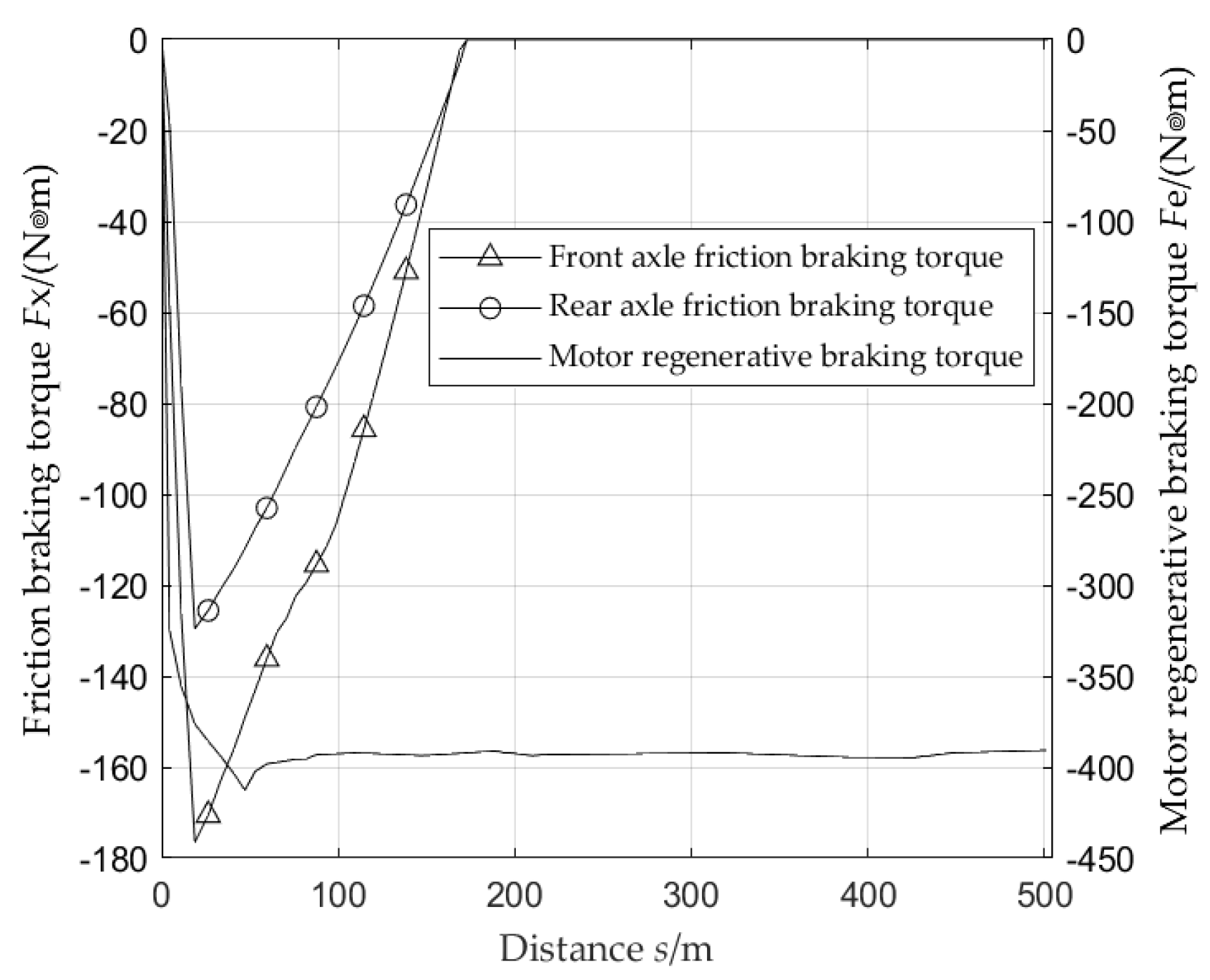
Figure 8.
Road slope.
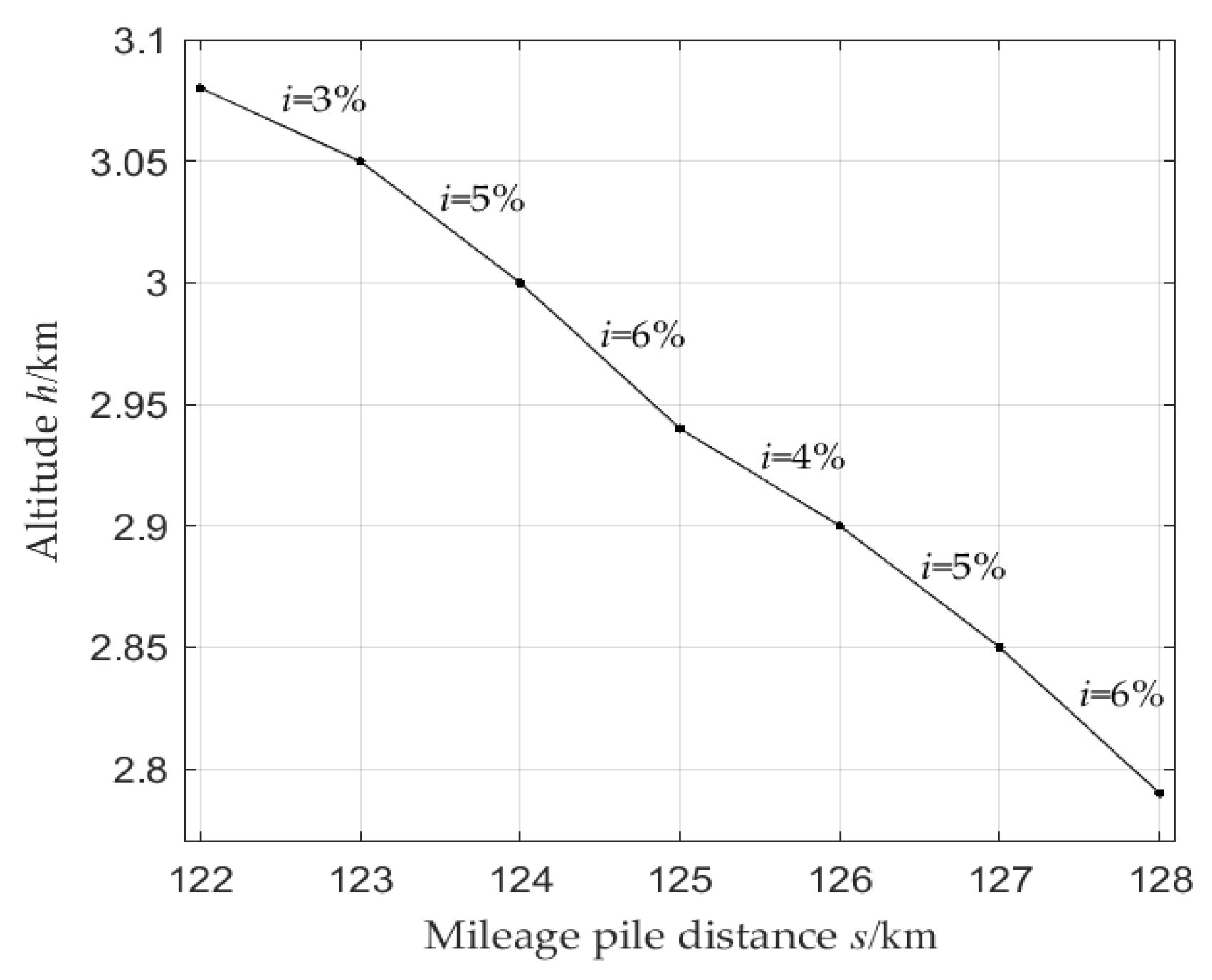
Figure 9.
Vehicle speed and Motor regenerative braking torque.
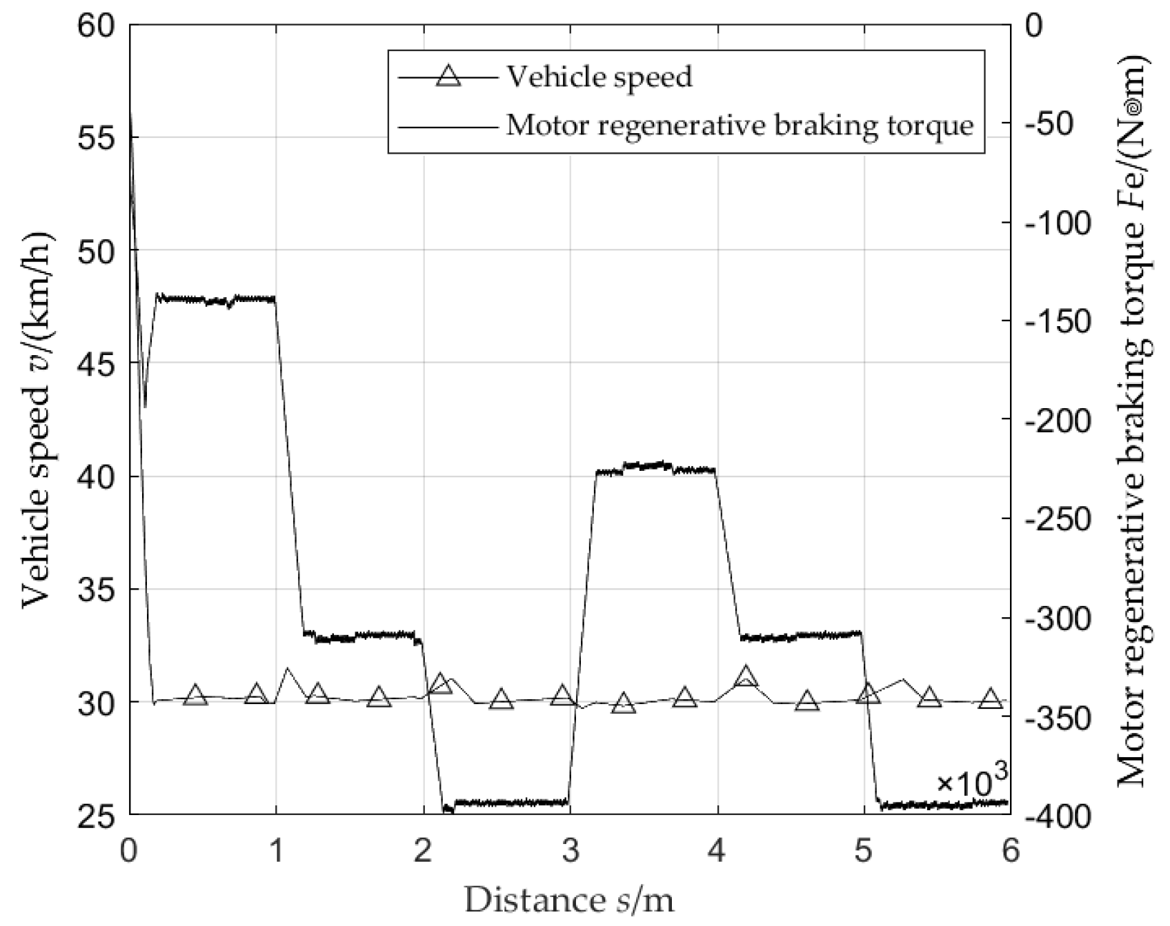
Figure 10.
Battery SOC and Motor regenerative braking torque.
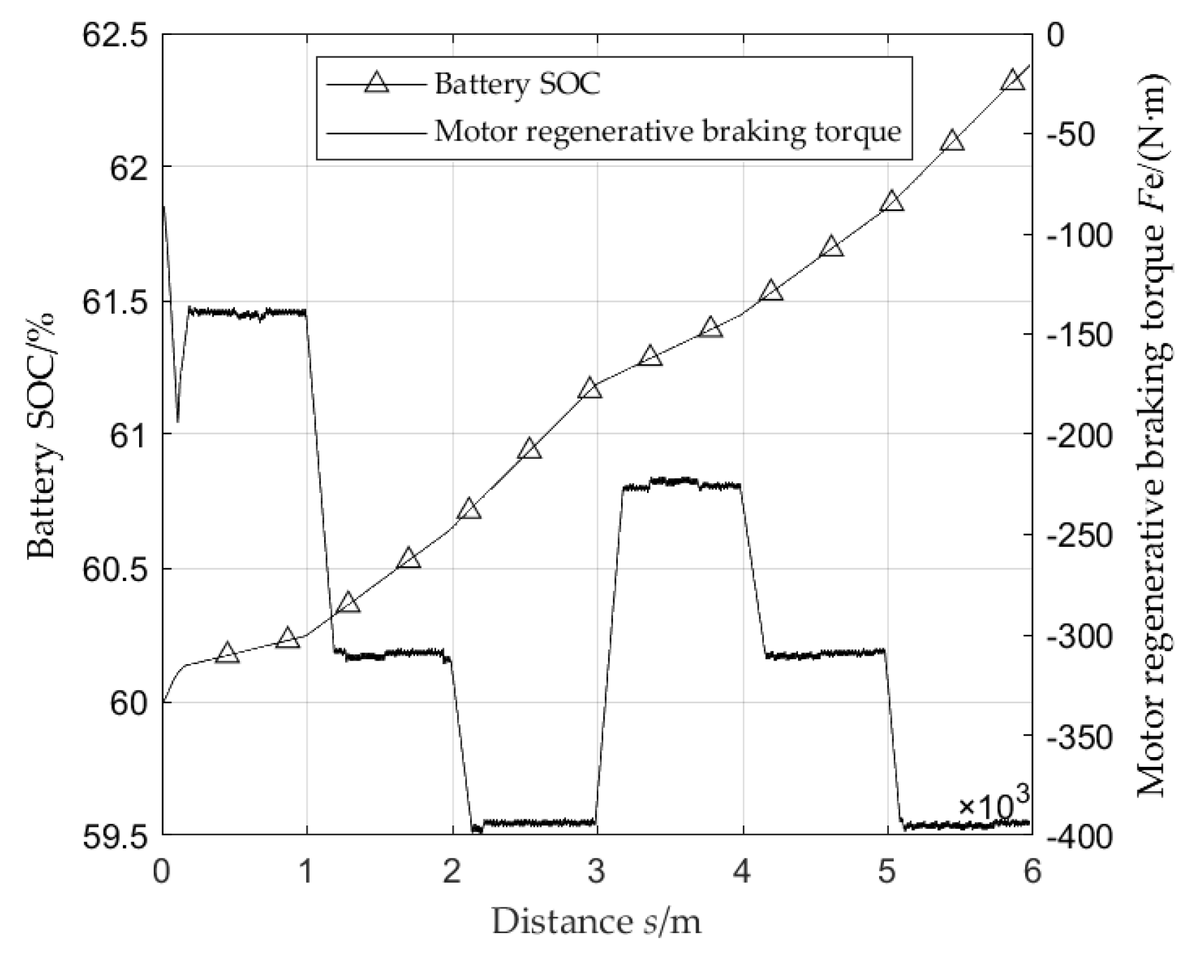
Figure 11.
Front and Rear axle friction braking torque and Motor regenerative braking torque.
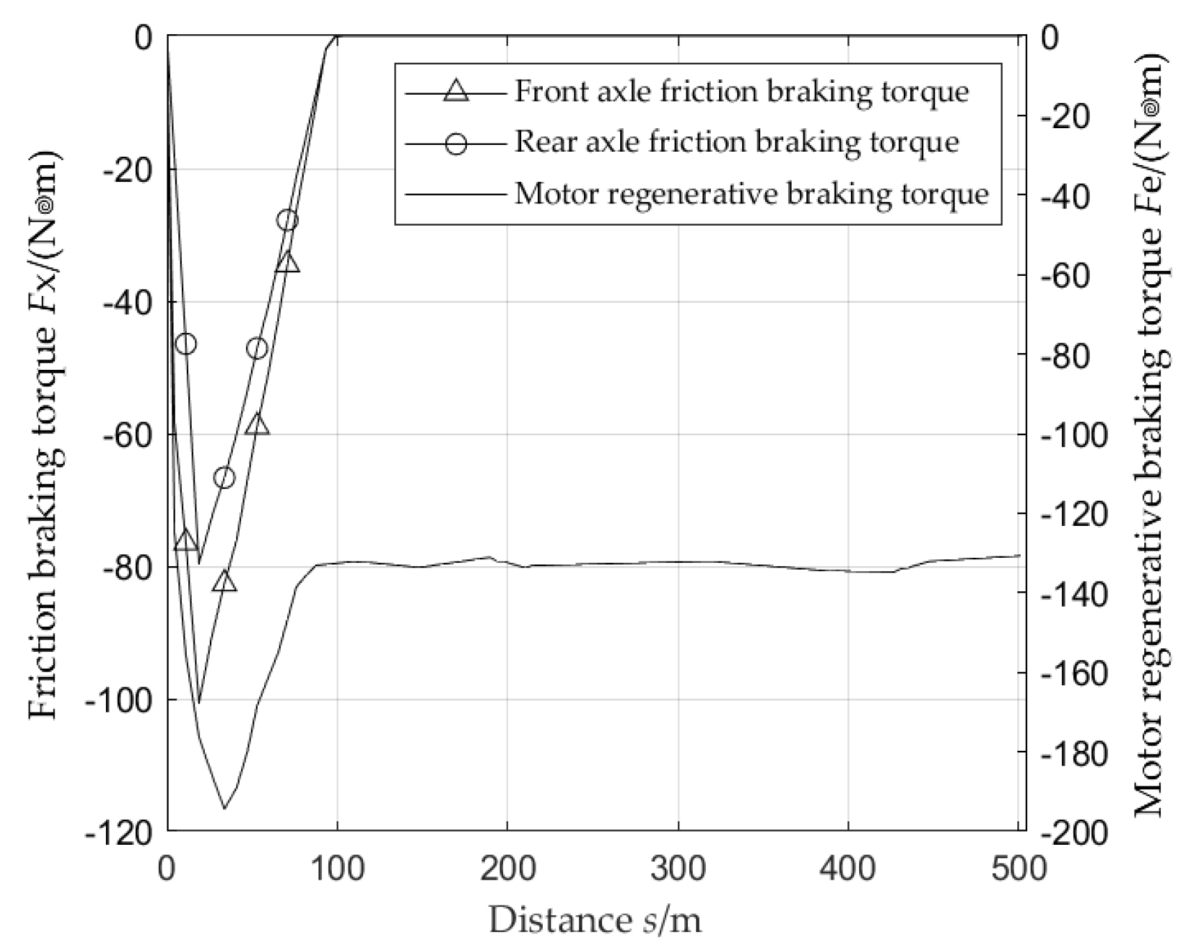

Table 1.
Fuzzy control rules.
| Number | z | v | SOC | k |
|---|---|---|---|---|
| 1 | L | L | L | HH |
| 2 | M | L | L | H |
| 3 | H | L | L | M |
| 4 | L | M | L | H |
| 5 | M | M | L | M |
| 6 | H | M | L | L |
| 7 | L | H | L | M |
| 8 | M | H | L | L |
| 9 | H | H | L | LL |
| 10 | L | L | M | HH |
| 11 | M | L | M | H |
| 12 | H | L | M | M |
| 13 | L | M | M | H |
| 14 | M | M | M | M |
| 15 | H | M | M | L |
| 16 | L | H | M | M |
| 17 | M | H | M | L |
| 18 | H | H | M | LL |
| 19 | L | L | H | L |
| 20 | M | L | H | L |
| 21 | H | L | H | LL |
| 22 | L | M | H | L |
| 23 | M | M | H | L |
| 24 | H | M | H | LL |
| 25 | L | H | H | L |
| 26 | M | H | H | L |
| 27 | H | H | H | LL |
Table 2.
Vehicle parameters.
| Parameter | Value | Parameter | Value |
|---|---|---|---|
| Vehicle curb weight m/t | 3.05 | Rolling resistance coefficient f | 0.08 |
| Vehicle full weight m1/t | 6.15 | Main reducer reduction ratio i0 | 7.05 |
| Vehicle test mass m2/t | 4.05 | transmission efficiency ηt | 0.95 |
| Wheelbase L/m | 4.96 | Motor peak power pm/kw | 320 |
| Distance from front axle to center of mass a/m | 2.05 | Motor peak torque Tm/N‧m | 500 |
| Distance from rear axle to center of mass b/m | 2.91 | Rated power of motor pe/kw | 250 |
| Centroid height hg/m | 0.94 | Rated torque of motor Te/ N‧m | 420 |
| Windward area A/m2 | 5.3 | Maximum battery voltage U/V | 480 |
| Drag coefficient CD | 0.67 | Minimum battery voltage U/V | 400 |
| Wheel radius r/mm | 515 | Number of battery packs | 8 |
Disclaimer/Publisher’s Note: The statements, opinions and data contained in all publications are solely those of the individual author(s) and contributor(s) and not of MDPI and/or the editor(s). MDPI and/or the editor(s) disclaim responsibility for any injury to people or property resulting from any ideas, methods, instructions or products referred to in the content. |
© 2024 by the authors. Licensee MDPI, Basel, Switzerland. This article is an open access article distributed under the terms and conditions of the Creative Commons Attribution (CC BY) license (https://creativecommons.org/licenses/by/4.0/).
Copyright: This open access article is published under a Creative Commons CC BY 4.0 license, which permit the free download, distribution, and reuse, provided that the author and preprint are cited in any reuse.


