1. Introduction
In recent years, quadrotors have been applied in various fields owing to their size, low costs, and capability of VTOL(vertical takeoff and landing) [
1,
2,
3]. These considerable attributes and widespread applications propel significant focus on quadrotors [
4,
5,
6,
7]. In reality, external disturbances and measurement errors are inevitably present [
8,
9,
10,
11,
12]. The key to complete tasks, e.g., power line inspection [
13], logistics transportation [
14], and pesticide spraying [
15] depends on the performance of trajectory tracking. As a result, improving the effectiveness of trajectory tracking control under the influence of external disturbances holds important theoretical significance and practical value, which ensures that quadrotors can meet the flight requirements and avoid uncontrollable crashes.
Nair et al. achieved high-performance tracking for a satellite launch rocket system with time-varying uncertainties by designing an adaptive PID control in reference [
16]. In [
17], an online identification of aerodynamic parameters using the Kalman filter was utilized, followed by compensating the rotor speed using LQR strategy, resulting in improved control performance for heading and altitude. Such works generally linearize the nonlinear dynamics of quadrotors, which leads to approximation errors and performance limitations. In [
18], a fuzzy logic system was used to assess the unmodeled dynamics of the quadrotor. A nonlinear disturbance observer was applied to compensate for external disturbances and assessment error. In reference [
19], the authors proposed a radical basis function neural network (RBFNN) to fix the unknown dynamic problem. To increase the convergence speed and control precision, a fractional-order backstepping control was introduced. Sliding mode control is widely applied in practical systems, e.g., robot manipulation [
20], linear motor positioning [
21], and underwater robots [
22], because of its strong robustness, fast response, and low sensitivity to uncertainties and disturbances. Conventional sliding mode (CSM) cannot guarantee the fast convergence of control system [
23,
24,
25]. Terminal sliding mode (TSM) was designed to deal with this situation [
26]. Besides, CSM may cause chattering. In [
27], a modified second-order sliding mode control was introduced to address the chatting phenomenon. Omid Mofid et al. planed a super-twisting terminal sliding mode control considering input-delay, model uncertainty and wind disturbance for fast response. In [
28], the dynamic model was divided into inner loop and outer loop. Nonsingular terminal sliding mode control (NTSM) was utilized to converge to the desired position and attitude in finite time. In [
29], Hamid Ghadiri et al. proposed a novel adaptive nonsingular terminal sliding mode control (ANTSM). The control signals’ chattering was eliminated. Adaptive estimation was applied to compensate for unknown disturbance. In [
30], the implementation of neural network (NN) approximator was to estimate the model uncertainty. Adaptive algorithms were designed to make up for the approximation error and update the NN weight matrix. Nonsingular fast terminal sliding mode control (NFTSMC) was presented to guarantee the finite-time convergence of the quadrotor to its desired trajectory. An NN-NFTSMC algorithm was formulated to provide the system with robustness in the presence of the model uncertainty and external disturbance. In [
31], Mo H et al. took efforts to make comprehensive survey of control techniques for quadrotors. In this study, adaptive terminal sliding mode is the most appropriate method for quadrotor tracking control.
To develop a control scheme for full trajectory tracking of 6 DOF quadrotor’s position and attitude, an adaptive backstepping fast nonsingular integral terminal sliding mode (ABFNITSM) control is proposed to track desired attitude. The position loop is based on adaptive integral backstepping control. The main contributions of this article can be summarized as follows:
A new control strategy is introduced for quadrotors under external disturbances.
The proposed ABFNITSM control is characterized by strong robustness against nonlinearities and external disturbances compared to traditional control. Furthermore, it is also in possession of capabilities of fast response and precise tracking.
The implementation of adaptive estimation enables update of controller parameters online, which simplifies the tuning process. Besides, dead zone technique is employed to compensate for disturbances.
A new saturation function, which is differentiable, is utilized to eliminate chattering.
Lyapunov theory guarantees the stability of the quadrotor trajectory tracking control system.
This article is organized as follows: the derivation of the quadrotor dynamic model is introduced in
Section 2. The adaptive backstepping fast nonsingular integral terminal sliding mode for attitude control and the adaptive integral backstepping for position control are designated in
Section 3. Meanwhile, the stability of the control system is proven using Lyapunov theory. In
Section 4, the simulation result is presented, followed by the conclusion.
2. Dynamic model of the quadrotor
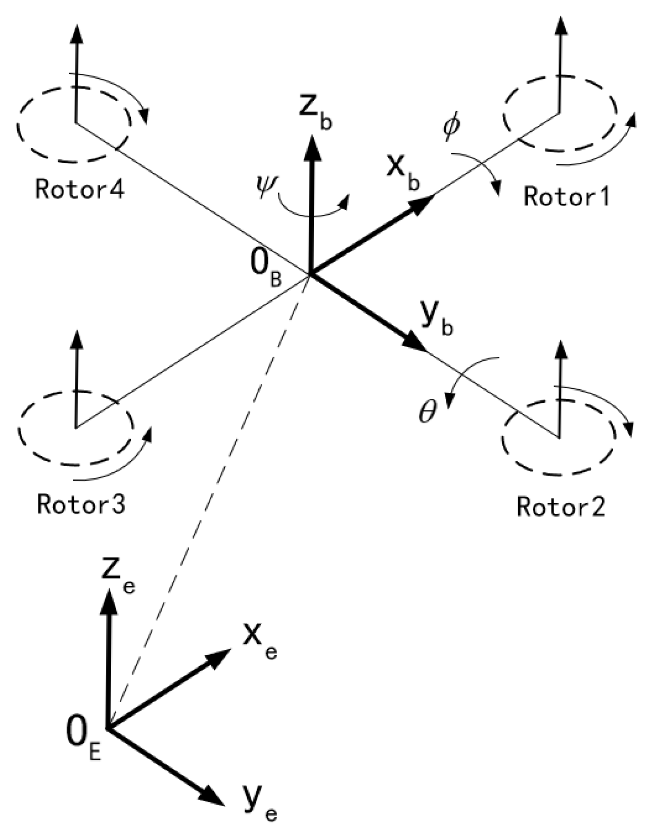
The quadrotor is an underactuated system. The vector
represents the translational motion and the vector
denotes the Euler angle.
Figure 1 shows a schematic diagram of the quadrotor.
This paper adopts the right-hand rule to define body reference frame (BRF) and inertial reference frame (IRF) to describe the 6DOF rigid-body motion of the quadrotor. x, y, and z represent longitudinal, lateral, and vertical translational motion respectively. , , and are roll, pitch, and yaw angle respectively.
According to Newton-Euler principle, the system model can be written:
is the aerodynamic force in the inertial frame.
is the thrust produced by the i-th motor.
describes the rotational speed of the motor.
represents the lift coefficient of the motor.
is the transformation matrix from the BRF to the IRF.
is the gravitational force.
represents the force due to air resistance.
is the inertia matrix of the quadrotor. Based on the assumptions in
Appendix A,
is defined as follows:
The notation
means the cross-product operator. Based on the vector
, it defines a skew-symmetric matrix.
denotes the aerodynamic torque produced by motors.
is the distance between the rotation axis of one motor and the center of gravity.
is the torque coefficient of one motor during rotation.
stands for the torque caused by the gyroscopic effect.
reflects the torque owing to air friction.
Actually, a quadrotor undergoes various problems such as inaccurate parametric (mass and inertia) measurement, control effectiveness and external disturbances. These throw obstacles in control design. In order to formulate the control problem, equation (2) is rewritten incorporating matched/unmatched uncertainties as
where
and
represent uncertainty in mass, inertia and control effectiveness, respectively. According to lemma1, the above equation can be re-written as:
where
and
are lumped uncertainties.
where
,
,
,
, and
is unit diagonal matrix.
The relationships between the angular velocity of a quadrotor in BRF and the angular velocity in IRF are represented as follows:
According the small angle approximation principle, the transformation matrix can be approximated as the identity matrix.
The vector denotes the state variables.
The virtual position control inputs are defined as follows:
The equation (13) can be rewritten as follows:
where:
3. Control design
This section is committed to the design of trajectory tracking control and stability analysis. Taking parametric uncertainties and external disturbances into consideration, a trajectory tracking control strategy is formulated to ensure quick and accurate tracking of reference commands. To achieve this goal, a new control is proposed integrating terminal sliding mode, integral element, backstepping technique and dead zone technique for attitude trajectory tracking. For the sake of chattering elimination, a new saturation function is designed. Additionally, an online adaptive estimation technique is introduced to compensate for parametric uncertainties and external disturbances. Adaptive integral backstepping control is introduced in position loop.
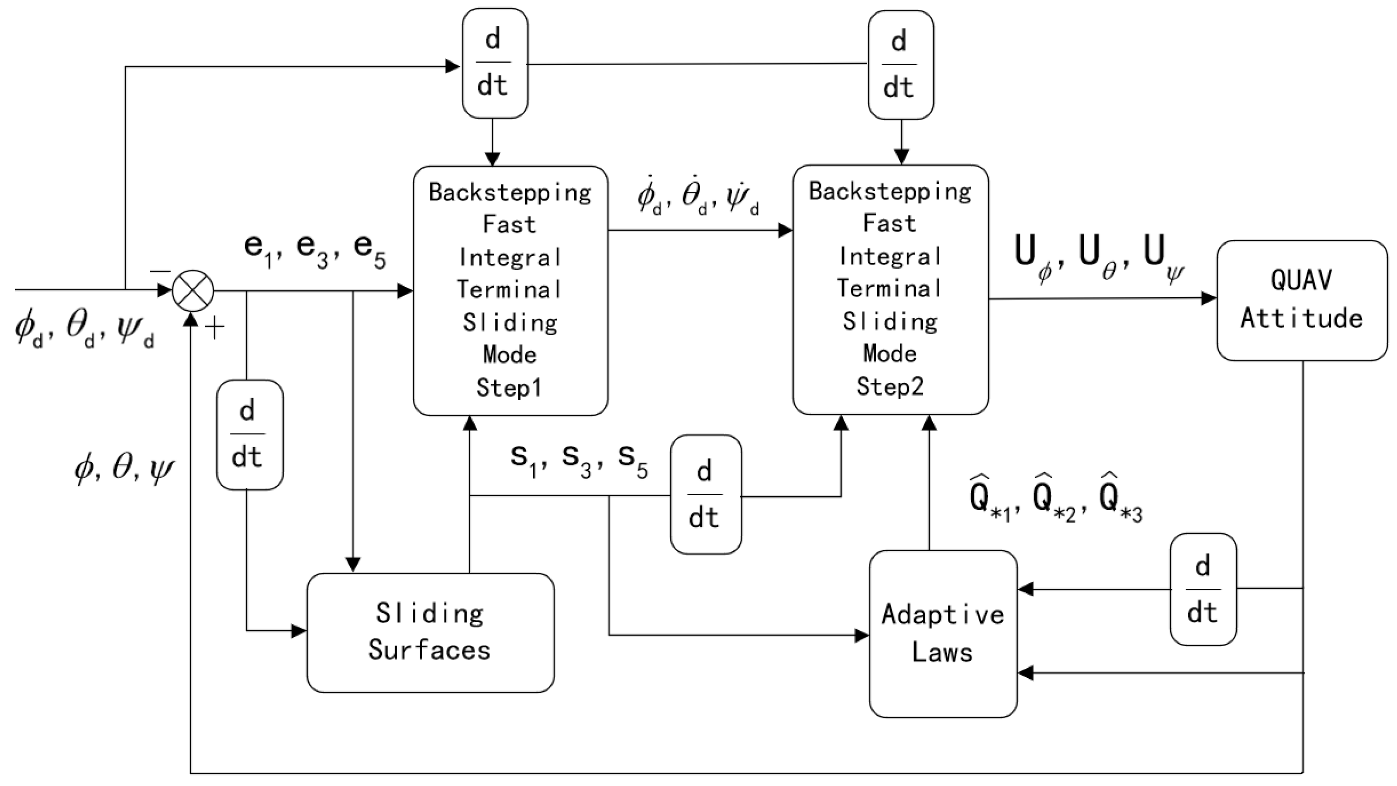
Figure 2 illustrates the entire control flow diagram.
3.1. Position tracking control design
The adaptive integral backstepping (AIBS) control exhibits good robustness. It combines the characteristics of integral backstepping control and adaptive estimation to facilitate precise tracking and stable control. The basic idea of backstepping method is to gradually introduce virtual control variables and recursively design control laws to guide the tracking errors from an initial state to zero. An adaptive law is used to compensate for modeling errors, external disturbances, and measurement noise. The design process of AIBS is depicted as follows:
Figure 3.
Block diagram of AIBS.
Figure 3.
Block diagram of AIBS.
The position tracking error is defined as follows:
where
,
, and
are desired trajectory. The time derivative of equation (18) is:
The Lyapunov function is defined as follows for stable system:
where:
The time derivative of equation (20) is:
The system virtual control input is selected as follows:
where
,
, and
are positive constants to be designed.
Substituting (23) into (22) yields:
The second tracking error is given by:
The Lyapunov function can be defined as follows:
The time derivative of equation (26) is:
Substituting (19), (23), and (25) into (27) generates:
To ensure the stability of the position tracking control system, we need to satisfy the following condition:
where
,
, and
are the estimation of
,
, and
respectively.
From (29), the corresponding position control law can be derived as follows:
To prove the stability of the system and determine the parametric values of
,
, and
,
is taken as an illustration. The Lyapunov function is formulated as follows:
where
is positive constant,
is the estimation error.
The time derivative of equation (31) is:
If the third term on the right-hand side of (32) is set to 0, it can be deduced that:
Therefore, the subsystem is stable.
For the purpose of establishing a complete proof, the Lyapunov function is defined as follows:
The time derivative of the (36) is:
where
,
,
,
,
, and
are positive constants.
The stability proof of the position tracking system is now completed.
where
,
, and
are positive constants under design.
Based on (15), thrust and the desired attitude angle can be calculated as follows:
3.2. Attitude tracking control design
The previously proposed AIBS control has been effective in position tracking, ensuring the stability of the position subsystem. In this section, a robust adaptive backstepping fast nonsingular integral terminal sliding mode control (ABFNITSM) is proposed for attitude tracking. A new saturation is designed to eliminate chattering. The main objective of this control is to ensure system stability and achieve fast convergence of the Euler angle to the desired trajectory.
Figure 4.
Block diagram of ABFNITSM.
Figure 4.
Block diagram of ABFNITSM.
The saturation function is designed as follows:
The attitude tracking error is defined as follows:
where
,
, and
are desired trajectory. The time derivative of equation (40) is:
The Lyapunov function is defined as follows:
The time derivative of the (42) is:
The system virtual control input is selected as follows:
The sliding mode function is chosen as follows:
where
are positive constants to be designed.
With the sliding function
to be differentiable and the system to exhibit Hurwitz stability for
, the controller parameters aforementioned must satisfy the following condition:
The time derivative of equation (45) is:
To ensure system stability, the following Lyapunov function is defined as follows:
The time derivative of equation (48) is:
Substituting (44) into (49) derives:
With the intention of system stability, the second term on the right-hand side of equation (50) is expected to be equal to zero.
Neglecting the uncertainty term (i.e.,
) and substituting (47) into (51), the equivalent control input is calculated as follows:
Then, the reaching law is selected as follows:
where
and
are controller parameters that need to be designed and are greater than zero.
is the estimation of the parameters related to uncertainties, which is updated by the following adaptive estimation algorithm
:
where
are positive constants that need to be confirmed.
In practical applications, the sliding variables
,
, and
often encounter chattering due to measurement noise, leading to overestimation of
. To alleviate this issue, dead-zone technique is used to adjust the adaptive law.
where
represents the threshold for the deviation caused by influencing factors (such as sensor noise, uncertainty in estimation and inertia delay of the motor). In this article,
is set to 0.3.
Adding the equivalent input and the convergence control input together yields the total control input:
The Lyapunov function is defined as follows:
represents the estimation error. The time derivative of equation (57) is given as follows:
Substituting (44), (47), and (56) into (58) produces:
where:
Based on the provided information and equations, the stability of system is proven.
4. Results
This section presents simulation results to validate the performance of the proposed control. During simulation tests, the initial position and attitude are set to
m and
rad, respectively. The static parameters and control system parameters are listed in
Table 1 and
Table 2 respectively.
The proposed control is compared with the integral backstepping control and integral terminal sliding mode. The simulations are performed with external disturbances caused by wind gusts or other factors.
The external disturbances are assumed to follow Gaussian distribution. The "Random Number" block in Simulink is utilized to generate random numbers with a mean of 0 and a standard deviation of 10 as disturbances. The sampling time is set to 2s. To ensure that the disturbances in the position loop stay within the range of -1.5 to 1.5 and that the disturbances in the attitude loop stay within the range of -2 to 2 , the generated random numbers should be multiplied by appropriate scaling factors.
4.1. Case1
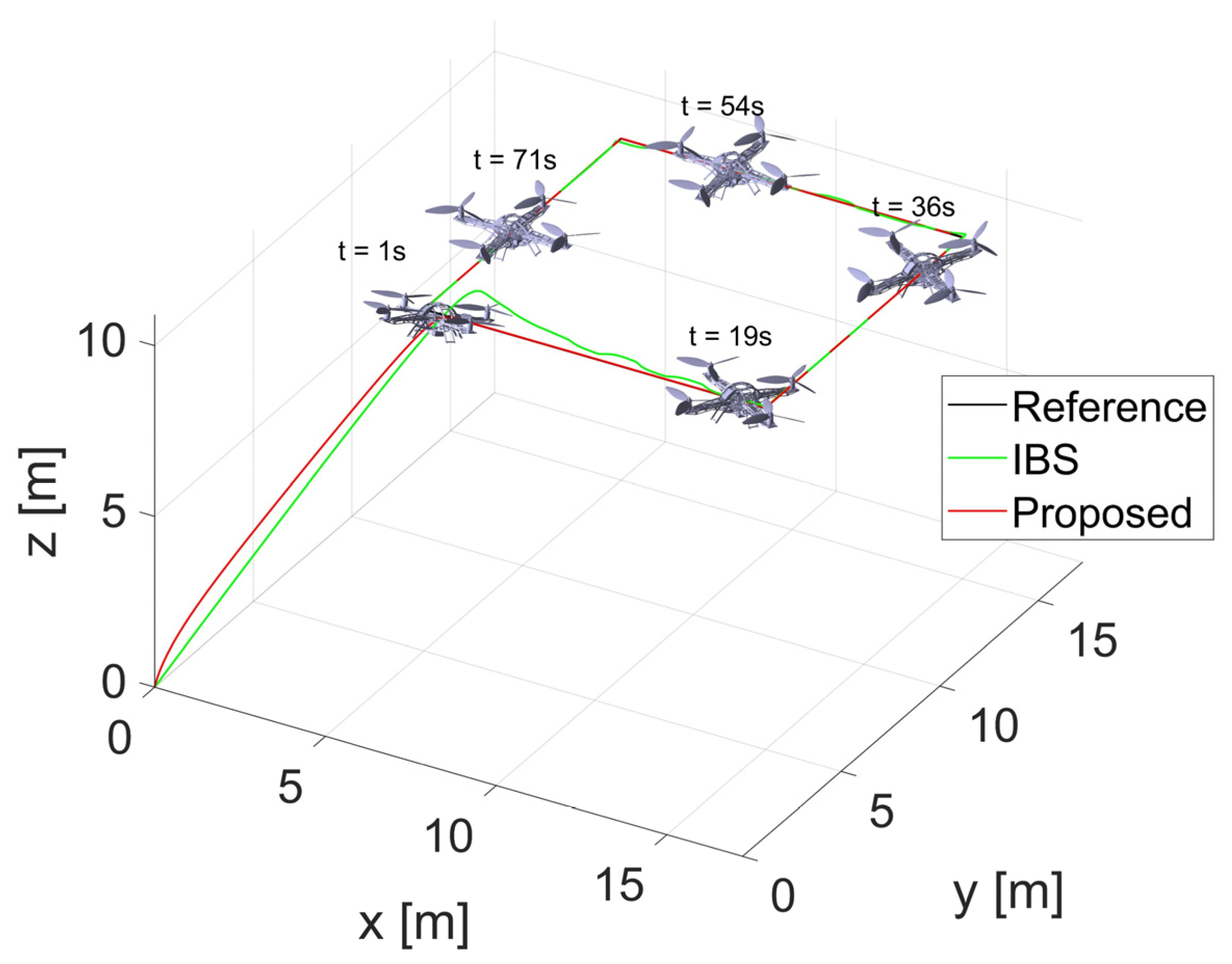
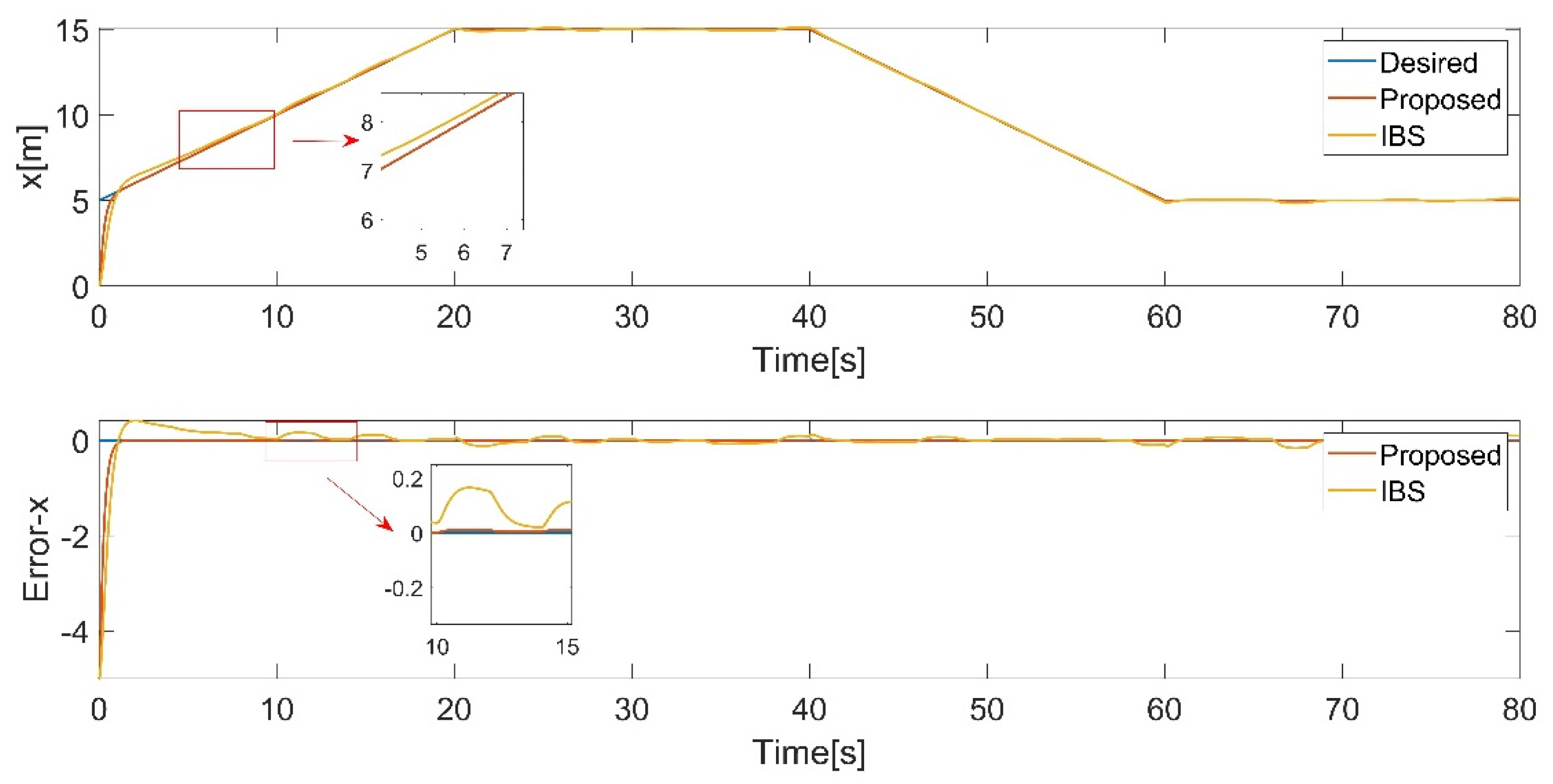
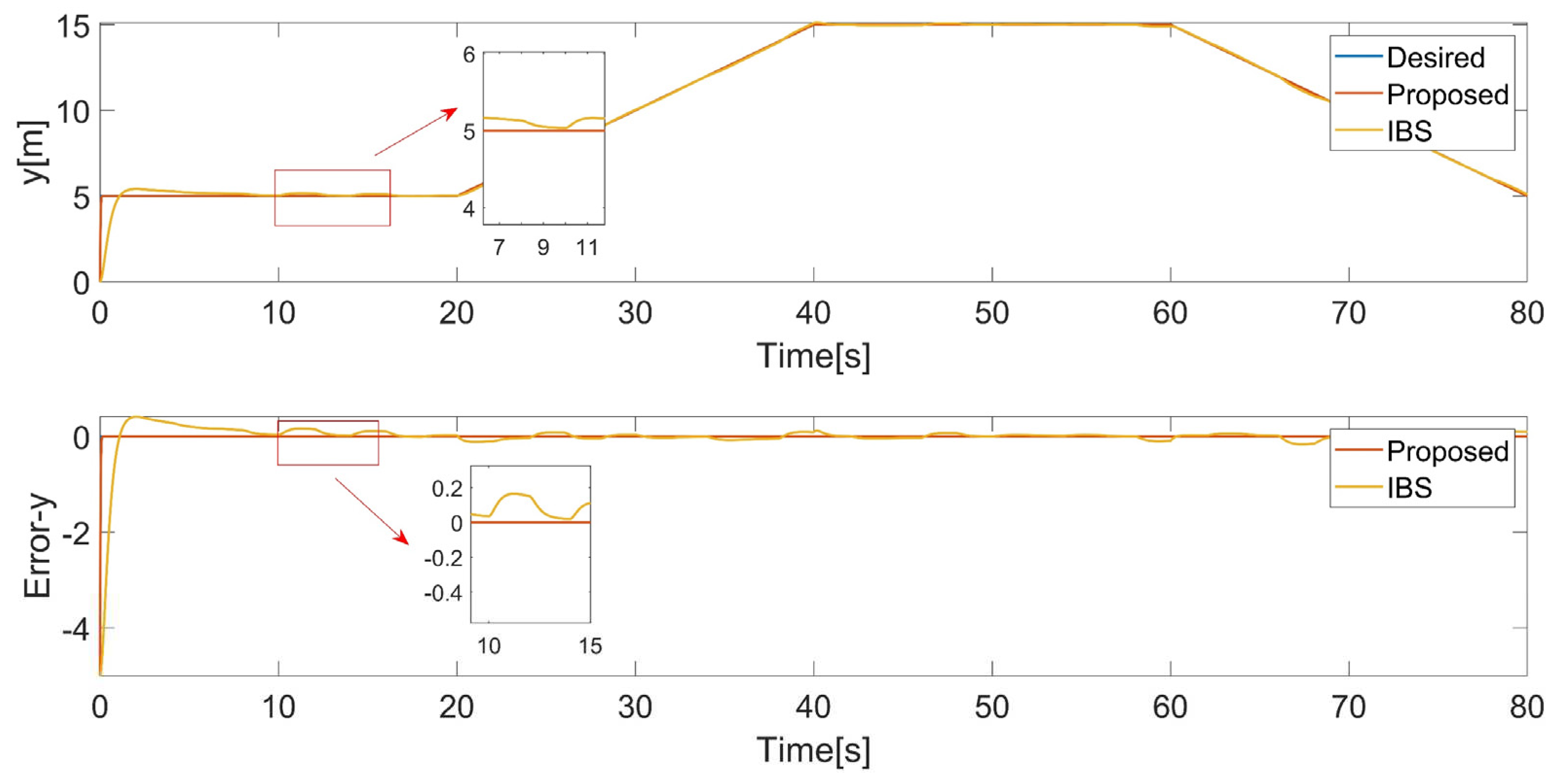
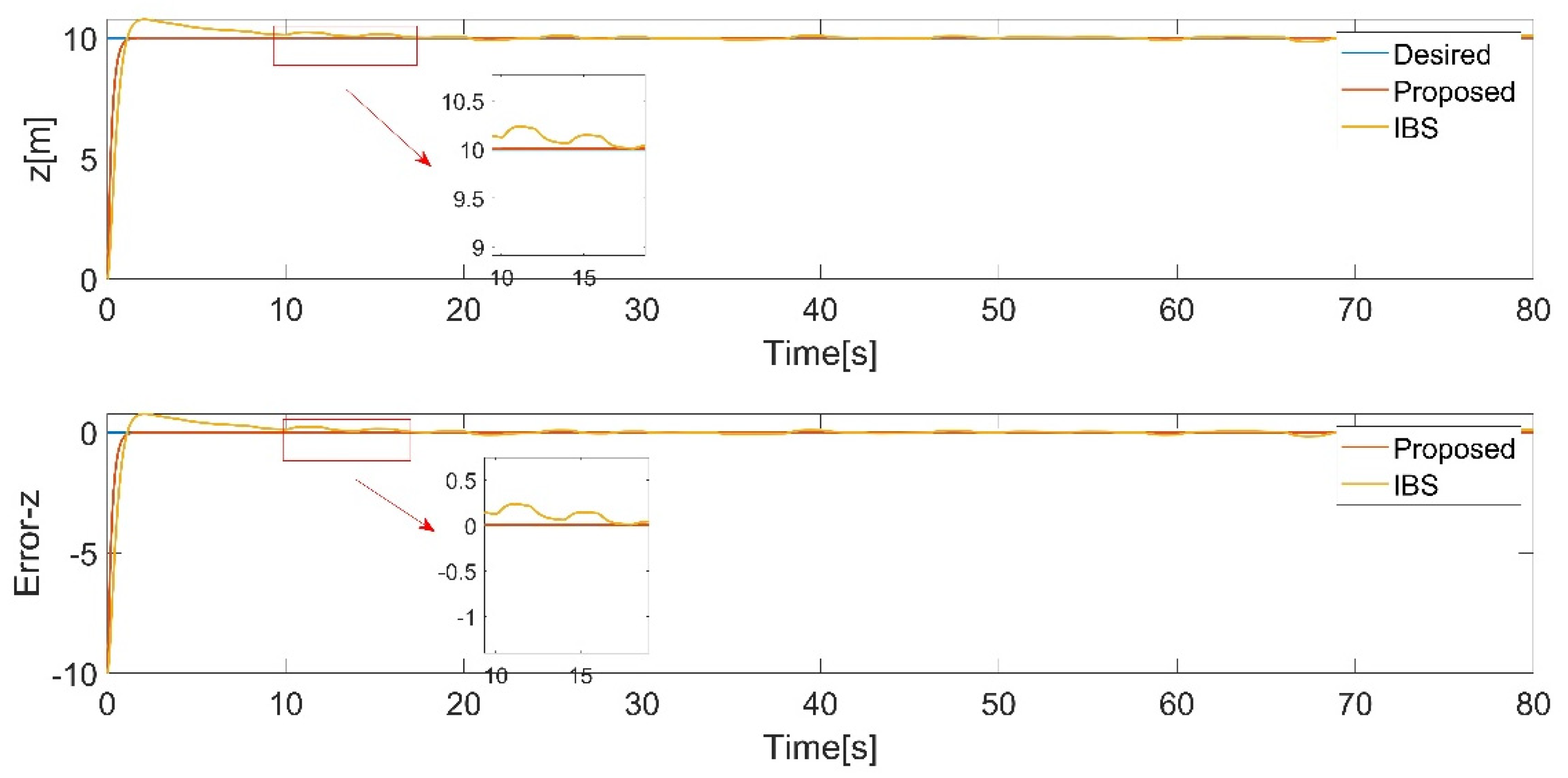
In this case, the quadrotor is demanded to track a simple rectangle trajectory. External disturbances are taken into account. A 3D trajectory plot provides a visual representation of the tracking performance of a control (
Figure 5). It allows for a comprehensive view of how well the control is able to follow the desired trajectory in 3D space. The simulation results are presented in
Figure 6,
Figure 7,
Figure 8,
Figure 9,
Figure 10 and
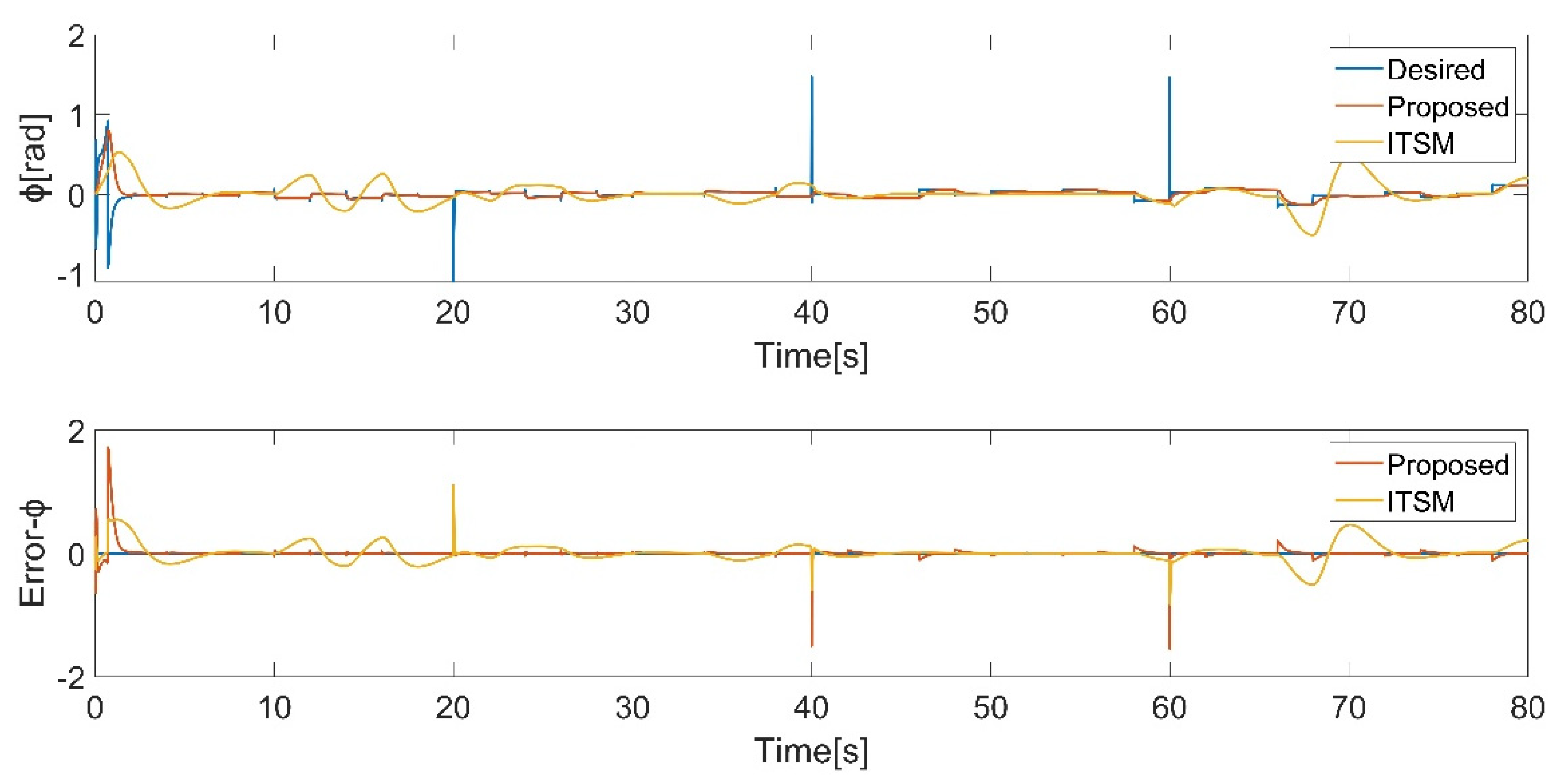
Figure 11. To provide a more intuitive representation of the control performance, error curves for the
,
,
directions and Euler angles are plotted.
The desired trajectory are defined as follows:
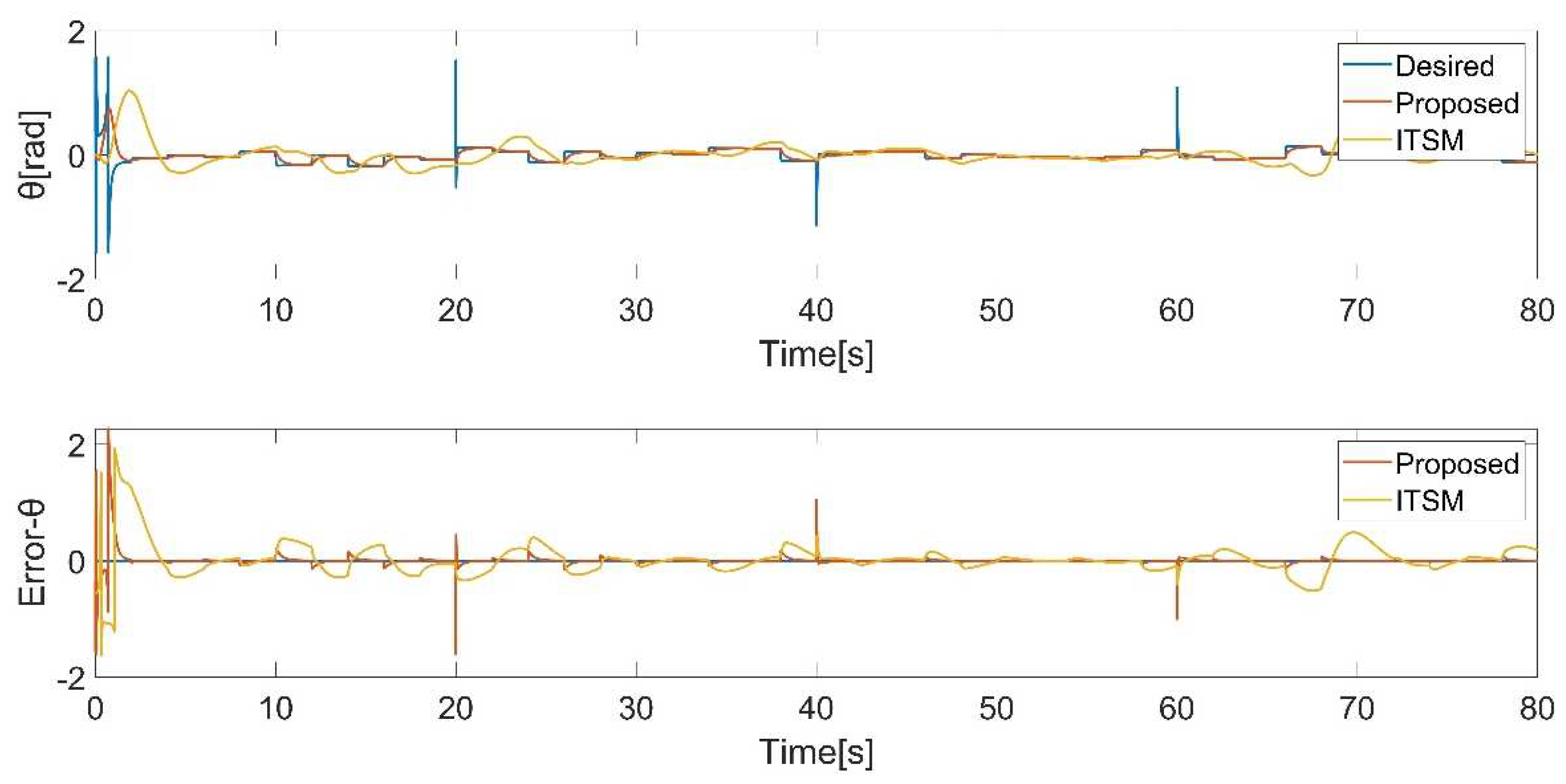
Due to that the initial position and attitude are set to 0, the quadrotor attempts to approach the desired trajectory quickly, which results in excessively large desired roll and pitch angles during the initial stages of the simulation, leading to significant tracking errors.
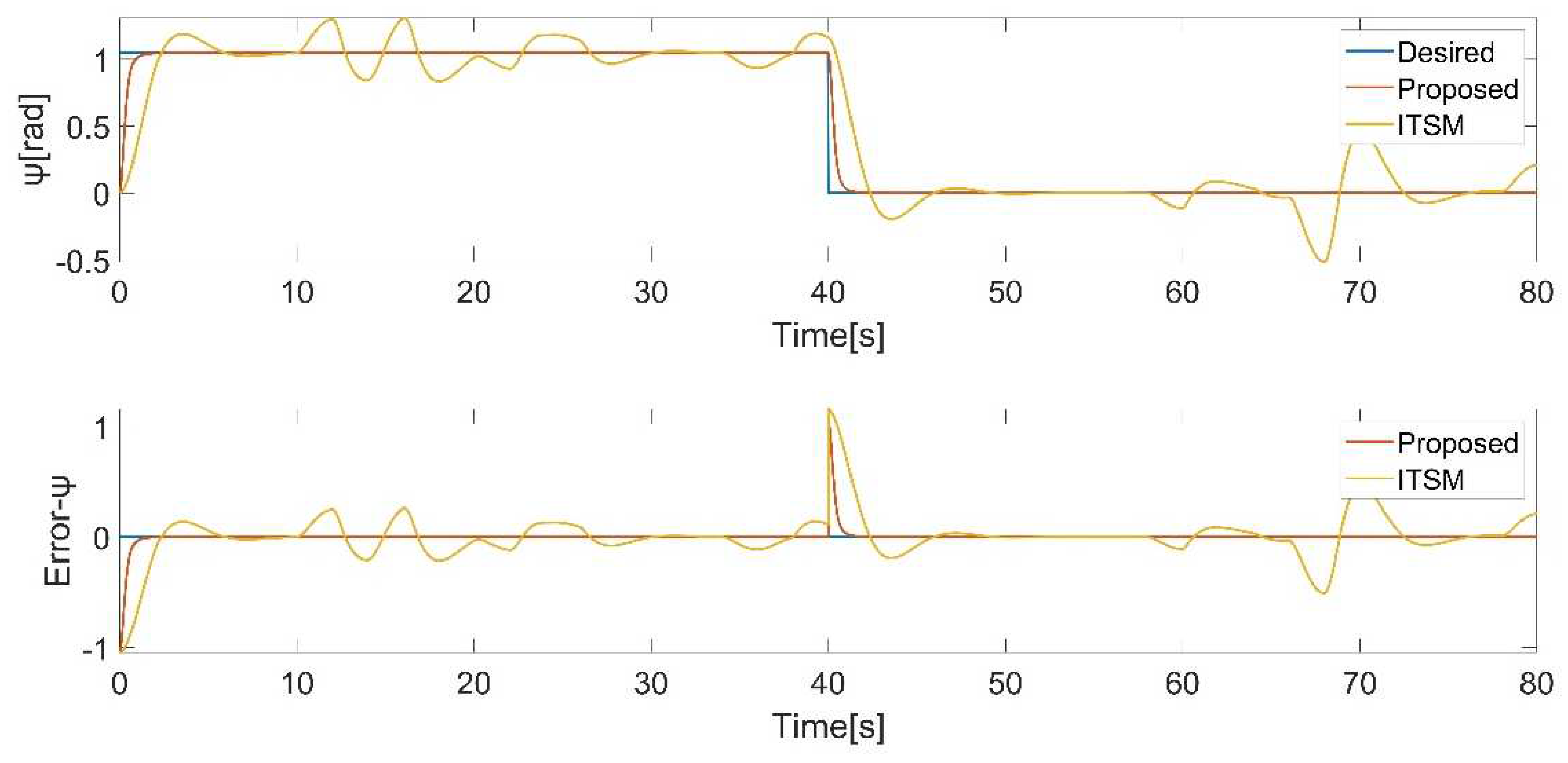
The results demonstrate that both controllers track the desired position and attitude in the presence of disturbances in
Figure 5 and
Figure 9,
Figure 10 and
Figure 11, while the proposed controller behaves excellently. Even when there is a sudden change in the yaw angle, the proposed controller still rapidly reacts and tracks the new trajectory in
Figure 11. Through comparison, it is evident that the proposed controller exhibits better performance.
Finally, by comparing with IBS-ITSM, the proposed controller possesses better performance. The square trajectory used in this case is relatively simple. In the next case, a more complex trajectory will be employed to further demonstrate the supremacy of the proposed controller.
4.2. Case2
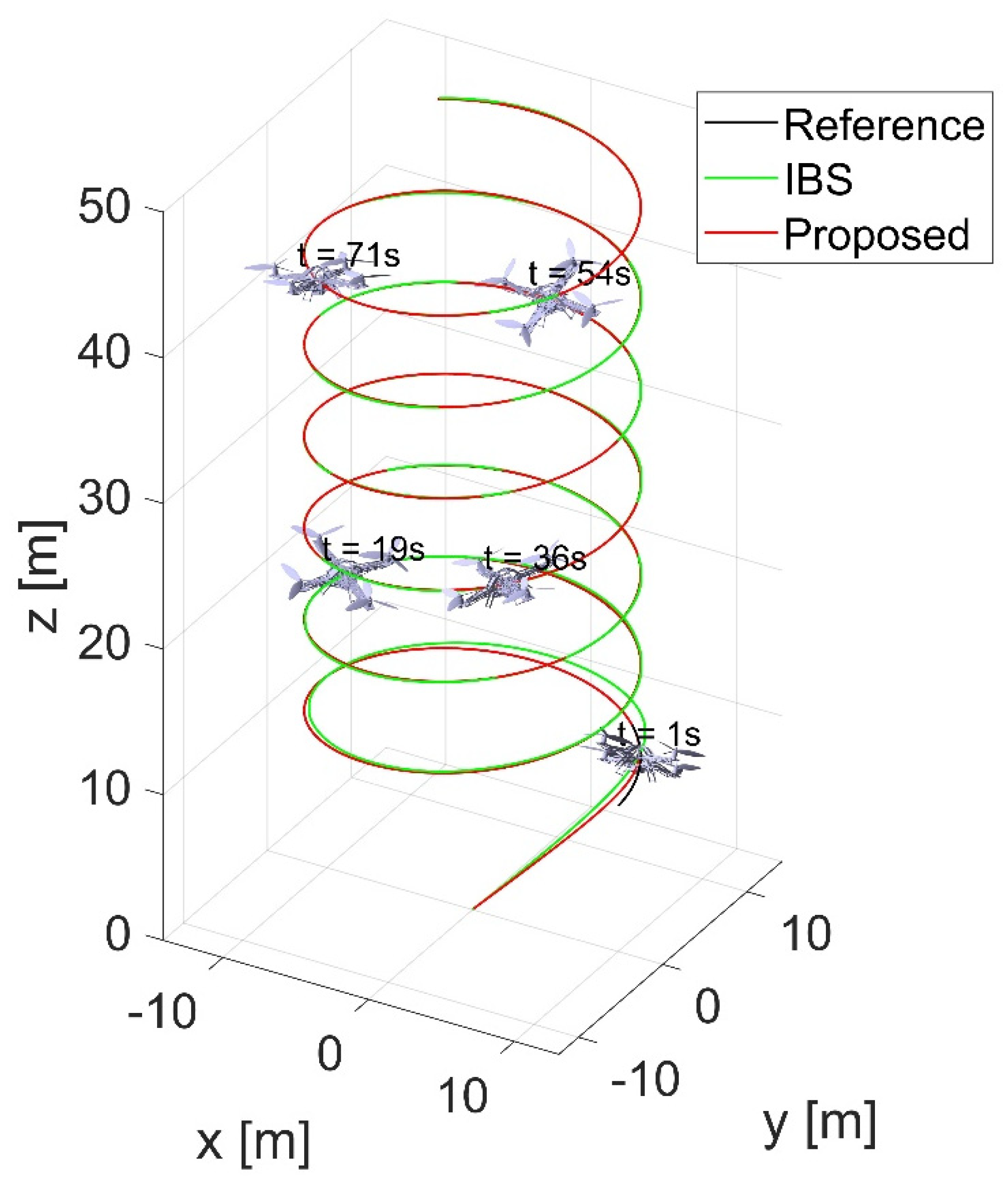
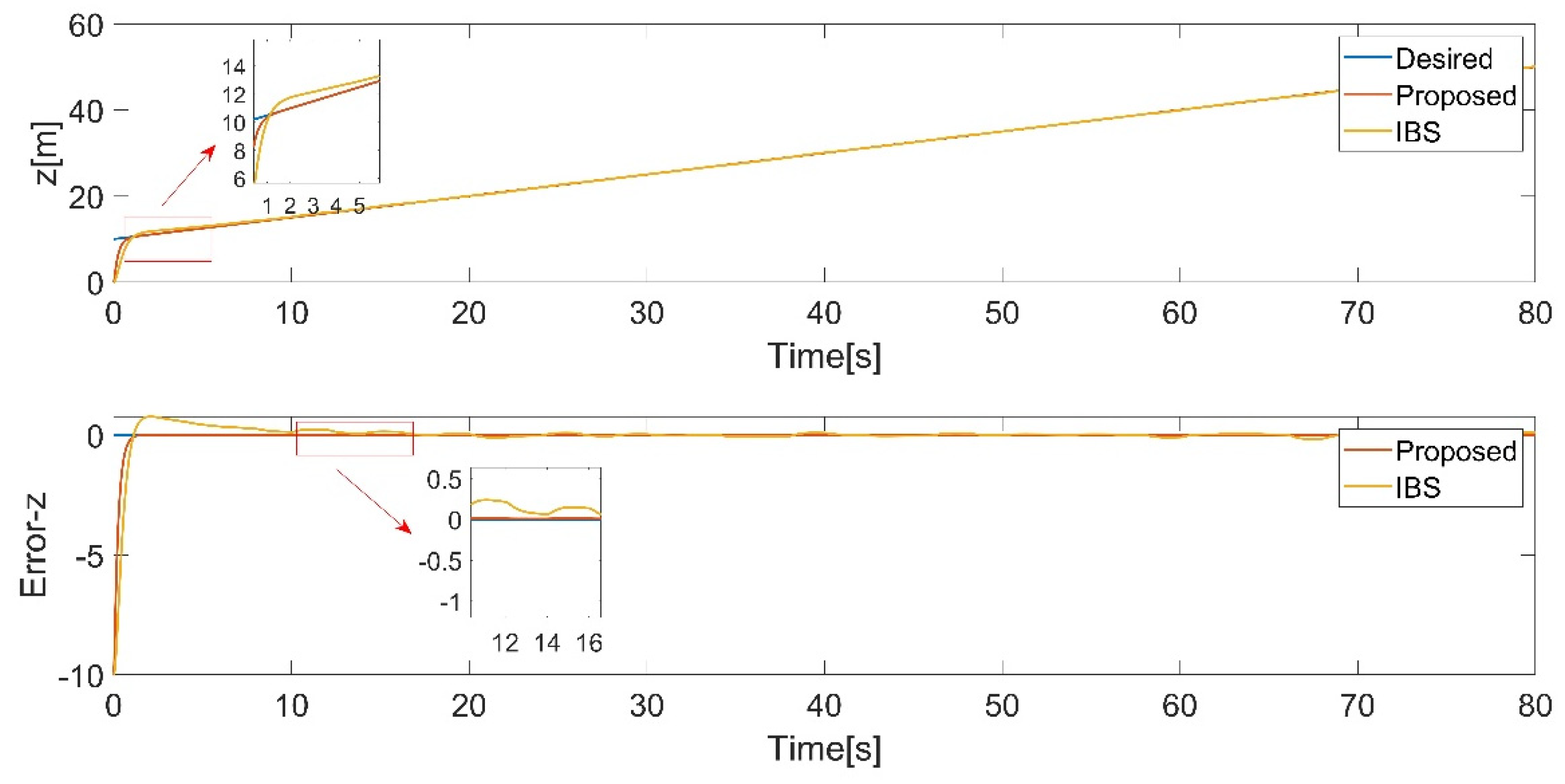
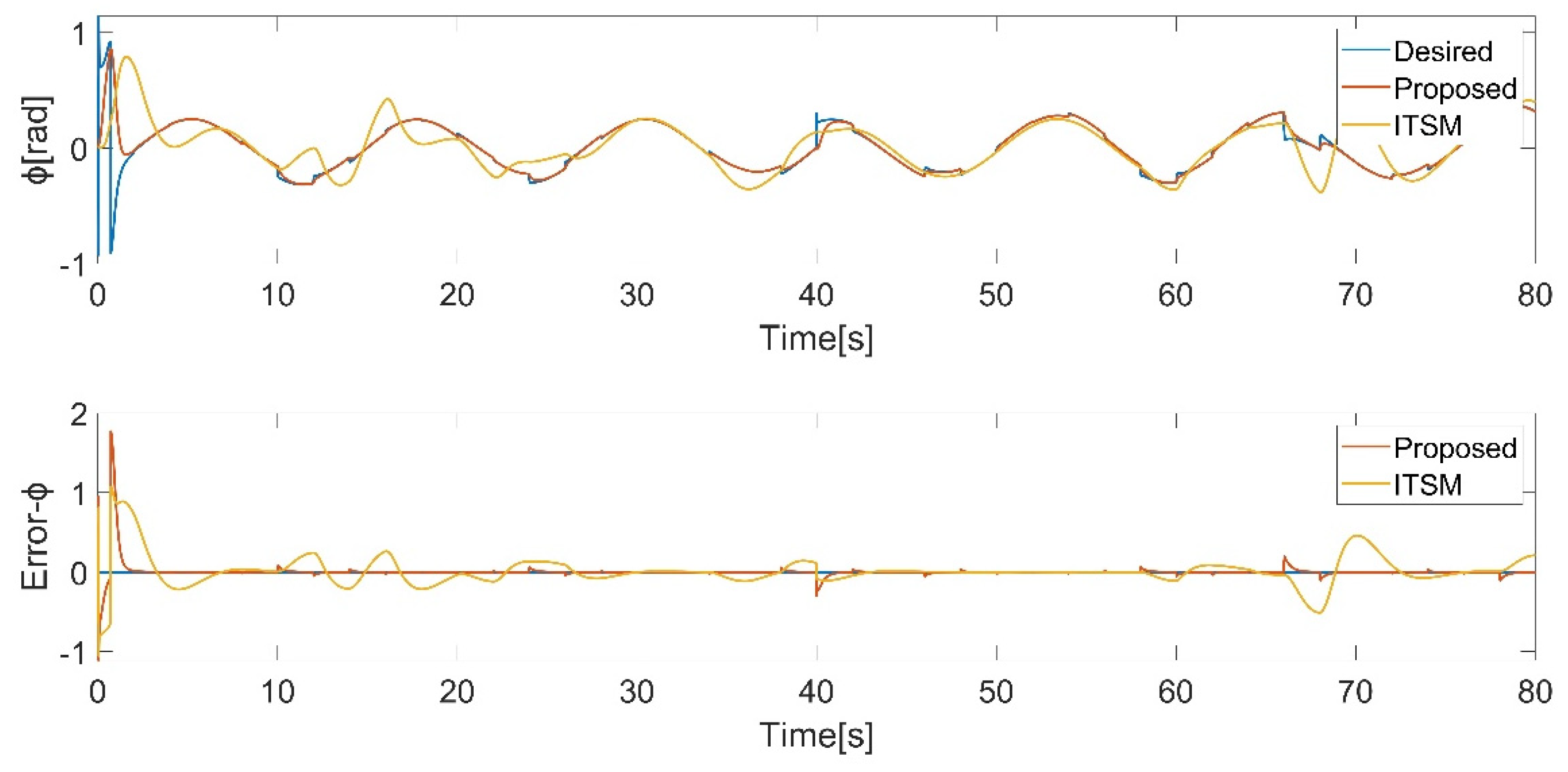
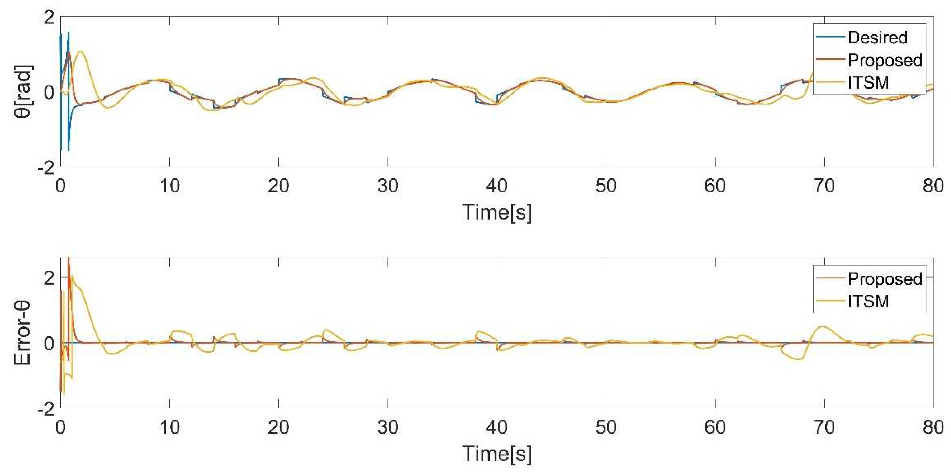
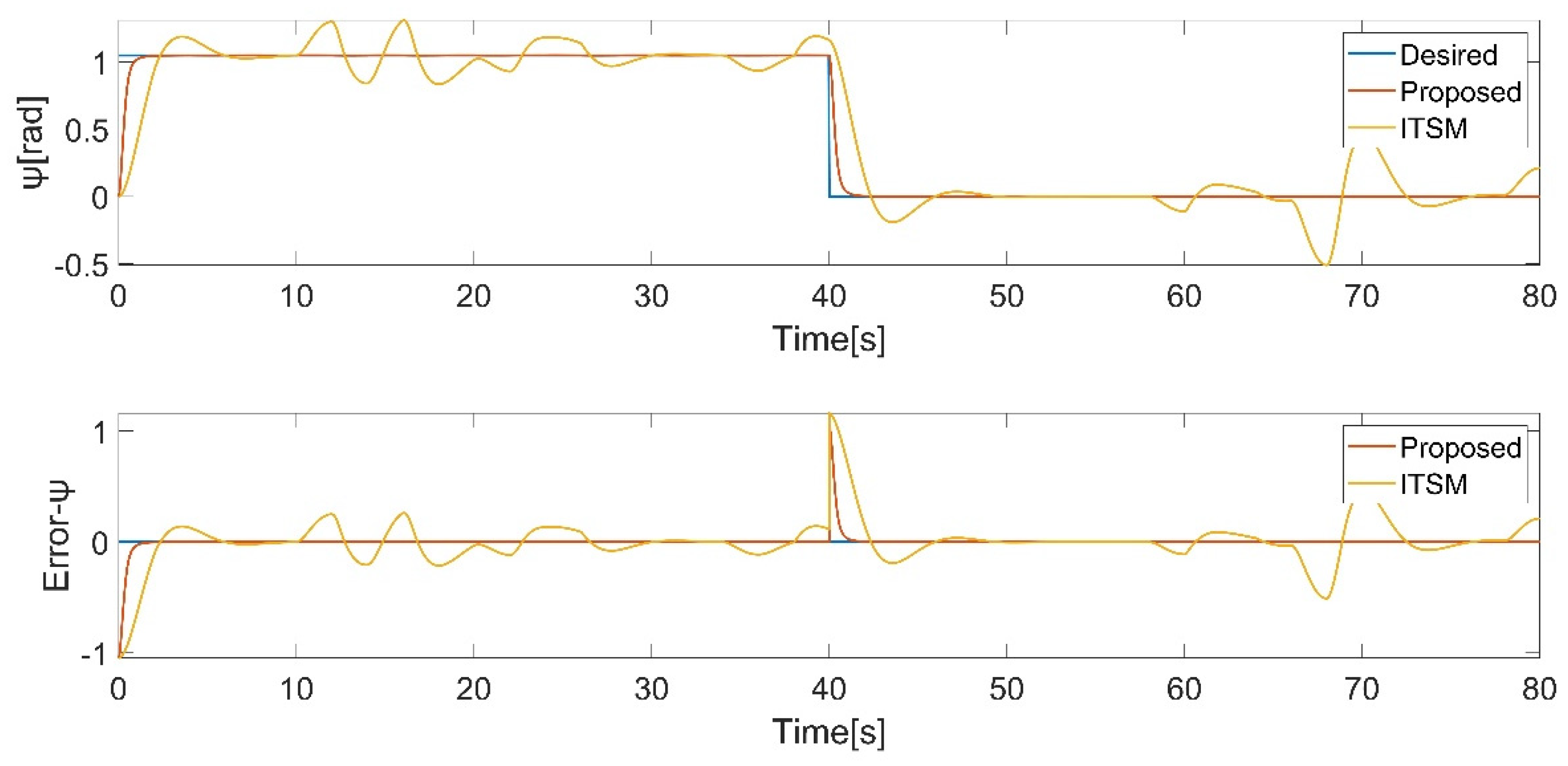
In this scenario, the quadrotor is required to track a sophisticated trajectory under the influence of external disturbances. The simulation results are presented in Figure 12-18.
The desired trajectories are defined as follows:
From
Figure 13,
Figure 14,
Figure 15,
Figure 16,
Figure 17 and
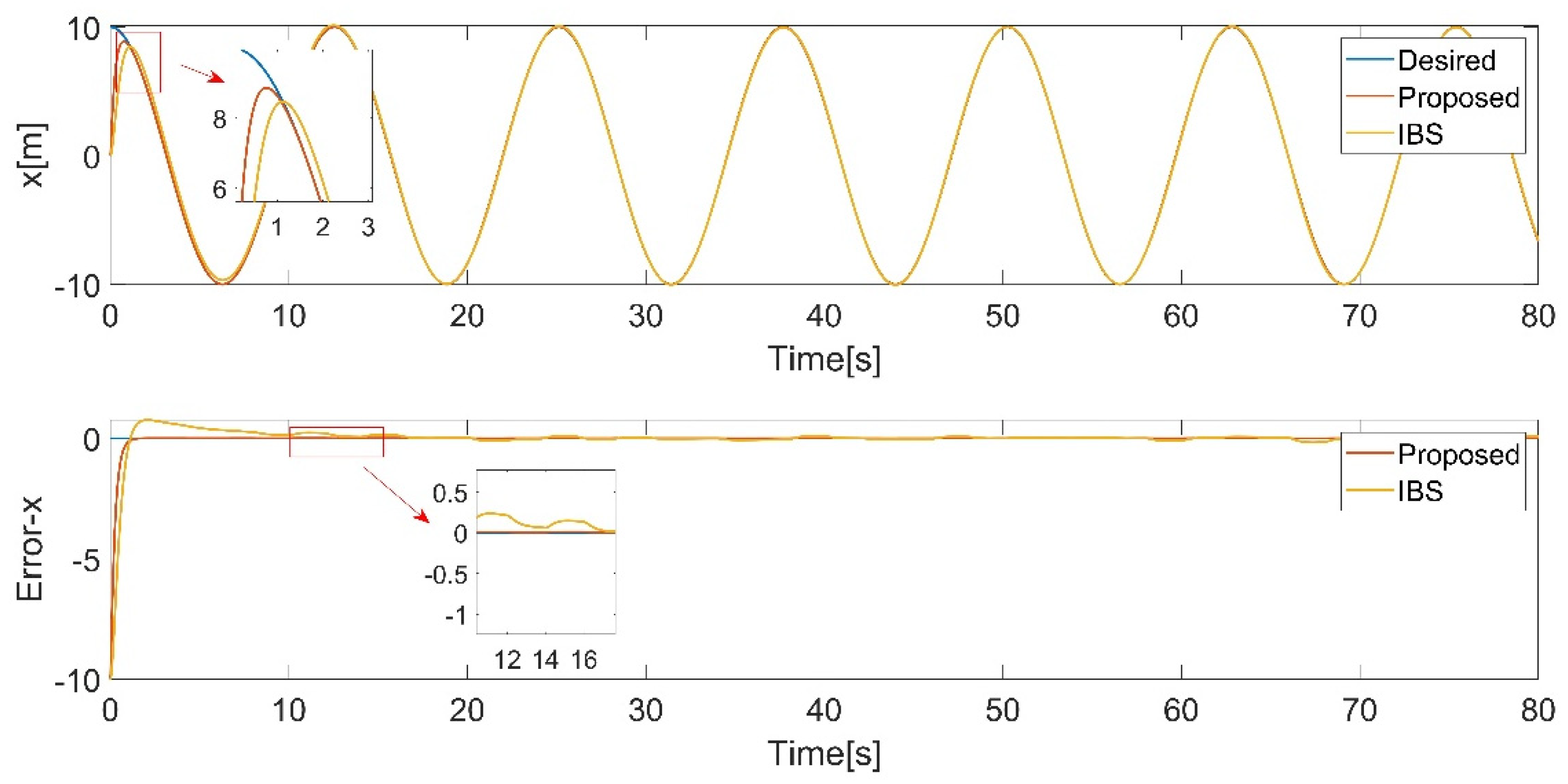
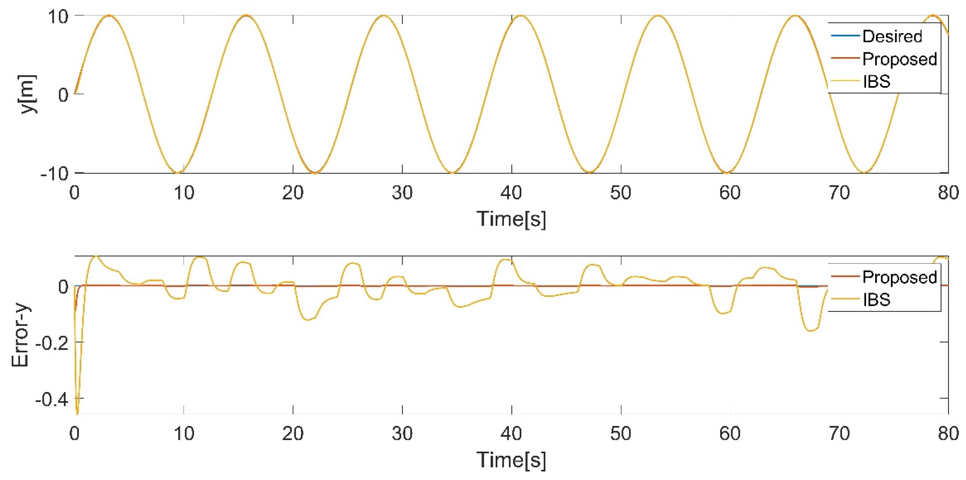
Figure 18, it can be observed that the tracking performance of the IBS-ITSM control is not ideal, exhibiting relatively large fluctuations in the presence of disturbances. In contrast, the proposed controller successfully tracked the desired trajectory and attitude faster and more accurately, demonstrating the robustness and superiority of the proposed controller.
Figure 12.
3D position trajectory tracking.
Figure 12.
3D position trajectory tracking.
5. Conclusion
In this paper, the quadrotor dynamic model considering parameter uncertainty and external disturbances is derived with the Newton-Euler equation. An AIBS control is proposed in position loop. The desired attitude is derived by decoupling equations based on the desired position. Furthermore, a new ABFNITSM control is proposed for the attitude tracking, utilizing integral element, backstepping, adaptive estimation technique and dead-zone technique based on terminal sliding mode control. A saturation function is introduced to eliminate chattering. The Lyapunov theory is employed to verify the stability of the control system. Finally, the proposed AIBS-ABFNITSM control has better performance and good robustness against external random disturbances through comparing it with IBS-ITSM.
6. Future work
Future work includes validating the performance of the AIBS-ABFNITSM control scheme in trajectory tracking tasks on an actual quadrotor. Considering the limitations of Euler angles, exploring the application of quaternions in quadrotor’s attitude trajectory tracking control is worth investigating.
Author Contributions
Conceptualization, Shipeng Jiao, Jun Wang and Yuchen Hua; Data curation, Shipeng Jiao; Formal analysis, Shipeng Jiao; Investigation, Shipeng Jiao; Methodology, Shipeng Jiao, Jun Wang and Yuchen Hua; Project administration, Ye Zhuang; Resources, Shipeng Jiao, Jun Wang and Yuchen Hua; Software, Shipeng Jiao; Supervision, Jun Wang, Yuchen Hua and Ye Zhuang; Validation, Shipeng Jiao; Visualization, Shipeng Jiao and Xuetian Yu; Writing – original draft, Shipeng Jiao; Writing – review & editing, Jun Wang, Yuchen Hua and Ye Zhuang. All authors have read and agreed to the published version of the manuscript.
Funding
This research received no external funding.
Data Availability Statement
The data is contained within the article.
Conflicts of Interest
The authors declare no conflicts of interest.
Appendix A
Appendix A.1. Assumptions
The quadrotor structure is symmetric.
The geometric center of the quadrotor coincides with its center of gravity.
The forces and torques caused by air friction are proportional to the quadrotor’s velocity and the square of the quadrotor’s angular velocity, respectively.
External disturbances enter the system in the form of acceleration.
The forces and moments generated by the motors are proportional to the square of the motor speeds.
References
- Liang, X.; Yu, H.; Zhang, Z.; Liu, H.; Fang, Y.; Han, J. Unmanned aerial transportation system with flexible connection between the quadrotor and the payload: modeling, controller design, and experimental validation. IEEE T. Ind. Electron. 2022, 70(2), 1870–1882. [Google Scholar] [CrossRef]
- Wang, Y.; Lu, Q.; Ren, B. Wind Turbine Crack Inspection Using a Quadrotor with Image Motion Blur Avoided. IEEE Robot. Autom. Lett. 2023, 8(2), 1069–1076. [Google Scholar] [CrossRef]
- Huang, T.; Huang, D.; Wang, Z.; Dai, X.; Shah, A. Generic adaptive sliding mode control for a quadrotor UAV system subject to severe parametric uncertainties and fully unknown external disturbance. Int. J. Control Autom. Syst. 2021, 19, 698–711. [Google Scholar] [CrossRef]
- Li, B.; Gong, W.; Yang, Y.; Xiao, B.; Ran, D. Appointed fixed time observer-based sliding mode control for a quadrotor UAV under external disturbances. IEEE T. Aero. Elec. Sys. 2021, 58(1), 290–303. [Google Scholar] [CrossRef]
- Pan, J.; Shao, B.; Xiong, J.; Zhang, Q. Attitude control of quadrotor UAVs based on adaptive sliding mode. Int. J. Control Autom. Syst. 2023, 1–10. [Google Scholar] [CrossRef]
- Pouzesh, M.; Mobayen, S. Event-triggered fractional-order sliding mode control technique for stabilization of disturbed quadrotor unmanned aerial vehicles. Aerosp. Sci. Technol. 2022, 121, 107337. [Google Scholar] [CrossRef]
- Sonugür, G. A Review of quadrotor UAV: Control and SLAM methodologies ranging from conventional to innovative approaches. Robot. Auton. Syst. 2023, 161, 104342. [Google Scholar] [CrossRef]
- Xiong, J.; Pan, J.; Chen, G.; Zhang, X.; Ding, F. Sliding mode dual-channel disturbance rejection attitude control for a quadrotor. IEEE T. Ind. Electron. 2021, 69(10), 10489–10499. [Google Scholar] [CrossRef]
- Labbadi, M.; Cherkaoui, M. Robust adaptive nonsingular fast terminal sliding-mode tracking control for an uncertain quadrotor UAV subjected to disturbances. ISA Trans. 2020, 99, 290–304. [Google Scholar] [CrossRef]
- Rojsiraphisal, T.; Mobayen, S.; Asad, J. H.; Vu, M. T.; Chang, A.; Puangmalai, J. Fast terminal sliding control of underactuated robotic systems based on disturbance observer with experimental validation. Mathematics 2021, 9(16), 1935. [Google Scholar] [CrossRef]
- Lim, D.; Kim, H.; Yee, K. Uncertainty propagation in flight performance of multirotor with parametric and model uncertainties. Aerosp. Sci. Technol. 2022, 122, 107398. [Google Scholar] [CrossRef]
- Kim, H.; Ahn, H.; Chung, Y.; You, K. Quadrotor Position and Attitude Tracking Using Advanced Second-Order Sliding Mode Control for Disturbance. Mathematics 2023, 11(23), 4786. [Google Scholar] [CrossRef]
- Li, Z.; Zhang, Y.; Wu, H.; Suzuki, S.; Namiki, A.; Wang, W. Design and Application of a UAV Autonomous Inspection System for High-Voltage Power Transmission Lines. Remote Sens. 2023, 15(3), 865. [Google Scholar] [CrossRef]
- Ha, Q. M.; Deville, Y.; Pham, Q. D.; Hà, M. H. On the min-cost traveling salesman problem with drone. Transp. Res. Part C Emerg. Technol. 2018, 86, 597–621. [Google Scholar] [CrossRef]
- Wang, C.; Liu, Y.; Zhang, Z.; Han, L.; Li, Y.; Zhang, H.; Wongsuk, S.; Wu, X.; He, X. Spray performance evaluation of a six-rotor unmanned aerial vehicle sprayer for pesticide application using an orchard operation mode in apple orchards. Pest Manag. Sci. 2022, 78(6), 2449–2466. [Google Scholar] [CrossRef]
- Nair, A. P.; Selvaganesan, N.; Lalithambika, V. R. Lyapunov based PD/PID in model reference adaptive control for satellite launch vehicle systems. Aerosp. Sci. Technol. 2016, 51, 70–77. [Google Scholar] [CrossRef]
- Zhengxi, W; Yang, C; Xiujuan, Z; Lei, C. Quadrotor UAV Control with Disturbance Based on Aerodynamic Parameter Estimation. Inf. Control 2018, 47(6), 663–670.
- Li, C.; Wang, Y.; Yang, X. Adaptive fuzzy control of a quadrotor using disturbance observer. Aerosp. Sci. Technol. 2022, 128, 107784. [Google Scholar] [CrossRef]
- Guettal, L.; Chelihi, A.; Ajgou, R.; Touba, M. M. Robust tracking control for quadrotor with unknown nonlinear dynamics using adaptive neural network based fractional-order backstepping control. J. Franklin Inst. 2022, 359(14), 7337–7364. [Google Scholar] [CrossRef]
- Yu, S.; Yu, X.; Shirinzadeh, B.; Man, Z. Continuous finite-time control for robotic manipulators with terminal sliding mode. Automatica 2005, 41(11), 1957–1964. [Google Scholar] [CrossRef]
- Shao, K.; Zheng, J.; Huang, K.; Wang, H.; Man, Z.; Fu, M. Finite-time control of a linear motor positioner using adaptive recursive terminal sliding mode. IEEE T. Ind. Electron. 2019, 67(8), 6659–6668. [Google Scholar] [CrossRef]
- Cui, R.; Chen, L.; Yang, C.; Chen, M. Extended state observer-based integral sliding mode control for an underwater robot with unknown disturbances and uncertain nonlinearities. IEEE T. Ind. Electron. 2017, 64(8), 6785–6795. [Google Scholar] [CrossRef]
- Labbadi, M.; Muñoz-Vázquez, A. J.; Djemai, M.; Boukal, Y.; Zerrougui, M.; Cherkaoui, M. Fractional-order nonsingular terminal sliding mode controller for a quadrotor with disturbances. Appl. Math. Model. 2022, 111, 753–776. [Google Scholar] [CrossRef]
- Lian, S.; Meng, W.; Shao, K.; Zheng, J.; Zhu, S.; Li, H. Full Attitude Control of a Quadrotor Using Fast Nonsingular Terminal Sliding Mode With Angular Velocity Planning. IEEE T. Ind. Electron. 2022, 70(4), 3975–3984. [Google Scholar] [CrossRef]
- Labbadi, M.; Cherkaoui, M. Robust adaptive nonsingular fast terminal sliding-mode tracking control for an uncertain quadrotor UAV subjected to disturbances. ISA Trans. 2020, 99, 290–304. [Google Scholar] [CrossRef] [PubMed]
- Ebrahimi, N.; Ozgoli, S.; Ramezani, A. Model-free high-order terminal sliding mode controller for Lipschitz nonlinear systems. Implemented on Exoped® exoskeleton robot. Int. J. Syst. Sci. 2021; 52, 1061–1073. [Google Scholar] [CrossRef]
- Abaunza, H.; Castillo, P. Quadrotor aggressive deployment, using a quaternion-based spherical chattering-free sliding-mode controller. IEEE T. Aero. Elec. Sys. 2019, 56(3), 1979–1991. [Google Scholar] [CrossRef]
- Mofid, O.; Mobayen, S.; Zhang, C.; Esakki, B. Desired tracking of delayed quadrotor UAV under model uncertainty and wind disturbance using adaptive super-twisting terminal sliding mode control. ISA Trans. 2022, 123, 455–471. [Google Scholar] [CrossRef]
- Ghadiri, H.; Emami, M.; Khodadadi, H. Adaptive super-twisting non-singular terminal sliding mode control for tracking of quadrotor with bounded disturbances. Aerosp. Sci. and Technol. 2021, 112, 106616. [Google Scholar] [CrossRef]
- Huang, S.; Yang, Y. Adaptive neural-network-based nonsingular fast terminal sliding mode control for a quadrotor with dynamic uncertainty. Drones 2022, 6(8), 206. [Google Scholar] [CrossRef]
- Mo, H.; Farid, G. Nonlinear and adaptive intelligent control techniques for quadrotor uav–a survey. Asian J. Control 2019, 21(2), 989–1008. [Google Scholar] [CrossRef]
|
Disclaimer/Publisher’s Note: The statements, opinions and data contained in all publications are solely those of the individual author(s) and contributor(s) and not of MDPI and/or the editor(s). MDPI and/or the editor(s) disclaim responsibility for any injury to people or property resulting from any ideas, methods, instructions or products referred to in the content. |
© 2024 by the authors. Licensee MDPI, Basel, Switzerland. This article is an open access article distributed under the terms and conditions of the Creative Commons Attribution (CC BY) license (http://creativecommons.org/licenses/by/4.0/).

