1. Introduction
The finite element method (FEM) has become a conventional procedure for evaluating the structural performance of automobiles through computer simulation, and it is widely utilized in the industrial field as commercial software. While computer-aided design (CAD) is used to manage the shape of automobile structures, recently, the inconsistency in data between CAD and FEM, such as shape reproducibility and design changes, has become a drawback.
Isogeometric analysis (IsoGeometric Analysis: IGA) [
1,
2] has been proposed as an alternative analysis method to FEM with the aim of enhancing the compatibility of data used in CAD and analysis, and it is garnering significant attention. The main difference between IGA and FEM lies in the choice of basis functions used to interpolate the internal quantities from the points where the physical quantities are defined. Since the basis functions of IGA use the same spline functions as CAD, their data is compatible. Structural analysis by IGA has already been extensively studied, and research on complicated curved surface structures by trimming and connecting has also been reported [
3,
4,
5]. IGA is also applied in the medical field, such as analyzing blood flow in the heart and blood vessels through fluid-structure interaction analysis [
6].
In this study, we conducted a fundamental investigation into the applicability of IGA for analyzing structural deformations and automobile crashes. Recently, IGA has been implemented in commercial software, and its functions have reached a practical level [
7,
8]. IGA has also been introduced to the explicit dynamic method used in automobile crash analysis [
9]. For automobile crash analysis, consistency is essential not only in the deformation state but also in the actual phenomena, such as acceleration, velocity, and load, in time series. In the aforementioned context, a bending and buckling analysis of structural members is first conducted using IGA, and its applicability is investigated by comparing the results with experiments and FEM. Furthermore, IGA is applied to the crash analysis of the automobile body and its validity is confirmed.
2. Isogeometric Analysis
In this section, we provide an overview of IGA, outlining its features using figures and equations. Interested readers may refer to the literature [
1,
2] for more details on IGA. While IGA shares many common properties with FEM, the major distinguishing feature is the use of different basis functions. B-spline basis functions are used in IGA. In the B-spline basis function, the curved surface can be accurately reproduced because continuity is maintained on the mesh boundary. Additionally, in IGA, the analysis data can be flexibly improved by corresponding shape changes without the need for CAD [
10,
11,
12,
13].
2.1. B-spline function
The blue line in
Figure 1 shows the 2nd-order B-spline curve. A B-spline curve is composed of a linear combination of B-spline basis functions. The red points are control points and correspond to nodes in the FEM.
The B-spline basis function
N is defined recursively using the Cox-de Boor recurrence relation [
1], as shown in equations (
1) and (
2).
Here,
represents a knot. Additionally,
i represents a control point number, while
p denotes a order of the B-spline function.
As shown in
Figure 1, B-spline curves are not guaranteed to pass through control points, and in general, they do not. This means that the control points are not on the model in IGA, unlike in FEM. The B-spline curve
is represented by equation (
3).
Where,
represents the coordinates of the control points.
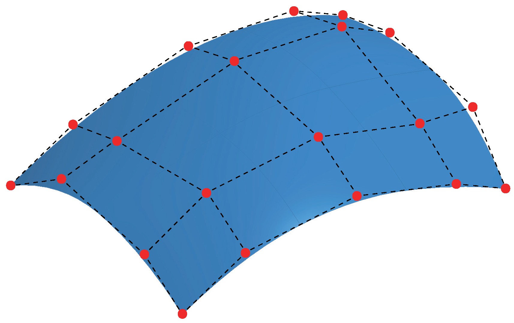
For the modeling of a shell, a B-spline surface is defined as shown in
Figure 2 using the superposition of B-spline functions. To model a three-dimensional solid, the shape is defined by superimposing three B-spline functions.
2.2. NURBS basis function
In the IGA modeling using the B-spline basis functions described above, there are geometric shapes that cannot be described, such as perfect circles and spheres. To eliminate this disadvantage, Non-Uniform Rational B-Spline (NURBS) basis functions were developed [
14]. The NURBS basis is an extension of the concept of the B-spline basis. In the NURBS basis function, by adjusting the weights of the control points as shown in
Figure 3, it is possible to model any geometrical shape by controlling the curvature of the curve near the control points.
The NURBS basis functions
R are represented by equations (
4), (
5), and (
6). The NURBS basis function for curve is defined as shown in equation (
4).
Also, the NURBS basis function for surface is given by equation (
5).
And the NURBS basis for function for solid is given by equation (
6).
Here,
and
are knots similar to
. Additionally,
M and
L are B-spline basis functions similar to
N, and
q and
r are orders of B-spline functions similar to
p.
2.3. Coordinate transformation by mapping
In both FEM and IGA, basis functions are used in a coordinate space different from the global coordinate system in which the analyst evaluates various physical quantities. In FEM, since the basis functions are defined within the local coordinate system, each quantity is mapped to the global coordinate system once. On the other hand, in IGA, the B-spline/NURBS basis functions and the local coordinate system are mapped to the global coordinate system by two mappings [
2].
3. Deformation Analysis of Structural Members
Three-point bending of the trailing arm and compression analysis of aluminum extrusions are computed using IGA. The performance of IGA in bending and buckling behavior is evaluated by comparing the results with experiments and FEM.
3.1. Three-point bending analysis of trailing arm
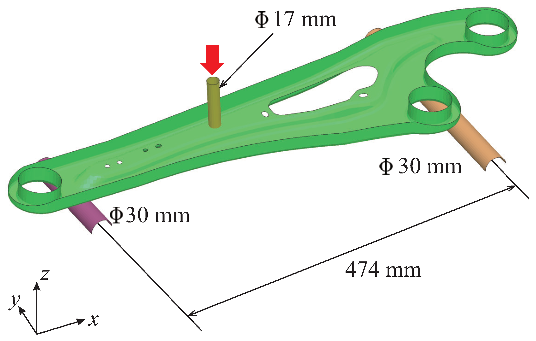
Figure 4 depicts the trailing arm, which is discussed here. The distance between the supports is 474 mm, and each support has a cross-sectional shape of a semicircle with a diameter of 30 mm. The cross-sectional shape of an indenter is a cylinder with a diameter of 17 mm. Then, the center of the member is compressed vertically downward with the indenter at 50 mm/min in the experiment. The thickness of the trailing arm is 2.3 mm.
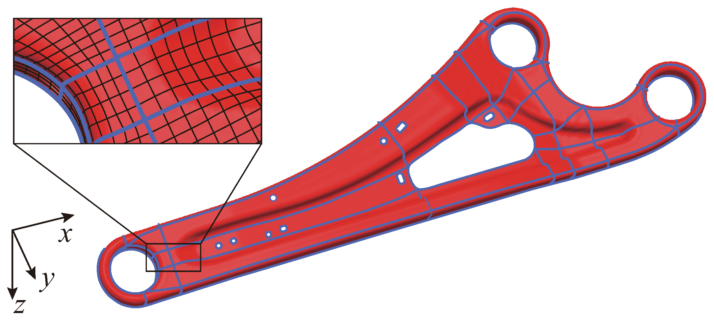
Figure 5 depicts the IGA model for the shell of the trailing arm. In the figure, the blue lines represent the boundaries of NURBS patches. These patches are created by combining multiple cubic NURBS patches, and small holes are accurately represented through trimming. Adjacent NURBS patches are connected by sharing control points. In the enlarged view in the
Figure 5, the black line represents the boundary of the subregion. A subregion in the IGA corresponds to an element in the FEM, and numerical integration is performed within this subregion.
Let the in-plane integration point be 3x3 within the subregion, with a pitch interval of 5mm. The FEM model for comparison is a 5mm-sized first-order shell element with in-plane fully numerical integration. The number of integration points in the thickness direction is 5 for both IGA and FEM. In both IGA and FEM calculations, the indenter speed is set to 5,000 mm/min, which is 100 times the experimental value, to enhance calculation efficiency by increasing the time increment in the explicit dynamic method. The material of the trailing arm is elastoplastic, and the material constants are mass density of 7,860 kg/m
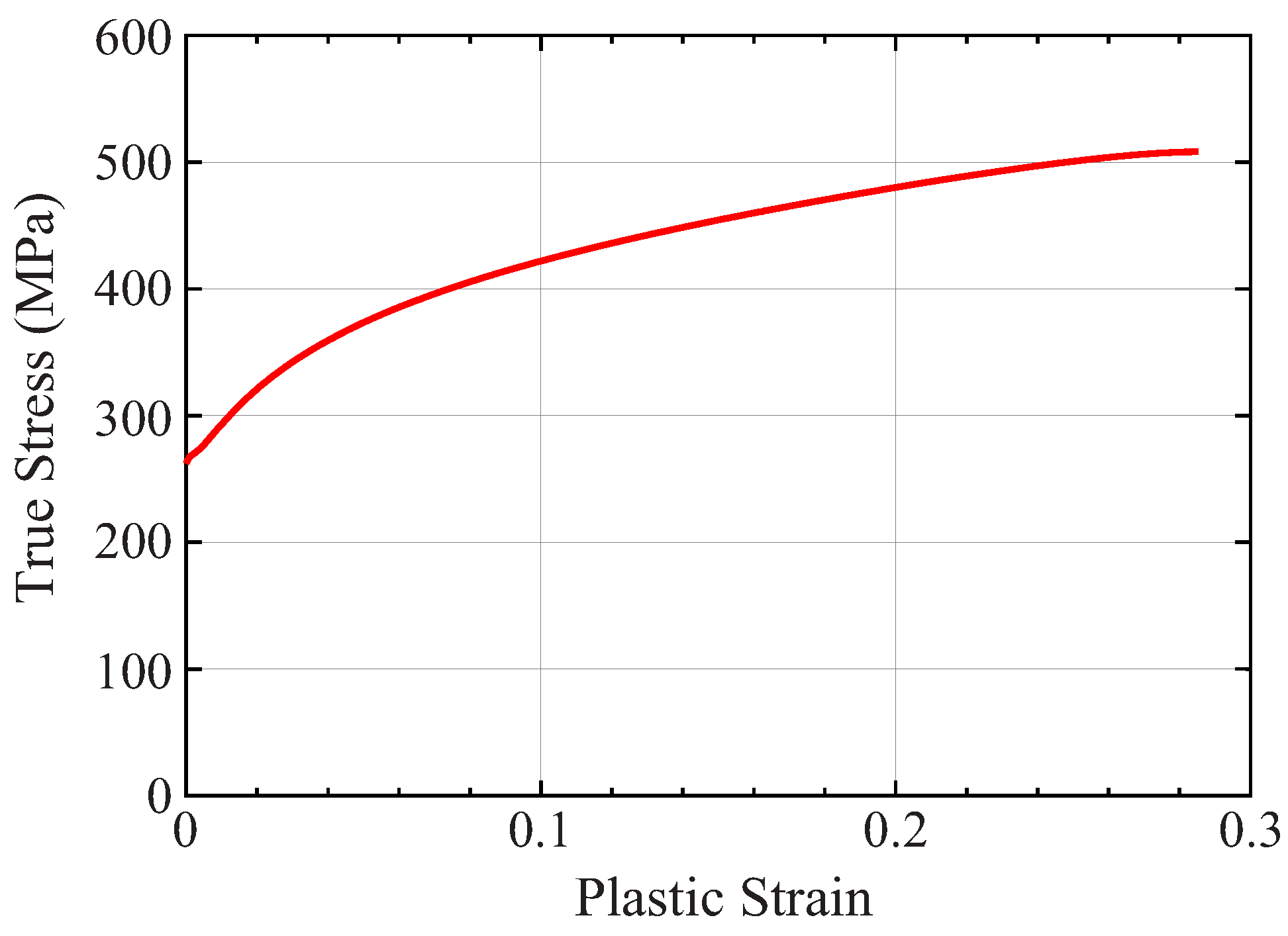
3, Young’s modulus of 206 GPa, and Poisson’s ratio of 0.3. The true stress-equivalent plastic strain relationship is set as shown in
Figure 6. The indenter and support are rigid bodies.
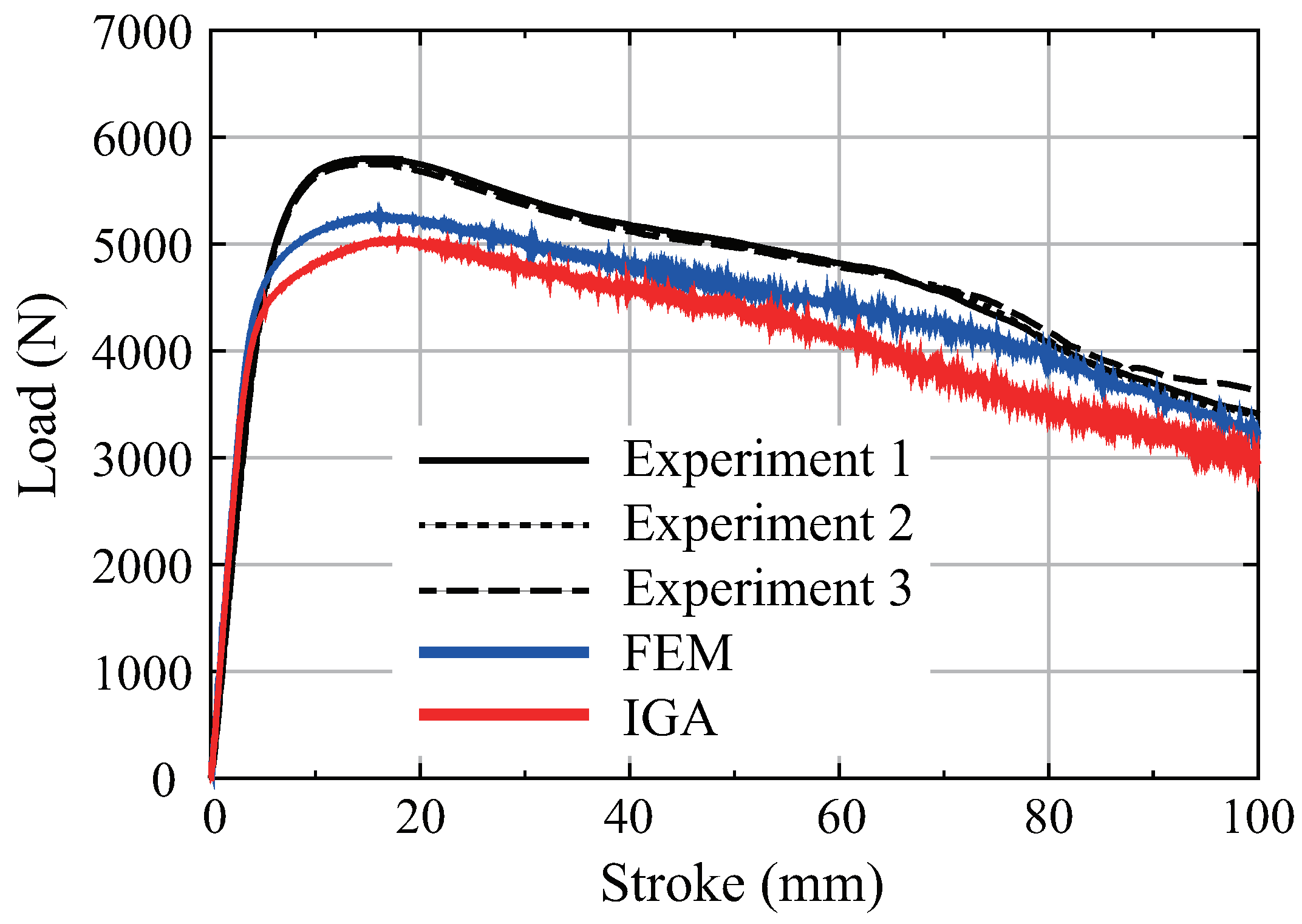
Figure 7 compares the load-stroke curves at the indentation point obtained from three experiments with the FEM and IGA analyses. In both FEM and IGA, the load-stroke curves are qualitatively consistent with the experimental results. However, in both cases, the load peak is lower than in the experiments. This is because the trailing arm includes changes in plate thickness and work hardening during forming in the experiment. On the other hand, these forming histories are not considered in the analysis. The load-stroke curve of IGA is slightly lower than that of FEM because IGA uses higher-order basis functions.
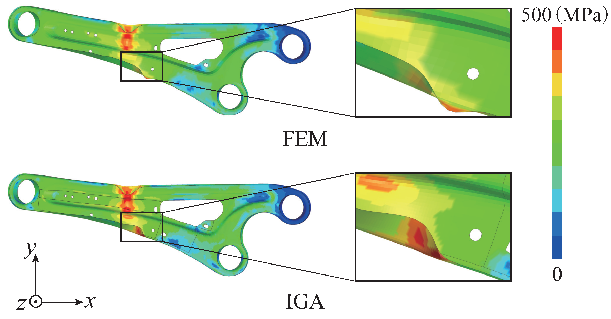
Figure 8 displays the deformation and a contour of the Mises stress for the trailing arm. The similar stress distribution as FEM can be obtained in IGA. In contrast to this, a distinct deformation is observed at the bottom center of the enlarged model. One reason is for this is that this is an location where consistent deformation cannot be achieved even in multiple experiments.
3.2. Compression analysis of aluminum extrusions
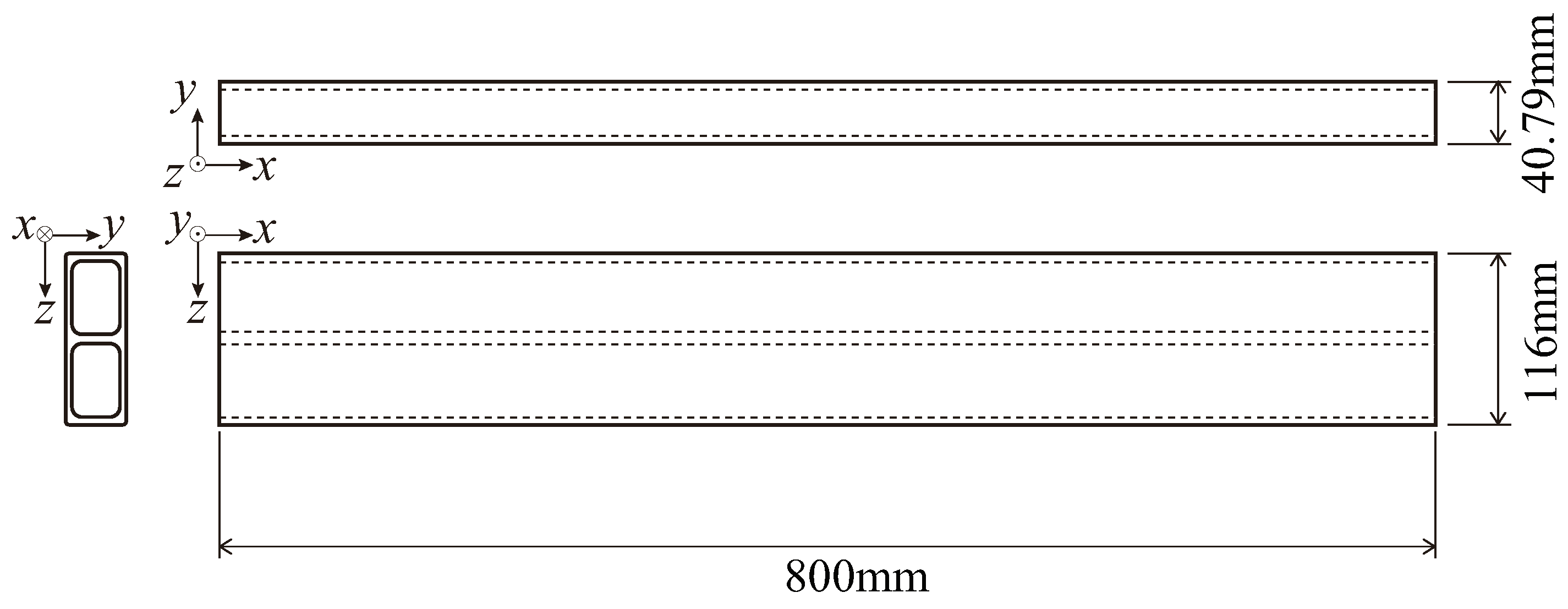
Figure 9 shows the dimensions of aluminum extrusions based on actual measurements.
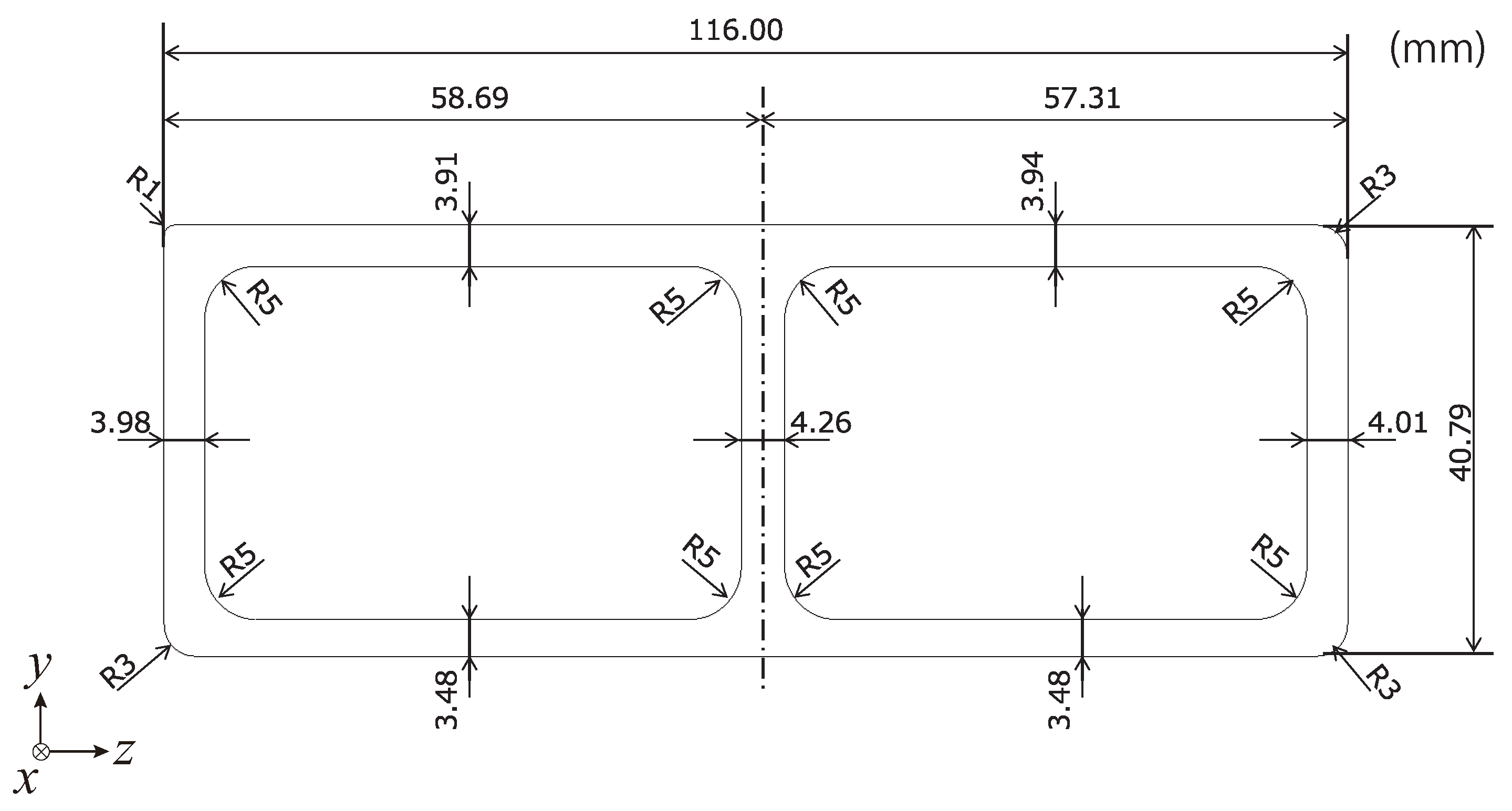
Figure 10 is its cross-sectional dimension, with two cavities. Compression analysis is conducted using an aluminum extrusion with this cross-section to evaluate the performance of IGA in buckling deformation.
A model of a thick plate such as an aluminum extrusion is treated. A solid model is employed instead of the shell to obtain sufficient accuracy for the bending of members.
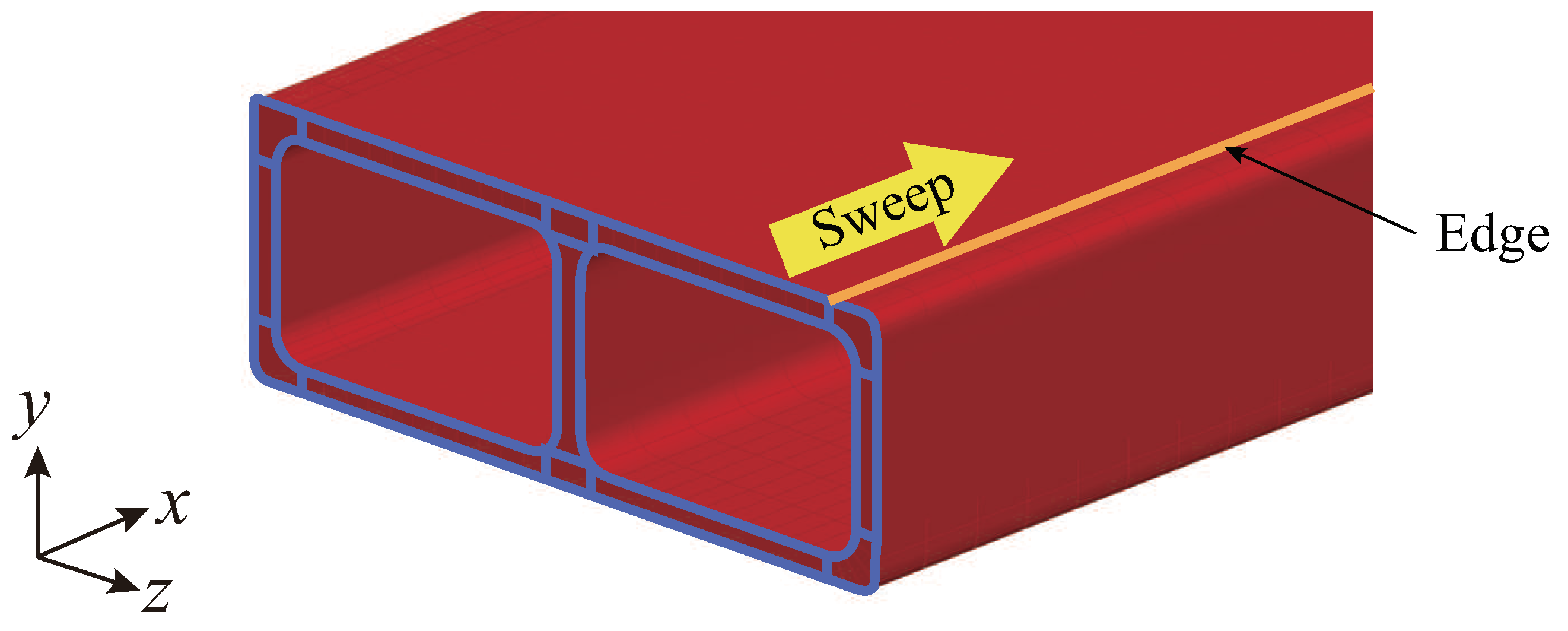
Figure 11 depicts the aluminum extrusion model created using NURBS solids. The blue line in the figure represents the boundary of the NURBS patch on the model section, and the extruded model is generated by sweeping along the yellow edge.
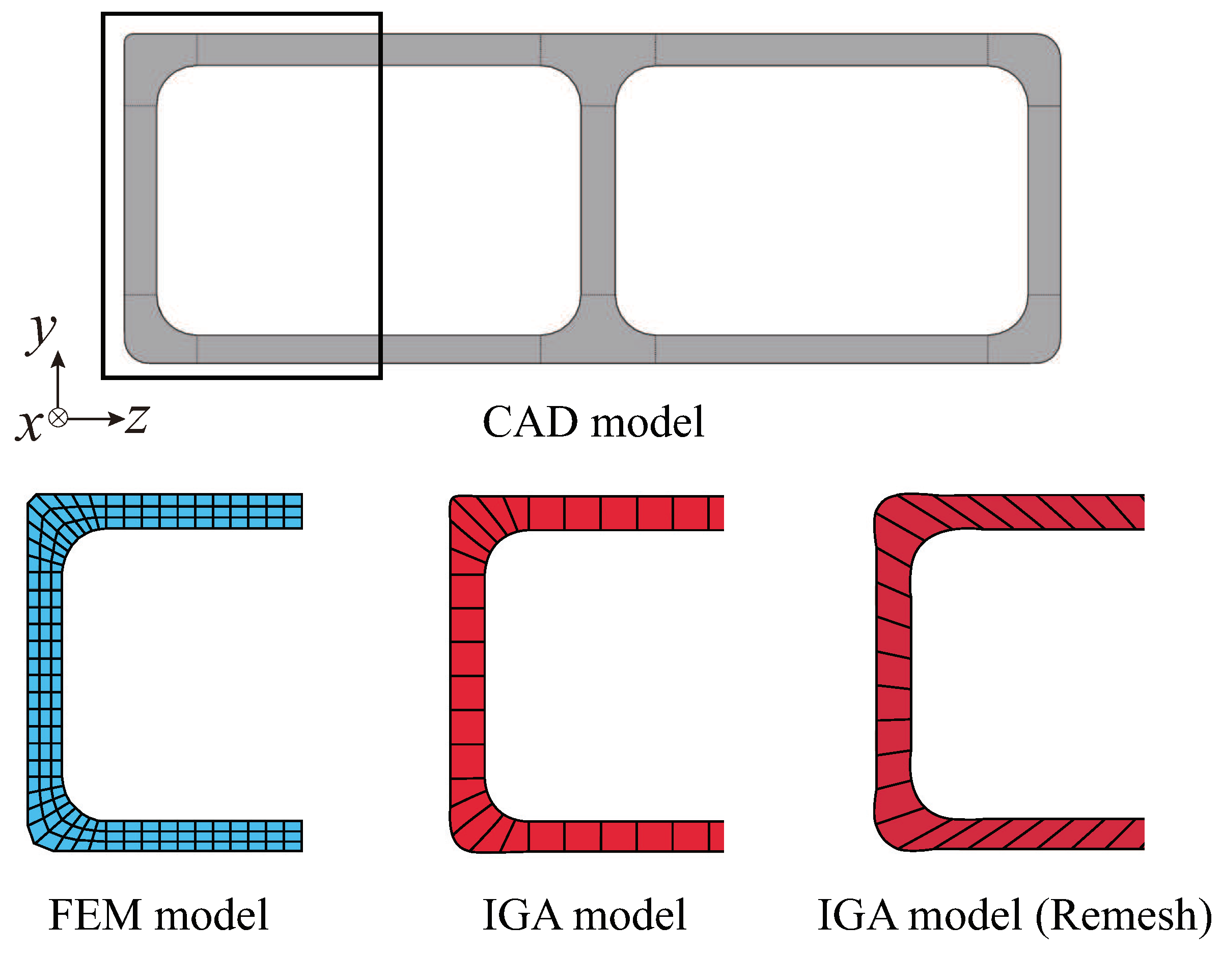
Figure 12 shows the element division by FEM and the subregion by IGA in the cross section. In FEM, 1-point and selective reduced integration are used with 8-node 3D solid elements. The cubic-order NURBS solids are used in IGA. In addition, in the normal IGA model, control points are crowded at the corners of the cross section. To prevent a decrease in the time increment in the explicit dynamic method caused by the crowded control points, a remesh model is also created, similar to the IGA model (Remesh) shown in
Figure 12. However, in the remeshed model, the poor reproducibility of the cross-sectional shape is observed by widening of the control point interval.
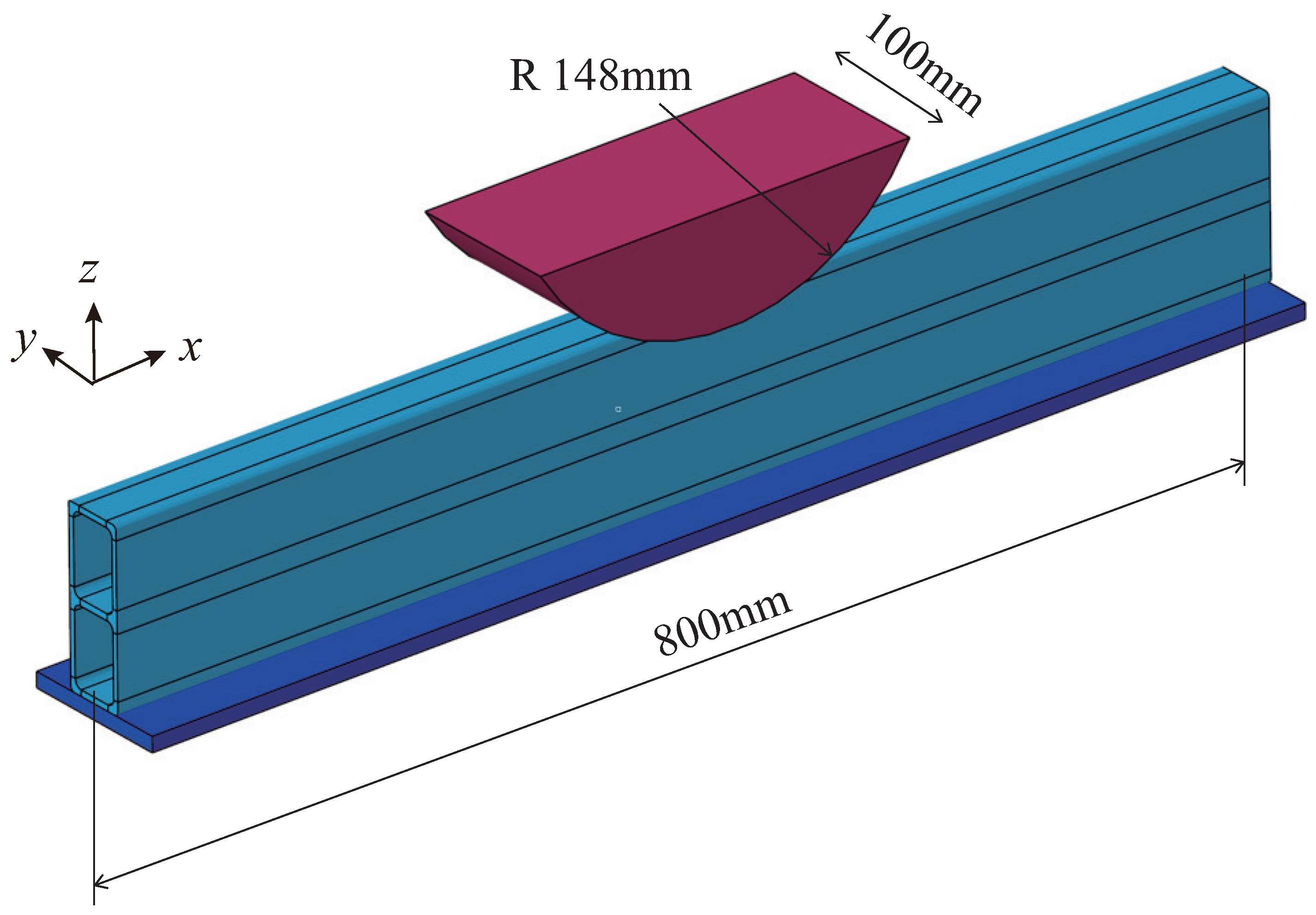
Figure 13 shows the compression analysis conditions. The aluminum extruded member is stood cross-sectional upright on a flat plate, and the center of the member is compressed vertically downward with an indenter with a radius of 148 mm and a width of 100 mm. Although the indenter speed is 50 mm/min in the experiments, the indenter speed is adjusted to 500 mm/sec in the analysis to enhance the calculation efficiency of the explicit dynamic method. Where, the aluminum extruded member is an elastic-plastic material with a mass density of 2,740 kg/m
3, a Young’s modulus of 68.95 GPa, and a Poisson’s ratio of 0.33.
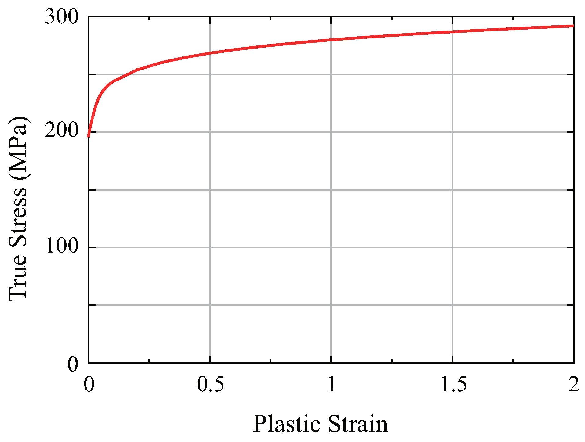
Figure 14 shows the true stress-equivalent plastic strain relationship of aluminum extrusions. Here, the plate and the indenter are assumed to be rigid bodies. In this analysis, fracture is not introduced.
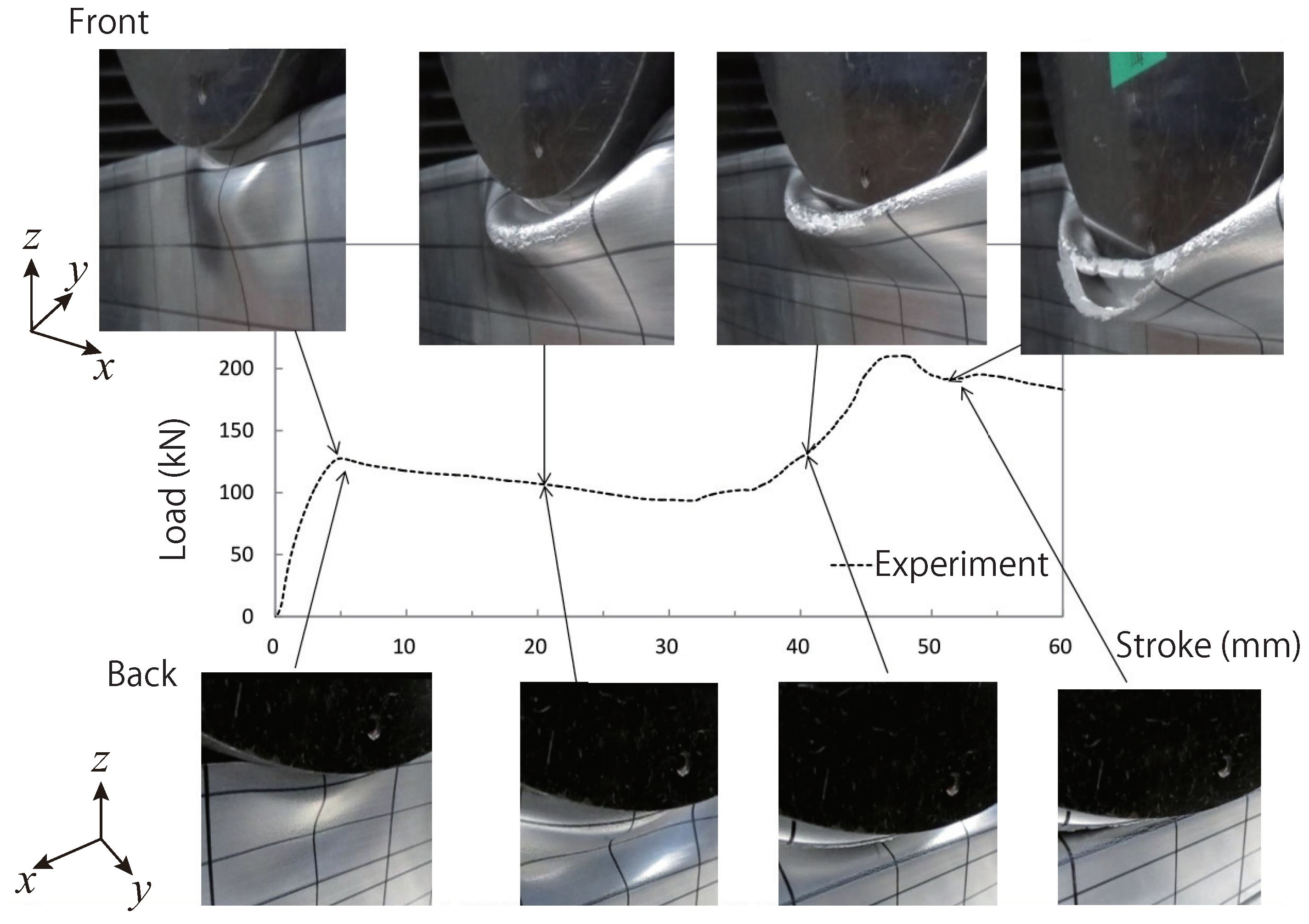
Figure 15 shows the load-stroke curve obtained from the experiment, and deformation state of the structure. The load initially increases and then decreases as the upper part of the structure starts to buckle. When the deformation of the lower part of the structure begins, the load increases once more, and then the load decreases due to the buckling of the lower part of the structure.
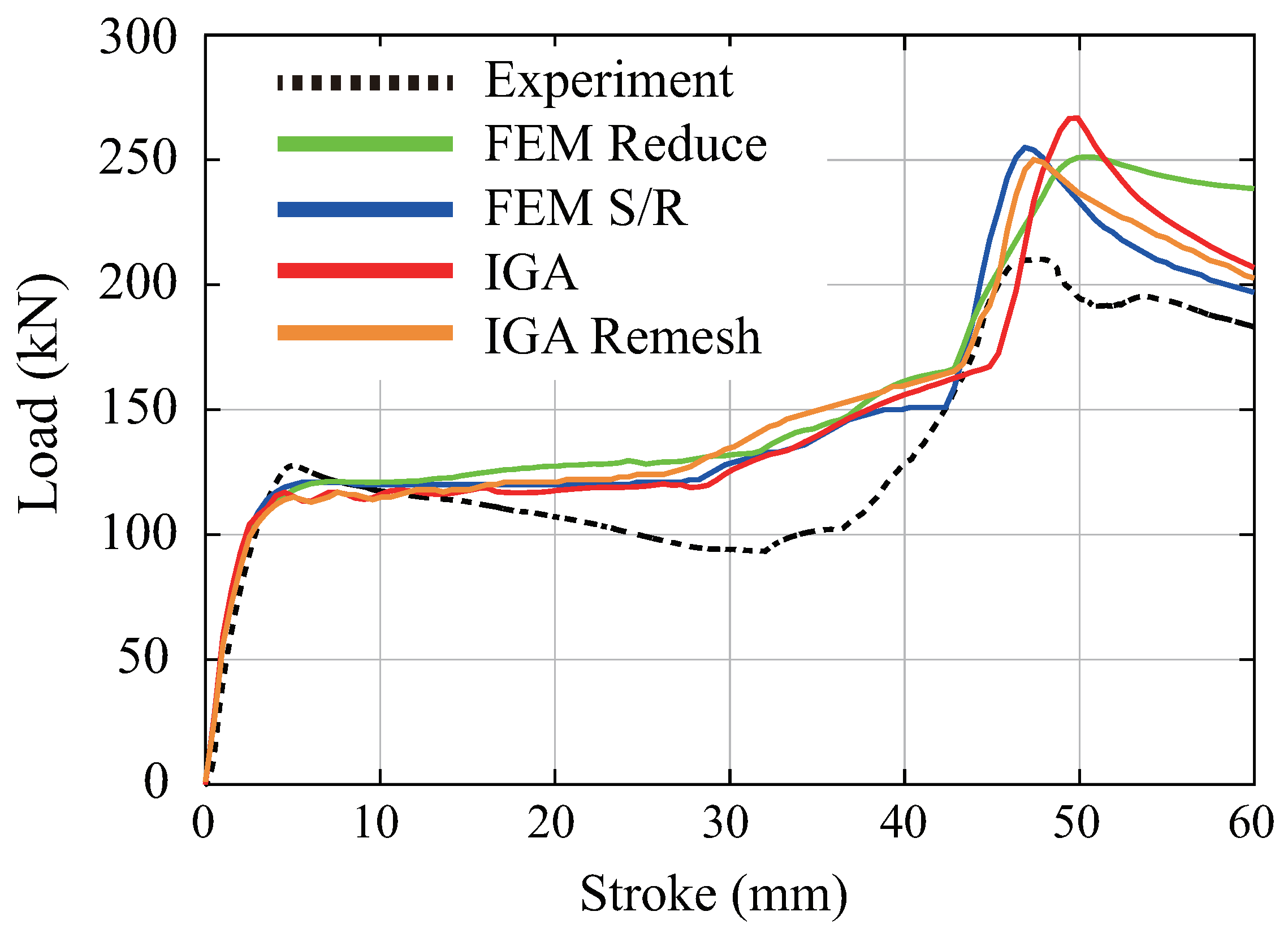
Figure 16 is the load-stroke curves of the indenter obtained from this analysis and the experiment. Where FEM Reduce and FEM S/R denote one-point integration and selective reduced integration of 8-node 3D solid elements in FEM, respectively. All FEMs and IGAs exhibit strong agreement with the experimental results in the initial slopes. However, after that, although the load decreased and then increased again in the experiment, the load increased again without decreasing in the analysis. This is because the fracture criterion is not considered in the present analysis.
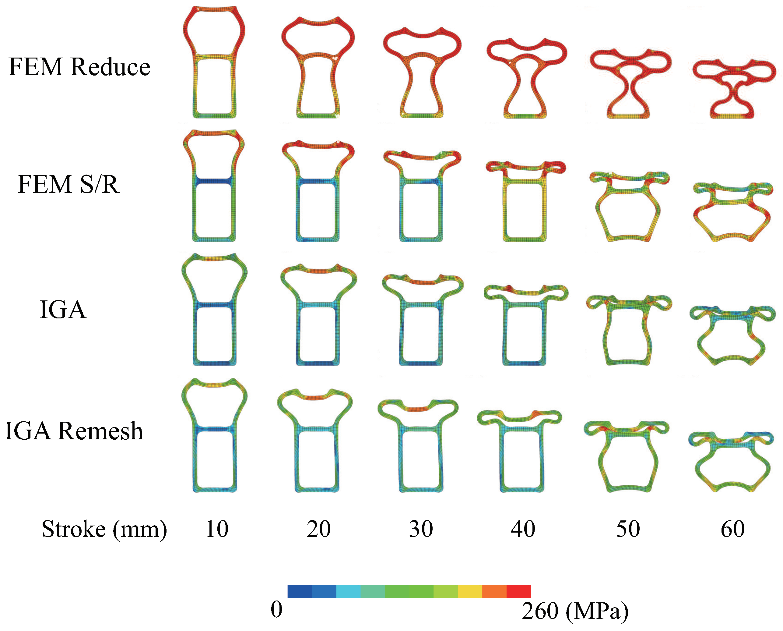
Figure 17 shows the deformation and Mises stress distribution of the central cross section of the member at various stroke levels. For the 8-node 3D solid elements used in FEM, selective reduced integration (FEM S/R) is generally known to provide greater accuracy than one-point integration (FEM Reduce). In
Figure 17, the buckling mode of IGA is the same as that of selective reduced integration of FEM (FEM S/R). This result indicates the high performance of IGA. In the experiment, a buckling mode in which the unevenness is reversed on the front and back of the cross section is observed. On the other hand, in this analysis, we cannot reproduce this buckling mode because the introduction of fracture conditions is insufficient.
The fracture of IGA can be evaluated by eliminating each subregion in the same way as eliminating elements in FEM, but determining the fracture condition while considering the differences in each size is indispensable.
4. Crash Analysis of Automobile
In this section, IGA is applied to the crash analysis of the automobile body. In the deformation analysis of structural members mentioned above, computational results were compared with experimental data. In this analysis, the validity of IGA in automobile crash analysis is examined by comparing it with the analysis results of FEM.
4.1. Automobile body model
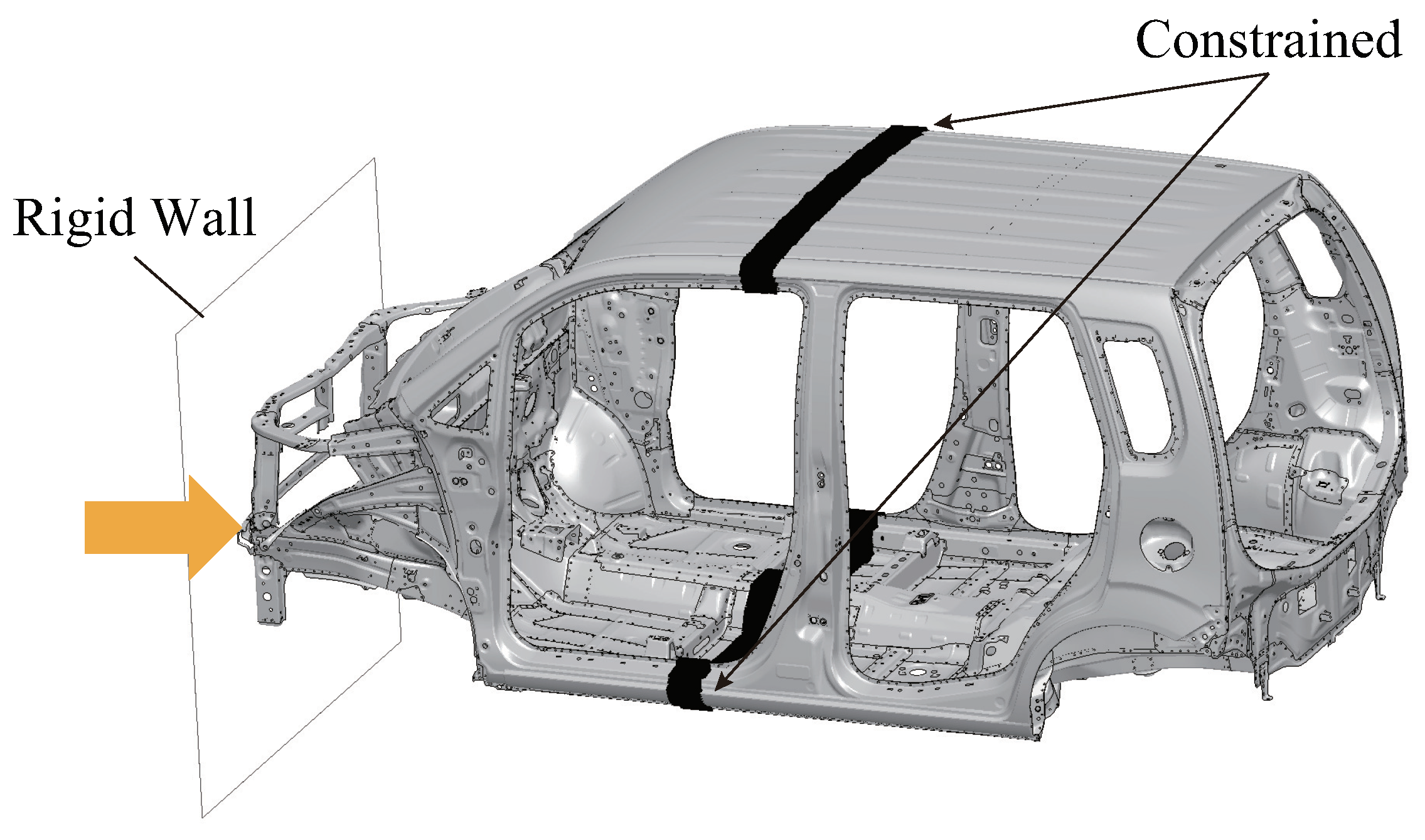
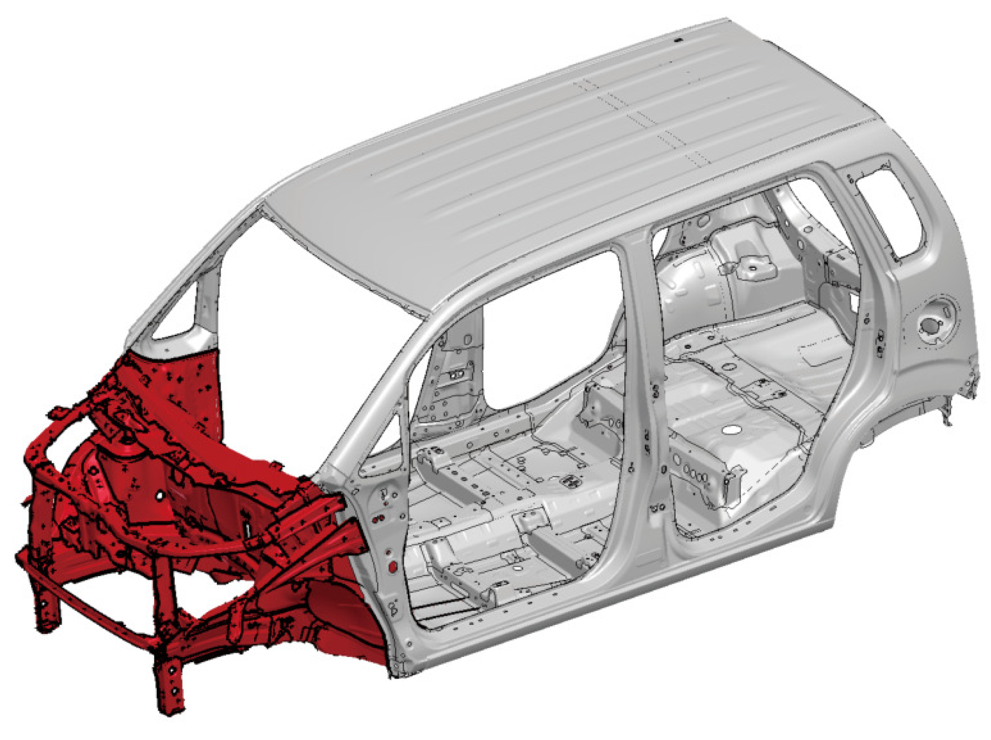
Figure 18 is the computational automobile body model. This model consists of 367 components and 2,000 spot-welded points. In the spot welding locations, nodes of beams are connected using free nodes within a patch, similar to FEM, without considering fractures. At the front of the B-pillar, nodes are fully constrained, and the automobile body is subjected to impact due to the rigid wall’s displacement from the front of the automobile. The velocity of the rigid wall is 18 km/h. Here, only the front part of the automobile body, which mainly affects the analysis results, is modeled using IGA, and the region beyond that is modeled using FEM.
Figure 19 represents an analysis model that combines IGA and FEM. The 114 components in the red area are modeled using IGA shells, while the gray area is modeled using FEM shells. The IGA regions are divided into subdomains of sizes 5mm and 10mm, while the FEM regions are divided into elements of a uniform size of 5mm. Furthermore, for the IGA subdomains and FEM elements, the same order and number of integration points, as validated in the previous section on the three-point bending analysis of the trailing arm in section 3.1, are employed.
4.2. Computational results
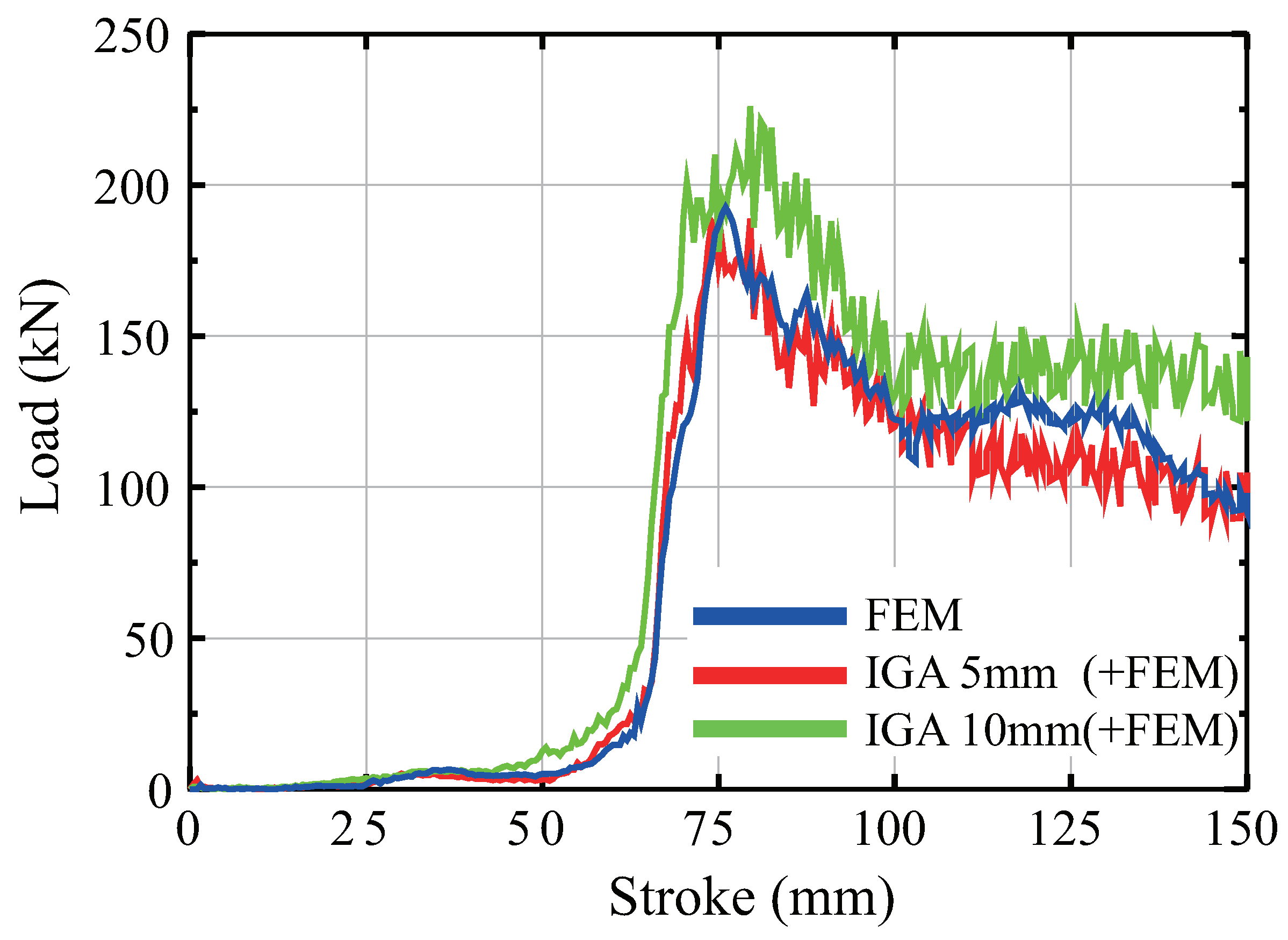
Figure 20 depicts the load-stroke curves for the rigid wall in each of the respective models. The results obtained from the IGA model with a 5mm subdomain size closely correspond to the reference results from the FEM analysis. In contrast, the results from the IGA model with a 10mm subdomain size indicate an increase in strength.
The deformation states will be considered next.
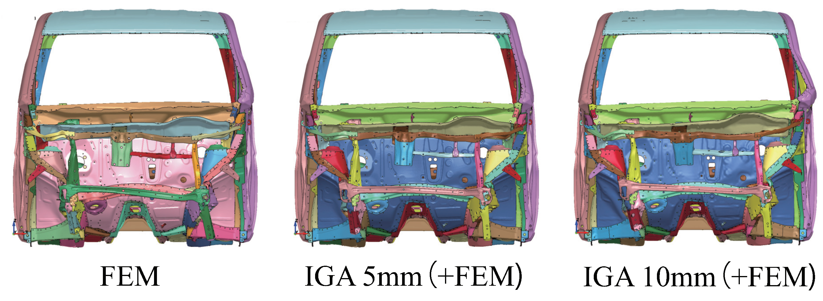
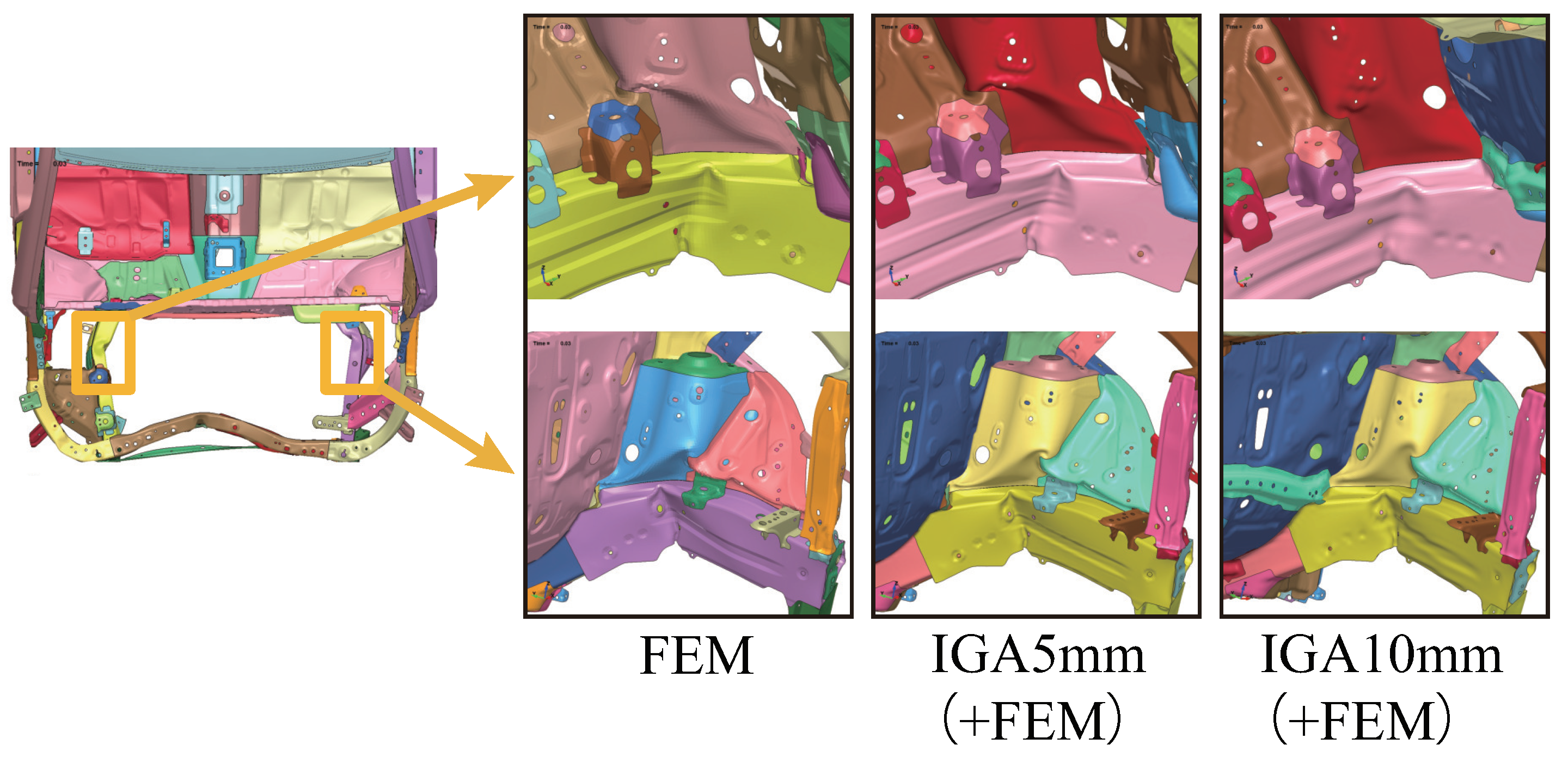
Figure 21 and
Figure 22 show deformation views from the front and top of the automobile, respectively. The deformation of the IGA model with a 5mm subdomain size is highly consistent with the deformation states observed in the FEM analysis. In comparing the deformation of the IGA model with a 10mm subdomain size to the FEM model, it is observed that the locations of buckling are nearly identical, but the deformation tends to be small.
In the IGA model with a 10mm subdomain size, a significant difference from the others is the occurrence of localized buckling in the A-pillar on the left side of the automobile, as shown in the right image in
Figure 21.
4.3. Computational time
The computational time for each model is presented in
Table 1. In parallel computation with 16 domain partitions, uniform time increments are used for all analyses employing mass scaling of the explicit dynamic method. As evident from this table, the IGA model with a 5mm domain exhibits approximately double the computational time compared to the FEM, while the IGA model with a 10mm domain results in nearly equivalent computation times.
5. Conclusions
To verify the applicability of IGA to automobile crash analysis, performance evaluations of bending and buckling deformations of structural components have been conducted using the explicit dynamic method. Furthermore, IGA was applied to the crash analysis of automobile body. Through these investigations, it has been confirmed that structural analysis with IGA using the explicit dynamic method provides analysis accuracy and computational efficiency comparable to FEM, while also being highly practical.
One future challenge is to enhance shape representation accuracy by improving modeling adjusted to weight functions in IGA. Furthermore, quantitative consistency with experiments will be improved through the examination of fracture conditions for components and joints in IGA.
References
- Hughes, T.J.R., Cottrell, J.A., Bazilevs, Y.: Isogeometric analysis, CAD, finite elements, NURBS, exact geometry and mesh refinement, Computer Methods in Applied Mechanics and Engineering, 2005, 194, 4135–4195. [CrossRef]
- Cottrell, J.A., Hughes, T.J.R., Bazilevs, Y.: Isogeometric Analysis, Toward Integration of CAD and FEA, Wiley, 2009.
- Nagy, A.P., Benson, D.J.: On the numerical integration of trimmed isogeometric elements, Computer Methods in Applied Mechanics and Engineering, 2015, 284, 165–185. [CrossRef]
- Guo, Y., Ruess, M.: Nitsch’s method for a coupling of isogeometric thin shells and blended shell structures, Computer Methods in Applied Mechanics and Engineering, 2015, 284, 881–905. [CrossRef]
- Schuß, S., Dittmann, M., Wohlmuth, B., Klinkel, S., Hesch, C.: Multi-patch isogeometric analysis for Kirchhoff-Love shell elements, Computer Methods in Applied Mechanics and Engineering, 2019, 349, 91–116. [CrossRef]
- Morganti, S., Auricchio, F., Benson, D.J., Gambarin, F.I., Hartmann, S., Hughes, T.J.R., Reali, A.: Patient-specific isogeometric structural analysis of aortic valve closure, Computer Methods in Applied Mechanics and Engineering, 2015, 284, 508–520. [CrossRef]
- Chen, Y., Lin, S.P., Faruque, O., Alanoly, J., El-Essawi, M., and Baskaran, R.: Current status of LS-DYNA Iso-geometric analysis in crash simulation, 14th International LS-DYNA Users Conference, Dearborn, Michigan, 2016.
- Hartmann, S., Nagy, A.P., Benson, D.J.: Advances in IGA for sheet metal forming applications, 11th European LS-DYNA Users Conference, Salzburg, Austria, 2017.
- Hartmann, S., Benson, D.J.: Mass scaling and stable time step estimates for isogeometric analysis, International Journal for Numerical Methods in Engineering, vol.102, pp.671–687, (2015). [CrossRef]
- Casquero, H., Bona-Casas, C., Gomez, H.: A NURBS-based immersed methodology for fluid-structure interaction, Computer Methods in Applied Mechanics and Engineering, 2015, 84, 943–970. [CrossRef]
- Caseiro, J.F., Valente, R.A.F., Reali, A., Kiendl, J., Auricchio, F., Alves de Sousa, R.J.: Assumed natural strain NURBS-based solid-shell element for the analysis of large deformation elasto-plastic thin-shell structures, Computer Methods in Applied Mechanics and Engineering, 2015, 284, 861–880. [CrossRef]
- Kiendl, J., Ming-Chen Hsu, Michael C.H. Wu, Alessandro Reali.: Isogeometric Kirchhoff-Love shell formurations for general hyperelastic materials, Computer Methods in Applied Mechanics and Engineering, 2015, 291, 280–303. [CrossRef]
- Hu, P., Hu, Q., Xia, Yang.: Order reduction for locking free isogeometric analysis of Timoshenko beams, Computer Methods in Applied Mechanics and Engineering, 2016, 308, 1–22. [CrossRef]
- Piegl, L., Tiller, W.: The NURBS Book, Springer, 1997.
Figure 1.
2nd-order B-spline curve (blue) and control points (red)
Figure 1.
2nd-order B-spline curve (blue) and control points (red)
Figure 2.
B-spline surface (blue), control points (red) and control mesh (black)
Figure 2.
B-spline surface (blue), control points (red) and control mesh (black)
Figure 3.
Curves by changing weight of control points in NURBS
Figure 3.
Curves by changing weight of control points in NURBS
Figure 4.
Three-point bending of trailing arm
Figure 4.
Three-point bending of trailing arm
Figure 5.
IGA shell model using NURBS
Figure 5.
IGA shell model using NURBS
Figure 6.
True stress - plastic strain curve of trailing arm
Figure 6.
True stress - plastic strain curve of trailing arm
Figure 7.
Load - stroke curves of trailing arm
Figure 7.
Load - stroke curves of trailing arm
Figure 8.
Deformations and Mises stress of trailing arm
Figure 8.
Deformations and Mises stress of trailing arm
Figure 9.
Model size of aluminum extrusion
Figure 9.
Model size of aluminum extrusion
Figure 10.
Cross section of aluminum extrusion
Figure 10.
Cross section of aluminum extrusion
Figure 11.
IGA solid model of aluminum extrusion
Figure 11.
IGA solid model of aluminum extrusion
Figure 12.
Mesh division of cross section
Figure 12.
Mesh division of cross section
Figure 13.
Computational model of aluminum extrusion
Figure 13.
Computational model of aluminum extrusion
Figure 14.
True stress - plastic strain curve of aluminum extrusion
Figure 14.
True stress - plastic strain curve of aluminum extrusion
Figure 15.
Load - stroke curve and deformations of upper part in experiment
Figure 15.
Load - stroke curve and deformations of upper part in experiment
Figure 16.
Load - stroke curves of aluminum extrusion
Figure 16.
Load - stroke curves of aluminum extrusion
Figure 17.
Deformations and Mises stress on central cross section
Figure 17.
Deformations and Mises stress on central cross section
Figure 18.
Automobile body model
Figure 18.
Automobile body model
Figure 19.
IGA and FEM model of automobile body. Red and gray zones show IGA and FEM modeling respectively
Figure 19.
IGA and FEM model of automobile body. Red and gray zones show IGA and FEM modeling respectively
Figure 20.
Load - stroke curves of automobile body
Figure 20.
Load - stroke curves of automobile body
Figure 21.
Deformations from front view of automobile
Figure 21.
Deformations from front view of automobile
Figure 22.
Deformations from top view of automobile
Figure 22.
Deformations from top view of automobile
Table 1.
Computational times in respective model (second).
Table 1.
Computational times in respective model (second).
| FEM |
IGA 5mm (+FEM) |
IGA 10mm (+ FEM) |
| 9,227 |
19,455 |
10,952 |
|
Disclaimer/Publisher’s Note: The statements, opinions and data contained in all publications are solely those of the individual author(s) and contributor(s) and not of MDPI and/or the editor(s). MDPI and/or the editor(s) disclaim responsibility for any injury to people or property resulting from any ideas, methods, instructions or products referred to in the content. |
© 2024 by the authors. Licensee MDPI, Basel, Switzerland. This article is an open access article distributed under the terms and conditions of the Creative Commons Attribution (CC BY) license (http://creativecommons.org/licenses/by/4.0/).

