1. Introduction
The CPB technique allows for the effectively transforming mining wastes, such as fly ash and coal gangue, into useful materials for backfilling underground voids in mines [
1,
2]. This method can not only reduce the environmental pollution caused by the accumulation of solid waste but can also help lower the backfilling cost by allowing partial replacement of cement with waste material during backfilling. Therefore, the use of CPB, which is a green mining technology, has been increasing in coal mining and goaf treatment [
3,
4,
5]. Therefore, this study mainly explores the strength reduction pattern and permeability characteristics of backfill under chlorine salt erosion and dry–wet cycles.
However, the high temperature caused by underground coal oxidation and heat release, blasting operations, deep well mining, stress in overlying strata, and the erosion of acids, chlorides, sulfates, and other chemicals in groundwater lead to the destruction of the CPB structure, thereby affecting the stability of the CPB [
6,
7]. Among these factors, chloride salt erosion is a major factor; accordingly, many researchers have conducted research on the chloride erosion in CPB. Florea et al. [
8] believed that chloride salts will diffuse into the filling material and chemically combine with hydration products to form expansive Friedel’s and Kuzel’s salts, resulting in a decrease in its strength. Mathias et al. [
9] conducted an experimental study on the corrosion of cement-based materials caused by chloride salts. The results showed that the chloride salt erosion rate was high in the early stages and reduced in the later stages. Gao Meng et al. [
10] soaked CPB in a 10% magnesium chloride and sodium chloride solutions for 180 d and found that chloride crystals appeared inside the CPB. Moreover, they detected that the UCS of the CPB decreased by 45.5% and 24.3% for the magnesium chloride and sodium chloride solutions, respectively. Du et al. [
11] conducted an experiment on the CPB erosion due to chloride salt solutions with mass fractions of 0.5%, 1.0%, and 1.5%. Subsequently, they found that the mass change rate of the CPB exhibited an overall increasing trend with an increase in the mass fraction of chloride salts. The UCS first increased and then decreased significantly, with a maximum decrease rate of 27.08%. He et al. [
12] conducted a chloride salt erosion experiment on CPB mixed with limestone; the results indicated that the CPB deteriorated significantly after 150 d and UCS decreased by 43%.
The above research only makes a detailed analysis of the strength erosion mechanism of the CPB under the condition of a single chloride salt, and the obtained results provide certain guidance for improving the durability of the mine CPB. However, the mine environment of deep mining is more complex, and the erosion factor faced by the CPB is not one, but a combination of factors. In the Wali Coal Mine, Beizao Coal Mine and Liangjia Coal Mine in the Longkou Coalfield, Shandong, China, the Cl- contents in the mine water are 930 mg/L, 3207 mg/L, and 2827 mg/L, respectively [
13]. The micro-cracks formed in the early stage penetrate into the filling material, and the CPB is eroded by chloride salts. Owing to the effect of monsoon climate precipitation, the mine water level in the goaf will fluctuate up and down. This causes the CPB to experience dry–wet cycles in the goaf and the CPB to be subjected to such dry–wet cycles [
14], which can aggravate its expansion, cracking, peeling, and loss of strength and adhesion. Under the action of chlorine erosion and dry and wet circulation, the strength of backfill gradually decreases. At present, there are few reports on the damage and deterioration mechanism of CPB under the action of chloride salt erosion and dry-wet cycle.
In this paper, through the immersion experiment of the CPB subjected to chloride erosion and dry-wet cycle, the UCS mechanical test and chloride ion penetration test was carried out, the variation law of the mechanical parameters of the CPB was explored, the strength constitutive equation of the CPB was constructed, and the damage process of the CPB was analyzed. Through the penetration test, the diffusion characteristics of the packing under chloride salt and dry-wet cycle conditions were explored. Carrying out the research on the CPB of chloride erosion and dry-wet cycle can provide scientific guidance for the implementation of backfill mining under the chloride environment, and effectively maintain the stability of the goaf.
2. Test Material and Methods
2.1. Test Material
In coal mine filling, the most commonly used aggregate is fly ash and coal gangue. Therefore, the fill material was composed of fly ash coal gangue and cement, whose chemical composition is presented in
Table 1. Coal gangue comes from Daizhuang Coal Mine, Shandong Province, China. Cement comes from Shandong Shanshui Cement Group Co., Ltd
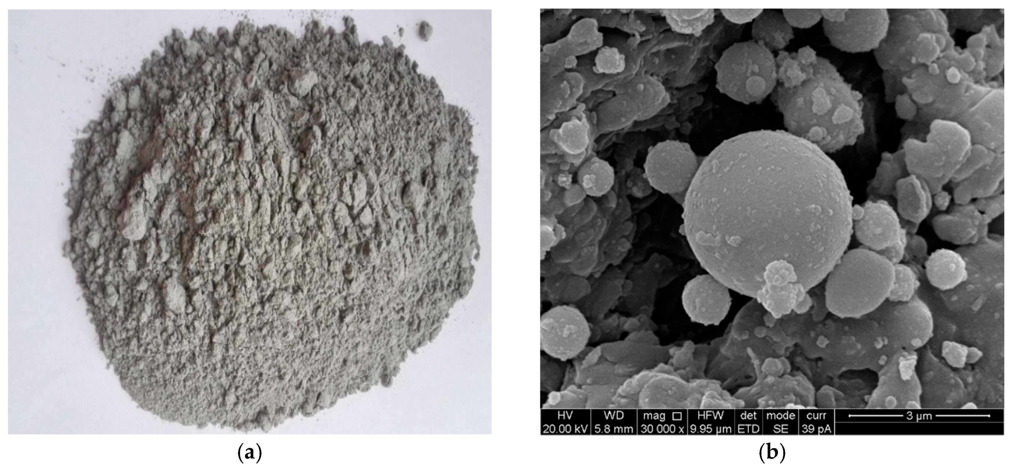
Due to the differences of coal sources, coal types and extraction methods, the performance of fly ash in China is also very different. According to the national standard of China, fly ash is divided into three grades according to its loss on ignition. Fly ash in this paper, obtained from the Huangdao Power Plant in Qingdao City, was light gray in appearance, loss on ignition less than 8%, Class II fly ash. The apparent density is 1950 kg/m
3, and the bulk density is 780 kg/m
3, which contains a large amount of SiO
2 and Al
2O
3. The schematic diagram of fly ash is shown in
Figure 1, indicating that the shape of the fly ash particles is spherical. These chemical compositions and spherical particles are beneficial to exert the pozzolanic and micro-aggregate effects of fly ash [
15]. The routineity and rationality of the fly ash have been verified.
2.2. Test Plan
The ratio of cement: fly ash: gangue of the prepared test piece was 1:4:6, and the mass concentration was 72% [
16,
17,
18]. The material was weighed and poured into a mixer. When the slurry was evenly mixed, it was put into a mold with dimensions of 70 mm × 70 mm × 70 mm. After curing for 1 d, the specimen was demolded and placed in a constant temperature and very humid curing box (relative humidity of 95% and temperature of 20 °C) for 28 d. Standard strength test and chloride ion and dry-wet cycle test were carried out on the test block cured for 28 days.
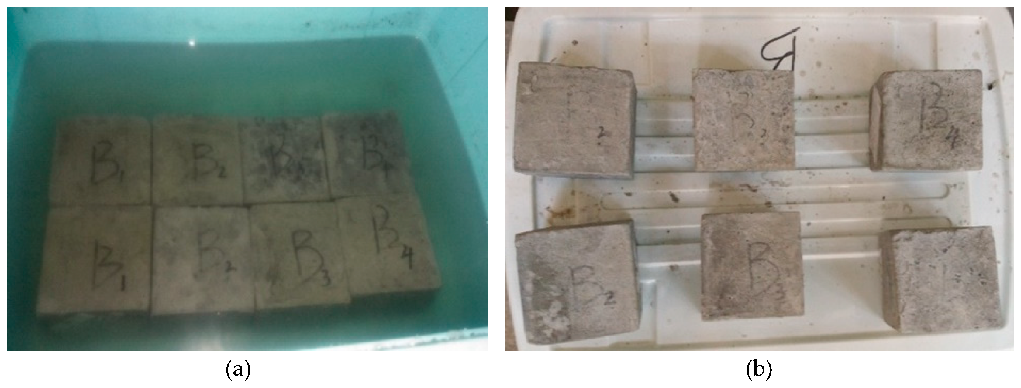
The dry–wet cycle test used a sodium chloride solution with a mass concentration of 10% prepared with analytically pure sodium chloride, as shown in
Figure 2, and the test box containing the sodium chloride solution was placed at room temperature (20 ± 5 °C) and immersed for 7 d. The indoor drying cycle system was 7 d each for dry and wet cycles, which makes it two weeks per dry–wet cycle, for eight such cycles (16 weeks). At the end of each cycle, four test pieces were taken out, and thus, 64 specimens were obtained. Of the 4 specimens taken out each time, 3 were subjected to uniaxial compression test, and the other was subjected to chloride ion penetration test.
2.3. Test Method
The uniaxial compressive strength of all specimens was measured using a Shimadzu AX-G250 testing machine.
The chloride ion penetration depth d was measured by the silver nitrate chromogenic method[
19,
20], and the chloride ion penetration image was processed using digital image technology (DIP). A digital image in a computer consists of a series of pixels arranged in a matrix. In a grayscale image or a binarized image, the grayscale values are 0-1 and 0-255, respectively. The grayscale image of the color rendering surface can finally obtain a two-dimensional matrix, and the essence of image processing is the processing of the two-dimensional matrix.
Then, using a Lemag ZDJ-4B automatic potentiometric titrator and the water extraction method, the free chlorine ion concentration at the color change boundary was determined. Finally, the apparent diffusion coefficient of the chloride ions in the specimen was calculated [
21]. The calculation process is in accordance with the following formulas (1)-(3).
where
w is the mass fraction of chloride ions,
M is the amount of chloride ions (35.45), R is the ratio of water to solid during water extraction,
N is the concentration of the silver nitrate standard titration solution (
mol/L),
V1 is the amount of silver nitrate standard titrant (
mL), and
V2 is the volume of the sample taken (
mL),
c is the chloride ion concentration (
mol/L) at the color change boundary.
Dapp is the apparent diffusion coefficient of chloride ions (
m2∙s-1),
d is the penetration depth of chloride ions measured by the silver nitrate coloration method (
mm),
Ferfc is the inverse function of the error function
Ferf;
c is the color change boundary chloride ion concentration (
mol/L),
ci is the chloride ion concentration on the surface of the test piece (
mol/L), and
t is the chloride ion penetration time (
s).
3. Analysis of Test Results
3.1. Mechanical Parameter Analysis of CPB
The strength value and elastic modulus value of each age are compared with the strength value and elastic modulus value of the specimen cured for 28
d, and the strength change rate
Iσ and elastic modulus change rate
IE are obtained. The calculation formula is shown in formula (4):
In the formula: Iσ, IE are the strength change rate and elastic modulus change rate of CPB under different cycle ages; σn, En are the strength value and elastic modulus value of CPB under different cycle ages; σ0, E0 is the strength value and elastic modulus value of the CPB after curing for 28d.
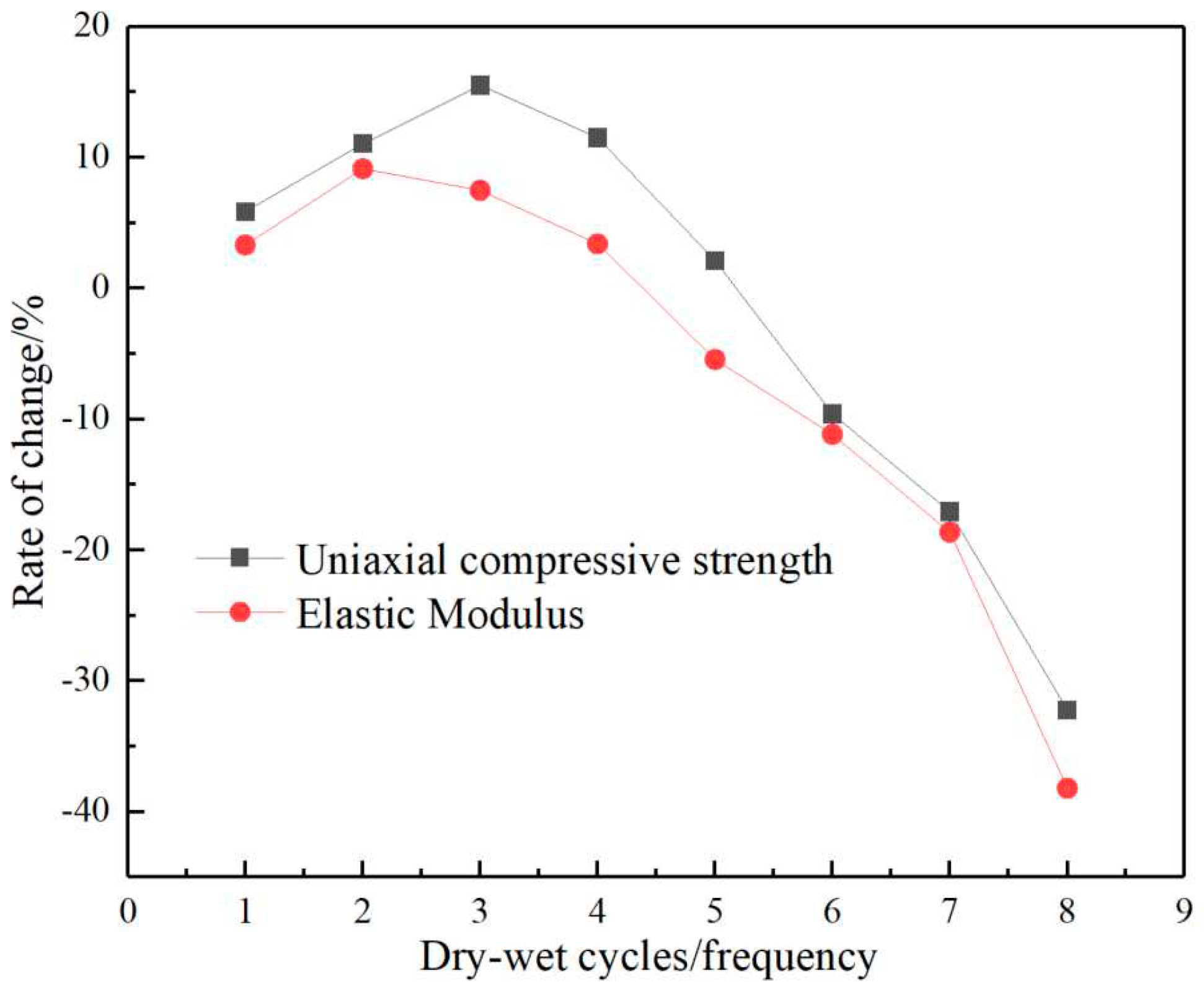
Figure 3 shows the change rates of the UCS and elastic modulus of CPB under different chloride salt and dry-wet cycle conditions. The effect on the strength of CPB is that its UCS does not decrease significantly with the increase of the number of cycles, but shows a trend of first increasing slightly, then decreasing and then decreasing significantly. After the third cycle, its strength value increased by 15.5% compared with that of the uneroded 28
d specimen. After the 4th and 5th cycles, the strength decreased slightly. At this time, the strength of the specimen was still higher than the strength value of the 28
d curing specimen. After the 6th, 7th, and 8th cycles, the strength value decreased by 10.6%, 19.1%, 32.2%.
The effect on the elastic modulus of CPB is that the elastic modulus value first increases and then decreases with the increase of the number of cycles. In the early stage of erosion, that is, after the 1st, 2nd, 3rd, 4th, and 5th cycles, the elastic modulus of the specimens as a whole showed a trend of first slightly increasing and then slowly decreasing, with a maximum increase of 9.5%, which was higher than that of the 28d curing specimens. There is no obvious change in the elastic modulus of the specimens, and the specimens still have good plasticity in the early stage of erosion, and the strengths tested in the same period are all greater than 4MPa, which is beneficial to the joint action of CPB and the surrounding rock to support the roof. In the later stage of erosion, after the 6th, 7th, and 8th cycles, the elastic modulus values decreased by 11.1%, 18.6%, and 38.2%, respectively, compared with the 28d curing specimen, which showed a significant decrease, and the CPB appeared "softened", because the CPB and the surrounding rock jointly bears the roof load. If the elastic modulus of the CPB decreases, most of the roof load acts on the surrounding rock, causing stress concentration and potential safety hazards.
The reason can be explained by stages: In the first three cycles, due to the cement and fly ash contained in CPB, its hydration did not stop completely. The generation of hydration products overcame the damage of chlorine salt to the CPB at the initial stage, so its UCS and elastic modulus increased slightly. However, with the increase of the number of cycles, the hydration is weakened. On the contrary, the erosion caused by chloride is more obvious, and the UCS and elastic modulus of the CPB are greatly reduced.
3.2. Strength Model and Damage Process Analysis of CPB
3.2.1. Damage Constitutive Model of CPB
Material deterioration is a reduction in the effective bearing area due to defects, which can be described in terms of continuity. Assuming that the bearing surface area of the filling material is A in the non-destructive state, under uniaxial loading, the internal cracks continue to develop, and the effective bearing area decreases to
after damage, and the continuity can be defined by a scalar
φ:
A complementary parametric damage variable
D of the degree of continuity
φ is introduced:
When no load is applied to the CPB, it is considered to be in a non-destructive state at this time, and D=0; when it reaches the ultimate damage state, D=1.
The strain equivalence assumption proposed by Lemaitre is widely used to establish damage constitutive equations [
22]. It can be expressed as: for damaged elastic-brittle materials under the action of the true stress σ, the strain in the damaged state is equivalent to the strain of the virtual element under the action of the effective stress
.
Using the strain equivalence assumption, the stress-strain relationship of the damaged material in the one-dimensional case can be expressed as:
Then the damage constitutive relation of CPB under one-dimensional load is:
The damage constitutive model of CPB is established by
:
The damage evolution of CPB is generated by the continuous initiation and expansion of micro-elements. Assuming that there is a relationship
P(ε) between the failure probability of micro-elements and the strain, and the damage distribution is considered to be isotropic, the damage variable
D can be expressed as [
23,
24]:
Assuming that the micro-element failure probability of CPB conforms to the Weibull distribution, the micro-element failure probability density is:
where
m and
n are parameters related to material properties.
Substitute equation (11) into (10) to get:
Substitute equation (12) into equation (9) to get:
Taking the logarithm of equation (13), we get:
Define the stress and strain at the peak load as
and
, respectively, and
at the peak:
in the formula,
,so
, we get:
Substitute equation (16) into equation (14) to get:
Substitute equation (18) into equation (9) to obtain the damage constitutive model of CPB:
According to the stress-strain curve obtained in the uniaxial compressive strength test, the mechanical performance parameters of CPB such as peak stress, peak strain, elastic modulus and the property parameter m can be calculated. The mechanical parameters of CPB under different cycles have obvious Therefore, the damage constitutive models are different.
Table 2 shows the damage constitutive equations at different erosion ages. The fitting coefficients of all models are greater than 0.98, and this damage constitutive model is reasonable and reliable.
3.2.2. Analysis of the Damage Process of CPB
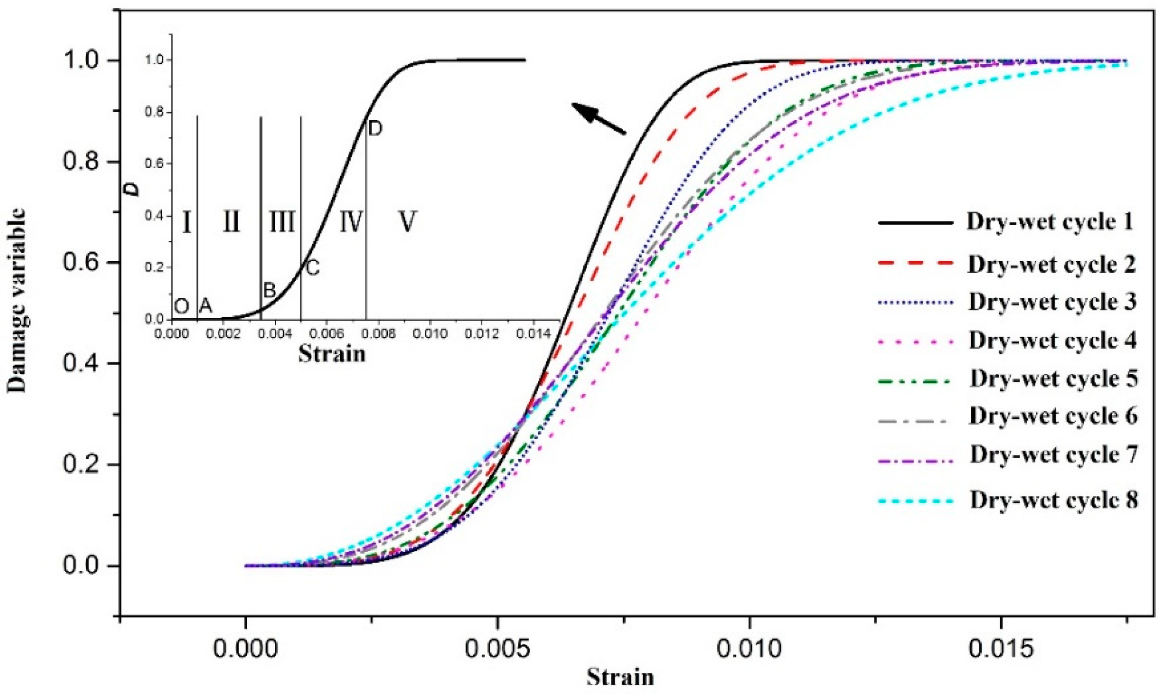
The damage variable D-axial strain curve can be obtained from Equation (12), as shown in
Figure 4. Observe the development characteristics of the damage variables of CPB with different erosion ages, which basically conform to the first slow increase, then a rapid increase, and finally a trend. on a flat trend. Corresponding to the stage division feature points on the stress-strain curve, the damage development process of CPB is divided into the following five stages [
25]:
- (1)
The initial non-damage stage, the OA section, corresponds to the nonlinear compaction stage of the deformation and failure of CPB. The internal micro-cracks are tightly closed, the surface is not damaged, and the damage variable is basically zero.
- (2)
The initial damage stage, the AB segment, corresponds to the linear elastic deformation stage, the internal micro-cracks are initiated and expanded, and new cracks are generated. The damage variable is small but continues to accumulate.
- (3)
Damage development stage, BC section, this stage corresponds to the stage of stable micro-crack expansion, internal micro-cracks develop and penetrate steadily, and macro-cracks gradually form, and the damage variable increases sharply.
- (4)
In the damage destruction stage after failure, the CD segment, this stage corresponds to the failure stage, the CPB has reached the peak strength, and there are still a large number of cracks expanding and converging to continue to damage the internal structure, and the damage variable increases linearly with the increase of strain.
- (5)
Residual damage stage, after point D, this stage corresponds to the residual deformation stage, the CPB is almost completely destroyed under the action of the load, the damage variable rises slowly, and is finally completely destroyed with the increase of strain.
4. Permeability Analysis of CPB
4.1. Analysis of CPB Penetration Test Results
The results of chloride ion penetration experiment are shown in
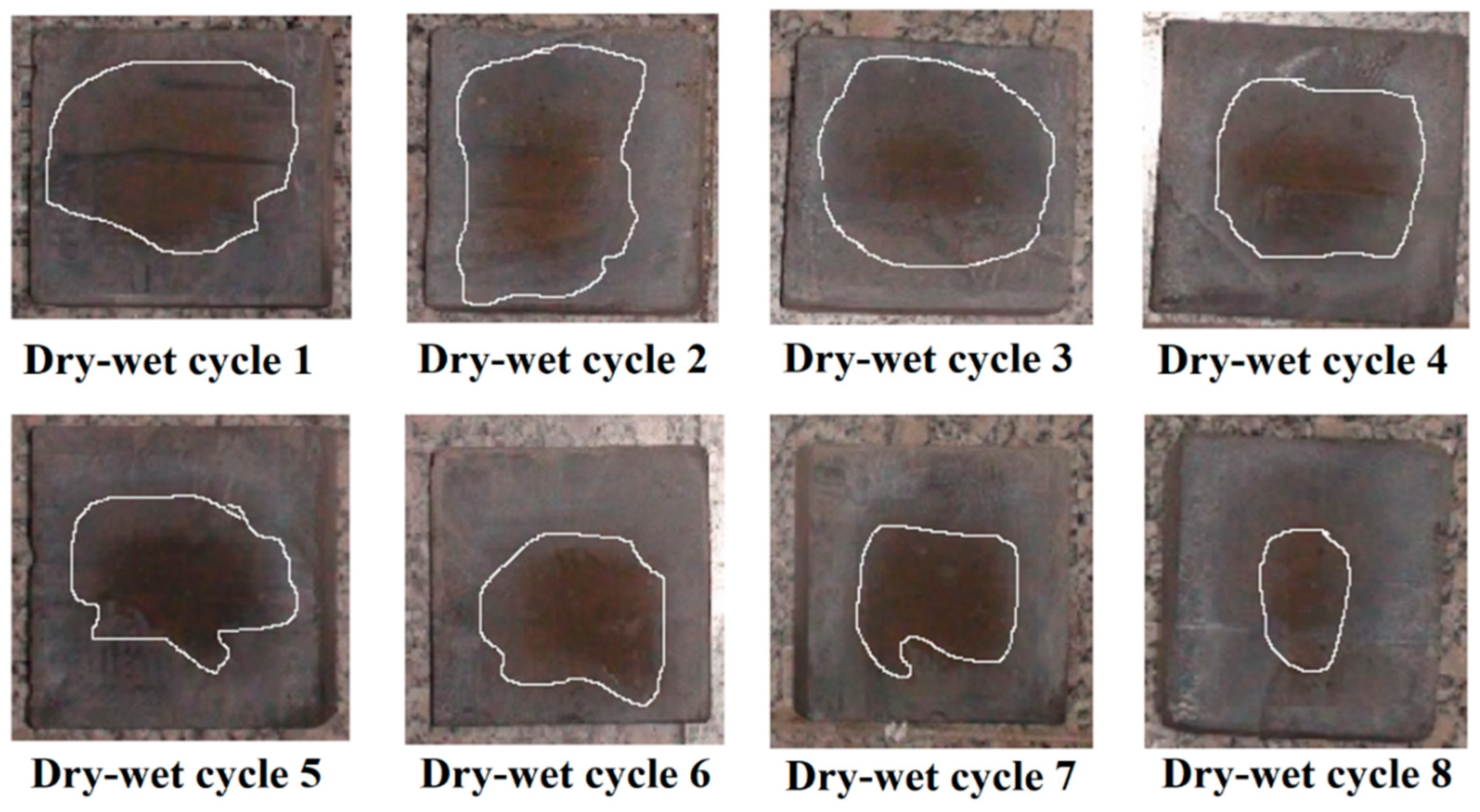
Figure 5. A clear boundary line between the white area and the tan area can be observed on the cross section. The bright white area is the chloride ion penetration area, and the tan area is the non-penetration area.
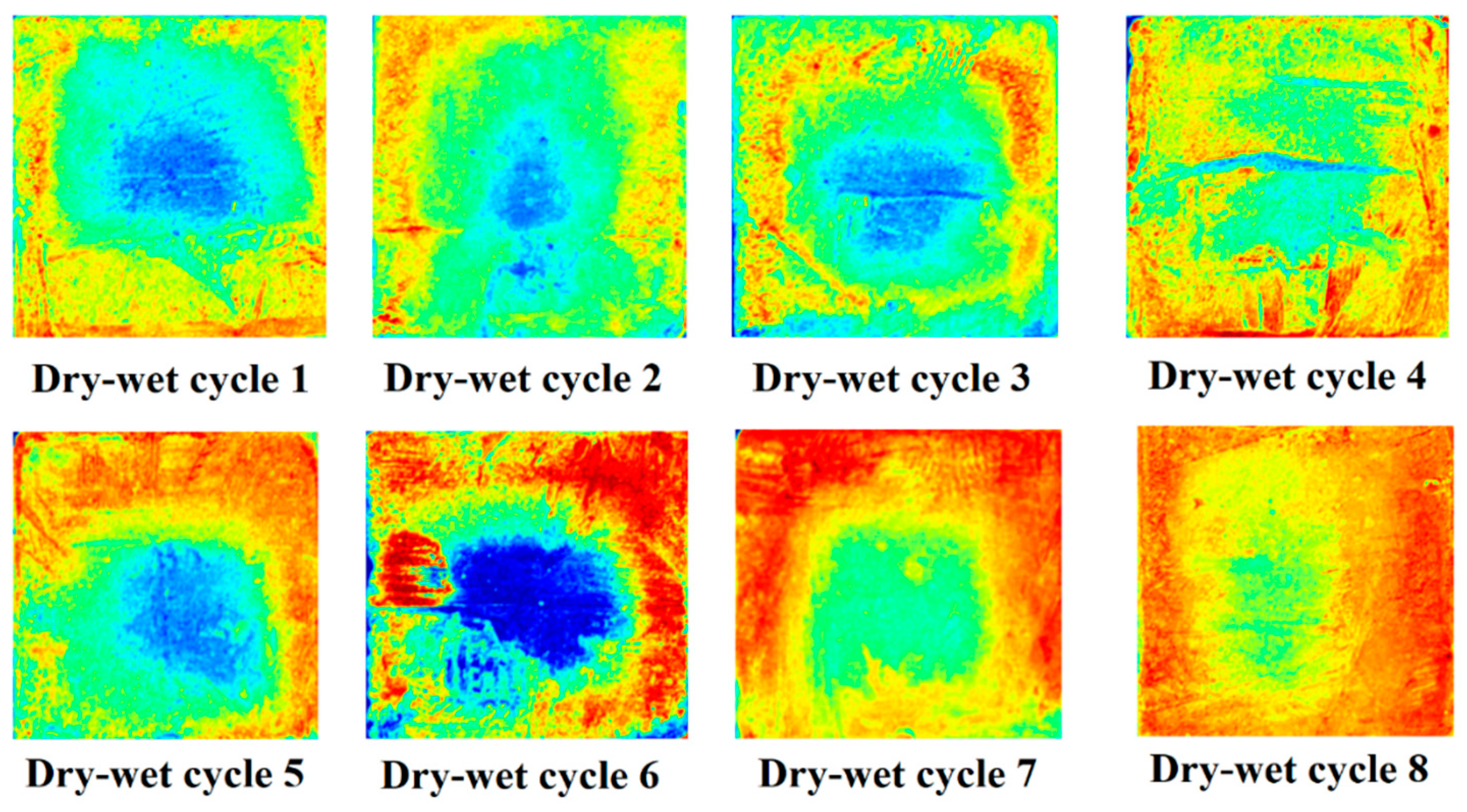
Affected by the color of the section of the specimen, the color boundary is not obvious, which is inconvenient for measurement and calculation. Digital image technology (DIP) is used to process the image.
Figure 6 is an image processed by digital image technology. The yellow area of the picture is the chloride ion penetration boundary area, so the distance from the surface to the boundary can be tested, the red color is the penetration area, and the yellow area to the edge of the specimen is the chloride ion penetration depth. According to
Figure 6, in the first three dry-wetting cycles, there are few red areas, and only a clear yellow boundary appears around the CPB, and the erosion effect is small; That is, the penetration depth of chloride ions increases gradually. During the 8th dry-wetting cycle, the red area penetrated to the center of CPB, and the erosion effect of CPB reached the maximum at this time.
4.2. Analysis of Chloride Ion Penetration Characteristics
The chloride ion concentration at the discoloration boundary is roughly 0.2~0.3 mol/L by calculation. In the early stage of erosion, the concentration value increases rapidly, it is the chloride ion that is continuously accumulated into the material by capillary adsorption and diffusion, but a part of the chloride ion is subject to the chemical combination and physical adsorption of the material itself, so that the measured chloride ion concentration value is low. When the adsorbed chloride ions reach a saturation state, the growth rate decreases, showing a steady upward trend.
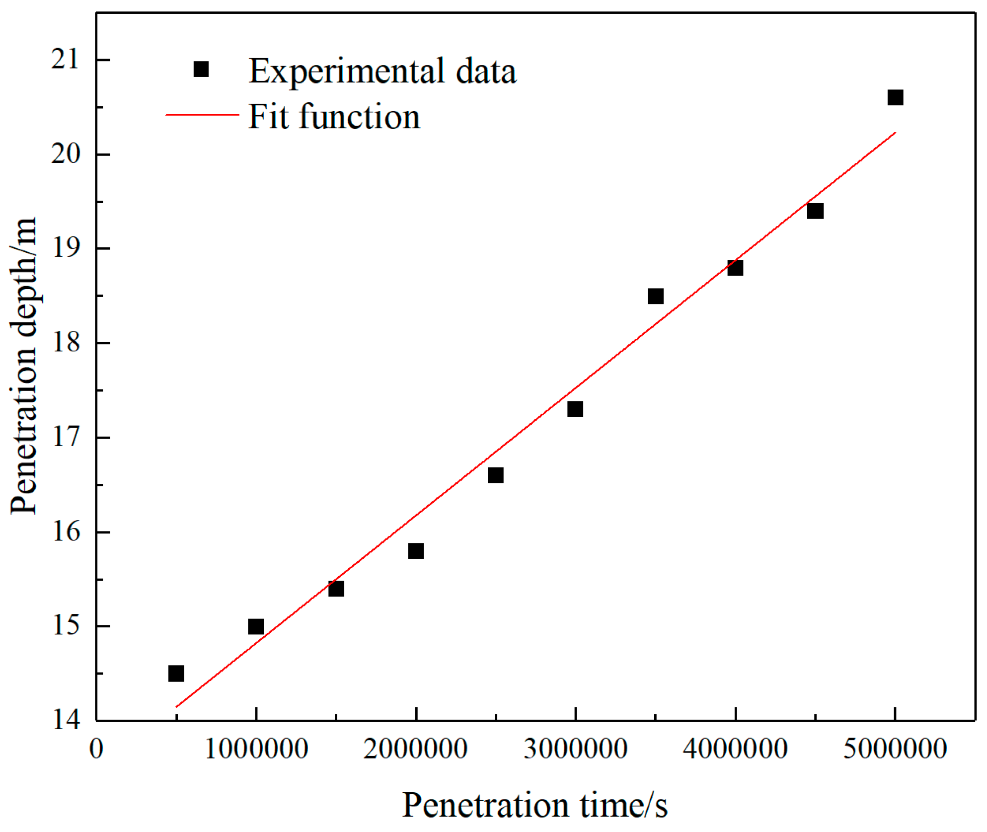
Chloride ions migrate into the material by diffusion, and the penetration depth of chloride ions increases linearly with time. The penetration depth d and penetration time t can be fitted as a linear function, as shown in
Figure 7, the expression is as follows:
In the formula, d-chloride ion penetration depth; t- chloride ion penetration time.
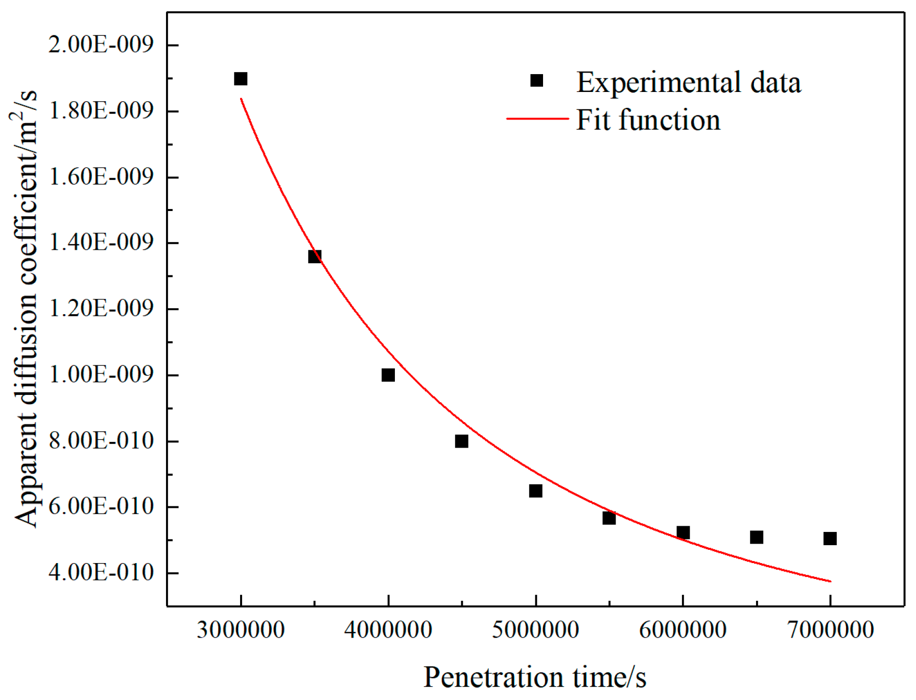
As the erosion age increases, the apparent diffusion coefficient of chloride ions first decreases rapidly and then tends to be stable. This trend can be characterized by a power function, as shown in the formula[
26]:
In the formula, Dapp-the apparent diffusion coefficient of chloride ions of the filling material at any erosion age; D0-the apparent diffusion coefficient of chloride ions at the age t0; t0-the time relative to D0 (usually 28d); m-Environmental attenuation factor.
Use formula (21) to fit the obtained experimental data, and the fitting result is shown in
Figure 8. The function expression of the curve in the
Figure 8 is:
The diffusion coefficient Dapp decreases with increasing erosion time t. In the early stage of erosion, chloride ions have a high level of diffusion rate, which is dominated by capillary adsorption and diffusion, and the diffusion coefficient has an obvious downward trend. It is caused by the phenomenon of chemical bonding and physical adsorption; in the later stage of erosion, the diffusion coefficient decreases gently, and the decline in the last five cycles is only 11.85%. The migration of chloride ions to the deep part of the material is dominated by diffusion, and the secondary Hydration and chemical combination generate large volume of salt, which reduces the porosity of the material, and the diffusion coefficient is relatively small and gradually decreases.
The above has explored the change rule of CPB damage characteristics under chloride dry wet cycle conditions from mechanical experiments and permeability tests respectively. According to the above strength damage and permeability test analysis, the CPB is more seriously damaged under chloride salt and dry wet cycle conditions. In the design experiment in this paper, the strength is reduced by 38.2% at most after only 8 cycles, and the maximum penalty depth of chloride ions is 20.5mm. According to the conclusion of this experiment, we should pay attention to the erosion of chloride dry wet cycle on CPB.
5. Conclusions
- (1)
Under the action of chloride salt erosion and dry-wet cycle, the strength and elastic modulus of the CPB first increased and then decreased rapidly. After the third cycle, its strength and elastic modulus increased by 15.5% and 9.5%, respectively, compared with the strength values of the uneroded 28d specimen. After 8 cycles, the strength decreased by 32.2% and 38.2%, respectively.
- (2)
Based on the assumption of strain equivalence, construct the damage constitutive equation of the backfill under uniaxial conditions. According to the constitutive equation, the damage variable D-axial strain curve of CPB under different erosion ages can be obtained. They also have Similar trend, the damage development process of CPB can be divided into five stages: the initial non-damage stage, the initial damage stage, the damage development stage, damage destruction and the residual damage stage, which is similar to the five stages of the deformation and damage process of CPB. corresponding to the stage.
- (3)
Based on the chloride ion penetration images processed by digital image technology, it is found that the penetration depth of chloride ions gradually increases with the increase of the number of drying and wetting cycles. In the 8th dry-wet cycle, the penetration depth of chloride ions is the largest. At this time, the CPB is subjected to the double erosion of the dry-wet cycle and the chloride salt, which eventually leads to structural damage.
- (4)
The calculation shows that the maximum penetration depth of chloride ions is 20.5mm, the maximum diffusion coefficient is 18.99×10⁻¹⁰m2/s, and the maximum concentration can reach 0.305mol/L. Through function fitting, the development of penetration depth is characterized as a linear function, and the change trend of ion apparent diffusion coefficient is characterized by a power function.
Expectation
Due to the limitation of research time, the number of dry and wet cycles in this paper cannot represent all cycles. Therefore, if other scholars are interested in this, it is recommended to extend the number of dry and wet cycles. Aiming at the research topic of this paper, we have grasped the main existing erosion conditions of a mine: chlorine salt and dry wet cycle. If other scholars are interested in this, they can look for other erosion conditions, such as sulfate, temperature and other factors, or multi factor coupling analysis. In combination with macro and micro tests, we can carry out more detailed mechanism analysis to provide a theoretical basis for more mines.
Author Contributions
LH conducted indoor experimental design and analysis, W HJ conducted theoretical analysis and established a model. All authors read and approved the final manuscript.
Funding
This research was funded by the National Key R&D Program Project Funding (2017YFC0602903); National Key R&D Program Project Funding (2018YFC0603705).
Institutional Review Board Statement
This research does not involve any ethical issues and all participants have agreed.
Informed Consent Statement
All participants in the paper have agreed to publish.
Data Availability Statement
The datasets used and/or analysed during the current study are available from the corresponding author on reasonable request.
Acknowledgments
Thanks to the Shandong University of Science and Technology School of Safety for supporting the test equipment provided in this paper. The authors express their special gratitude to Professor Yin Liu, Professor Sheng-tang Zhang for their constructive comments.
Conflicts of Interest
The authors declare that they have no competing interests.
References
- Cao S, Yilmaz E, Song WD. Fiber type effect on strength, toughness and microstructure of early age cemented tailings backfill. Construction and Building Materials .2020,223:44-54. [CrossRef]
- Kasap T, Yilmaz E, Sari M. Physico-chemical and micro-structural behavior of cemented mine backfill: Effect of pH in dam tailings. Journal of Environmental Management 2022,314:115034. [CrossRef]
- Wu AX, Wang Y, Wang HJ. Status and Prospects of the Paste Backfill Technology. Journal of China Metal Mine 2016,07:1-9.
- Qian MG, Xu JL, Wang JC. Further on the sustainable mining of coal. Journal of China Coal Society .2018,43(1):1-13.
- Zhao K, Yu X, Zhu ST, Yan YJ, Zhou Y, He ZW, Song YF, Huang M. Acoustic emission fractal characteristics and mechanical damage mechanism of cemented paste backfill prepared with tantalum niobium mine tailings. Construction and Building Materials .2020,258:119720. [CrossRef]
- Wu AX, Wang Y, Zhou B. Effect of initial backfill temperature on the deformation behaviour of early age cemented paste backfill that contains sodium silicate. Advances in Materials Science and Engineering.2016, 1075: 1-10. [CrossRef]
- Gouder C, Saravanan U. Modeling diffusion and reaction of sulfates with cement concrete using mixture theory. Acta Mechanica 2018, 229(03):1353-1385. [CrossRef]
- Florea MVA, Brouwers HJH. Modelling of chloride binding related to hydration products in slag-blended cements. Construction and Building Materials. 2014,64(3): 421-430. [CrossRef]
- Mathias M, Nele D. Resistance of concrete and mortar against combined attack of chloride and sodium sulphate. Cement and Concrete Composites.2014, 53: 59-72. [CrossRef]
- Gao M, Liu JH, WU AX, Zhao XH. Corrosion and deterioration mechanism of water-rich filling materials in typical chloride environment. Journal of Central South University (Natural Science Edition) .2016,47(08): 2776-2783.
- Du ZW, Chen SJ, Yin DW, Yao DH, Zhang Z. Experimental study on the stability of paste backfill under chloride erosion environment. Journal of China University of Mining and Technology 2021,50(03): 532-538+547.
- He HK, Wang C. Experimental study on the influence of sulfate-chloride erosion on the stability of backfill. Coal Mine Safety 2021,52(05): 54-58+65.
- Li Ting. Research on risk assessment of groundwater pollution in abandoned mines. China University of Mining and Technology.2014.
- Zhou XL, Liu CW, Feng Bo, Guo BB, Lv YH. Effect of dry-wetting cycle on cement-based composite filling materials. Journal of Engineering Science .2019,41(12): 1609-1617.
- Qiu YB, Wang QP. Study on the pozzolanic activity of fly ash stimulated by Na2SO4. Materials Review.2013, 27(24): 121-124.
- Wang Q, Liu, Zhang HQ, Jiang N. Experimental study on the durability of gangue gypsum filling material. Coal Mining.2014, 01: 3-6.
- Liu Y. Research on the performance of building waste coarse fly ash filling materials. Henan: Yellow River Water Conservancy Press,2015.
- Liu Y, Li H, Wang K, Wu HF. Effects of accelerator–water reducer admixture on performance of cemented paste backfill. Construction and Building Materials.2020, 242:118187. [CrossRef]
- He FQ, Shi CJ, Yuan Q, Xiao P. Calculation of chloride concentration at color change boundary of AgNO3 colorimetric measurement. Construction and Building Materials .2011,41(11):1095-1103. [CrossRef]
- He FQ, Shi CJ, Yuan Q, Zheng K. AgNO3- based colorimetric methods for measurement of chloride penetration in concrete. Construction and Building Materials.2012, 26(01): 1-8. [CrossRef]
- He FQ, Shi CJ, An XP. Measurement of the apparent diffusion coefficient of chloride ions in concrete by silver nitrate colorimetric method. Journal of Silicate.2010, 38(11): 2178-2184.
- Xie HP. Damage mechanics of rock and concrete. Beijing: China University of Mining and Technology Press. 1990.
- Jin L, Xia CC . Research methods and problems of creep damage in theoretical rheological mechanics model. Chinese Journal of Rock Mechanics and Engineering S1: 2012,3006-3014.
- Zhao SG, Su DL, Zhang YL, Wu WR. Research on creep test and statistical damage model of tailings cemented backfill. Metal Mines.2016, 05:26-30.
- Hao YR, Lv JK, Ning S. Acoustic emission and damage evolution of sandstone under conventional compression. Mining Research and Development.2018, 38(07):28-31.
- Zhao TJ . Concrete permeability. Beijing: Science Press.2016.
|
Disclaimer/Publisher’s Note: The statements, opinions and data contained in all publications are solely those of the individual author(s) and contributor(s) and not of MDPI and/or the editor(s). MDPI and/or the editor(s) disclaim responsibility for any injury to people or property resulting from any ideas, methods, instructions or products referred to in the content. |
© 2024 by the authors. Licensee MDPI, Basel, Switzerland. This article is an open access article distributed under the terms and conditions of the Creative Commons Attribution (CC BY) license (http://creativecommons.org/licenses/by/4.0/).
