Preprint
Article

Influence of Applied Loads on Free Vibrations of Functionally Graded Material Plate-Shell Panels

Altmetrics

Downloads

91

Views

47

Comments

0

A peer-reviewed article of this preprint also exists.

Submitted:

09 January 2024

Posted:

10 January 2024

You are already at the latest version

Alerts
Abstract
The influence of applied loads on free vibrations analysis of plates and shells panels made of functionally graded materials is analyzed in the present work. Formulations for the static analysis considering geometrically nonlinear behavior, as well as linear buckling and free vibrations analyses are considered. The calculation of the through-thickness stress distribution is also performed. A finite element model based on a higher order shear deformation theory and using a non-conforming triangular flat plate/shell element with 3 nodes, and 8 degrees of freedom per node is used in the numerical implementation. The results obtained with this numerical model are presented, discussed, and compared with alternative solutions published by other authors in some benchmark applications.
Keywords: 
Subject: Engineering  -   Mechanical Engineering

1. Introduction

Plate/shells panels have applications in a wide range of engineering situations, such as aeronautics and aerospace structural systems, among many others. Structures made of composite materials have been widely used to satisfy high performance demands. In such structures, stress singularities may occur at the interface between two different materials. In functionally graded structures the smooth and continuous variation of the properties, from one surface to the other, eliminates abrupt changes in the stress and displacement distributions. In addition, ceramic phase with the low thermal conductivity can resist high thermal environment while metal phase is strong with mechanical load.
Thousands of research works in plate/shells panels composite structures had been published in the last five decades. More recently also a great number of works had been published in functionally graded material structures with the same type of geometry. For this reason, only some representative works related with the objective of the present investigation are mentioned dealing with functionally graded panels structures [1,2,3,4,5,6,7,8,9,10,11,12,13].
In this paper it is presented the analysis of functionally graded material plate/shells panels subjected to general loadings. The formulation is developed for the calculation of natural frequencies and to study the influence of the applied loads on these natural frequencies. Thus, the formulation has to allow for different analyses: geometrically nonlinear deformation with the through-thickness stress distribution calculations, linear buckling and free vibrations. A finite element model based on a higher order shear deformation theory and using a non-conforming triangular flat plate/shell element with three nodes, and eight degrees of freedom per node is adopted to study the plate/shell structures. This finite element model reveals to be very efficient in the analysis of the proposed structures – easy to model the geometry, low number of total degrees of freedom, good accuracy of results.
An in-house computer program was developed, and the solutions of some illustrative examples are performed and the results are presented and discussed.

2. Formulation of the P-FGM Model

An FGM is made by mixing two distinct isotropic material phases, for example a ceramic and a metal. In this work the material properties of an FGM plate/shell structure are assumed to change continuously throughout the thickness (Figure 1), according to the volume fraction of the constituent materials, given by the Power-Law function – Bao and Wang [14]. In addition, the continuous variation of the materials mixture is approximated by using a certain number of virtual layers k throughout the thickness direction - layer approach. The volume fraction of the ceramic and metal phases for each virtual layer is defined according to the power-law:
V c k = 0.5 + z ̄ h   p ;   V m k = 1.0 V c k
where z ̄ is the thickness coordinate of mid-surface of each layer.
Once the volume fractions of the ceramic and the metal, V c k and V m k , are defined, the Young’s modulus E, the shear modulus G , the Poisson ratio ν , or the mass density ρ of each virtual layer k of the FGM plate/shell can be determined:
E k = V c k E c + V m k E m   ;   G k = V c k G c + V m k G m ν k = V c k   ν c + V m k   ν m   ;   ρ k = V c k   ρ c + V m k   ρ m

2.1. Displacement Fields and Strain-Displacement Relations

The displacement field of the plate/shell domain is based on the Reddy’s third-order shear deformation theory, [12,13]:
u x , y , z = u 0 x , y z   θ y x , y + z 3 c 1 θ y x , y w 0   x v x , y , z = v 0 x , y + z   θ x x , y + z 3 c 1 θ x x , y w 0   y w x , y , z = w 0 x , y
where u 0 ,   v 0 ,   w 0 are displacements of a generic point in the middle plane referred to the local axes - x,y,z directions, θ x ,   θ y are the rotations of the normal to the middle plane, about the x axis (clockwise) and y axis (anticlockwise), w 0 x   ,   w 0 y are the slopes of the tangents of the deformed mid-surface in x,y directions, and c 1 = 4 / 3   h 2 , with h denoting the total thickness of the plate/shell structure.
For the geometrically nonlinear behaviour analysis, the strain tensor is conveniently represented in terms of the linear and nonlinear parts of the strain tensor as:
ε =   ε L + ε N L
The linear strain components associated with the displacement fields defined above can be written in the form:
ε L = ε m + z ε b + z 3   ε b   ε s + z 2   ε s
Therefore, we can write in the detailed form:
ε x x =   u 0     x z     θ y     x + z 3 c 1 θ y x 2 w 0 x 2 + 1 2 u 0 x 2 + v 0 x 2 + w 0 x 2 ε y y =   v 0   y + z   θ x   y + z 3 c 1 θ x y 2 w 0 y 2 + 1 2 u 0 y 2 + v 0 y 2 + w 0 y 2 γ x y =   u 0   y +   v 0   x + z     θ y   y +   θ x   x + z 3 c 1   θ y y θ x x 2 2 w 0 x   y + u 0 x u 0 y + v 0 x v 0 y + w 0 x w 0 y ~ γ x z = θ y + w 0 x + z 2 c 2 θ y w 0 x γ y z = θ x + w 0 y + z 2 c 2 θ x w 0 y

2.2. Constitutive Relations for the FGM Structures

The stress-strain relations are defined based on the stress-strain relations in each layer k, which can be written as follows:
σ k = Q k     ε k
where σ k = σ x σ y σ x y τ x z τ y z T is the stress vector, ε k = ε x ε y γ x y γ x z γ y z T is the strain vector and Q k is the elasticity matrix of the k layer:
Q k = Q 11 Q 12 0 0 0 Q 21 Q 22 0 0 0 0 0 Q 66 0 0 0 0 0 Q 44 0 0 0 0 0 Q 55 k    
Q 1 1 k = Q 22 k = E k 1 ν k 2 ; Q 1 2 k = Q 21 k = ν k   E k 1 ν k 2 ;
Q 4 4 k = Q 5 5 k = Q 6 6 k = E k 2   ( 1 + ν ) = G k
By integrating through the thickness, the linear elastic constitutive equation for each virtual layer k, can be written as:
σ ^ k = D ^ k   ε k = N M M Q Q k = A B D 0 0 B C E 0 0 D E G 0 0 0 0 0 A s C s 0 0 0 C s E s k ε m ε b ε b ε s ε s k
where σ ^ k   are the resultant forces and moments, D ^ k   i s   the constitutive matrix, and the sub-matrices of D ^ are given by:
A , B , C , D , E , G k = Q ̄ k   z k 1 z k ( 1 , z , z 2 , z 3 , z 4 , z 6 )   d z ; A s , C s , E s k = Q ̄ k   z k 1 z k ( 1 , z 2 , z 4 )   d z .

3. Finite Element Approach

A non-conforming triangular plate/shell finite element model having three nodes and eight degrees of freedom per node is used. The degrees of freedom at each node are the displacements, the slopes and the rotations, d i = u 0     v 0     w 0   -   w 0   y     w 0   x   θ x     θ y   θ z i T .  
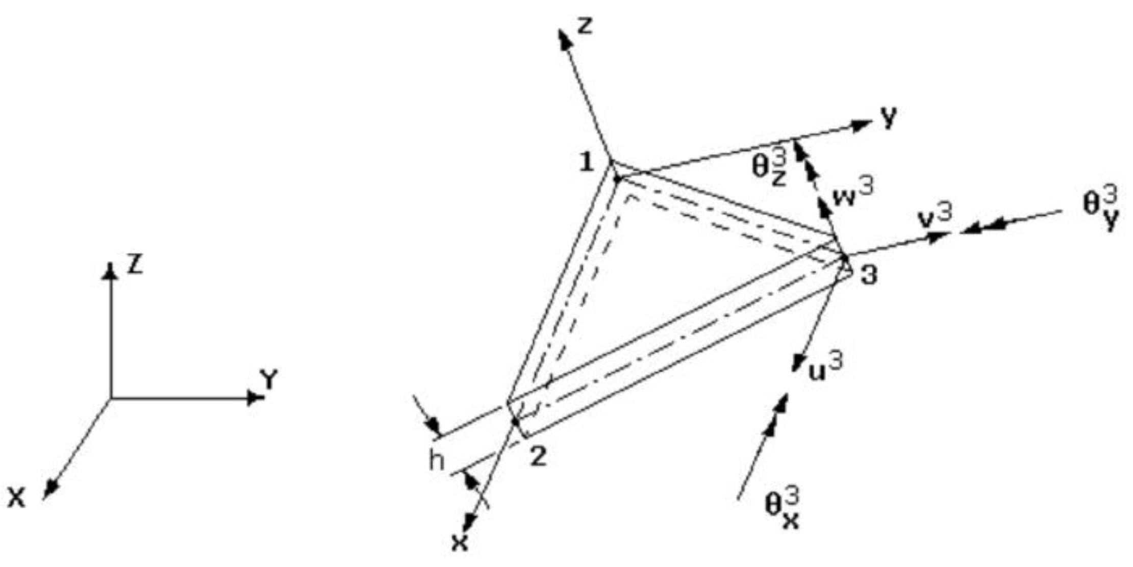
The rotation θ z i is introduced to consider a fictitious stiffness coefficient K θ z to eliminate the problem of a singular stiffness matrix for general shape structures [15]. The finite element formulation is obtained by the superposition of a membrane element with a bending element, and the side 1-2 of the triangle is coincident with the axis x of local system attached to the finite element, with origin at node 1 (Figure 2).
The element displacement vector at any point of mid-surface in local coordinates (x,y) are obtained in terms of the corresponding nodal variables through linear shape functions L i , and the transverse displacement and slopes are expressed in terms of corresponding nodal variables through cubic shape functions N j i , [15], which are also given in terms of area co-ordinates [15].
The displacement field can be represented in matrix form as:
u = Z   ( i = 1 3 N i   d i ) = Z   N   a e   ;   a e = d 1 d 2 d 3 T
where the matrix of shape functions and the appropriate matrix Z containing powers of z k , are:
N i = L i 0 0 0 0 0 0 0 0 L i 0 0 0 0 0 0 0 0 N 1 i N 2 i N 3 i 0 0 0 0 0 N 1 i   y 2 N i   y N 3 i   y 0 0 0 0 0 N 1 i   x N 2 i   x N 3 i   x 0 0 0 0 0 0 0 0 L i 0 0 0 0 0 0 0 0 L i 0
Z = 1 0 0 0 z 3 c 1 0 z + z 3 c 1 0 0 1 0 z 3 c 1 0 z z 3 c 1 0 0 0 0 1 0 0 0 0 0

4. Virtual Work Principle

4.1. Static Analysis

The governing equations of the nonlinear problem are obtained from the virtual work principle in conjugation with an updated Lagrangian formulation [16,17]. A reference configuration is associated with time t and the updated configuration is associated with the current time t = t + Δ t .
k = 1 N t A e h k 1 h k δ ε k L t Q k ε k L t d z d A e t + t A e h k 1 h k δ ε k N L t σ k L t d z d A e t = Π e t t + t k = 1 N t A e h k 1 h k δ ε k L t σ k L t d z d A e t
where Π e t t + t is the element external virtual work.
The membrane, bending and shear strains, as well the higher order bending, and shear strains can be represented by:
  ε m = B m a e   ;   ε b = B b z a e   ;   ε s = B s a e ;   ε b * = B * b z 3 a e   ;   ε s * = B * s z 2 a e
where the   B m , B b , B b , B s , B s , are components of the strain-displacement matrix B , and are given explicitly in Moita et al. [18].
The virtual work principle applied to a finite element, can be written in the following matrix form:
  t A e B T D ^ B a e d A t e + t A e G T τ ^ G   a e d A t e = A e N T p d A e t A e   B T σ ^ t   d A t e
From this equation, it can be obtained the element linear stiffness matrix K L e , the element geometric stiffness matrix K σ e , the element external load vector F e x t e and the element internal force vector F i n t e [18].
The element geometric stiffness matrix   K σ e is given by:
K σ e = t A e G T τ ^ G dA t e
G i = L i x 0 0 0 0 0 0 0 L i y 0 0 0 0 0 0 0 0 L i x 0 0 0 0 0 0 0 L i y 0 0 0 0 0 0 0 0 N i 1 x N i 2 x N i 3 x 0 0 0 0 0 N i 1 y N i 2 y N i 3 y 0 0 0
τ ^ = N x x N x y 0 0 0 0 N x y N y y 0 0 0 0 0 0 N x x N x y 0 0 0 0 N x y N y y 0 0 0 0 0 0 N x x N x y 0 0 0 0 N x y N y y
To solve for general structures, these matrices and vectors, initially computed in the local coordinate system attached to the element, are transformed to global coordinate system in the usual way [15]. Afterwards, by adding the contributions of all the elements in the domain, the system equilibrium equations can be obtained as:
K L + K σ t + Δ t t + Δ t   i 1   Δ q   i = F e x t t + Δ t F int t + Δ t t + Δ t   i 1
Using the Newton-Raphson incremental-iterative method [20], the incremental equilibrium path is obtained, and in the case of snap-through occurrence the automatic arc-length method is used [19] being the Eq. (21) written in the form:
K L + K σ t + Δ t t + Δ t   i 1   Δ q   i = λ i 1 + Δ λ i F e x t 0 F int t + Δ t t + Δ t   i 1
and an additional equation is employed to constrain the length of a load step:
Δ q i T Δ q i = Δ l 2
where F e x t 0 is a fixed (reference) load vector, λ is a load factor, Δ λ is the incremental load factor within the load step, and Δ l is the arc-length.

4.2. Linear Buckling Analysis

For linear mechanical buckling analysis, only one load increment is used, and equation (21) becomes:
K L 0 + K σ 0 q = F e x t 0
The linear elastic buckling standard eigenvalue problem is then given by:
K L + λ c r K σ 0 q = 0   ,         F e x t c r = λ c r   F e x t 0

4.3. Free Vibration Analysis

The Hamilton principle is used to formulate the governing equations for vibration analysis:
t 1 t 2 k = 1 N A e   h k 1 h k   δ ε ̄ k L     Q ̄ k   ε ̄ k L   d z   d t A e A e   h k 1 h k   δ u ˙ T   ρ k   u ˙   d z   d t A e   d t = 0
t 1 t 2 k = 1 N   A e h k 1 h k δ a e T B T Q ̄   B   a e   d z   d A e   A δ a ˙ e T N T   ρ k h k 1 h k Z T Z   d z   N a ˙ e   d A e   d t = 0
where the element mass matrix Me is given by:
M e = A N T   k = 1 N ρ k h k 1 h k Z T Z   d z     N d A e
After assembling all the elements, the natural frequencies and the respective mode shapes are obtained by solving the standard eigenvalue problem:
K L ω 2   M q = 0
The free vibrations of loaded panels are obtained considering the corresponding stiffness matrix by the following equation:
K L + K σ t t ω 2   t t M q = 0

5. Applications

A set of numerical aplications concerning the objective of the present work are presented. With this purpose we present also a few numerical applications, considering different type of analyses whose are necessary to the calculations of the final objective.

5.1. Nonlinear Analysis of a Simply Supported and Clamped FGM Square Plate under Uniform Pressure

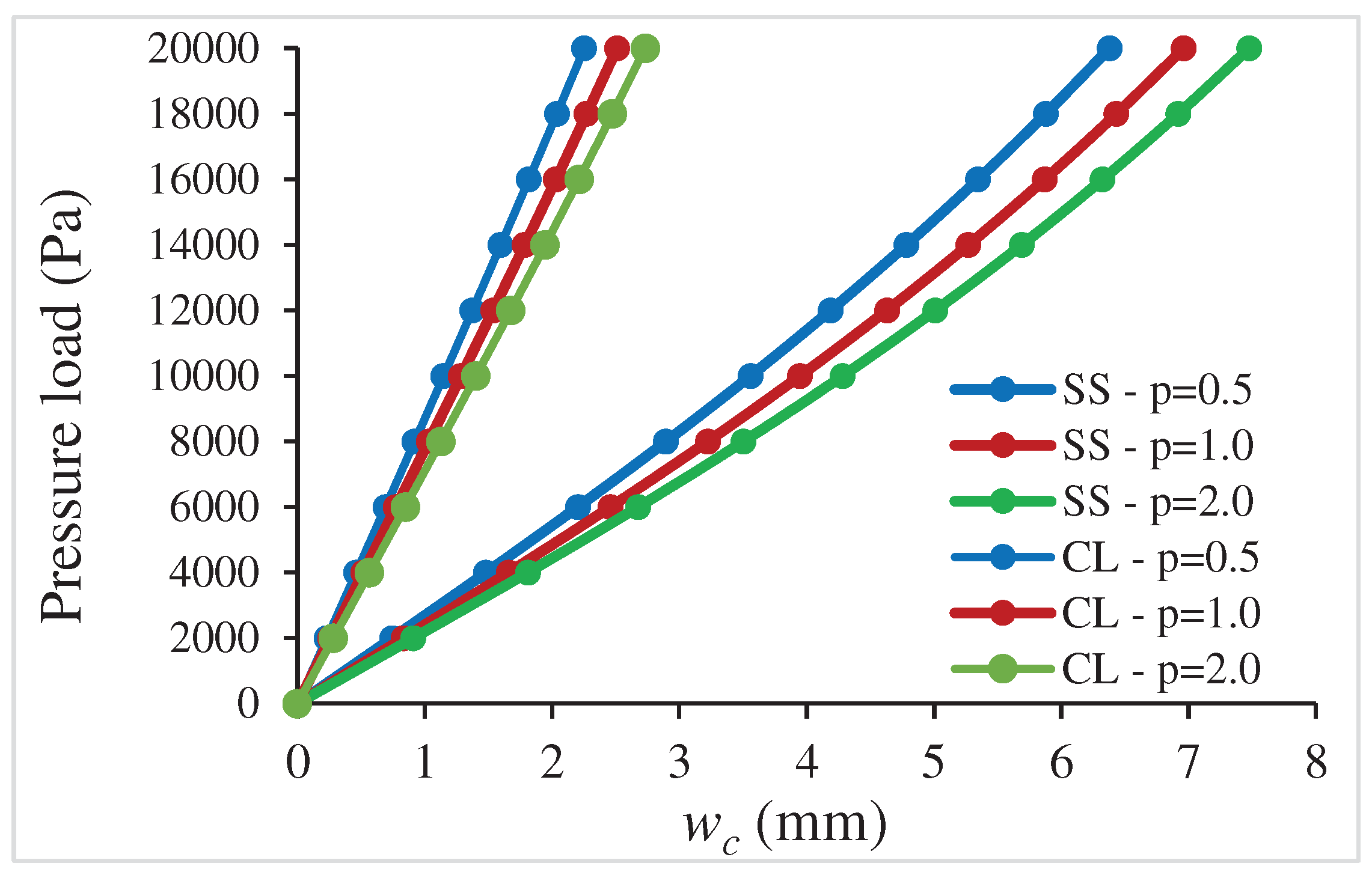
Simply supported (SS) and clamped (CL) FGM square plates subjected to a uniform pressure load are considered in this first numerical application. The geometry is defined by the side dimension a=1.0 m and the thickness h = 0.01 m. Three gradient indexes are considered: p=0.5, p=1 and p=2. The plate, discretized through the thikcness by using 20 virtual layers, is made of constituents zirconia and aluminium (Ec = 151x109 Pa, ν c = 0.3, ρc=5700 kg/m3, Em =70 x 109 Pa, ν m =0.3, ρm=2702 kg/m3). An incremental-iterative loading is applied and the load-displacement paths, obtained for the centre of the plate, are presented in Figure 3. This analysis had been validated in Moita et al. [13], although for different geometry and material properties. It is observed that the displacements increase when the gradient index increases. It happens because Ec>Em, and as p increases the volume fraction of ceramic decreases.
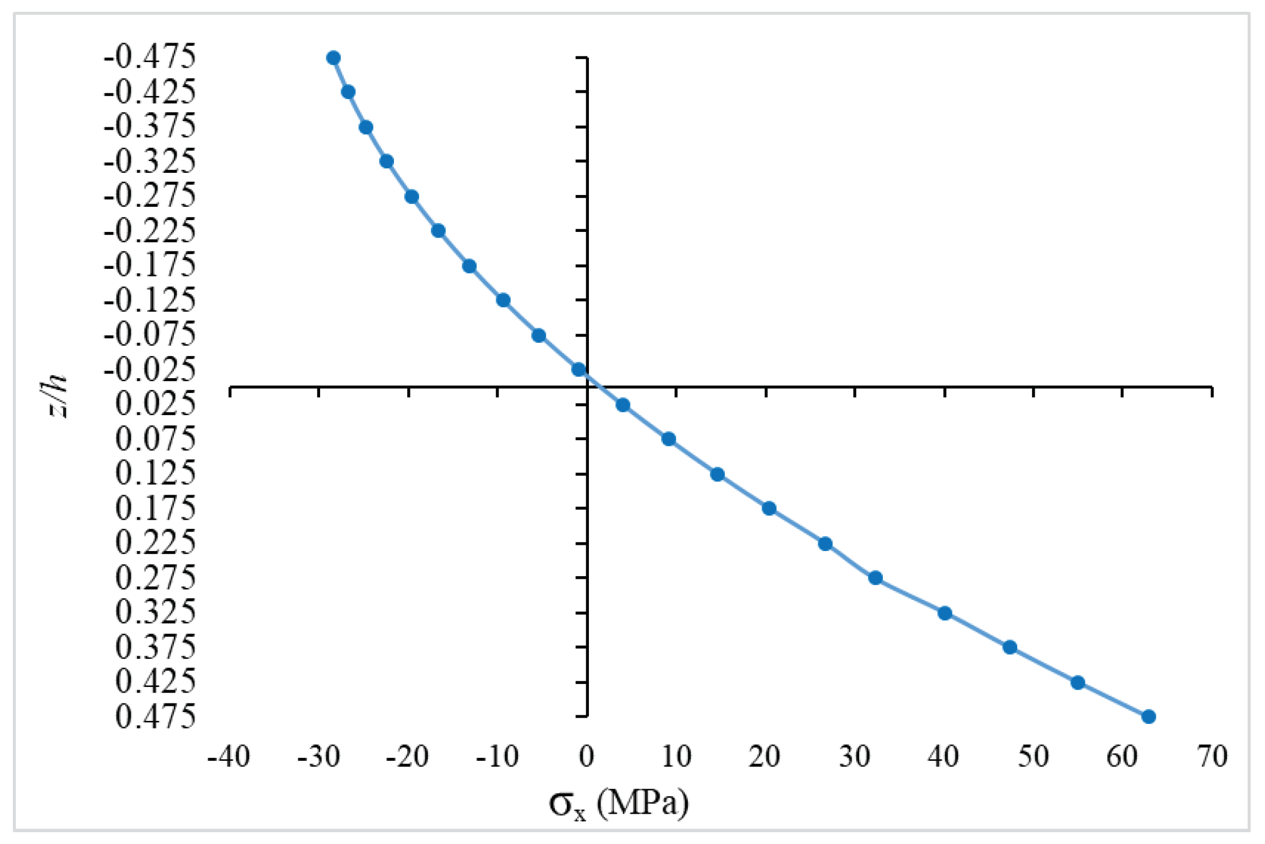
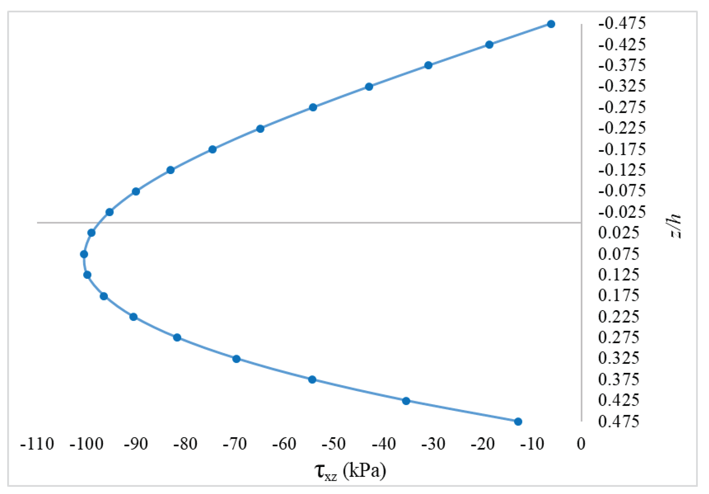
For the last load increment, considering the simply supported plate with gradient index p=1, the through-the-thickness distribution of total normal and transverse shear stresses at Gauss point nearest of centre point of the plate are shown in Figure 4 and Figure 5. It is observed a stress distribution of stresses without abrupt changes in the through-the-thickness as expected.

5.2. Nonlinear Analysis of a Hinged and Clamped FGM Cylindrical Panels under a Centre point Load

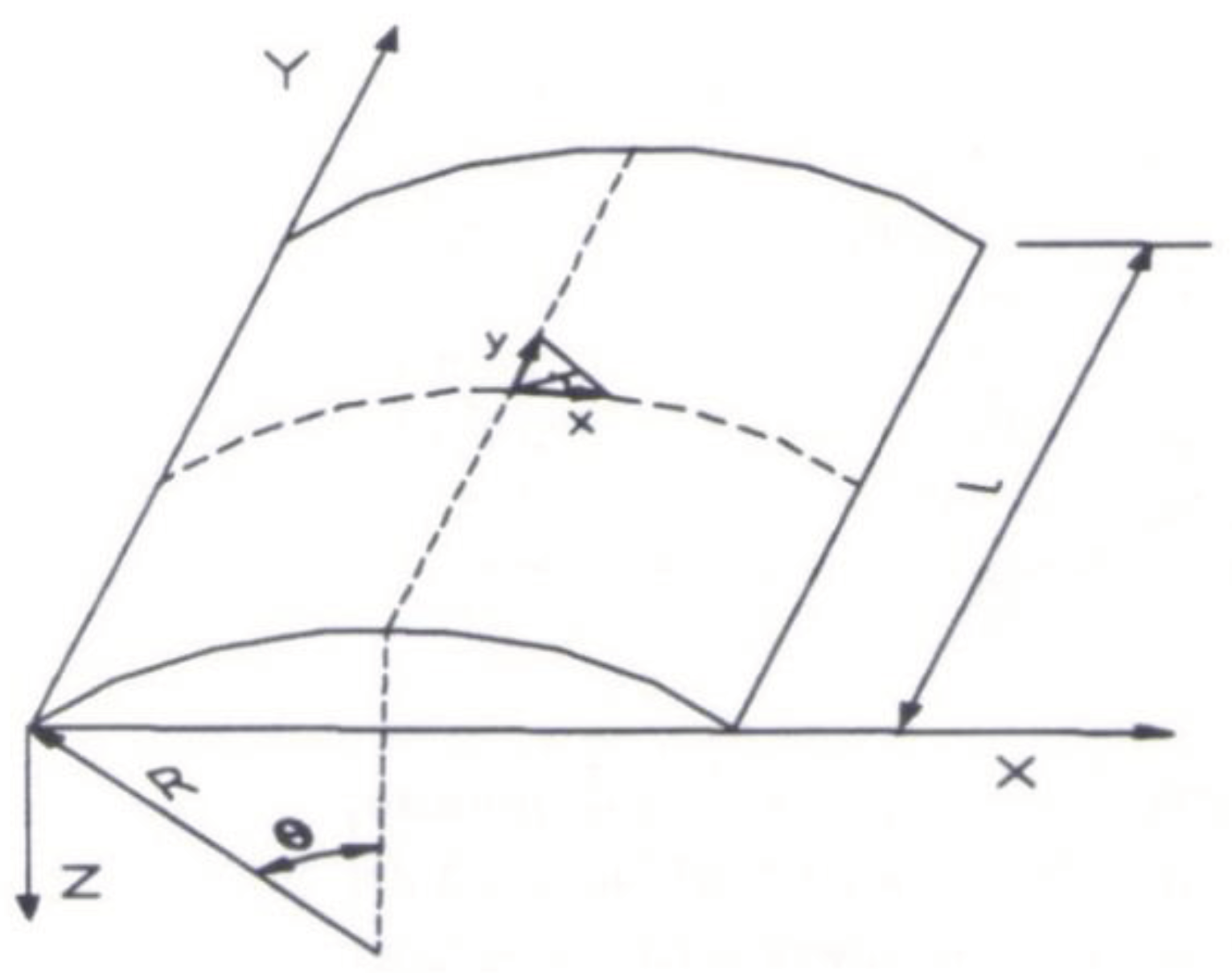
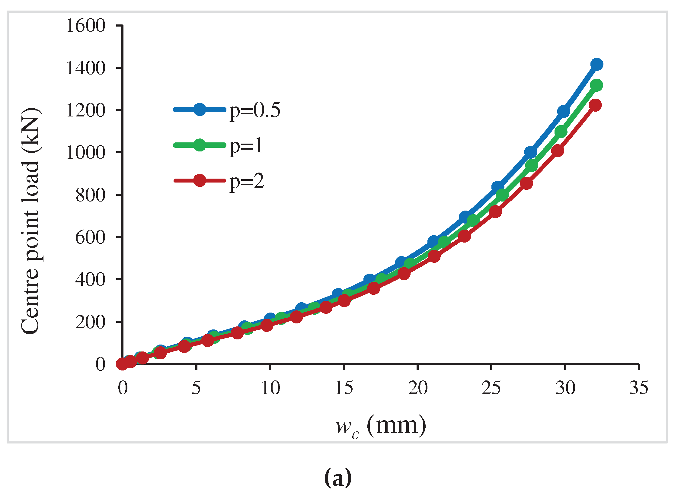
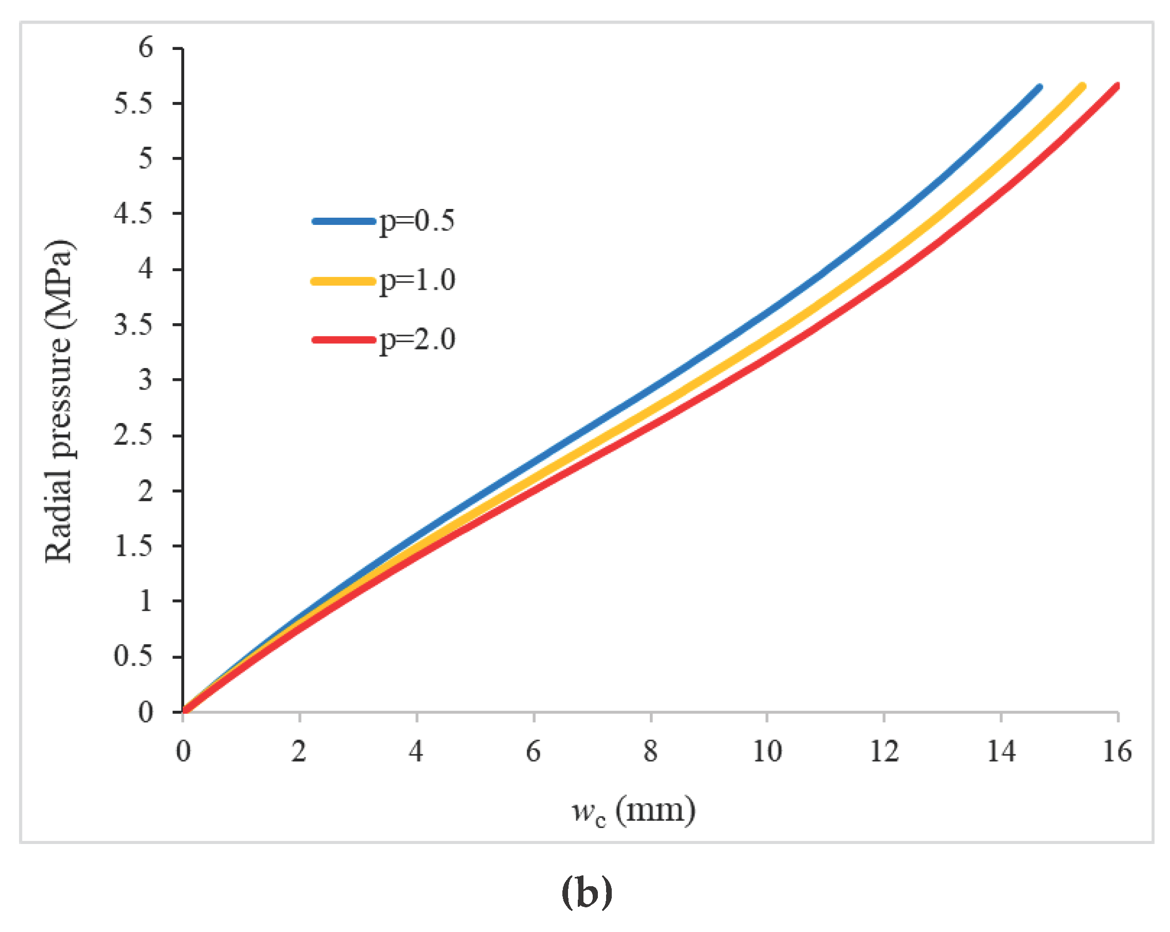
Two FGM cylindrical shell panels (Figure 6), one with the straight sides simply supported (hinged) and the curved sides free, and the other with all sides clamped, are analyzed in this subsection. The geometry is defined by: R= 2.54 m, L = 0.508 m and subtended angle 2 θ =0.2 rad, H=0.0127 m, and it is modelled by 392 triangular finite elements. The constituents are ZrO2 and Ti–6Al–4V with the mechanical properties, respectively: Ec = 168.0 x 10⁹ N/m2, ν c = 0.298, ρc=5700 kg/m3 , Em = 105.7 x10⁹ N/m2, ν m = 0.298, ρm=4429 kg/m3. For this case of geometry and boundary conditions of the cylindrical panel, the snap-through can occur. The results obtained using the present model for the transverse displacement paths, are shown in Figure 7a,b and Figure 8a,b, respectively for the hinged cylindrical panel and for the clamped cylindrical panel. These analysis have been validated in Moita et al. [13], although for different geometry and material properties. It is observed from the paths obtained for the hinged cylindrical panel, that the snap-through do occur, while for the clamped FGM panels, the snap-through do not occur. Also, as expected, the displacements increase when the gradient index increase, considering that Ec>Em. Considering the same cylindrical panel with both boundary conditions, but under radial pressure load, the corresponding load-displacement paths are shown in Figure 7b and Figure 8b.

5.3. Critical Loads of a Clamped FGM Square Plate

The linear buckling loads are obtained first in order to know which values should be considered for the calculations of the free vibrations under uniaxial in-plane applied load.
For the purpose of comparison, a square (a×a) FGM plate with all edges movable and clamped, made of a mixture of zirconia and aluminium (Al/ZrO2), is considered. The material properties for the zirconia and aluminium are respectively, Ec=151.0×10⁹ N/m2, ν c = 0.3 , Em = 70.0×10⁹ N/m2, ν m = 0.3 , side dimension are a=0.2 m and thickness H=0.01m. The FGM plates are under uniaxial compression and the power law index-p ranges from full ceramic to metal. The critical buckling parameters, defined as λ c r = N x x a 2 / D 0 , with D 0 = E m h 3 / 12 ( 1 ν 2 ) , are shown in Table 1. From this table it is observed an excellent agreement between the results obtained with the present model (PM) compared with those obtained by Nguyen-Xuan et al. [20] using the MITC4 model, for the first mode. For benchmarking purposes, the eigenvalues of some higher modes are also presented. Again, as Ec>Em, there is a decreasing in the buckling loads when the p-index increase.
Also for comparison purposes, it is considered a square FGM plate with all edges movable and clamped, but now with H=0.01 m and sides with length a=1.0 m. The material propoetirs are the following: Ec=380.0×10⁹ N/m2, ν c = 0.3 , Em = 70.0×10⁹ N/m2, ν m = 0.3 . The FGM plates are under uniaxial compression and the power law index-p ranges from full ceramic to metal. The critical buckling parameter is now defined as λ c r = N x x a 2 / E c H 3 , and the results obtained with the present model (PM) are compared in Table 2 with the alternative solutions, for the first mode, obtained analytically by Wu et al. [21] using the first-order shear deformation theory.

5.4. Free Vibrations of a Simply Supported FGM Square Plate

The free vibrations of a simply supported FGM square plate are now investigated. The material properties for the zirconia and aluminium are respectively, the following: Ec=151.0×10⁹ N/m2, ν c = 0.3 , ρc=5700 kg/m3, and Em = 70.0×10⁹ N/m2, ν m = 0.3 , ρm=2702 kg/m3. The side dimension is a=0.05 m and the thickness H=0.01m. The non-dimensional frequencies ω ̄ = ω h ρ m / E m   obtained with the present model (PM) are presented in Table 3 and compared with the alternative solutions obtained by Loc et al [9] using a NURBS-based isogeometric approach and a HSDT model. For pure ceramic and pure metal the results are very similar. The discrepancies between the results for FGM plates are attributed to the different homogenization considered - Loc et al. [9] follow the Mori–Tanaka scheme, while the present model uses the rule of mixtures.
The next investigation is to achieve how the free vibrations of a FGM plate with all edges clamped and power-law index p=1.0, are affected by two types of loading, the in-plane loading and transverse loading. The material properties are: Ec=380.0×10⁹ N/m2, ν c = 0.3 , ρm=3000 kg/m3, Em = 70.0×10⁹ N/m2, ν m = 0.3 , ρm=2702 kg/m3. The geometry is defined by a=1.0 m and H=0.01 m. The results obtained are given in Table 4a–c. First, the free vibrations are calculated for the unloaded plate, and afterwards for the three cases of loading:
a) uniaxial in-plane uniform load from px=0 to a final px=2.0; 4.0; 10.0 MPa, and the geometrically nonlinear behavior is considered;
b) transverse uniform load from pz=0 to a final pz=20.0 ; 40.0; 60.0 kPa;
c) uniaxial in-plane uniform load combined with transverse uniform load, ranging from zero to the previously defined magnitudes.
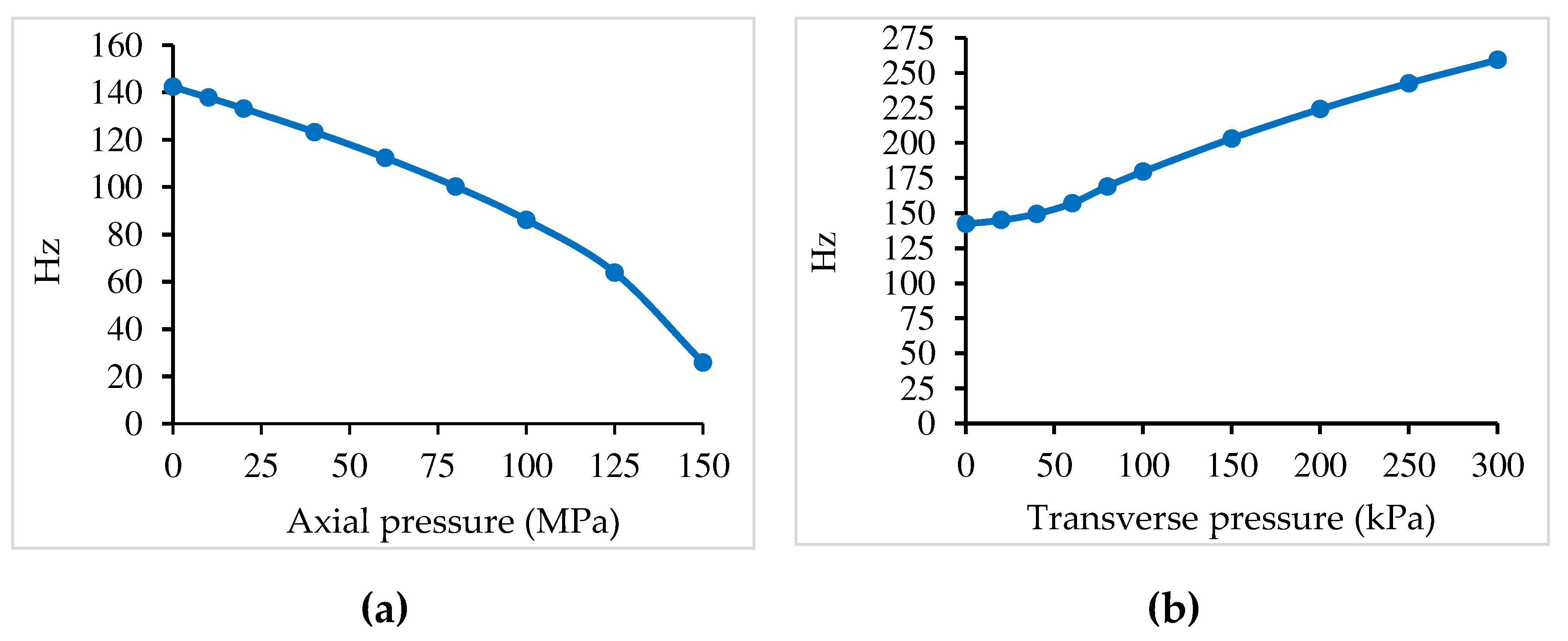
From the Table 4a–c, it is observed that the uniform compressive loading decreases the natural frequencies while the uniform transverse pressure increases the natural frequencies. In addition, it is observed when both types of loads are applied the first frequency increases, but less than when only the transverse pressure is applied, and the other frequencies increase or decrease depending of the values of two types of loadings. Also, it is shown that the magnitude of decreasing/increasing is directly connected with the increase of loading.
Considering the gradient index p=1.0, the influence on the fundamental frequency of the applied loadings is shown graphically in Figure 9a,b for the case of clamped plate, according to Table 4a–c.

5.5. Critical Loads of Hinged and Clamped FGM Cylindrical Panels

To validate the present model, the buckling analysis of a square FGM panel made of a mixture of aluminum and zirconia with the following properties Em = 70.0 x10⁹ N/m2, ν m = 0.3, Ec = 151.0 x 10⁹ N/m2, ν c = 0.3, is considered. The geometry of the panel is length L = 0.1m, angle 2θ = 0.2 rad, radius R = 0.5 m, and thickness h = 0.1 m. The FGM panel is assumed to be with the curved edges fixed and the straight edges simply-supported (FSFS). The panel is under uniaxial compression applied on the curved edges. A 20×20 finite element mesh is used (800 triangular elements). The results for the first three buckling loads parameter N ̄ c r = N c r R / E m h 2 are given in Table 5a for the different power law index considered. From this Table 5, a good agreement with the results obtained by Zhao and Liew [22] is observed for the first buckling load, but with discrepancies varying from 4.5% to 9.5 %, for the second and third buckling loads, respectively. This discrepancies can be related to the different models – HSDT and classical finite element used by present model, and FSDT and mesh-free method used by Zhao et al.
Hinged and clamped FGM cylindrical shell panels are now considered to obtain the critical loads. The geometry and mechanical properties are the same of the subsection 5.2. The results for the non-dimensional buckling loads, λ c r = N y c r R / E m H 2 , obtained using the present model are shown in Table 5b,c, and it is observed that λ c r decreases when the gradient index p increases. It happens because Ec > EFGM > Em.

5.6 Free Vibrations of Hinged and Clamped FGM Cylindrical Panels

First, for comparison purposes, a clampled FGM cylindrical panel with the following geometry: R/10, a/h=100, Ec=380.0×10⁹ N/m2, ν c = 0.3 , ρc=3000 kg/m3, Em = 70.0×10⁹ N/m2, ν m = 0.3 , ρc=2707 kg/m3. The non-dimensional fundamental frequency is given by ω ̄ = ω a 2 ρ m / D m , with D m = E m H 3 / 12 ( 1 ν m 2 ) . The results obtained with the present model are presented and compared in Table 6, with good agreement, with the alternative solutions of Pradyumna and Bandyopadhyay [23] obtained using a higher-order formulation and a C0 finite element, and the solutions published by Ana et al. [24] obtained using a higher-order shear deformation theory and radial basis functions.
The natural vibrations of hinged and clamped FGM cylindrical shells of section 5.2, with the same geometry and material properties, are now analysed. The first three natural frequencies are obtained for the initial geometry (unloaded panel) considering different gradient index p. Next, the cylindrical panel is loaded by three kinds of loads.
1. Hinged FGM panel loaded:
a) by a uniform pressure on the curved side, from py=0 to a final py=20.0 ; 40.0 MPa.
b) by a centre point load, from Pc=0 to a final Pc=20.0 ; 40 kN
c) by a uniform pressure on the curved side, from py=0 to a final py=20.0 ; 40 MPa, combined with a centre point load, from Pc=0 to a final Pc=20.0 ; 40.0 kN.
The geometrically non-linear behaviour is considered, and an incremental-iterative process is used. The results obtained with present model are shown in Table 7a,b. From this Table, it is observed the following:
a) the uniform compressive load increases a little the first two natural frequencies, but decrease a little the third natural frequency.
b) the transverse centre point load decreases more the first three natural frequencies.
c) when both types of loads are applied, the first two frequencies decrease, but less than when only the centre point load is applied.
d) also, it is shown that the frequencies decrease/increase more with the increase of loadings.
2. Clamped FGM panel loaded:
a) by a uniform pressure on the curved side, from py=0 to a final py=25.0 ; 50.0 MPa
b) by a centre point load, from Pc=0 to a final Pc=20.0; 40.0 kN, or by an external radial pressure, form pr=0 to a final pr=2 MPa
c) by a uniform pressure on the curved side, from py=0 to a final py=25.0 ; 50.0 kPa, combined with a centre point load, from Pc=0 to a final Pc=20.0 ; 40.0 kN, or combined with a external radial pressure, from pr=0 to a final pr=1 MPa ; 2 MPa
The corresponding results are shown in Table 8a,b and Table 9a,b. From the Table 8a-b, it is observed the following:
a) the uniform compressive load decreases the first three natural frequencies
b) the transverse centre point load decrease more the first three natural frequencies.
c) when both types of loads are applied, the first three frequencies decrease much more.
d) Also, it is shown that the frequencies decrease more with the increase of loadings.
By comparing the Table 9a,b, it is observed that the external radial pressure decreases more the natural frequencies than the centre point load, as well as their combinations.
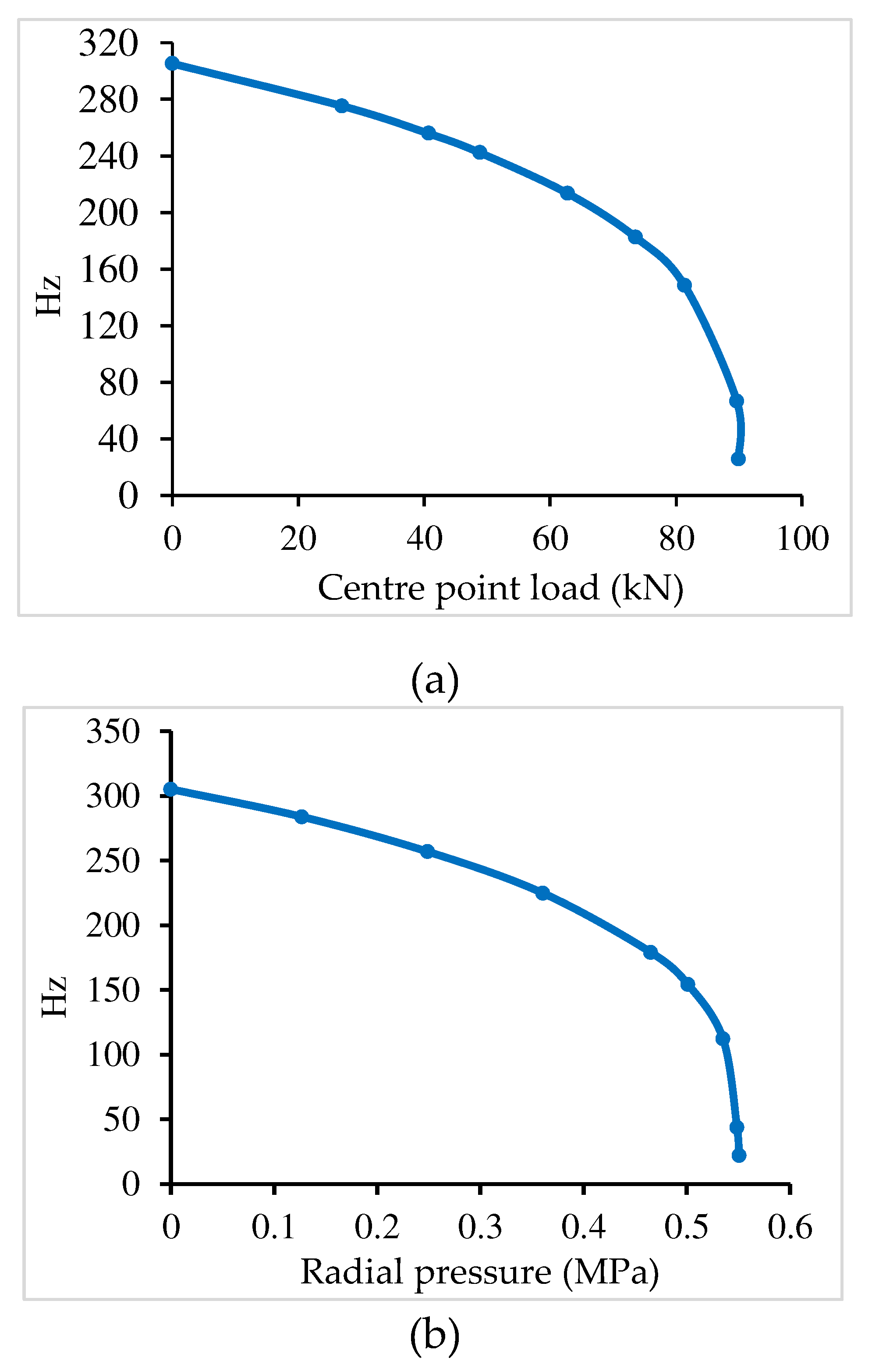
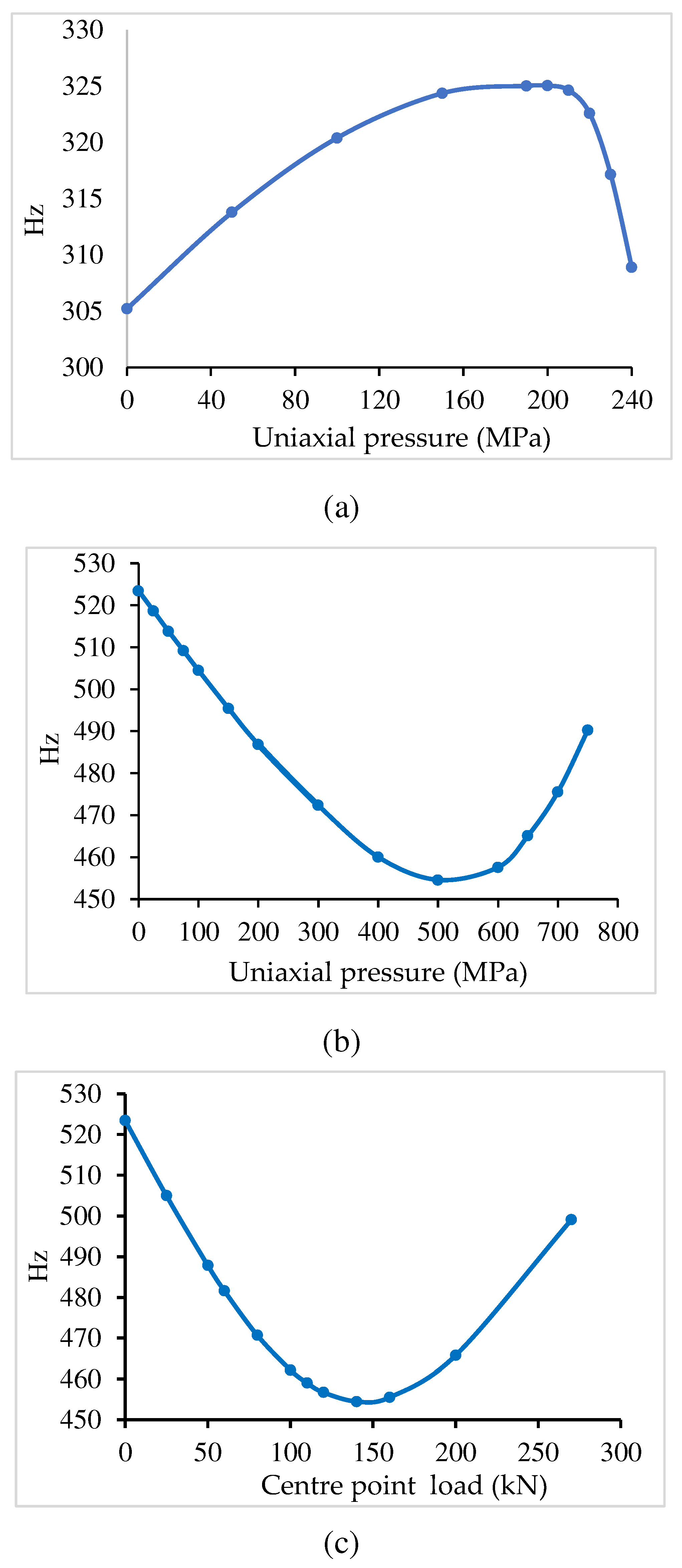
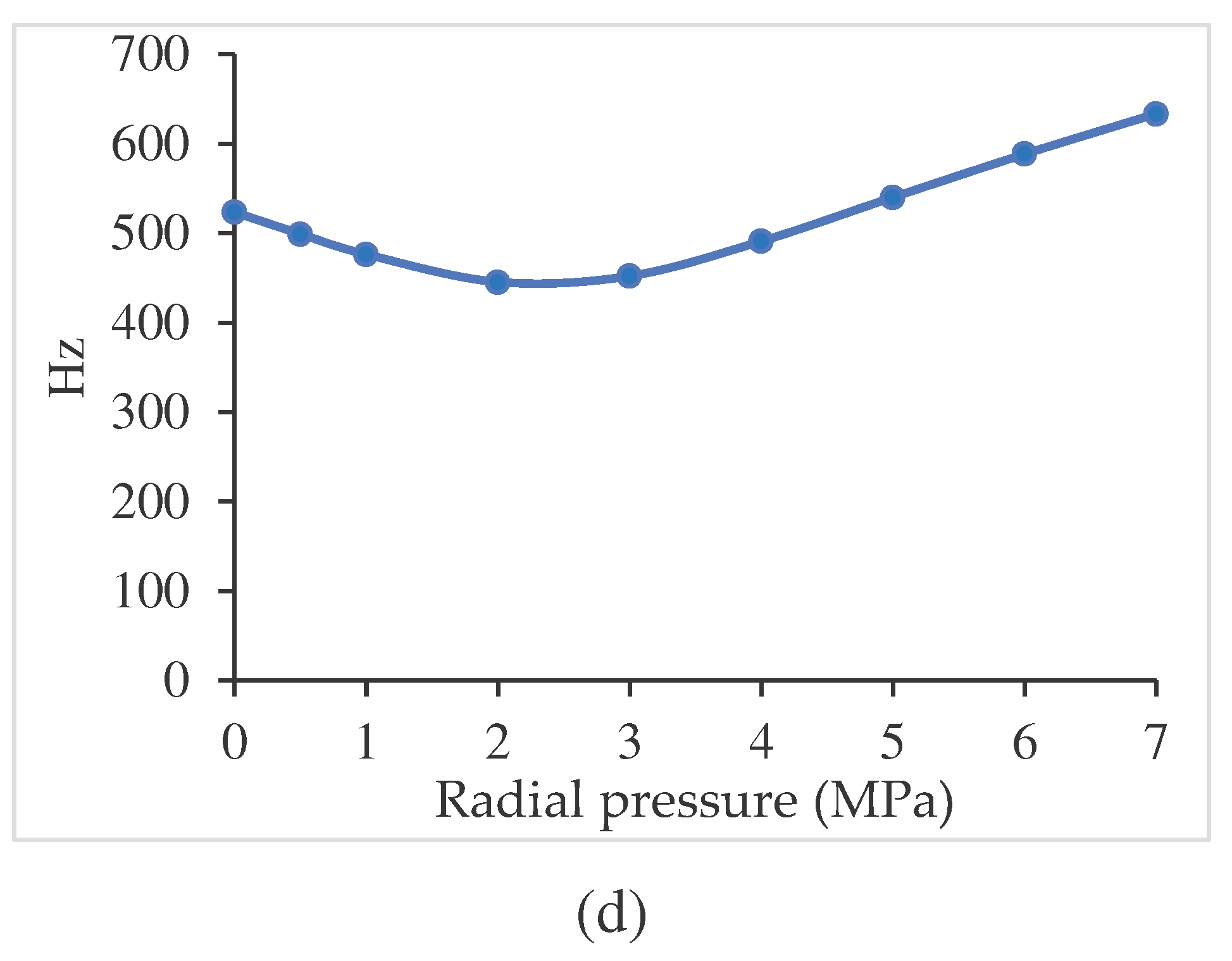
Considering the gradient index p=1.0, the variation of the fundamental frequency versus applied type load and boundary conditions, is shown in Figure 10a–c for the case of hinged cylindrical panels, and Figure 11a–c for the case of clamped cylindrical panels. For the case of hinged panel the fundamental frequency is very low when the centre point load is very near the limit load, but increases under axial pressure. For the uniaxial pressure the linear buckling obtained has been 279.6 MPa. However, using the nonlinear analysis the maximum transverse displacement is obtained at load 200 MPa. For the case of the clamped panel, the fundamental frequency first decreases, but after increases in all types of loading.

6. Conclusions

A finite element model for the free vibration analysis of functionally graded material plates/shell panels under mechanical loading is presented. The loading is done by an incremental-iterative process to consider the geometrically nonlinear deformation of the structures.
The finite element model is based on the Reddy’s third-order shear deformation theory applied to a non-conforming triangular flat plate/shell element with 3 nodes, and 8 degrees of freedom per node.
From the present applications it is observed that the FGM plate/shell structures have a smooth variation of stresses through the thickness, and the free vibrations are influenced by the applied loads:
For clamped FGM plates, the uniaxial compressive load leads to a decreasing of the natural frequencies, while the uniform transverse load leads to an increasing of the frequencies. For clamped FGM cylindrical panels, both type of loads lead to a decreasing of the natural frequencies of the free vibration. In contrary, for hinged FGM cylindrical panels, the uniform uniaxial compressive load leads to an increasing of the first two frequencies, while the centre point load decreases the first three frequencies.
From these observations, it can be concluded that loads applied to plate/shell FGM structures can have significant impact on the natural frequencies, depending of the magnitude of the applied loads.
The authors dedicate this paper to the memory of Professor Rolands Rikards (1942- 2022), who sadly passed away on February 2, 2022. He was World Academic and Distinguished Researcher Expert in the fields of Characterization of Material Properties Multidisciplinary Optimization, Solid Mechanics, Finite Element Techniques, Advanced Composite Materials, and Computational Methods. We extend our sorry to his wife and family and Colleagues at Riga Technical University and to his Friends in Latvia.

Acknowledgements

This work was supported by FCT, Fundação para a Ciência e Tecnologia, through IDMEC, under LAETA, project UIDB/50022/2020.

Conflicts of Interest

The authors declare no conflict of interest.

References

  1. Reddy, JN. Mechanics of Laminated Composite Plates and Shells, 2 nd Edition, CRC Press, 2004.
  2. Barbosa AT, Ferreira AJM. Geometrically nonlinear analysis of functionally graded plates and shells. Mechanics of Advanced Materials and Structures. 2000, 17, 40–48. [CrossRef]
  3. Woo J, Meguid, SA. Nonlinear analysis of functionally graded plates and shallow shells. Int. J. Solids Struct. 2001, 38, 7409–7421. [CrossRef]
  4. Yang J, Shen HS. Nonlinear analysis of functionally graded plates under transverse and in-plane loads. Int. J. Nonlinear Mech. 2003, 38, 467–482. [CrossRef]
  5. Reddy JN, Arciniega RA, Free vibration analysis of functionally graded plates. In: Analysis and Design of Plated Structures: Dynamics. Woodhead Publishing, Cambridge, UK, 2006.
  6. Arciniega RA, Reddy JN. Large deformation analysis of functionally graded shells. International Journal of Solids and Structures. 2007, 44, 2036–2052. [CrossRef]
  7. Kim KD, Lomboy GR, Han SC. Geometrically nonlinear analysis of functionally graded material (FGM) plates and shells using a four-node quasi-conforming shell element. Journal of Composite Materials. 2008, 42, 485–511. [CrossRef]
  8. Zhao Z, Liew KM. Geometrically nonlinear analysis of functionally graded shells. International Journal of Mechanical Sciences. 2009, 51, 131–144. [CrossRef]
  9. Tran, LV, Ferreira, AJM, Nguyen-Xuan, H. Isogeometric analysis of functionally graded plates using higher-order shear deformation theory. Composites Part B: Engineering. 2013, 51, 368–383. [CrossRef]
  10. Valizadeh N, Natarajan S, Gonzalez-Estrada OA, Rabczuk T, Bui TQ, Bordas SPA. NURBS-based finite element analysis of functionally graded plates: Static bending, vibration, buckling and flutter. Composite Structures. 2013, 99, 309–326. [CrossRef]
  11. Natarajan, S, Ferreira, AJM, Bordas, S, Carrera, E, Cinefra, M, Zenkour, AM. Analysis of Functionally Graded Material Plates Using Triangular Elements with Cell-Based Smoothed Discrete Shear Gap Method. Mathematical Problems in Engineering, 2014; Article ID 247932, 1-13. [CrossRef]
  12. Moita JS, Araújo AL, Mota Soares CM, Mota Soares CA, Herskovits J. Material and Geometric Nonlinear Analysis of Functionally Graded Plate-Shell Type Structures. Appl Compos Mater. 2016, 23, 4, 537–554. [CrossRef]
  13. Moita, JS, Araújo, AL, Correia VF, Mota Soares, CM, Herskovits, J. Higher-order finite element models for the static linear and nonlinear behaviour of functionally graded material plate-shell structures Composite Structures. 2019, 212, 465–475. [CrossRef]
  14. Bao, G, Wang L. Multiple cracking in functionally graded ceramic/metal coatings. International Journal of Solids and Structures. 1995, 32, 2853–2871. [CrossRef]
  15. Zienkiewicz, O.C. The Finite Element Method. New York, USA: McGraw-Hill, 1977.
  16. Bathe KJ, Ho, LW. A simple and effective element for analysis of general shell structures. Computers and Structures. 1981, 13, 673–681. [CrossRef]
  17. K.J. Bathe, Finite Element Procedures in Engineering Analysis. Prentice-Hall Inc, Englewood Cliffs, New Jersey, 1982. [CrossRef]
  18. Moita JS, Araújo AL, Martins, PG, Mota Soares, CM, Mota Soares, CA. Analysis of active-passive plate structures using a simple and efficient finite element model. Mechanics of Advanced Materials and Structures. 2011, 18, 159–169. [CrossRef]
  19. Crisfield, MA. A fast incremental/iterative solution procedure that handles snap-through. Computers and Structures. 1980, 62, 13–55. [CrossRef]
  20. Nguyen-Xuan, H, Tran, LV, Thai, CH, Nguyen-Thoi, T. Analysis of functionally graded plates by an efficient finite element method with node-based strain smoothing. Thin-Walled Structures. 2012, 54, 1–18. [CrossRef]
  21. Wu,T-L, Shukla, KK, Huang, JH. Free vibration analysis of functionally graded curved8 panels using a higher-order finite element formulation. Composite Structures. 2007, 81, 1–10. [CrossRef]
  22. Zhao, X, Liew KM. A mesh-free method for analysis of the thermal and mechanical buckling of functionally graded cylindrical shell panels. Comput Mech. 2010, 45, 297–310.
  23. Pradyumna, S, Bandyopadhyay, JN. Free vibration analysis of functionally graded curved panels using a higher-order finite element formulation. Journal of Sound and Vibration. 2008, 318, 176–192. [CrossRef]
  24. Neves, AMA, Ferreira JM, Carrera E , Cinefra, M, Roque, CMC , Jorge, RMN, Soares, CMM. Free vibration analysis of functionally graded shells by a higher-order shear deformation theory and radial basis functions collocation, accounting for through-the-thickness deformations. European Journal of Mechanics A/Solids. 2013, 37, 24–34. [CrossRef]
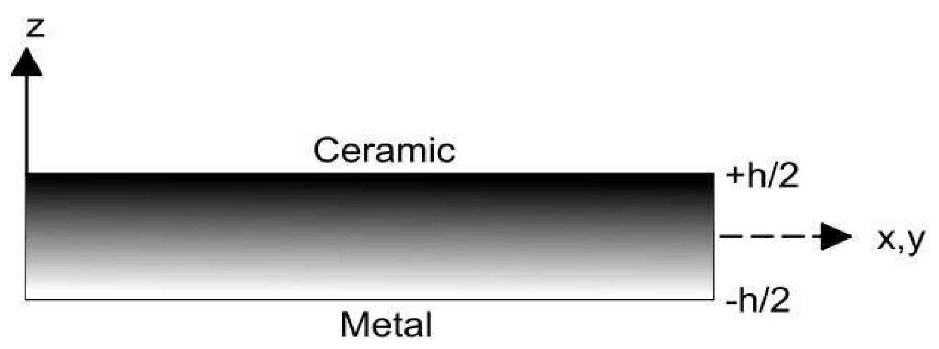
Figure 1. FGM plate representation through the thickness.
Preprints 95963 g001
Figure 2. Finite element.
Preprints 95963 g002
Figure 3. Load-displacement paths for different gradient index.
Preprints 95963 g003
Figure 4. Through-the thickness distribution of total normal stress σx.
Preprints 95963 g004
Figure 5. Through-the thickness distribution of total transverse shear stress τxz.
Preprints 95963 g005
Figure 6. Cylindrical shell panel.
Preprints 95963 g006
Figure 7. (a) Load-displacement paths for the hinged cylindrical panel, under point load. (b) Load-displacement paths for the hinged cylindrical panel, under radial pressure load (p=1).
Preprints 95963 g007
Figure 8. (a) Load-displacement paths for the clamped cylinder panel, under centre point load. Inflection point at 140 kN for p=1. (b) Load-displacement paths for the clamped cylinder panel, under radial pressure load. Inflection point at 2.25 MPa, for p=1.
Preprints 95963 g008aPreprints 95963 g008b
Figure 9. (a) Clamped plate under px (b) Clamped plate under pz.
Preprints 95963 g009
Figure 10. (a) Hinged cylindrical panel. Limit load: 89.92 KN; (b) Hinged cylindrical panel. Limit load: 0.55 MPa.
Preprints 95963 g010
Figure 11. (a) Hinged cylindrical panel. (b) Clamped cylindrical panel. (c) Clamped cylindrical panel. Inflection point at 140 kN. (d) Clamped cylindrical panel. Inflection point at 2.25 MPa.
Preprints 95963 g011aPreprints 95963 g011b
Table 1. Non-dimensional buckling loads for plates with movable and clamped edges and different gradient index, with a/H=20.
Power-law index
mode source ceramic p=0.2 p=0.5 p=1.0 p=2.0 p=5.0 metal
1 PM
1 Ref. [20]
203.833
203.497
181.190
180.331
160.204
159.529
142.854
142.533
130.327
130.342
120.066
120.471
94.492
-
2 PM 230.012 204.622 180.998 161.336 146.936 135.029 106.628
3 PM 372.296 331.653 293.574 261.502 237.458 217.276 172.587
4 PM 473.132 421.549 373.224 332.490 301.889 276.107 219.332
Table 2. Non-dimensional buckling loads for square plates with clamped edges and different gradient index, with a/H=100.
Power-law index
mode source ceramic p=1.0 p=2.0 p=5.0 metal
1 PM
1 Ref. [21]
9.187
9.158
4.606
4.618
3.571
3.579
3.020
3.034
1.690
-
2 PM 10.688 5.342 4.155 3.493 1.969
3 PM 18.099 9.047 7.036 5.908 3.334
Table 3. Non-dimensional frequencies ω ̄ for simply supported plate with different gradient index.
Mode source ceramic p=1.0 p=2.0 metal
1 PM
Ref. [9]
0.2462
0.2461
0.2275
0.2185
0.2254
0.2190
0.2112
0.2113
2 PM
Ref. [9]
0.4539
0.4539
0.4342
0.4118
0.4237
0.4039
0.3899
0.3897
3 PM
Ref. [9]
0.4539
0.4539
0.4342
0.4118
0.4237
0.4039
0.3899
0.3897
4 PM
Ref. [9]
0.5379
0.5385
0.5013
0.4794
0.4930
0.4768
0.4620
0.4623
5 PM
Ref. [9]
0.5379
0.5385
0.5010
0.4794
0.4930
0.4768
0.4620
0.4623
Table 4. (a) Natural frequencies [Hz] for a fully clamped plate under different types of loading (p=1). (b) Natural frequencies [Hz] for a fully clamped plate under different types of loading (p=1). (c) Natural frequencies [Hz] for a fully clamped plate under different types of loading (p=1).
(a)
mode plate unloaded px=2 MPa pz=20 kPa px=2 MPa+pz=20 kPa
1 142.325 141.442 144.252 143.185
2 291.271 290.132 292.259 290.786
3 292.066 291.098 293.134 292.019
4 432.917 431.828 433.395 432.224
(b)
mode plate unloaded px=4 MPa pz=40 kPa px=4 MPa+pz=40 kPa
1 142.325 140.552 149.526 147.391
2 291.271 288.854 295.034 291.357
3 292.066 290.042 295.806 293.672
4 432.917 430.741 435.552 432.328
(c)
mode plate unloaded px=10 MPa pz=60 kPa px=10 MPa+pz=60 kPa
1 142.325 137.843 157.010 154.310
2 291.271 284.797 299.130 292.997
3 292.066 287.177 299.768 296.824
4 432.917 427.461 438.402 433.154
Table 5. (a) The critical buckling load N ̄ c r of a FGM cylindrical panel under uniaxial compression and FSFS boundary conditions. (b) Non-dimensional buckling loads for the hinged cylindrical panel with different gradient index. (c) Non-dimensional buckling loads for the clamped cylindrical panel with different gradient index.
(a)
Source mode p=0 p=0.5 p=1.0 p=2.0 p=5.0
Ref. [22]
PM
1 1.7195
1.7380
1.3700
1.3884
1.2229
1.2316
1.1025
1.1065
0.9949
0.9973
Ref. [22]
PM
2 1.8416
1.9480
1.4575
1.5385
1.3001
1.3669
1.1796
1.2365
1.0750
1.1247
Ref. [22]
PM
3 2.3913
2.2300
1.8863
1.7310
1.6837
1.5331
1.4017
1.3836
1.4018
1.2675
(b)
Power-law index
mode ceramic p=0.5 p=1.0 p=5.0 Metal
1 0.1330 0.1137 0.1060 0.0943 0.0836
2 0.1595 0.1369 0.1277 0.1132 0.1004
3 0.3294 2.9664 0.2680 0.2405 0.2073
(c)
Power-law index
mode ceramic p=0.5 p=1.0 p=5.0 Metal
1 2.0668 1.7809 1.6638 1.4779 1.3004
2 2.1679 1.8604 1.7404 1.5626 1.3640
3 3.4575 2.9664 2.7747 2.4919 2.1754
Table 6. Non-dimensional fundamental frequency ω ̄ for the clamped cylindrical panel with different gradient index.
. Power-law index
Mode source Ceramic p=0.5 p=1.0

1
PM
Ref. [23]
Ref. [24]
102.807
102.923
102.787
86.285
87.545
85.478
77.186
77.077
77.638
Table 7. (a) Natural frequencies [Hz] for hinged FGM cylindrical panel, considering different gradient index and loading type. (b) Natural frequencies [Hz] for hinged FGM cylindrical panel, considering different gradient index and loading type.
(a)
Index p Frequency Hinged
Unloaded
Hinged
py=20.0 MPa
Hinged
Pc=20 kN
Hinged
py=20 MPa
+Pc=20 kN
1 313.274 316.566 295.679 300.890
0.5 2 351.139 355.694 340.132 345.626
3 479.608 479.055 465.256 465.001
1 305.210 310.625 286.167 291.501
1.0 2 343.077 348.121 331.984 337.146
3 473.809 473.269 458.445 458.245
1 297.077 302.268 275.787 281.273
5.0 2 335.446 339.251 321.954 326.915
3 471.027 470.347 454.304 454.022
(b)
Index p Frequency
Hinged
Unloaded
Hinged
py=40.0 MPa
Hinged
Pc=40 kN
Hinged
py=40 MPa
+Pc=40 kN
1 313.274 320.973 276.674 282.668
0.5 2 351.139 353.198 335.139 332.018
3 479.608 478.479 449.294 448.897
1 305.210 313.219 261.988 271.357
1.0 2 343.077 345.654 316.605 322.333
3 473.809 472.696 440.668 440.884
1 297.077 305.536 249.127 258.280
5.0 2 335.446 336.296 305.175 309.792
3 471.027 469.658 434.684 434.823
Table 8. (a) Natural frequencies [Hz] for clamped FGM cylindrical panel, considering different gradient index and loading type. (b) Natural frequencies [Hz] for clamped FGM cylindrical panel, considering different gradient index and loading type.
(a)
Index p Frequency Clamped
Unloaded
Clamped
py=25 MPa
Clamped
Pc=20 kN
Clamped
py=25 MPa
+Pc=20 kN
1 530.354 525.088 517.085 512.525
0.5 2 910.949 906.395 902.049 897.850
3 950.677 940.616 944.500 935.275
1 523.455 518.643 509.337 504.472
1.0 2 899.626 894.811 890.297 885.837
3 938.582 927.958 932.117 922.348
1 515.247 509.832 500.414 494.868
5.0 2 892.631 887.328 882.877 877.858
3 929.081 917.333 922.329 911.439
(b)
Index p Frequency
Clamped
Unloaded
Clamped
py=50 MPa
Clamped
Pc=40 kN
Clamped
py=50 MPa
+Pc=40 kN
1 530.354 521.489 504.152 493.762
0.5 2 910.949 901.861 893.429 884.175
3 950.677 930.478 938.769 919.380
1 523.455 513.874 495.884 484.824
1.0 2 899.626 890.029 881.296 871.642
3 938.582 927.243 926.165 905.783
1 515.247 509.832 486.434 473.780
5.0 2 892.631 881.968 873.564 862.640
3 929.081 905.471 916.220 893.425
Table 9. (a) Natural frequencies [Hz] for clamped FGM cylindrical panel, considering different gradient index and loading type. (b) Natural frequencies [Hz] for clamped FGM cylindrical panel, considering different gradient index and loading type.
(a)
Index p Frequency Clamped
Unloaded
Clamped
py=25 MPa
Clamped
pr=1 MPa
Clamped
py=25 MPa
+ pr=1 MPa
1 530.354 525.746 487.428 483.450
0.5 2 910.949 906.135 878.406 875.414
3 950.677 940.051 928.638 921.602
1 523.455 518.375 478.441 474.085
1.0 2 899.626 894.541 865.624 862.355
3 938.582 927.362 915.678 908.076
1 515.247 509.531 468.468 463.246
5.0 2 892.631 886.980 857.417 853.489
3 929.081 916.673 905.549 896.673
(b)
Index p Frequency
Clamped
Unloaded
Clamped
py=50 MPa
Clamped
pr=2 MPa
Clamped
py=50 MPa
+ pr=2 MPa
1 530.354 521.489 453.350 442.269
0.5 2 910.949 901.862 849.881 842.178
3 950.677 930.474 914.233 895.260
1 523.455 513.874 445.354 432.959
1.0 2 899.626 890.029 837.117 828.118
3 938.582 917.243 902.145 880.988
1 515.247 504.466 439.559 423.800
5.0 2 892.631 881.968 830.819 819.155
3 929.081 905.471 894.629 869.139
Disclaimer/Publisher’s Note: The statements, opinions and data contained in all publications are solely those of the individual author(s) and contributor(s) and not of MDPI and/or the editor(s). MDPI and/or the editor(s) disclaim responsibility for any injury to people or property resulting from any ideas, methods, instructions or products referred to in the content.
Copyright: This open access article is published under a Creative Commons CC BY 4.0 license, which permit the free download, distribution, and reuse, provided that the author and preprint are cited in any reuse.
Prerpints.org logo

Preprints.org is a free preprint server supported by MDPI in Basel, Switzerland.

Subscribe

© 2024 MDPI (Basel, Switzerland) unless otherwise stated