Submitted:
09 January 2024
Posted:
10 January 2024
You are already at the latest version
Abstract
Keywords:
1. Introduction
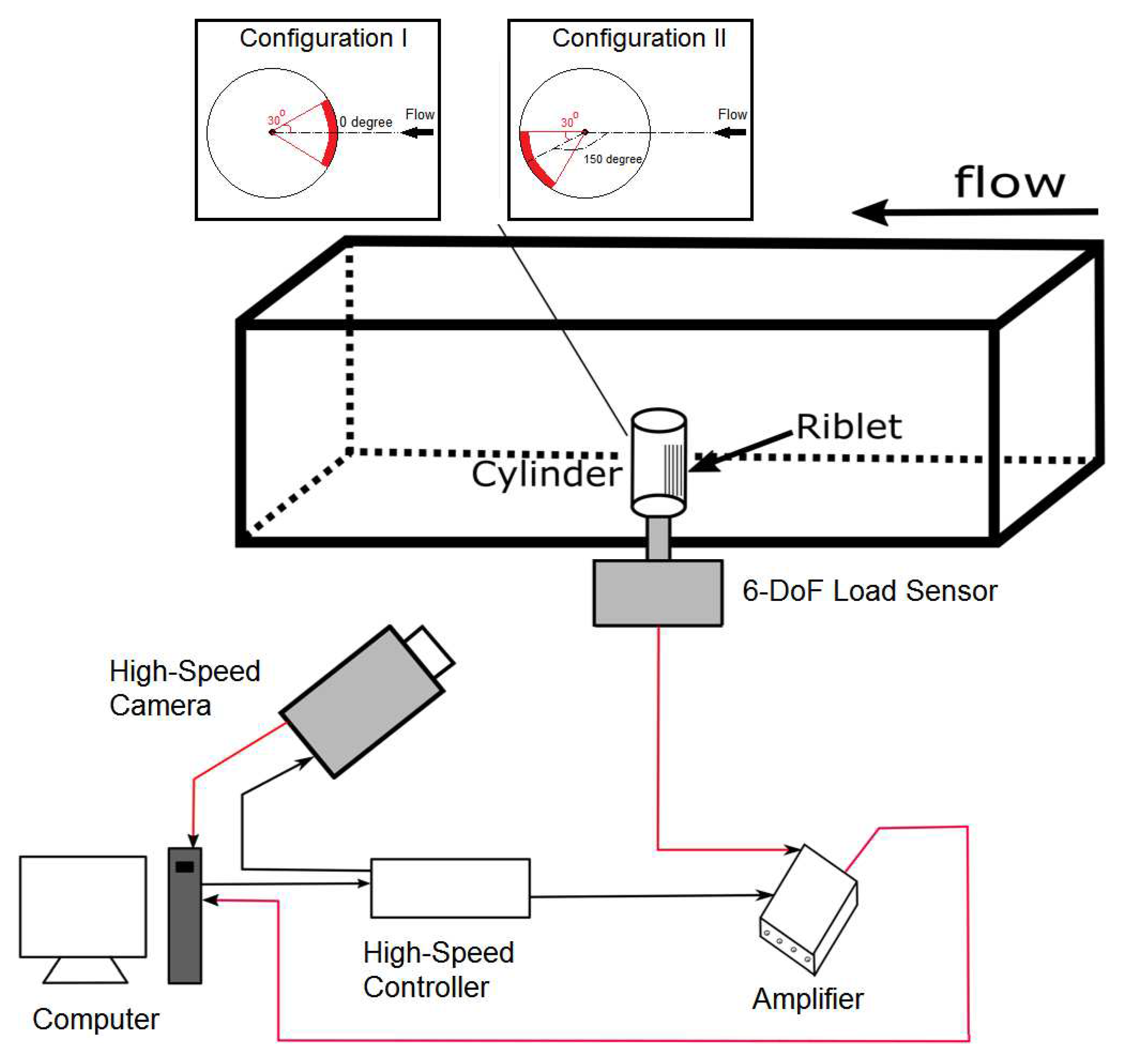
2. Experimental Setup
3. Results and Discussion
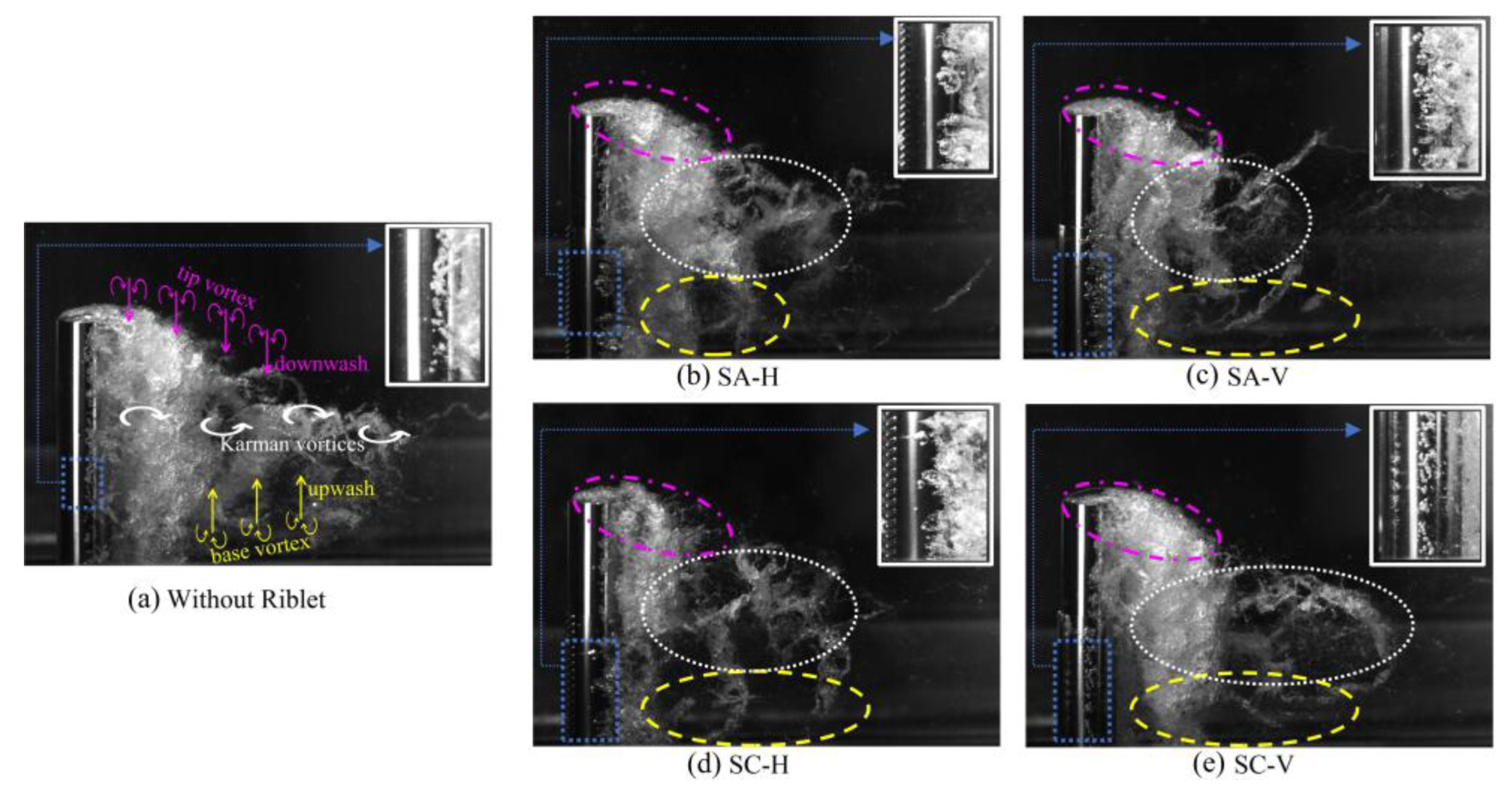
3.1. Cavitation dynamics
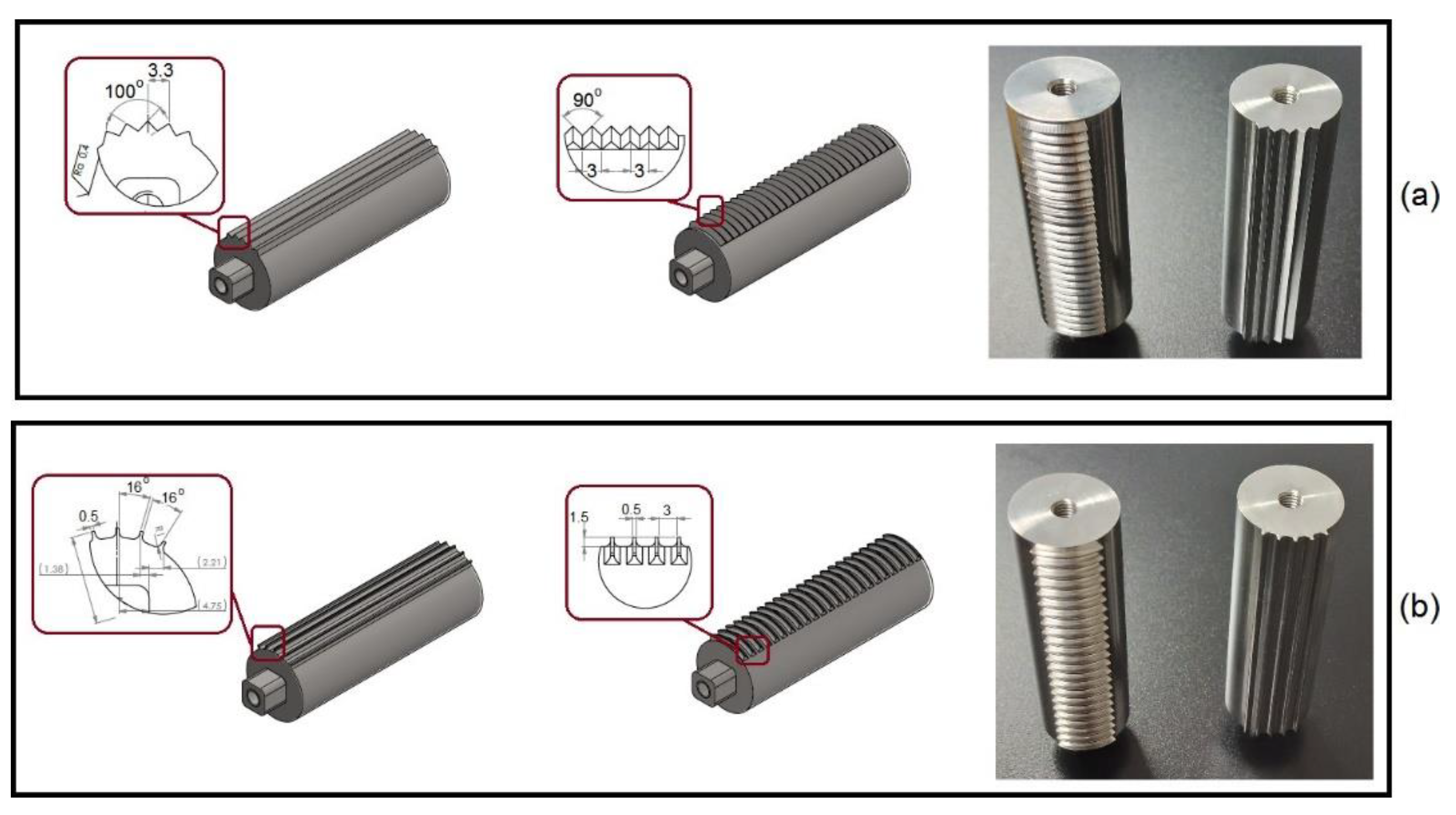
3.2. Morphology of riblets
3.3. Effect of Reynolds number
4. Conclusions
Data Availability Statement
Acknowledgments
References
- Reisman, G., Wang, Y. & Brennen, C. Observations of shock waves in cloud cavitation. J. Fluid Mech. 355 pp. 255-283 (1998). [CrossRef]
- Dular, M., Bachert, B., Stoffel, B. & Sirok, B. Relationship between cavitation structures and cavitation damage. Wear. 257 pp. 1176-1184 (2004). [CrossRef]
- Haosheng, C., Yongjian, L., Darong, C. & Jiadao, W. Experimental and numerical investigations on development of cavitation erosion pits on solid surface. Tribology Lett. 26 pp. 153159 (2007). [CrossRef]
- Patella, R., Choffat, T., Reboud, J. & Archer, A. Mass loss simulation in cavitation erosion: Fatigue criterion approach. Wear. 300 pp. 205-215 (2013). [CrossRef]
- Kadivar, E., el Moctar, O., Sagar, H. Experimental study of the influence of mesoscale surface structuring on single bubble dynamics. Ocean Engineering. 260 pp. 111892 (2022). [CrossRef]
- Lin, Y., Kadivar, E., el Moctar, O., Neugebauer, J. & Schellin, T.E. Experimental investigation on the effect of fluid–structure interaction on unsteady cavitating flows around flexible and stiff hydrofoils. J. Physics of Fluids. 34, pp. 083308 (2022). [CrossRef]
- Franc, J. & Micheal, J. Fundamentals of Cavitation. Kluwer Academic Publishers. (2005).
- Kadivar, E., el Moctar, O., Skoda, R., Lo¨schner, U. Experimental study of the control of cavitation-induced erosion created by collapse of single bubbles using a micro structured riblet. Wear 486-487, pp. 204087 (2021). [CrossRef]
- Arndt, Roger E., and Arthur T. Ippen. Cavitation near surfaces of distributed roughness. Massachusetts Institute of Technology Cambridge 1967.
- Phan, T.-H., Kadivar, E., Nguyen, V.-T., el Moctar, O., Park, W.-G. Thermodynamic effects on single cavitation bubble dynamics under various ambient temperature conditions. Physics of Fluids 34, pp. 023318 (2022). [CrossRef]
- Venning, James A., Bryce W. Pearce, and Paul A. Brandner. Nucleation effects on cloud cavitation about a hydrofoil. Journal of Fluid Mechanics A1, 947. [CrossRef]
- Kadivar, E. Experimental and Numerical Investigations of Cavitation Control Using Cavitating-bubble Generators. PhD Thesis, University Of Duisburg-Essen. (2020).
- Li, Q., Franc, J. & Michel, J. Partial Cavities: Global Behavior and Mean Pressure. Journal Of Fluids Engineering. 115 pp. 243-248 (1993). [CrossRef]
- Callenaere, M., Franc, J., Michel, J. & Rionde, M. The cavitation instability induced by the development of a re-entrant jet. Journal Of Fluid Mechanics. 444 pp. 223-256 (2001). [CrossRef]
- Stutz, B., and J-L. Reboud. Two-phase flow structure of sheet cavitation. Physics of fluids 9.12 pp. 3678-3686 (1997). [CrossRef]
- Leroux, J., Coutier-Delgosha, O. & A. Astolfi. A joint experimental and numerical study of mechanism associated to instability of partial cavitation on two-dimensional hydrofoil. Physics Of Fluids. 17 pp. 1-20 (2005). [CrossRef]
- Leroux, J., Astolfi, J. & Billard, J. An Experimental Study of Unsteady Partial Cavitation. Journal Of Fluids Engineering. 126 pp. 94-101 (2004). [CrossRef]
- Ganesh, H., Ma¨kiharju, S. & Ceccio, S. Bubbly shock propagation as a mechanism for sheet-to-cloud transition of partial cavities. Journal of Fluid Mechanics. 802 pp. 37-78 (2016). [CrossRef]
- Kadivar, E., Ochiai, T., Iga, Y., el Moctar, O. An experimental investigation of transient cavitation control on a hydrofoil using hemispherical vortex generators. Journal of Hydrodynamics. 33 pp. 1139-1147 (2020). [CrossRef]
- Kadivar, E., Timoshevskiy, M., Nichik, M., el Moctar, O., Schellin, T., Pervunin, K. Control of unsteady partial cavitation and cloud cavitation in marine engineering and hydraulic systems. Physics of Fluids. 32 pp. 052108 (2020). [CrossRef]
- Pelz, P., Keil, T. & T. F. Groß, The transition from sheet to cloud cavitation. Journal of Fluid Mechanics. 817 pp. 439-454 (2017). [CrossRef]
- Matsudaira, Y., Gomi, Y. & Oba, R. Characteristics of bubble-collapse pressures in a karman-vortex cavity. JSME International Journal. 35, 179-185 (1992). [CrossRef]
- Saito, Y. & Sato, K. Cavitation bubble collapse and impact in the wake of a circular cylinder. Fifth Int. Symp. Cavitation. pp. 3-8 (2003).
- Kumar, P., Chatterjee, D. & Bakshi, S. Experimental investigation of cavitating structures in the near wake of a cylinder. International Journal of Multiphase Flow. 89 pp. 207-217 (2017). [CrossRef]
- Gnanaskandan, A. & Mahesh, K. Numerical investigation of near-wake characteristics of cavitating flow over a circular cylinder. Journal of Fluid Mechanics. 790 pp. 453-491 (2016). [CrossRef]
- Dobroselsky, K. Cavitation streamlining of a round cylinder in the critical range. J. Phys. Conf. Ser. pp. 1-7 (2020). [CrossRef]
- Brandao, F., Bhatt, M. & Mahesh, K. Numerical study of cavitation regimes in flow over a circular cylinder. Journal of Fluid Mechanics. 885 pp. A19 (2019). [CrossRef]
- Gu, F., Huang, Y. & Zhang, D. Cavitation of multiscale vortices in circular cylinder wake at Re = 9500. Journal of Mar. Sci. Eng. 9, 1-7 (2021). [CrossRef]
- Sadri, M., Kadivar, E. Numerical investigation of the cavitating flow and the cavitation-induced noise around one and two circular cylinders. Ocean Engineering. 277 pp. 114178 (2023). [CrossRef]
- Custodio, D., Henoch, C. & Johari, H. Cavitation on hydrofoils with leading edge protuberances. Ocean Eng. 162 pp. 196-208 (2018). [CrossRef]
- Hao, J., Zhang, M. & Huang, X. The influence of surface roughness on cloud cavitation flow around hydrofoils. Acta Mech. Sin. 34 pp. 10-21 (2018). [CrossRef]
- Zhao, W. & Wang, G. Research on passive control of cloud cavitation based on a bionic fin-fin structure. Eng. Comput. 37 pp. 863-880 (2020). [CrossRef]
- Zhang, L., Chen, M. & Shao, X. Inhibition of cloud cavitation on a flat hydrofoil through the placement of an obstacle. Ocean Eng. 155 pp. 1-9 (2018). [CrossRef]
- Che, B., Chu, N., Schmidt, S., L. Cao, Likhachev, D. & Wu, D. Control effect of micro vortex generators on leading edge of attached cavitation. Physics of Fluids. 31 pp. 044102-1-044102-12 (2019). [CrossRef]
- Che, B., Chu, N., Cao, L., Schmidt, S., Likhachev, D. & Wu, D. Control effect of micro vortex generators on attached cavitation instability. Physics of Fluids. 31 pp. 064102-1-064102-11 (2019). [CrossRef]
- Kadivar, E., Timoshevskiy, M., Pervunin, K., el Moctar, O. Cavitation control using cylindrical cavitating-bubble generators (CCGS): experiments on a benchmark cav2003 hydrofoil. International Journal of Multiphase Flow. 125 pp. 103186 (2020). [CrossRef]
- Kadivar, E., el Moctar, O. Investigation of cloud cavitation passive control method for hydrofoils using Cavitating-bubble Generators (CGs). In: Proceedings of the 10th International Symposium on Cavitation, Baltimore, USA. [CrossRef]
- Simanto, R., Hong, J., Kim, K., Ahn, B. & Shin, S. Experimental investigation on cavitation and induced noise of two-dimensional hydrofoils with leading-edge protuberances. Physics of Fluids. 34 pp. 124115 (2022). [CrossRef]
- Yu, F., Zhang, Y., Liu, H., Zhou, Q. Experimental and numerical investigation of cavitation control with porous material on the hemisphere cylinder. J. Ocean Engineering. 266 pp. 112984 (2022). [CrossRef]
- van Rijsbergen, M. A review of sheet cavitation inception mechanisms. IS-ROMAC2016–International Symposium on Transport Phenomena and Dynamics of Rotating Machinery, Honolulu, HI, (2016).
- Bixler, G.D., Bhushan, B. Fluid drag reduction with shark-Skin riblet inspired microstructured surfaces. J. Advanced Functional Materials. 23 pp. 4507–4528 (2013). [CrossRef]
- Lulekar, S.S., Ghassemi, P., Alsalih, H., Chowdhury, S. Adaptive-fidelity design automation framework to explore bioinspired surface riblets for drag reduction. J. AIAA. 59 pp. 880-892 (2021). [CrossRef]
- Wang, Y., Huang, Y., Fu, S. On the tip sharpness of riblets for turbulent drag reduction. J. Acta Mech. Sin. 38 pp. 321389 (2022). [CrossRef]
- Kawamura, T., Hiwada, M., Hibino, T., Mabuchi, I., Kumada, M. Flow around a Finite Circular Cylinder on a Flat Plate: Cylinder height greater than turbulent boundary layer thickness. Bull. JSME. 27 pp. 2142-2151 (1984). [CrossRef]
- Kitagawa, T. Fujino, Y. Kimura, K. Mizuno, Y. Wind pressures measurement on end-cell-induced vibration of a cantilevered circular cylinder. J. Wind. Eng. Ind. Aerodyn. 90 pp. 395-405 (2002). [CrossRef]
- Graf, W.H. Yulistiyanto, B. Experiments on Flow around a cylinder; the velocity and vorticity fields. J. Hydraul. Res. 36 pp. 637-653 (1998). [CrossRef]
- Park, C.W. Lee, S.J. Free end effects on the near wake flow structure behind a finite circular cylinder. J. Wind. Eng. Ind. Aerodyn. 88 pp. 231-246 (2000). [CrossRef]
- Dean, B. Bharat, B. Shark-skin surfaces for fluid-drag reduction in turbulent flow: a review. Phil. Trans. R. Soc. A. 368 pp. 4775-4806 (2010). [CrossRef]
- Lee, S.J. Lee, S.H. Flow field analysis of a turbulent boundary layer over a riblet surface. Experiments in Fluids. 30 pp. 153-166 (2001). [CrossRef]
- Goldstein, D. Handler, R. Sirovich, L. Direct numerical simulation of turbulent flow over a modelled riblet covered surface. J. Fluid Mech. 302 pp. 333-376 (1995). [CrossRef]



Disclaimer/Publisher’s Note: The statements, opinions and data contained in all publications are solely those of the individual author(s) and contributor(s) and not of MDPI and/or the editor(s). MDPI and/or the editor(s) disclaim responsibility for any injury to people or property resulting from any ideas, methods, instructions or products referred to in the content. |
© 2024 by the authors. Licensee MDPI, Basel, Switzerland. This article is an open access article distributed under the terms and conditions of the Creative Commons Attribution (CC BY) license (http://creativecommons.org/licenses/by/4.0/).


