1. Introduction
In order to solve the energy crisis and environmental pollution problems, electric vehicles are regarded as a viable alternative to traditional fuel vehicles due to their advantages of energy saving and environmental protection[
1,
2]. After more than a decade of development, the new energy vehicle industry has achieved large-scale industrialization, and will enter a rapid growth stage. Lithium batteries are widely used in pure electric vehicles due to their advantages of high energy density, low self-discharge rate, energy saving, and environmental protection[
3,
4]. However, low temperature still has a significant impact on the performance of electric vehicles. For example, lithium batteries have deteriorated charge-discharge performance, capacity loss, and accelerated life decline in low-temperature environments, which seriously affects the driving range under low-temperature conditions[
5]. For example, the actual capacity of Li-FePO4 battery under -20℃ is only 70% of the same charging condition at 25℃. Even for Li-MnO2 battery with better low-temperature performance, the charging capacity at -20℃is only about 80% of that at normal temperature. The low temperature reduces the effective power consumption of lithium batteries, which limits the application of electric vehicles in the cold northern regions. Therefore, it is essential to heat lithium-ion batteries to ensure they operate within the appropriate temperature range, which can improve their overall performance in low-temperature conditions.
At present, the heating methods of lithium batteries are mainly divided into two categories: internal heating and external heating [
6]. Internal heating can be divided into DC heating [
7], AC heating [
8], pulse heating [
9], and other methods. However, internal heating presents several challenges, including complicated manufacturing of heating equipment, significant battery life decline, and difficulty in ensuring temperature uniformity of large battery packs [
10]. External heating methods mainly include air heating [
11,
12], liquid heating [
13], and phase change material heating [
14,
15]. Luo, et al. [
16] proposed a preheating scheme combining a supercapacitor and a phase change energy storage system. By adjusting the supercapacitor, the preheating rate of the battery system can reach 69.5°C/min, and the temperature difference of the battery pack can be controlled within 5°C. This method can effectively improve the low-temperature response of the energy storage system. Liu, et al. [
17] developed an optimization model for a battery pack charging strategy based on a liquid thermal management system. By introducing a preheating phase before charging, the charging time was reduced by 16%, and the energy consumption of the heater was decreased by 15%. Liquid heating is widely used in the thermal management circuits of pure electric vehicles due to its advantages of high thermal conductivity, safety and reliability, and easier switching between different thermal management circuits. Therefore, the heating method selected in this paper is liquid heating, which heats the coolant in the thermal management system by turning on the positive temperature coefficient (PTC) heater.
Due to the high quality of battery packs for pure electric vehicles, battery heating consumes relatively high energy. Utilizing the battery’s electrical energy to heat itself is a common method. However, this method will shorten the low-temperature driving range of electric vehicles. The heat preservation function of the battery plug-in charging gun after charging and reservation heating technology can effectively improve the situation. In order to save the battery’s energy consumption and enable the battery to reach a suitable temperature range before the user’s trip, the energy to preheat the battery can be provided directly by the charging pile. This method can effectively improve the low-temperature charging and discharging performance of the battery, enhance the electric vehicle range, and save the waiting time for warming up the vehicle, effectively improving the driving experience.
Wang, et al.[
18] design a thermal management system to preheat the battery of a plug-in hybrid vehicle and analyze it from the perspective of the total cost (including fuel cost, electricity cost, and battery aging cost). The results show that preheating the battery under specified driving conditions can save 22.3% of the total cost. However, it only considered the use of a range extender and power battery to preheat the battery but did not consider the scenario of using charging piles to preheat the battery. OuYang, et al.[
19] proposed a multi-objective optimization charging strategy covering user travel demand, charging cost, energy loss, and other aspects by using time-of-use electricity price. Simulation results show that this strategy not only fully meets the charging needs but also significantly reduces the charging cost and energy loss. However, it only considers the effect of time-of-use electricity price on charging cost but does not involve the cost effect of preheating batteries.
At present, time-of-use electricity price is mainly applied to optimizing pure EV charging loads and guiding users’ charging and discharging behaviors[
20,
21,
22]. Therefore, the research on battery charging-preheating strategies for pure electric vehicles using time-of-use electricity price must be further strengthened. This paper builds a battery thermal management simulation model and a charging model by utilizing experimental data from a real pure electric vehicle. Furthermore, the charging and battery preheating strategies under different ambient temperatures and different target departure times are optimized using dynamic programming algorithm. Finally, the feasibility and superiority of the proposed method to reduce the cost of battery preheating in the target travel time is verified by comparing it with the conventional preheating strategy.
2. Thermal management system modeling
2.1. Integrated thermal management system scheme
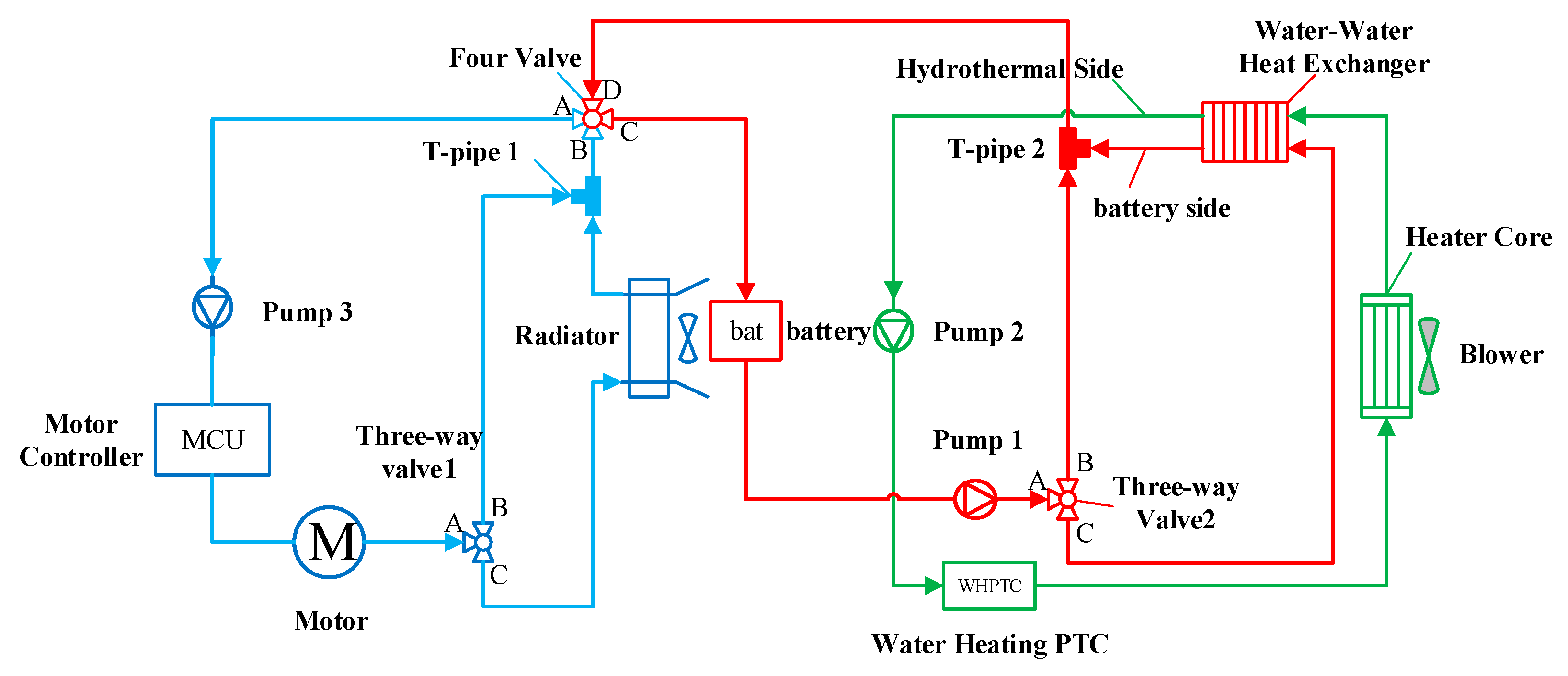
The integrated thermal management system is shown in
Figure 1, which includes three main thermal management system cycles: motor thermal cycle, battery thermal cycle, and cabin heating cycle. The motor thermal cycle includes a motor, MCU, and a pump. By controlling three-way valve 1, the switching of the internal and external cycles is achieved. For example, the motor coolant flows through the AB port of the three-way valve 1, which can achieve an internal cycle and quickly raise the coolant temperature; the motor coolant flows through the AC port of the three-way valve 1, achieving an external cycle which can fully utilize the radiator to cool the motor or battery. The battery thermal cycle includes a water-water heat exchanger and a pump, where the heat exchanger is the node between the battery cycle and the cabin heating cycle, using the PTC heater to heat the battery; By controlling three-way valve 2, the battery coolant flows from A to C, the heat exchanger can be used to exchange heat with the PTC heater. The battery coolant flows through the AB port of the three-way valve 2, thereby stopping the battery cycle heating. As this paper mainly focuses on the heating function of batteries, the air conditioning refrigeration circuit is not included in this structure. The cabin heating cycle includes a pump, a PTC heater, heater core, and blower. The PTC heater is used to provide heat to the cabin through the heating core. In addition, when the four-way valves AB and CD are connected, the motor thermal cycle and the battery thermal cycle are independent of each other. When the four-way valve AD and BC are connected, the motor thermal cycle and battery thermal cycle are connected in series, which can use the heat from the motor to heat the battery or use the radiator to cool the battery. According to the heating/cooling requirements of the motor, battery, and cabin, the integrated thermal management system scheme has ten operating modes, as shown in
Table 1. In addition, the operating state of the main components for each operating mode is shown in
Table 2.
2.2. Battery model
Compared with the battery first-order RC and electrochemical models, the Rint model requires fewer parameters and is faster to compute [
23,
24]. As shown in
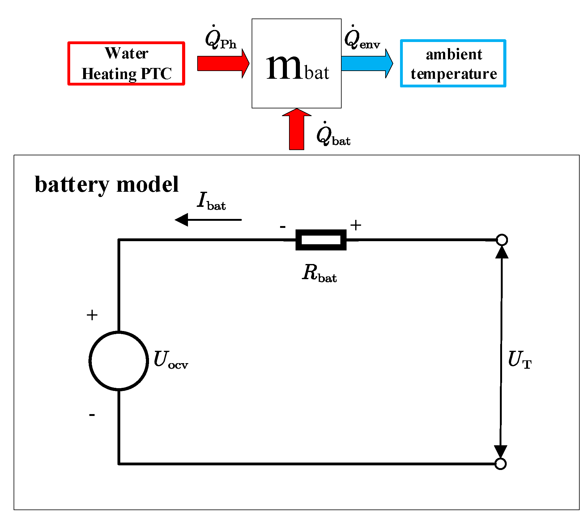
Figure 2, to simplify the model, the battery Rint model is considered in this paper (see
Table 3 for the main parameters). The battery pack is assumed to be a mass block with uniform temperature and consists only of an open-circuit voltage source and internal resistance. Therefore, the battery terminal voltage during charging is calculated as:
where
is the battery pack terminal voltage,
is the battery pack open circuit voltage,
is the battery pack charging current (battery charging current is positive),
is the battery pack charging internal resistance.
Li-ion batteries’ internal resistance and open-circuit voltage are nonlinear functions of temperature and SOC, and the temperature and SOC of the battery are correlated with battery charging-preheating costs. Therefore, modeling of battery heat production and charging is required. The thermodynamic processes of the battery pack in the low-temperature charging-preheating scenario mainly include:
heat production by the internal resistance of the battery;
effective heating by the PTC heater;
heat transfer between the battery pack and the environment.
The effective heat transferred to the battery can be divided into two parts: one part is used for heating the battery mass block, and the other is dissipated into the environment. Thus, the battery heat balance equation is as follows:
where
is the heat-generating power of the battery pack,
is the effective power of the PTC heater,
is the heat exchange power between the battery pack and the environment,
is the specific heat capacity of the battery pack,
is the total mass of the battery pack,
is the average temperature of the battery pack.
Taking into account
,
, and
, the specific expression for Equation 2 is as follows :
where
is the electric power of the PTC heater,
is the cumulative heating efficiency of the PTC heater and the water-water heat exchanger,
is the heat transfer coefficient of the battery pack,
is the heat exchange area of the battery pack,
is the ambient temperature.
The SOC of the battery during the charging process is related to the charging current, and its expression is as follows:
where
is the battery pack capacity.
Table 3.
Main parameters of battery pack.
Table 3.
Main parameters of battery pack.
| Parameters |
Value |
Unit |
| Total mass |
240 |
kg |
| Specific heat capacity |
1140 |
j/(kg·k) |
| Capacity |
163 |
A·h |
| Heat exchange area |
0.7474 |
m2
|
| Heat transfer coefficient |
10 |
W/(m2 ·K) |
| Cumulative heating efficiency |
0.9 |
— |
| Series-parallel connection |
96S1P |
— |
Figure 2.
Schematic diagram of the battery model.
Figure 2.
Schematic diagram of the battery model.
3. Battery AC Charge-Preheat Strategy
3.1. Optimal control modeling
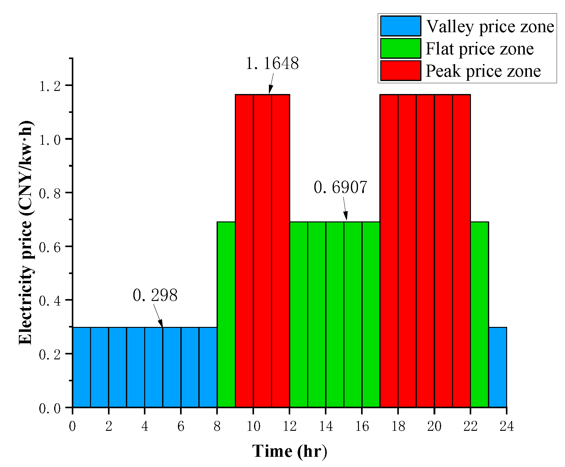
The main objective of this paper is to reasonably utilize grid energy from charging stations to charge and preheat pure electric vehicle batteries. The aim is to guarantee that the batteries attain the desired state of charge and the temperature for the user’s target departure time while minimizing the overall energy consumption cost from the grid. The working conditions of time-of-use electricity price are fixed, mainly including valley, flat, and peak price zones, as shown in
Figure 3. Considering that battery temperature
and SOC can characterize the current state of the battery, they are selected as state variables with the following expressions:
The charging current and the electric power of the PTC heater are selected as control variables, i.e. .
For computer solving, dynamic programming requires discretization of the state system. Equations 3 and 4 provide the discrete expressions for battery SOC and temperature, respectively:
Further, the state transfer equation of the system can be derived as follows:
where
and
are the state variables at the step of
k and (
k+1) respectively,
are the control variable at the step of
k ,
is the system state transition equation function, which is expressed as follows:
The control variables can be solved analytically based on the state transfer equation, which has the following expression:
Dynamic programming to solve the cost optimization problem under time-of-use electricity price requires solving the optimal control sequence when the objective function is minimized, and the objective function expression is:
where
is the transient transfer cost of the step
k ,
is the total cost of the first
N steps.
Considering mainly the electricity cost
consumed by charging the battery and the electricity cost
consumed by the PTC heater to preheat the battery, the transient transfer cost expression for the step of
k is as follows:
where
is the electricity price at the step of
k.
Considering the thermal safety during the battery charging-preheating process and the power limitations of the PTC heater, the following constraints are imposed mainly on the battery SOC, the battery temperature
, the AC charging current
, and the power of the PTC heater
.
where
is the initial SOC of the battery.
The initial temperature of the battery pack is the ambient temperature, and the user can set the target temperature and SOC under the reserved departure time. Considering the suitable working temperature range of Li-ion batteries is 15℃~35℃[
25,
26], the target temperature is set to 25℃, and the target SOC is set to 95%. The AC charging current and power of the PTC heater are adjusted according to the user’s target departure time and time-of-use electricity price, which not only meets the user’s charging-preheating demand but also reduces the user’s cost.
where
is the target SOC of the battery,
is the target temperature of the battery.
3.2. Dynamic programming solution
Dynamic programming algorithms are widely used in hybrid vehicle energy management systems to obtain global optimal control strategies for given driving cycles[
27,
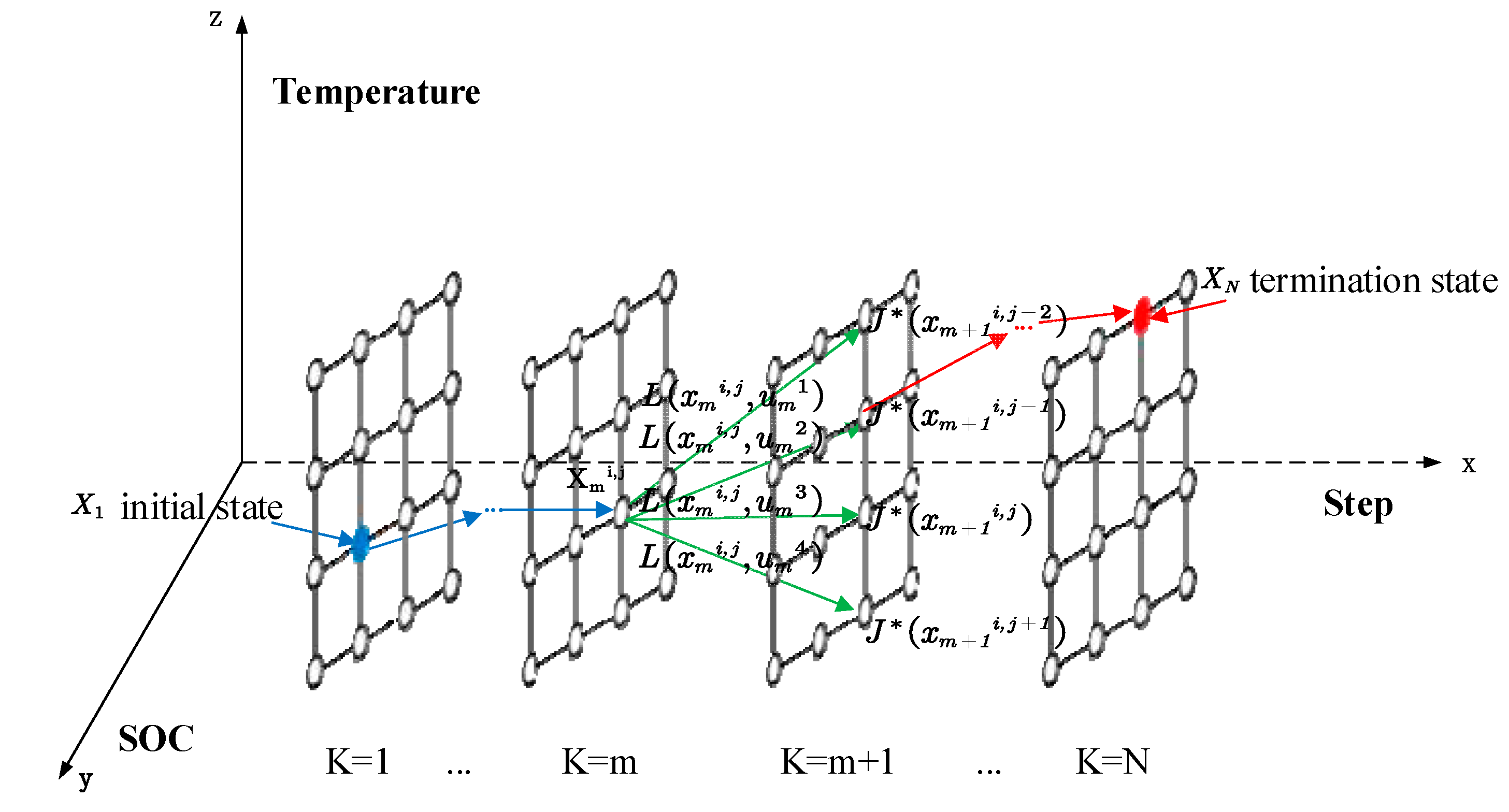
28]. The algorithm can convert a multi-stage decision-making problem into a series of single-stage decision-making problems, which are gradually solved inversely from back to front according to the state transfer equation. As shown in
Figure 4, the battery’s initial and termination states are fixed, and the user’s target departure time is set to
. The state variables and time domain are discretized, and the discrete state mesh shown in
Figure 4 can be obtained. Among them, the simulation step
is set to 600s, and the number of discrete grids in the time domain is
. The number of discrete grids for battery temperature and SOC is 201, and the discretization accuracies of the battery temperature and SOC are 0.2736℃ and 0.0037, respectively. The specific solution flow of dynamic programming is as follows:
Calculate the cost at the termination time :
Calculate theremaining cost
. According to equation (10), the control variables
and
required to transfer from state
to
can be solved directly, and thus the instantaneous transfer cost
between these two states can be solved. Therefore, the expression for the remaining cost is as follows:
where
represents the state at the position in the grid (i , j) at the
k=m step,
represents the No.q control variable of
at the
k=m step,
is the minimum remaining cost of
at the
k=m+1 step,
is the remaining cost of state
to terminate state with input control
at the
k=m step.
Calculate the minimum remaining cost at the
k=m step.
Calculate the optimal control sequence at the k=m step.
Store the optimal control sequence and the minimum remaining cost value for each step and repeat steps b to d until the computation ends at k=1 step, terminating the backward iterative process.
Reproduce the control variables of the inverse solution positively.
Figure 4.
Principle diagram of the dynamic programming algorithm.
Figure 4.
Principle diagram of the dynamic programming algorithm.
4. Results and discussion
4.1. Conventional preheating strategy
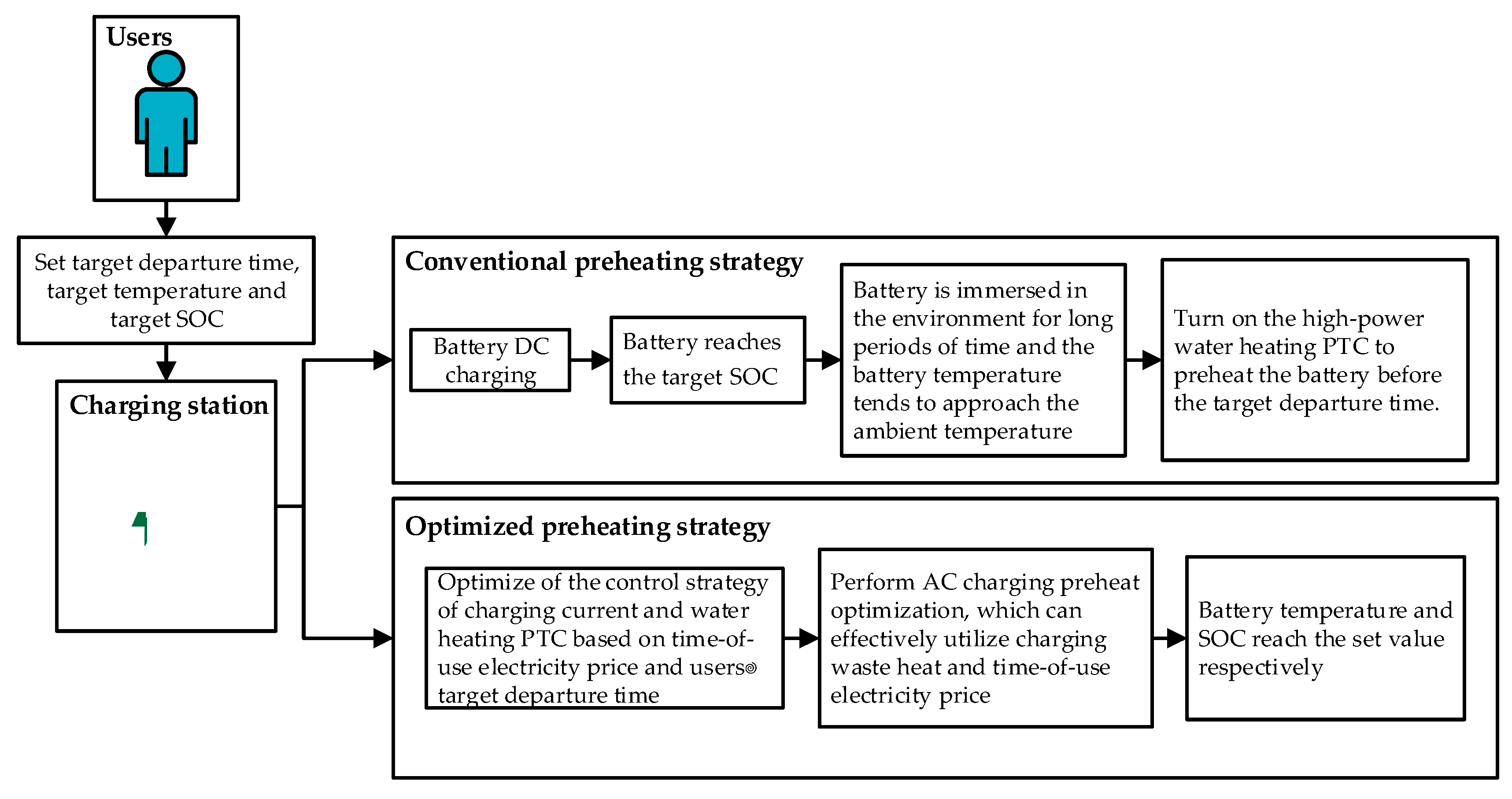
As shown in
Figure 5, most electric vehicle owners choose to charge at night. The battery is left in the environment for a long time after charging, and the battery temperature becomes the same as the ambient temperature. Before traveling, the high-power PTC heater is turned on to heat the battery to the target temperature. The conventional preheating strategy does not utilize time-of-use electricity price and charging waste heat. In addition, the grid cost consumed by the PTC heater is closely related to the user’s travel time. For example, when the user travels in the peak price zone, the grid cost consumed by the PTC heater is much higher than that in the valley price zone.
When the battery remains in the environment after charging for a long time, the heat produced by the charging internal resistance in the conventional preheating strategy is negligible (Assuming
is set to 0), and the temperature rise function of the battery is derived from Equation (3):
The battery preheating target temperature is set to 25°C. The maximum power of the PTC heater is 7000 W. Further, according to the above equation, the preheating time and energy consumption required for the conventional preheating strategy at different ambient temperatures can be found. The results are shown in
Table 4.
The cost of the conventional preheating strategy is solved by integrating the grid energy consumed to heat the battery during the preheating time and the time-of-use electricity price for that period:
where
is the cost of the conventional preheating strategy,
is the user’s target departure time,
is the preheating time for the conventional preheating strategy,
is the time-of-use electricity price function,
is the maximum power of the PTC heater.
The cost-saving rate can be calculated based on the cost of the optimized strategy and the cost of the conventional preheating strategy with the following expression.
where
is the cost-saving rate,
is the cost of the optimized preheating strategy.
Table 4.
Preheating time and energy consumption under different ambient temperatures.
Table 4.
Preheating time and energy consumption under different ambient temperatures.
| Ambient temperature/°C |
Preheating time/s |
Energy consumption/(kw·h) |
| -20 |
2008.4 |
3.91 |
| -15 |
1779.7 |
3.46 |
| -10 |
1552.5 |
3.02 |
| -5 |
1326.6 |
2.58 |
| 0 |
1102.1 |
2.14 |
Figure 5.
Flowchart of conventional preheating strategy and optimized preheating strategy.
Figure 5.
Flowchart of conventional preheating strategy and optimized preheating strategy.
4.2. Comparison and analysis of simulation results
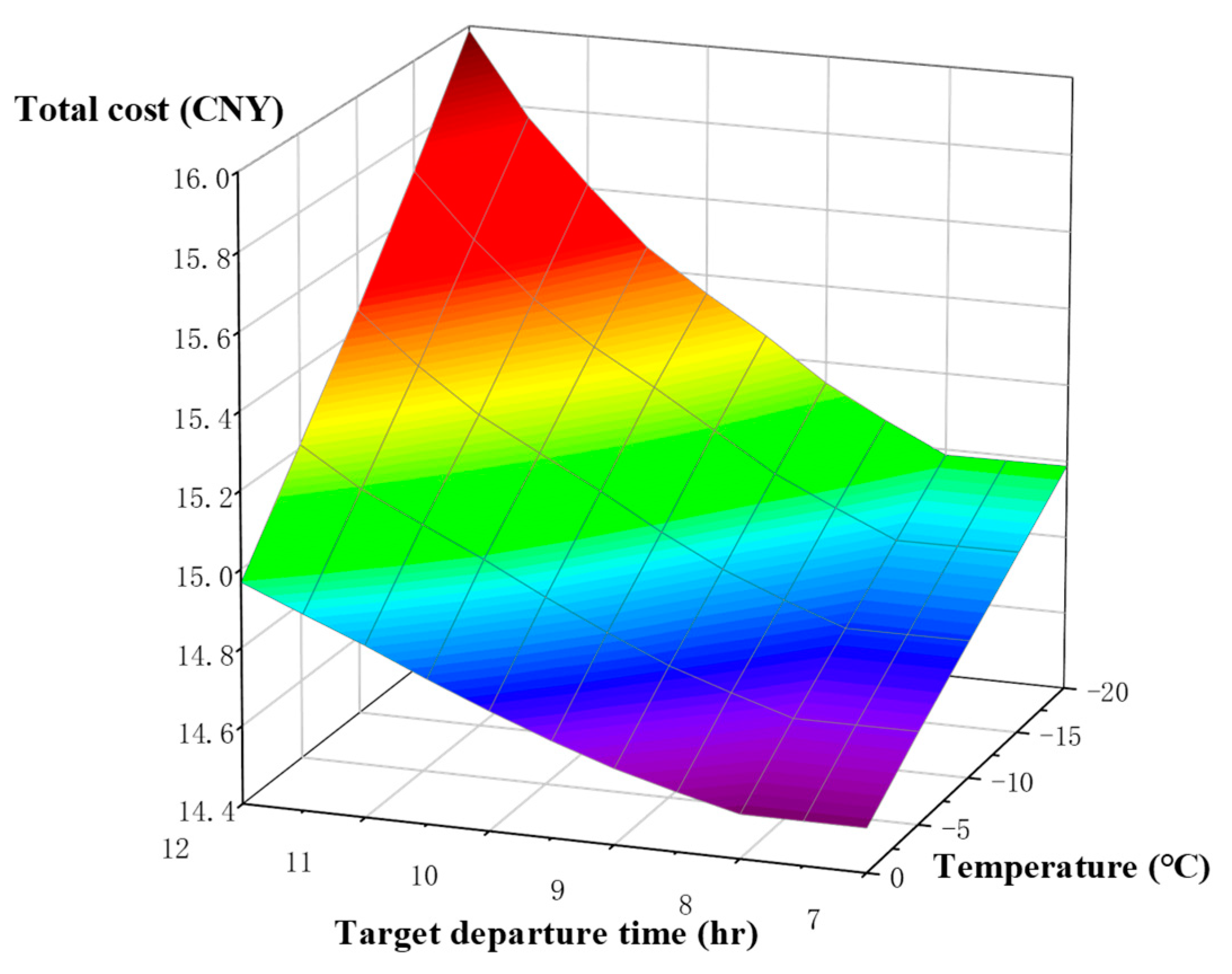
The optimized total cost increases as the ambient temperature decreases and the user’s target departure time increases, as shown in
Figure 6. This is because colder temperatures require more electrical energy to heat the battery to the target temperature. If the target departure time is delayed, the heat generated by preheating the battery during the valley price period will gradually dissipate. For the battery to reach the set temperature value, it needs to increase the turn-on time of the PTC heater in the flat and peak zones, so the total cost consumption is higher.
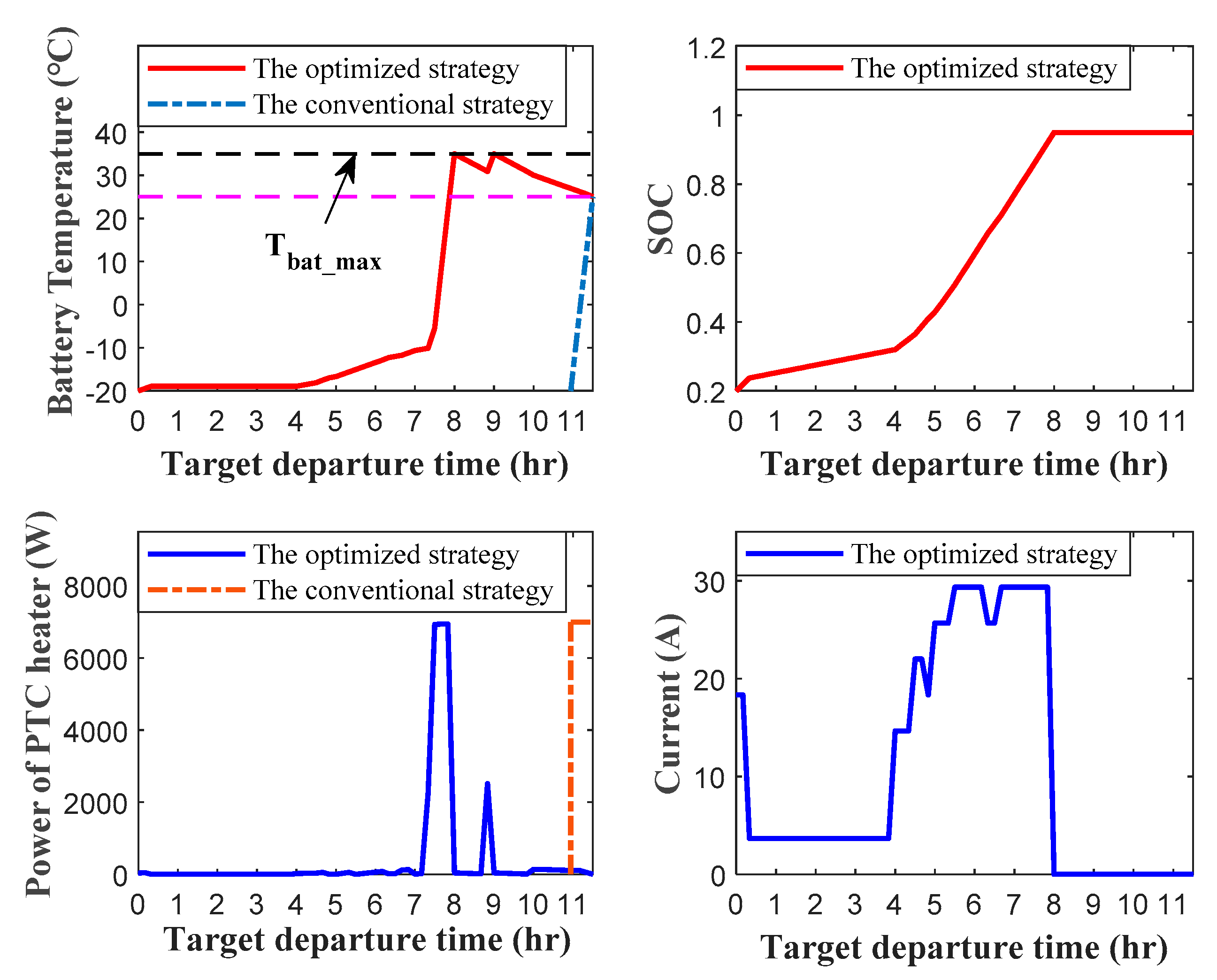
The result of the optimized control strategy, when the ambient temperature is -20℃ and the user’s target departure time is 11:30, is shown in
Figure 7. During the AC charging process, the battery pack reaches the set target SOC at 8:00, and the charging current is 0 after 8:00. This is because charging with a large capacity of Li-ion batteries consumes high electrical energy, and charging in the valley-price zone is more economical. From the curve of the battery temperature, it can be seen that the rise of the battery temperature before 8:00 is mainly due to the heat generated by the internal resistance of the battery during the charging process and the heat production of the PTC heater in the valley price zone. To ensure that the battery temperature reaches 25°C at 11:30 with the lowest cost, the optimized control strategy turns on the high-power PTC heater in the valley price zone to heat the battery to the set upper-temperature threshold
, then cools it down in the ambient temperature, and continues to turn on the PTC heater in the flat price zone to heat the battery to
, and repeats the cooling down process afterward. Finally, turning on the PTC heater with small power in the peak price zone makes the battery reach 25°C under the combined effect of ambient temperature and the PTC heater. At this time, the power consumed by preheating the battery is mainly concentrated in the valley and flat price zones. In contrast, the conventional preheating strategy uses the PTC heater with a big power to heat the battery before 11:30, concentrating all the power consumption in the peak price area.
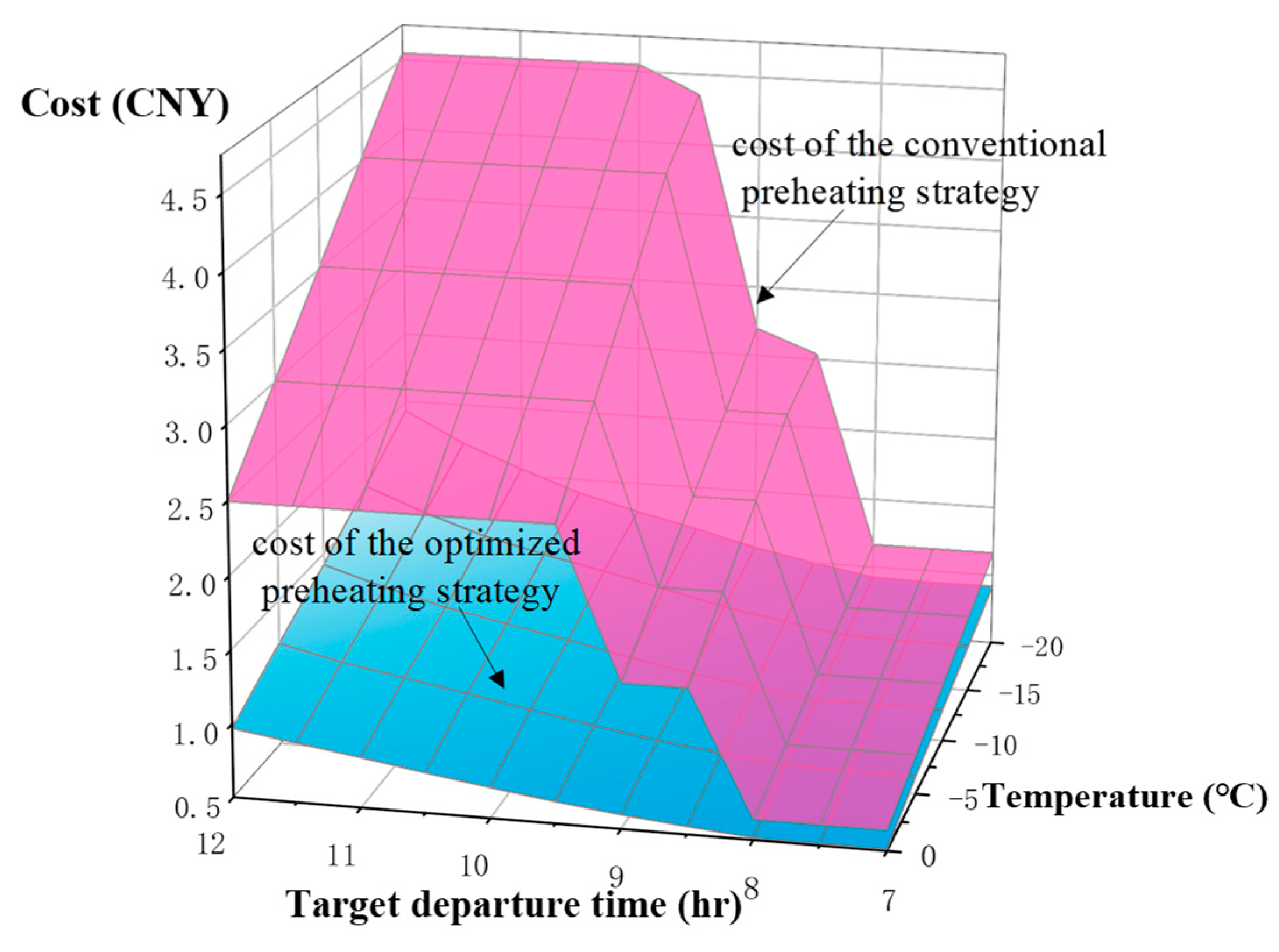
The comparison of the grid cost consumed by the conventional preheating strategy and the optimized strategy is shown in
Figure 8. From equation (20), the cost of the conventional preheating strategy is mainly affected by the electricity price under the user’s target traveling time and the energy consumption of the battery preheating. Under the same ambient temperature, the trend of the cost of the conventional preheating strategy over time is consistent with the trend of the time-of-use electricity price over time. That is, the cost of the conventional preheating strategy remains constant in each region of the valley price zone (0:00 to 8:00), the flat price zone (8:00 to 9:00), and the peak price zone (9:00 to 12:00), but the cost of preheating decreases sequentially between different regions of the time-of-use electricity price. The preheating cost of the optimized strategy follows the same trend as the optimized strategy’s total cost, increasing with decreasing ambient temperature and increasing target departure times.
The grid cost savings of the optimized strategy compared to the conventional preheating strategy are shown in
Table 5. Under the ambient temperature of -15°C to 0°C, the optimized strategy generally saves the highest cost when the user’s target travel time is 9:30. The highest cost savings is 3.26 CNY at -20°C. Under the ambient temperature of -20°C to 0°C, the cost savings are generally lowest when the user’s target departure time is set to 8:00, and there is little difference in the cost savings before 8:00. This is because the valley price zones are all before 8:00, and the differences in charging strategies between different target departure times lead to small changes in the turn-on time of the PTC heater.
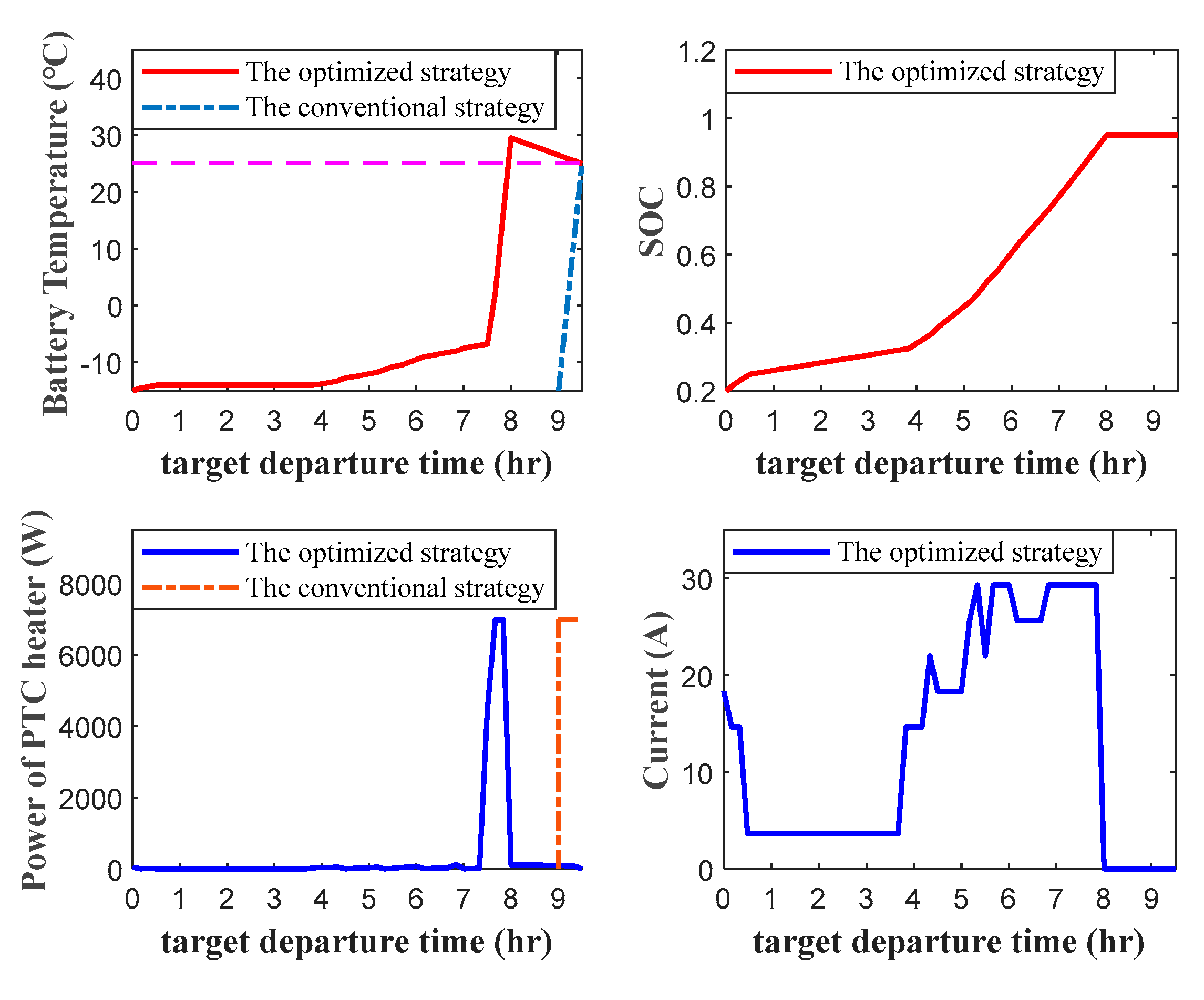
The results of the optimized control strategy are shown in
Figure 9 when the ambient temperature is -15°C and the user’s target departure time is 9:30. At this time, the energy consumption of the PTC heater is mainly concentrated in the valley price zone. After the battery temperature increases to 29.5°C, the ambient heat dissipation begins and the battery temperature eventually decreases to 25°C. The heating moment interval of the conventional preheating strategy is all in the flat price zone. Thus, the cost savings are generally higher when the target departure time is 9:30.
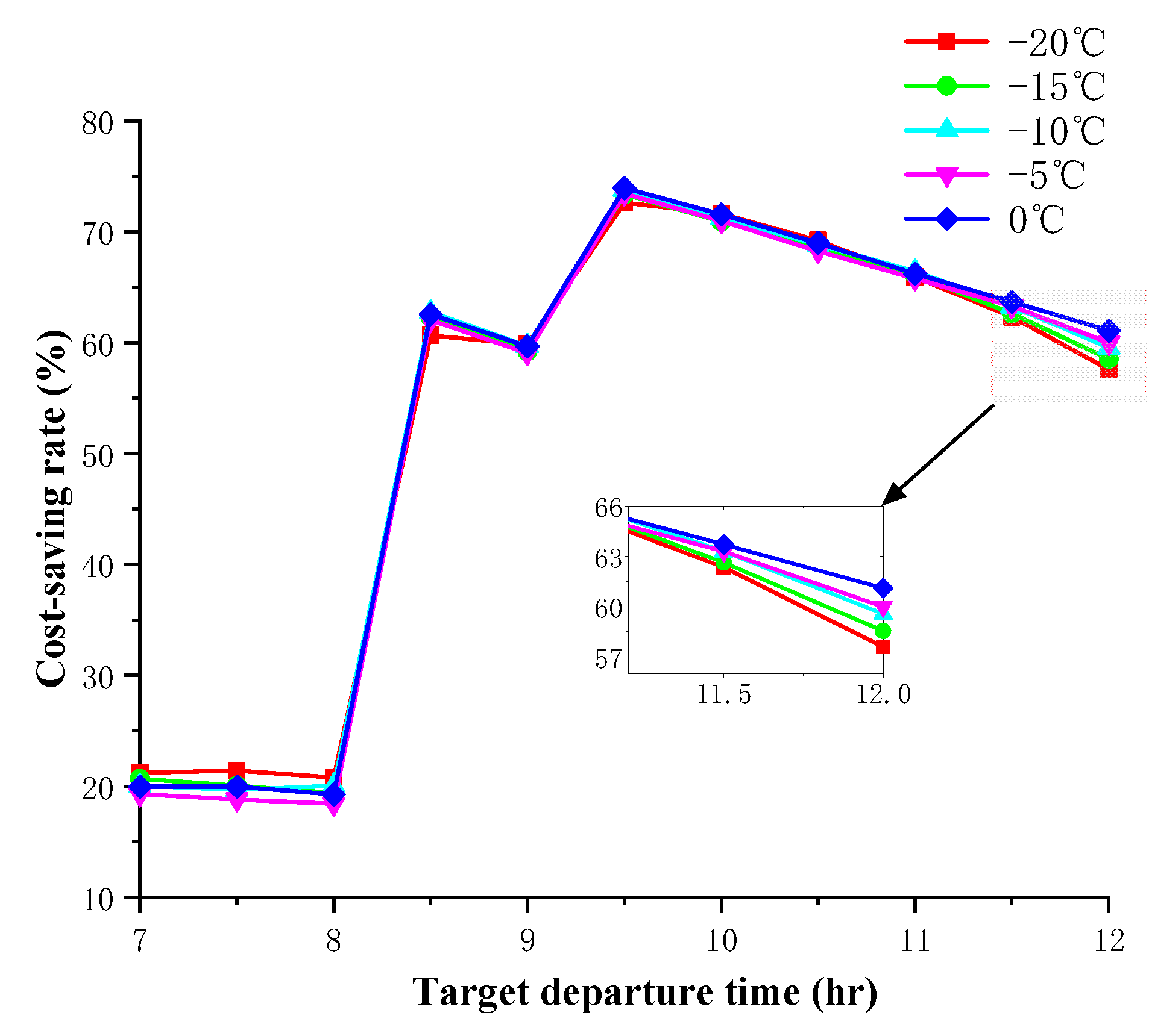
The optimized cost-saving rate at different ambient temperatures is shown in
Figure 10. The cost-saving rate ranges from 18.41% to 73.96%. Under the ambient temperature of -20 °C to 0°C, the cost-saving rate before 8:00 is about 20%. This is because the conventional preheating strategy relies solely on the PTC heater to preheat the battery to the target temperature. In contrast, the appointment charging and battery preheating are performed simultaneously, as proposed in this paper. The internal resistance heat production of the battery during the charging process reduces the turn-on time of the PTC heater, resulting in a higher cost utilization of the optimized strategy than the conventional preheating strategy.
Under the ambient temperature of -20 °C to 0°C, the cost savings after 8:00 are more significant than those before 8:00. This is because the optimized control strategy makes full use of the valley price zone of the time-of-use electricity price. In contrast, most of the turn-on periods of the PTC heater in the conventional preheating strategy are concentrated in the flat or peak price zones.
5. Conclusions
In this paper, first build battery thermodynamic and SOC models based on the integrated thermal management system scheme. Aiming at the scenario of pure electric vehicles using charging piles for AC charging and battery preheating, a method based on time-of-use electricity price for optimizing AC charging current and the control strategy of the PTC heater is proposed. The effectiveness of the method on cost saving is also analyzed under different ambient temperatures and user’s target departure times.
The simulation results show that the optimized control strategy can make the battery reach the desired SOC and temperature at the target departure time with the lowest total cost. In addition, the optimized AC charging-preheating total cost increases with decreasing ambient temperature and increasing target travel moment. Compared with the conventional preheating strategy, the optimized battery preheating strategy can save up to 3.26 CNY at different ambient temperatures and users’ target departure times, and the cost-saving rate can reach 18.41% to 73.96%. Under -15℃~0℃, the cost utilization rate reaches the maximum value at 9:30, which can effectively utilize the grid energy in the valley price zone and reduce the effective turn-on time of the PTC heater in the flat price zone.
References
- Guo, R.; Li, L.; Sun, Z.; Xue, X. An integrated thermal management strategy for cabin and battery heating in range-extended electric vehicles under low-temperature conditions. Appl. Therm. Eng. 2023, 228, 120502:1-120502:25. [CrossRef]
- Wang, J.; Ruan, L. Performance investigation of integrated thermal management system based on a pumped two-phase cooling system for electric vehicles. J. Energy Storage 2023, 72, 107922:1-107922:12. [CrossRef]
- Ye, J.; Aldaher, A.Y.M.; Tan, G. Thermal performance analysis of 18,650 battery thermal management system integrated with liquid-cooling and air-cooling. J. Energy Storage 2023, 72, 108766:1-108766:10. [CrossRef]
- Dai, X.; Ping, P.; Kong, D.; Gao, X.; Zhang, Y.; Wang, G.; Peng, R. Heat transfer enhanced inorganic phase change material compositing carbon nanotubes for battery thermal management and thermal runaway propagation mitigation. J. Energy Chem. 2023, 89, 226–238. [Google Scholar] [CrossRef]
- Huang, Z.; Gao, Z.; Liu, Y.; Guan, K.; Lu, Y.; Zhou, F.; Jiang, F.; Peng, J. A low temperature preheating strategy with optimized fuzzy controller for lithium-ion batteries. J. Energy Storage 2022, 52, 104709:1-104709:13. [CrossRef]
- Zhang, C.; Huang, J.; Sun, W.; Xu, X.; Li, C.; Li, Y. Research on liquid preheating performance for battery thermal management of electric vehicles at low temperature. J. Energy Storage 2022, 55, 105497:1-105497:11. [CrossRef]
- Guan, K.; Huang, Z.; Liu, Y.; Gao, Z.; Li, H.; Jiang, F.; Peng, J. A state of charge-aware internal preheating strategy for Li-ion batteries at low temperatures. J. Energy Storage 2023, 72, 108585:1-108585:13. [CrossRef]
- Hu, Z.; Liu, F.; Chen, P.; Xie, C.; Huang, M.; Hu, S.; Lu, S. Experimental study on the mechanism of frequency-dependent heat in AC preheating of lithium-ion battery at low temperature. Appl. Therm. Eng. 2022, 214, 118860:1-118860:12. [CrossRef]
- Wu, X.; Cui, Z.; Chen, E.; Du, J. Capacity degradation minimization oriented optimization for the pulse preheating of lithium-ion batteries under low temperature. J. Energy Storage 2020, 31, 101746:1-101746:12. [CrossRef]
- Chen, S.; Zhang, G.; Wu, C.; Huang, W.; Xu, C.; Jin, C.; Wu, Y.; Jiang, Z.; Dai, H.; Feng, X.; et al. Multi-objective optimization design for a double-direction liquid heating system-based Cell-to-Chassis battery module. Int. J. Heat Mass Transf. 2022, 183, 122184:1-122184:15. [CrossRef]
- Qin, P.; Sun, J.; Yang, X.; Wang, Q. Battery thermal management system based on the forced-air convection: A review. eTransportation 2021, 7, 100097:1-100097:22. [CrossRef]
- Qin, P.; Liao, M.; Mei, W.; Sun, J.; Wang, Q. The experimental and numerical investigation on a hybrid battery thermal management system based on forced-air convection and internal finned structure. Appl. Therm. Eng. 2021, 195, 117212:1-117212:14. [CrossRef]
- Wang, Y.; Rao, Z.; Liu, S.; Li, X.; Li, H.; Xiong, R. Evaluating the performance of liquid immersing preheating system for Lithium-ion battery pack. Appl. Therm. Eng. 2021, 190, 116811:1-116811:10. [CrossRef]
- Huang, Y.-H.; Cheng, W.-L.; Zhao, R. Thermal management of Li-ion battery pack with the application of flexible form-stable composite phase change materials. Energy Conv. Manag. 2019, 182, 9–20. [Google Scholar] [CrossRef]
- Li, X.; Deng, J.; Huang, Q.; Zhang, G.; Chen, K.; Wang, Y. Experimental investigation on immersion liquid cooled battery thermal management system with phase change epoxy sealant. Chem. Eng. Sci. 2022, 264, 118089:1-118089:14. [CrossRef]
- Luo, M.; Ling, Z.; Zhang, Z.; Fang, X. A fast-response preheating system coupled with supercapacitor and electric conductive phase change materials for lithium-ion battery energy storage system at low temperatures. J. Energy Storage 2023, 73, 109255:1-109255:13. [CrossRef]
- Liu, X.; Hong, X.; Jiang, X.; Li, Y.; Xu, K. Novel approach for liquid-heating lithium-ion battery pack to shorten low temperature charge time. J. Energy Storage 2023, 68, 107507:1-107507:10. [CrossRef]
- Wang, T.; Wu, X.; Xu, S.; Hofmann, H.; Du, J.; Li, J.; Ouyang, M.; Song, Z. Performance of plug-in hybrid electric vehicle under low temperature condition and economy analysis of battery pre-heating. J. Power Sources 2018, 401, 245–254. [Google Scholar] [CrossRef]
- Ouyang, Q.; Fang, R.; Xu, G.; Liu, Y. User-involved charging control for lithium-ion batteries with economic cost optimization. Appl. Energy 2022, 314, 118878:1-118878:11. [CrossRef]
- Liang, S.; Zhu, B.; He, J.; He, S.; Ma, M. A pricing strategy for electric vehicle charging in residential areas considering the uncertainty of charging time and demand. Comput. Commun. 2023, 199, 153–167. [Google Scholar] [CrossRef]
- Tian, X.; Cheng, B.; Liu, H. V2G optimized power control strategy based on time-of-use electricity price and comprehensive load cost. Energy Rep. 2023, 10, 1467–1473. [Google Scholar] [CrossRef]
- Yin, W.; Wen, T.; Zhang, C. Cooperative optimal scheduling strategy of electric vehicles based on dynamic electricity price mechanism. Energy 2023, 263, 125627:1-125627:6. [CrossRef]
- Hou, J.; Xu, J.; Lin, C.; Jiang, D.; Mei, X. State of charge estimation for lithium-ion batteries based on battery model and data-driven fusion method. Energy 2024, 290, 130056:1-130056:9. [CrossRef]
- Wu, M.; Qin, L.; Wu, G. State of power estimation of power lithium-ion battery based on an equivalent circuit model. J. Energy Storage 2022, 51, 104538:1-104538:9. [CrossRef]
- Shahjalal, M.; Shams, T.; Islam, M.E.; Alam, W.; Modak, M.; Hossain, S.B.; Ramadesigan, V.; Ahmed, M.R.; Ahmed, H.; Iqbal, A. A review of thermal management for Li-ion batteries: Prospects, challenges, and issues. J. Energy Storage 2021, 39, 102518:1-102518:18. [CrossRef]
- Liu, J.; Yadav, S.; Salman, M.; Chavan, S.; Kim, S.C. Review of thermal coupled battery models and parameter identification for lithium-ion battery heat generation in EV battery thermal management system. Int. J. Heat Mass Transf. 2024, 218, 124748:1-124748:17. [CrossRef]
- Wang, C.; Liu, F.; Tang, A.; Liu, R. A dynamic programming-optimized two-layer adaptive energy management strategy for electric vehicles considering driving pattern recognition. J. Energy Storage 2023, 70, 107924:1-107924:14. [CrossRef]
- Li, F.; Gao, L.; Zhang, Y.; Liu, Y. Hierarchical operation switch schedule algorithm for energy management strategy of hybrid electric vehicle using adaptive dynamic programming. Sustain. Energy Grids Netw. 2023, 35, 101107:1-101107:10. [CrossRef]
|
Disclaimer/Publisher’s Note: The statements, opinions and data contained in all publications are solely those of the individual author(s) and contributor(s) and not of MDPI and/or the editor(s). MDPI and/or the editor(s) disclaim responsibility for any injury to people or property resulting from any ideas, methods, instructions or products referred to in the content. |
© 2024 by the authors. Licensee MDPI, Basel, Switzerland. This article is an open access article distributed under the terms and conditions of the Creative Commons Attribution (CC BY) license (http://creativecommons.org/licenses/by/4.0/).
