INTRODUCTION
The extraction and fractionation of Natural Gas Liquids (NGL) play a crucial role in the energy industry, enabling the separation and recovery of valuable components from natural gas streams. To optimize the performance of NGL extraction and fractionation trains, a synergistic approach combining simulation analysis, advanced modification techniques, and vertical advancement has been proposed. This research aims to explore the latest advancements in these areas and their potential for elevating the performance of NGL extraction and fractionation trains..
Simulation analysis has emerged as a powerful tool for analyzing and optimizing the efficiency of NGL extraction processes (Johnson & Smith, 2018). By simulating the behavior of complex systems, it provides insights into the performance of various process configurations and enables the identification of bottlenecks or areas for improvement (Thompson & Williams, 2019). Furthermore, simulation analysis facilitates the evaluation of different operating conditions and can guide the design of more efficient NGL extraction units (Anderson, 2017).
Advanced modification techniques offer promising avenues for enhancing the efficiency of NGL fractionation trains. These techniques encompass a wide range of strategies, such as process intensification, heat integration, and improved equipment design (Davis & Johnson, 2018). By implementing advanced modifications, it is possible to increase the separation efficiency, reduce energy consumption, and optimize the overall performance of NGL fractionation trains (Perez et al., 2019).
Vertical advancement, another key aspect of this synergistic approach, focuses on the continuous improvement and development of NGL extraction technologies. This involves the integration of emerging technologies, novel materials, and innovative process configurations (Rodriguez et al., 2020). Vertical advancement aims to push the boundaries of NGL extraction by exploring new frontiers and overcoming current limitations (Thompson & Martinez, 2020).
The literature provides valuable insights into the synergistic approach mentioned above. Previous studies have examined the optimization of NGL extraction using simulation analysis (Adams et al., 2017) and the impact of advanced modification techniques on fractionation train performance (White et al., 2018). Additionally, vertical advancement strategies, such as the use of novel solvents and membrane technologies, have been investigated to enhance NGL extraction efficiency (Garcia & Davis, 2019).However, there is still a need for a comprehensive review that integrates simulation analysis, advanced modification techniques, and vertical advancement in the context of NGL extraction and fractionation trains. By analyzing and synthesizing the latest research findings, this study aims to bridge the existing knowledge gaps and provide valuable insights for industry practitioners and researchers.
In conclusion, this research will explore the synergistic approach of simulation analysis, advanced modification techniques, and vertical advancement to elevate the performance of NGL extraction and fractionation trains. By leveraging these advancements, it is anticipated that enhanced efficiency, reduced operational costs, and improved sustainability can be achieved in the extraction and fractionation of Natural Gas Liquids..
In this study, various heat pump systems and self-heat recuperation technology are compared to a traditional distillation column in order to evaluate their energy-saving potential for a depropanizer unit in a typical natural gas liquid (NGL) production facility. The comparison is conducted through steady-state simulations and cost-benefit analyses. The different distillation configurations explored in this study include VC (Vapor Compression), MVR (Mechanical Vapor Re-compression), TVR (Thermal Vapor Re-compression), BF (Binary Fluid), SHE (Self-Heat Exchanger), IHC (Internal Heat Coupling), SHR (Self-Heat Recuperation), and MSHR (Multi-Stage Heat Recuperation). By analyzing these various options, the study aims to identify the most efficient and cost-effective approach for energy savings in the depropanizer unit.
The aim of this research is to investigate and explore the potential of a synergistic approach combining simulation analysis, advanced modification techniques, and vertical advancement to elevate the performance of Natural Gas Liquid (NGL) extraction and fractionation trains. The research seeks to analyze and optimize the efficiency of NGL extraction processes through simulation analysis, implement advanced modification techniques to enhance the performance of NGL fractionation trains, and explore vertical advancement strategies to push the boundaries of NGL extraction technologies. By achieving these objectives, the research aims to contribute to the advancement of NGL extraction and fractionation practices, ultimately leading to improved efficiency, reduced operational costs, and enhanced sustainability in the energy industry.
The objectives of this research are as follows
To investigate and analyze the potential of heat pump aided distillation (HPAD) and self-heat recuperation technology (SHRT) in reducing energy consumption in traditional distillation systems.
To evaluate and compare the performance of different retrofit options, including vapor compression, mechanical vapor re-compression, thermal vapor re-compression, bottom flashing, side heat exchanger, intermediate heating and cooling, self-heat recuperative, and modified self-heat recuperative distillation.
To simulate and analyze the selected retrofit designs using Aspen HYSYS software, considering various criteria and parameters.
To determine the optimal retrofit design that achieves the highest energy cost reduction and operational efficiency for NGL fractionation trains.
To provide insights and recommendations for the industry to adopt cost-effective and energy-efficient solutions for NGL extraction and fractionation processes.
By achieving these objectives, the study aims to contribute to advancements in NGL extraction and fractionation technologies, ultimately leading to improved energy efficiency and cost savings in the industry
The deliverables of the research on "Elevating Natural Gas Liquid (NGL) Extraction and Fractionation Train Performance: A Synergistic Approach of Simulation Analysis, Advanced Modification, and Vertical Advancement" include:
1. Research report: A comprehensive document summarizing the study's findings, methodology, and recommendations. This can contribute to knowledge dissemination and further research in the field.
Aligning these deliverables with the United Nations Sustainable Development Goals (SDGs), the following connections can be made:
SDG 7: Affordable and Clean Energy: The research aims to enhance energy efficiency in NGL extraction and fractionation processes. By reducing energy consumption through advanced technologies and modifications, it contributes to achieving affordable and clean energy.
SDG 9: Industry, Innovation, and Infrastructure: The study explores innovative retrofit options and technological advancements for NGL fractionation trains. By promoting improved infrastructure and technological solutions, it aligns with SDG 9 objectives.
SDG 13: Climate Action: By reducing energy consumption, the research indirectly contributes to mitigating greenhouse gas emissions associated with NGL extraction and fractionation. This supports the goals of SDG 13, which focuses on climate action and combating climate change.
SDG 12: Responsible Consumption and Production: The study's aim to optimize energy use and reduce operational costs aligns with SDG 12. By promoting efficient resource utilization, it contributes to responsible consumption and production patterns.
Overall, the deliverables of the research on this topic have the potential to align with various SDGs, particularly SDG 7 (Affordable and Clean Energy), SDG 9 (Industry, Innovation, and Infrastructure), SDG 13 (Climate Action), and SDG 12 (Responsible Consumption and Production).
Simulation of the distillation.
The depropanizer unit and its advanced distillation options were modeled and simulated using the Aspen HYSYS V7.3 simulator. To accurately predict the vapor-liquid equilibrium for a wide range of operating conditions, particularly for light hydrocarbon mixtures, the Peng Robinson property package was selected as the equation of state.
In modern distillation systems, compressors or steam ejectors are employed to enhance the energy content of the streams. For all the simulated compressors, an adiabatic efficiency of 75 percent was anticipated. During the heat exchange process, all heat exchangers were designed to
With stand a minimum temperature of 5 degree Celsius and a pressure drop of 0.34 bar(5 psi).
1.1. Conventional distillation system
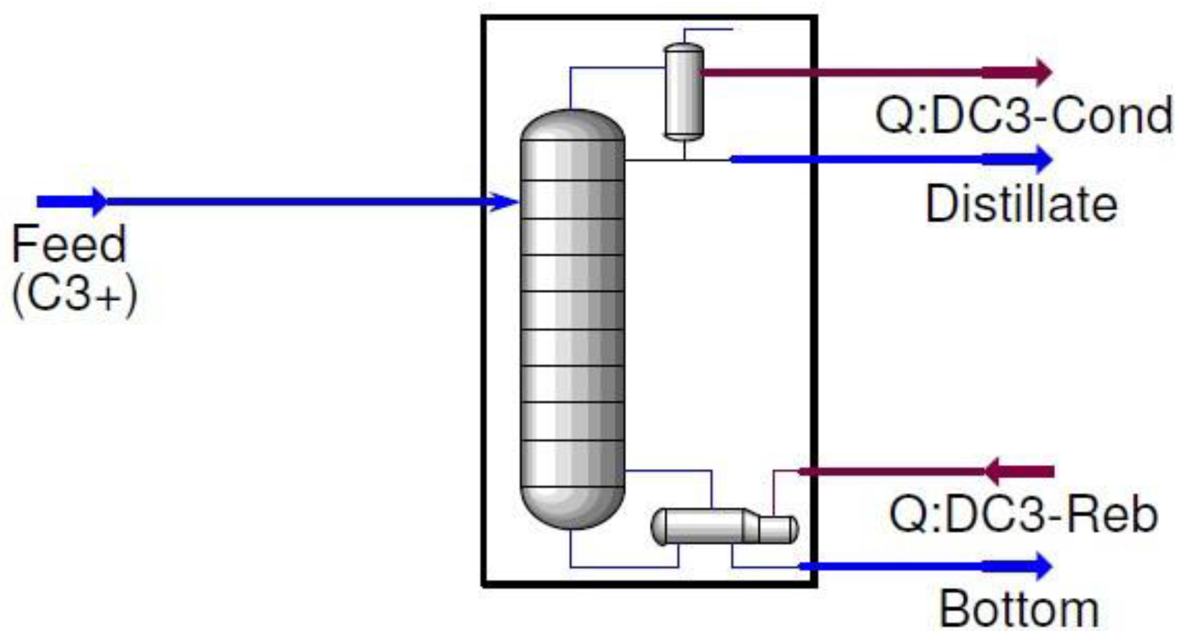
The case study focuses on a depropanizer at a natural gas processing plant in Nigeria. The study used Aspen HYSYS to create a flow diagram for the traditional distillation setup, which was used as a reference point for different strategies examined in the study. In this Traditional layout, the bottom product from a de-ethanizer in the plant is used as the feedstock for the depropanizer unit.
In the depropanizer column discussed in the study, the propane is separated as the distillate, while the remaining light hydrocarbons make up the bottom product.
Table 1 provides information on the composition, temperature, and pressure of the depropanizer feed, while
Table 2 presents the operating conditions and product parameters of the column. According to the simulation, the molar flow rates for the top and bottom product streams were 531.6 and 358.8 kmol/h, respectively. Throughout the analysis, the study maintained consistent feed conditions column settings, and product standard
Figure 1.
HYSYS flow diagram for the conventional distillation column.
Figure 1.
HYSYS flow diagram for the conventional distillation column.
Table 1 presents the feed conditions of the depropanizer column. It outlines the mole fraction of each component in the feed, as well as the total molar flow, temperature, and pressure. - The feed composition consists of various hydrocarbon components, including ethane (C2), propane (C3), i-butane (iC4), n-butane (nC4), i-pentane (iC5), n-pentane (nC5), n-hexane (nC6), n-heptane (nC7), n-octane (nC8), and n-nonane (nC9). - Each component is represented by its respective mole fraction, indicating the proportion of that component within the feed mixture. For example, propane (C3) has a mole fraction of 0.5959, indicating that it constitutes approximately 59.59% of the feed mixture. - The total molar flow of the feed is calculated to be 890.3 kmol/h, representing the overall quantity of material entering the depropanizer column. - The temperature of the feed is measured at 71.11°C, indicating the initial temperature at which the feed enters the column. - The pressure of the feed is recorded as 16.00 bar, representing the initial pressure at which the feed is introduced into the column. These feed conditions provide important information about the composition, quantity, temperature, and pressure of the incoming feed, which are crucial factors for the depropanizer column's operation and performance.
Table 2 showcases the column and product specifications, as well as the energy performance of the existing depropanizer. - The column consists of a total of 50 trays, divided into different categories. - The feed is introduced at tray locations labeled as Feed 1 and Feed 2, specifically at tray number 25. - The depropanizer demonstrates high efficiency in recovering propane (C3) at the top stream, with a mole fraction of 0.998. This indicates that it successfully captures 99.8% of the propane present in the feed. - Similarly, the depropanizer exhibits efficient recovery of butane (C4) at the bottom stream, with a mole fraction of 0.991. This signifies that it captures 99.1% of the butane present in the feed. - The top product stream from the depropanizer carries a total molar flow of 531.7 kmol/h, representing the amount of material leaving the column as the desired product. - On the other hand, the bottom product stream has a total molar flow of 358.9 kmol/h, indicating the quantity of material exiting the column as the byproduct. - The pressure of the top product stream is measured at 14.90 bar, while the pressure of the bottom product stream is slightly higher at 16.21 bar. These specifications provide valuable insights into the operational performance and output of the existing depropanizer column.
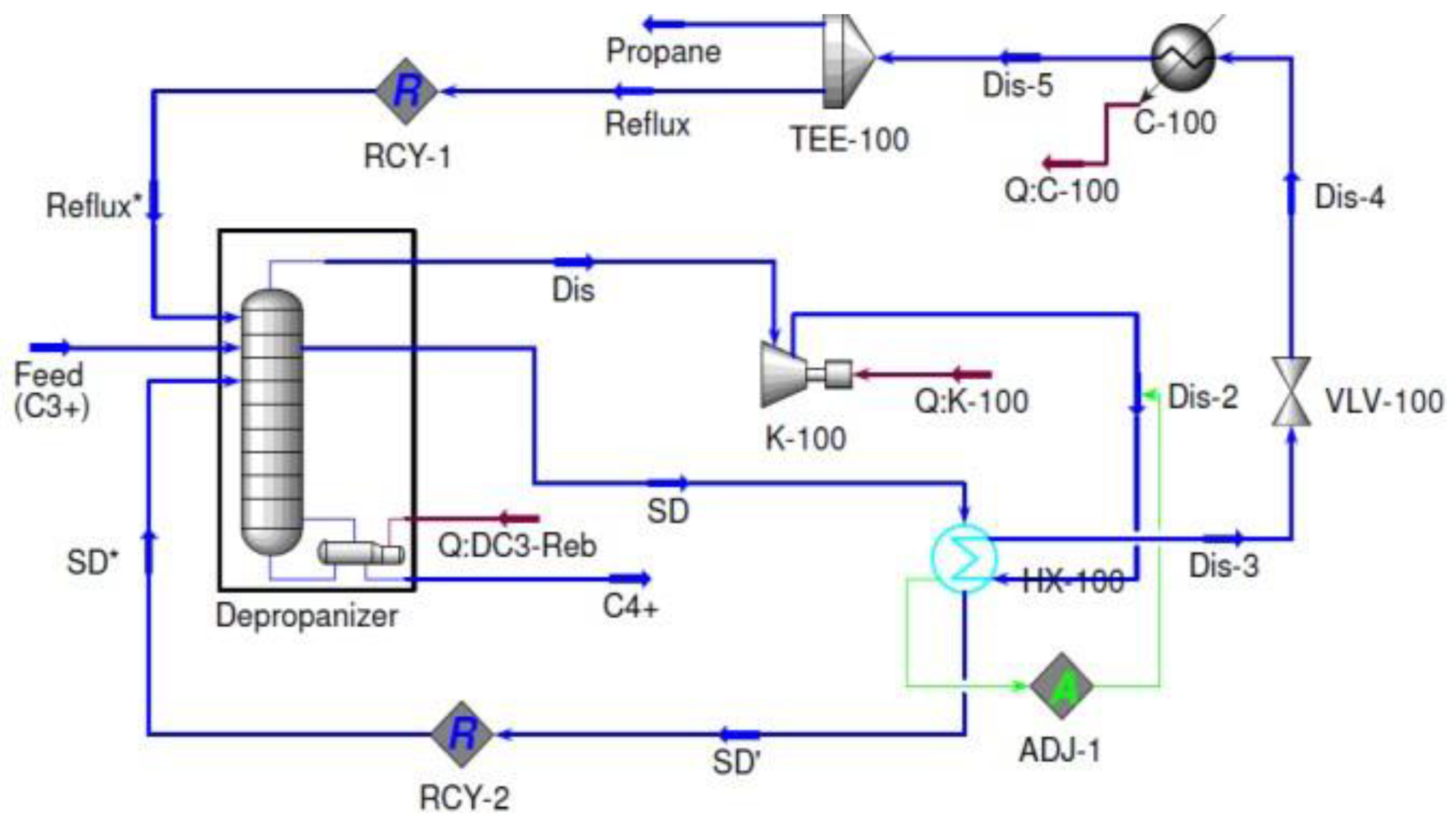
In the Vapor Compression (VC) system, a closed cycle heat pump configuration is employed, utilizing a refrigerant that circulates between the condenser and the reboiler. This system is designed to optimize energy efficiency.
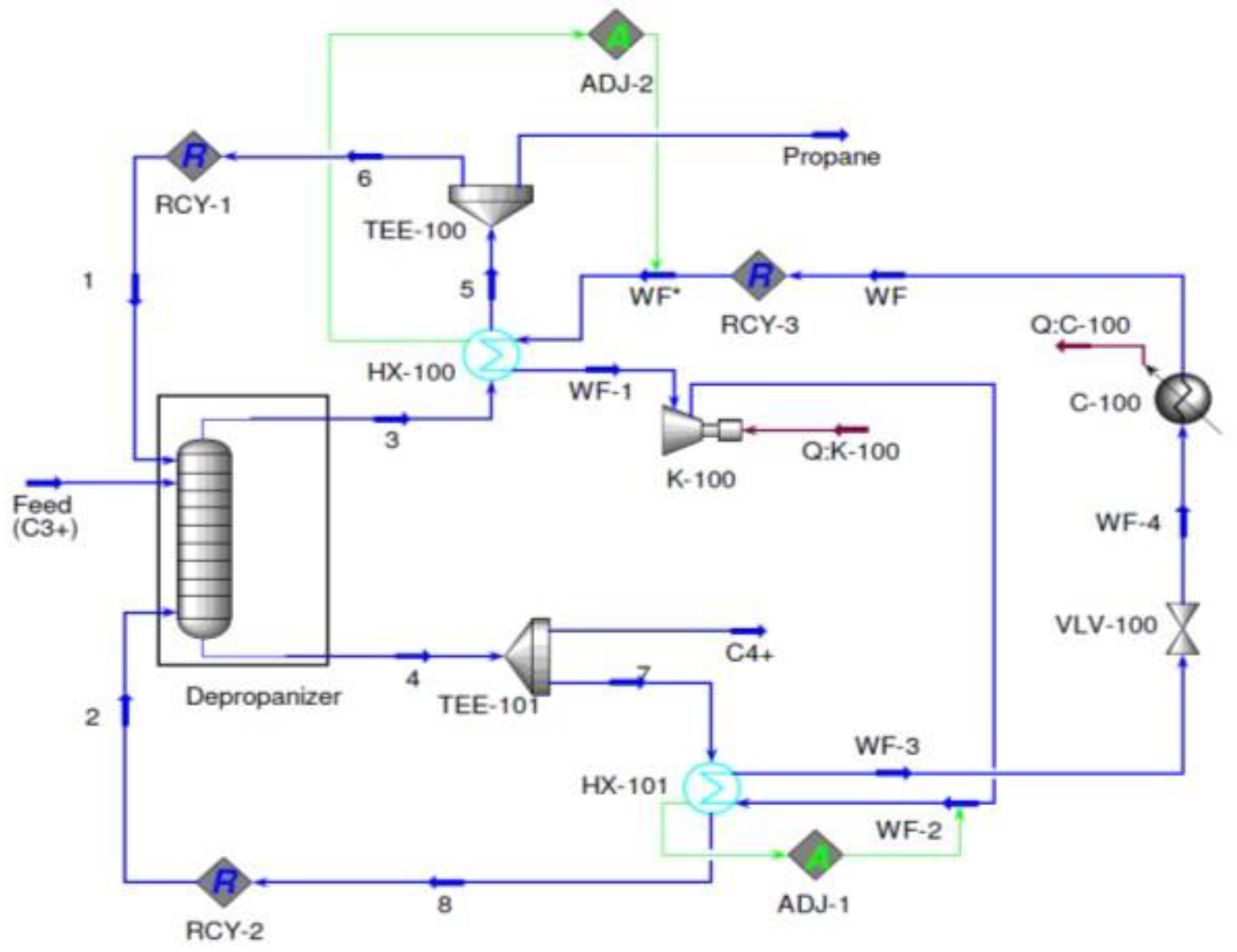
Figure 2 depicts the HYSYS flow diagram of the Vapor Compression system being investigated. In this specific study, propylene (R-1270) was chosen as the refrigerant [
9]. Within the system, the refrigerant initiates evaporation in the condenser HX-100, where it efficiently exchanges heat with the overhead product in the refrigeration cycle. Following vaporization, the refrigerant undergoes compression through the action of compressor K-100.
Following compression, the refrigerant is directed to reboiler HX-101 where it undergoes condensation. Subsequently, an expansion process takes place, resulting in a decrease in saturation temperature. Before being reintroduced into condenser HX-100, the partially condensed refrigerant stream requires additional cooling. To determine the necessary molar flow rate of the refrigerant, an adjustment unit is utilized at condenser HX-100.Furthermore, to optimize the performance and efficiency of the VC system, an additional adjustment unit is employed at the outlet of the compressor to regulate the pressure of the refrigerant stream. These adjustments play a crucial role in achieving optimal system operation.
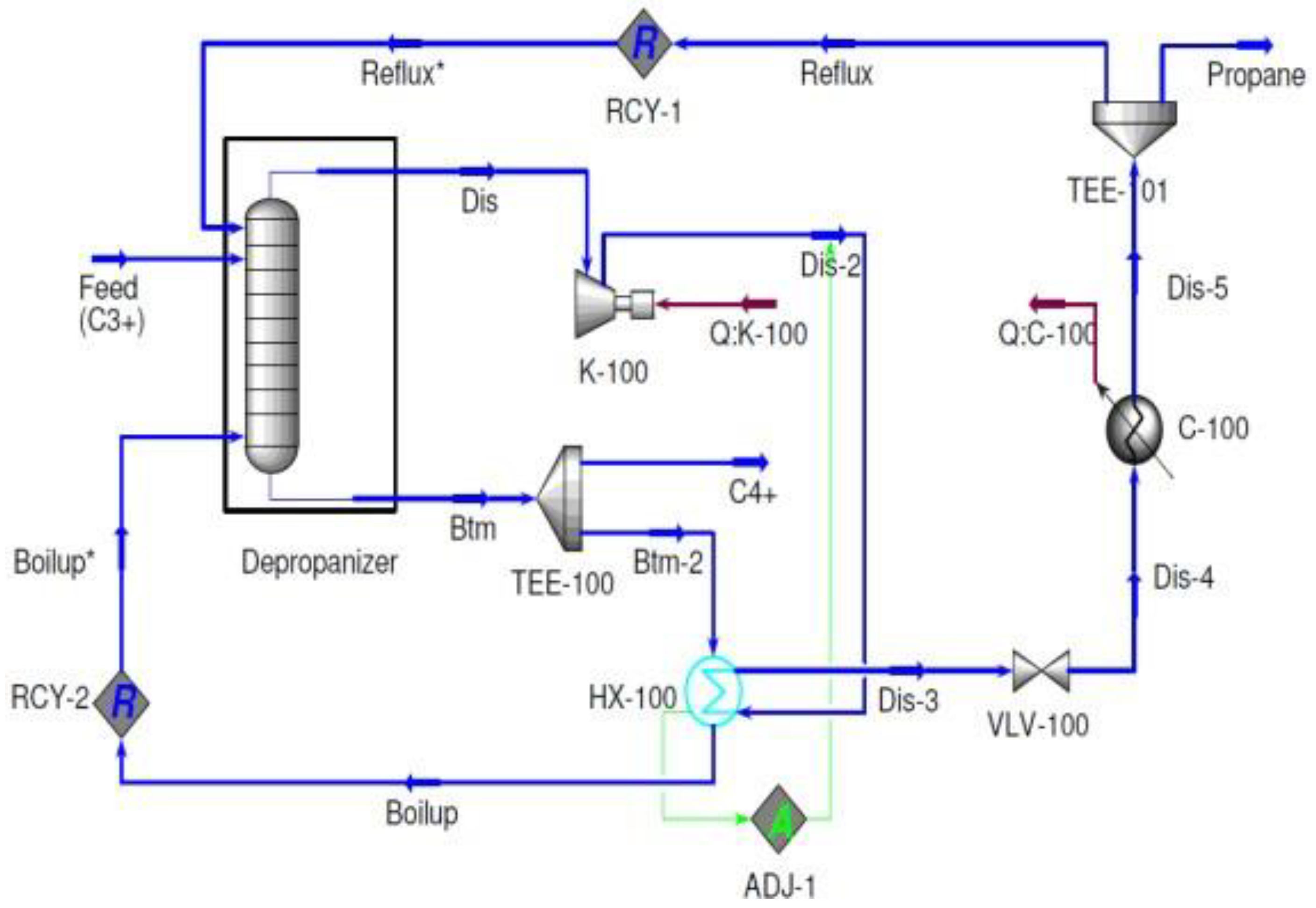
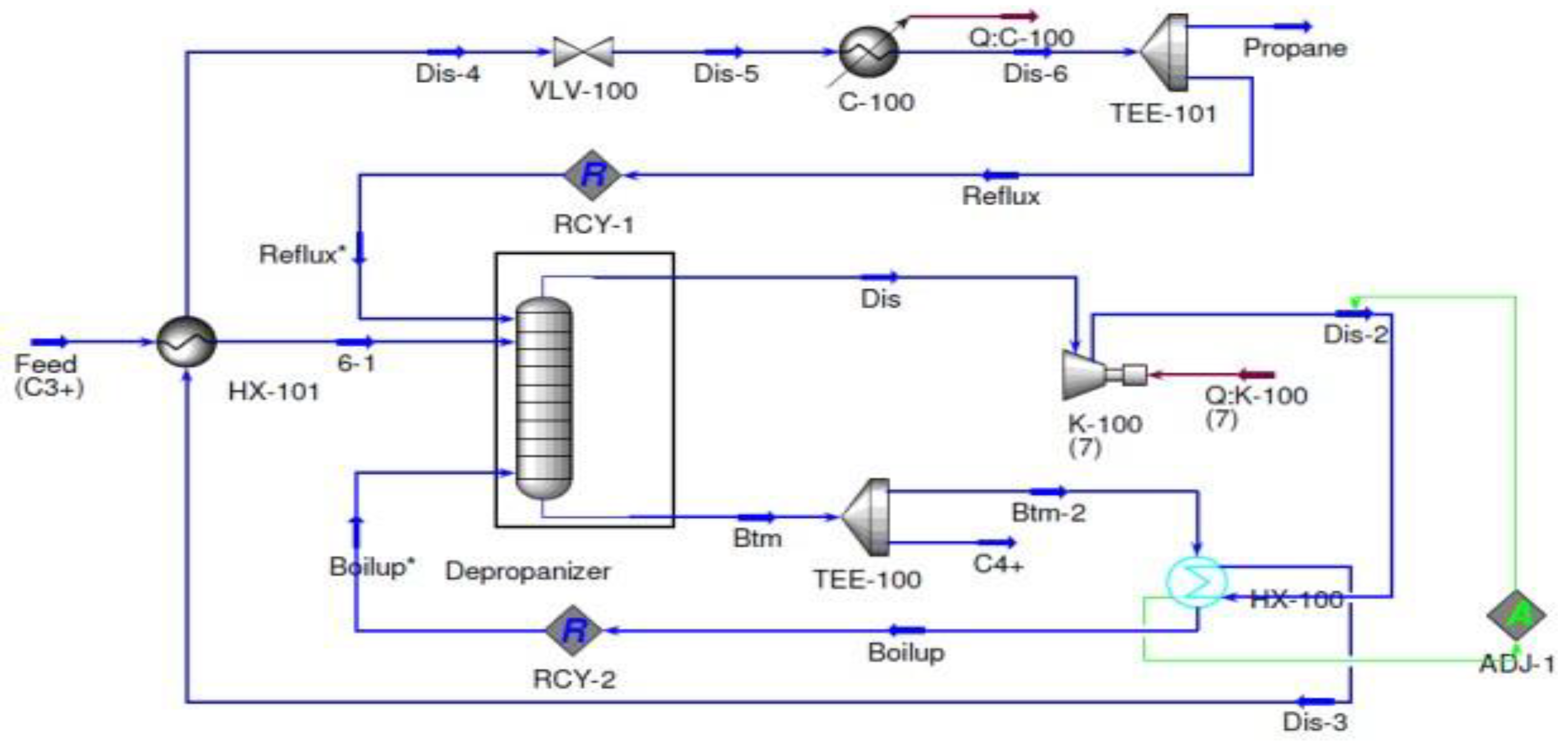
Figure 3 showcases the HYSYS flow diagram for the Mechanical Vapor Recompression (MVR) system, which is widely employed as an open cycle heat pump in distillation systems . In this system, one of the key steps involves the compression of the distillate using compressor K-100, resulting in a notable increase in its temperature. This process is instrumental in facilitating the overall functionality and efficiency of the MVR system within distillation operations.
In order to attain a minimum temperature approach of 5°C in heat exchanger HX-100, an adjustment unit is employed to calculate the pressure at the outlet of the compressor. This adjustment is crucial for optimizing the system's performance and guaranteeing the desired temperature approach is achieved in the heat exchanger. By carefully controlling the pressure, the system can efficiently maintain the desired temperature conditions, leading to improved overall operation.
Upon compression, the elevated temperature stream is guided through heat exchanger HX-100, where it engages in heat exchange with the bottom product stream. Within HX-100, the compressed stream is condensed, releasing the required heat to initiate the boiling process of the bottom product. Subsequently, the condensed stream undergoes expansion to reach the pressure at the column top, and it is further cooled to its saturation temperature before being recycled back to the column top or separated as the top product. This sequence of steps ensures efficient operation and optimal temperature conditions within the system.Following its vaporization, the stream is subsequently recirculated back to the bottom of the column at a later stage. This recirculation process plays a crucial role in optimizing energy utilization and further enhancing the overall efficiency of the distillation system. By reintroducing the vaporized stream, the system can achieve improved separation and maximize the energy efficiency of the distillation process.
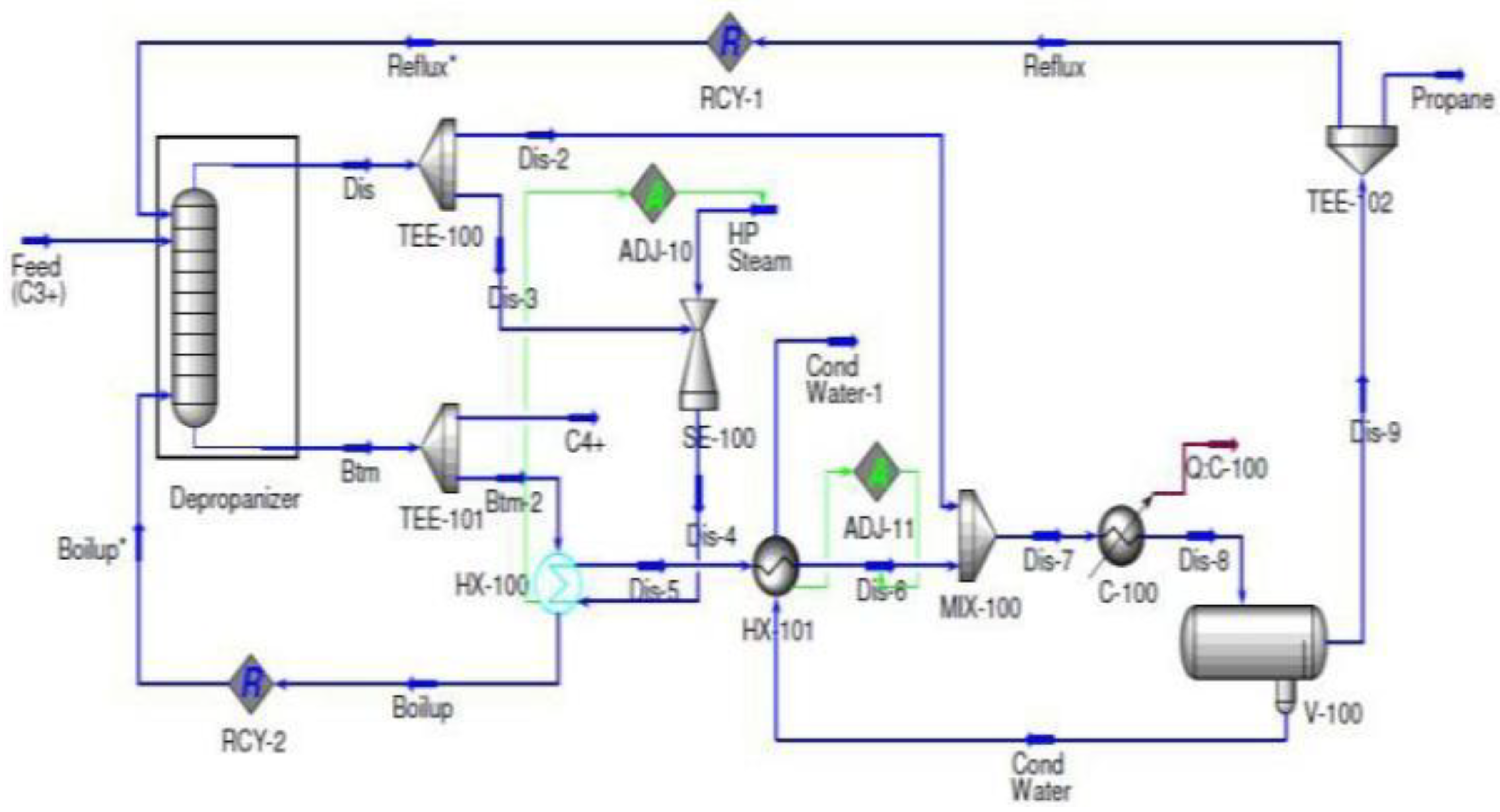
In the TVR (Thermo Vapor Recompression) system, similar to MVR, the distillate is compressed to leverage its latent heat for heat exchange with the bottom product from the column, as depicted in
Figure 4. However, in TVR, a different compression mechanism is employed. Instead of using a compressor like in MVR, a steam ejector is utilized.The ejector in the TVR system operates by utilizing steam as a saturated vapor at a pressure of 41 barg. This steam is effectively employed to compress the distillate, enabling the recovery of its latent heat and significantly enhancing the overall efficiency of the distillation process. By leveraging the latent heat of the distillate, the TVR system optimizes energy utilization and achieves improved separation efficiency, leading to enhanced performance and productivity.
In the TVR system, an adjustment unit is utilized in HX-100 to calculate the precise amount of steam needed by the steam ejector to achieve a minimum temperature approach of 5°C. This adjustment unit plays a crucial role in optimizing the system's performance and ensuring the desired temperature approach is achieved in the heat exchanger. The heat energy from the compressed stream is then utilized to facilitate the boiling process of the bottom product stream within HX-100. This interaction allows for efficient utilization of the heat energy from the compressed stream, effectively transferring it to the bottom product stream. Following this heat exchange, the condensed stream is recycled back to the column, completing the cycle. This process aids in maximizing energy usage and enhancing the overall efficiency of the distillation system.
In order to reach its saturation temperature, the partially condensed stream undergoes additional cooling through the utilization of heat exchanger HX-101 and cooler C-100. These cooling units work together to effectively bring the stream to its desired temperature. Following the cooling process, the water and propane mixture is then separated in the V-100 separator. This separation step is essential for optimizing the distillation system and ensuring the desired product purity is achieved. By effectively separating the components, the distillation system can recover pure propane, which is the desired end product. This separation process plays a vital role in maintaining the quality and purity of the final product, ensuring the distillation system operates at its optimal capacity.
Once the propane stream has been separated, it is further divided into two distinct streams: the end product and the reflux stream. The end product stream consists of the desired purified propane, which can be collected and utilized for various applications. This stream represents the final product of the distillation process and is typically of high quality and purity. On the other hand, the reflux stream is a portion of the separated propane stream that is recycled back into the distillation column. This reflux stream serves a crucial role in the distillation process by providing a liquid phase that descends through the column, aiding in the separation and purification of the desired components. By separating the propane stream into these two streams, the distillation system can effectively control the purity of the end product while maintaining optimal operating conditions within the column.
In
Figure 5, the BF (bottoms fractionation) system is designed as an open system, utilizing the bottom product from the column as a refrigerant [
14]. The product extracted from the column is divided into two separate streams: the final bottom product and the recycled stream, as illustrated in the figure. The recycled stream is pressurized to match the saturation temperature of the distillate before being reintroduced back into the column. This pressurization process ensures that the recycled stream is at the appropriate pressure and temperature to effectively contribute to the distillation process within the column. By utilizing the bottom product as a refrigerant and incorporating the recycled stream, the BF system optimizes energy usage and enhances the efficiency of the distillation process. This design enables effective separation and purification of the desired components, resulting in the production of the final bottom product while maintaining optimal operating conditions within the system.
To achieve a minimum temperature difference of 5°C, the pressure of the valve output is adjusted in the HX-100 unit. This adjustment ensures that the recycled stream, after undergoing heat exchange with the top product stream in HX-100, is evaporated and compressed to match the pressure of the column. This compression is achieved using a compressor. Simultaneously, the partially condensed top product stream is further cooled through additional cooling mechanisms. This cooling process helps to achieve the desired temperature for efficient separation. Following the cooling, the partially condensed top product stream is then separated into two distinct streams: the final step top product and the recycled stream. The separation of the streams allows for the collection of the desired final step top product, which is typically of high quality and purity. The recycled stream, on the other hand, can be reintroduced back into the distillation column to enhance the separation and purification process. By implementing these steps, the distillation system can optimize the separation process and ensure the production of high-quality products while maintaining efficient operation.
Figure 6 shows the HYSYS flow diagram for the SHE (Shell and Tube Heat Exchanger) design, which incorporates an intermediary heat exchanger. In this design, the top product from the column undergoes compression and condensation through the utilization of the HX-100 heat exchanger. The pressure at the outlet of the compressor is carefully controlled in the HX-100 heat exchanger to meet the desired minimum temperature difference. This design ensures efficient heat transfer and optimum energy utilization within the system. The intermediary heat exchanger plays a crucial role in facilitating the heat exchange process, enabling the compression and condensation of the top product stream. By carefully controlling the pressure at the outlet of the compressor in HX-100, the system can achieve the desired temperature difference, optimizing the overall performance of the SHE design. This flow diagram demonstrates the effective integration of various components to enhance the separation and heat transfer processes, ultimately improving the efficiency and productivity of the distillation system
Once the condensed stream is pressurized to match the pressure of the column, it is further divided into two streams: the final top product and the reflux streams. The reflux stream is then recycled and reintroduced back into the distillation column. This recycling process aids in maintaining optimal separation and helps achieve the desired product purity. Simultaneously, the intermediate side stream liquid extracted from tray 48 in the column is reheated through reboiling. This reheated stream is then reintroduced into the column at tray 48, utilizing the HX-100 heat exchanger. The heat exchanger facilitates the transfer of heat to the intermediate side stream liquid, ensuring it reaches the desired temperature before being reintroduced into the column. As per the assumed flow rate, the intermediate side stream liquid has a flow rate of 1000 kmol/h. This specific flow rate helps maintain the desired operating conditions within the column and contributes to the effective separation and purification of the components. By incorporating these steps, the distillation system can achieve efficient separation and maintain optimal operating conditions, ultimately leading to the production of high-quality end products.
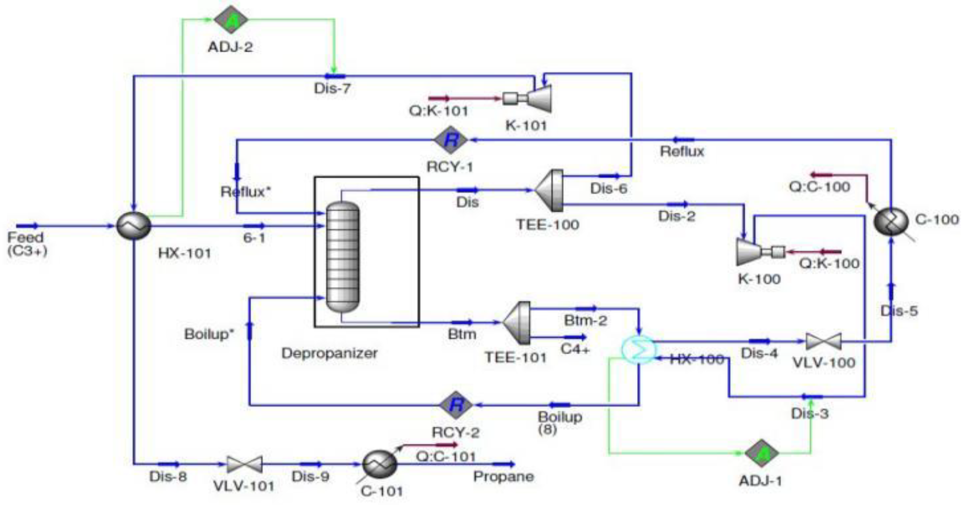
Figure 7 showcases the flow diagram for the IHC (Intermediate Heat Pump and Optimal Side Stream Return) design in the distillation system. This design incorporates both the intermediate heat pump and optimal side stream return principles, which contribute to the overall efficiency and performance of the system. In this configuration, the conventional condenser and reboiler can be observed. However, what sets the IHC design apart is the utilization of a heat pump system in the column through intermediate streams, rather than relying solely on heat exchange processes involving distillate, bottom product, or both, as seen in other configurations. The incorporation of the heat pump system through intermediate streams enhances the heat transfer and energy efficiency of the distillation system. It allows for precise control and optimization of heat distribution within the column, leading to improved separation and purification of the desired components. The IHC design emphasizes the use of intermediate streams to implement the heat pump system, providing a more efficient and effective approach to heat transfer within the distillation process. This design principle helps maximize energy usage and enhances the overall performance of the distillation system.
At stage 25, a vapor stream is extracted from the rectifying section of the column with a flow rate of 1000 kmol/h. This vapor stream is then compressed and condensed in the HX-100 heat exchanger before being returned to the column. This process helps maintain the desired operating conditions within the column and contributes to the separation and purification of the components. Simultaneously, a liquid stream with a flow rate of 600 kmol/h is taken from the stripping section at stage 48. This liquid stream is then evaporated in the HX-100 heat exchanger before being reintroduced back into the column at the same stage (stage 48). This step aids in optimizing the separation process within the column and ensures efficient operation. By extracting the vapor stream from the rectifying section and the liquid stream from the stripping section, and then subjecting them to compression, condensation, and evaporation in the HX-100 heat exchanger, the distillation system can maintain the desired temperature and pressure profiles within the column. This helps achieve the desired separation and product quality while optimizing the overall performance of the process.
The model utilized in this design is based on the heating and cooling potential of the streams or components involved. Prior to being charged to the column, the feed stream undergoes preheating through a heat exchange process with the compressed top product in HX-101. This heat exchange helps elevate the temperature of the feed stream, optimizing its efficiency within the distillation process. The distillate stream from the column is then separated into two streams: the top product and the reflux streams. These streams play essential roles in the distillation module, contributing to the separation and purification of the desired components. HX-101, which is responsible for compressing the top product stream, aids in warming the feed stream. By compressing the top product stream, heat is transferred to the feed stream, resulting in an increase in its temperature. This warm feed stream is then introduced into the column, facilitating the separation and purification processes. Through the preheating of the feed stream and the compression of the top product stream, the design optimizes energy usage and enhances the overall efficiency of the distillation process. This model prioritizes the effective utilization of heating and cooling poential to achieve optimal separation and product quality.
After being separated from the distillate stream, the reflux stream undergoes further processes. It is first inflated and chilled until it reaches its saturation temperature, optimizing its effectiveness in the distillation process. The compressed reflux stream is then used to reboil the bottom product, helping to enhance the separation and purification of the components in the column. This compression process increases the pressure and temperature of the reflux stream, enabling it to provide the necessary heat for the reboiling process. Meanwhile, the condensed stream from HX-100 undergoes expansion and cooling before being returned to the column. This expansion and cooling process help ensure that the stream is at the appropriate pressure and temperature to effectively contribute to the distillation process. To achieve a minimum temperature difference of 5°C in the heat exchangers, the outlet stream pressures of the compressors are carefully set. By adjusting the pressures, the desired temperature difference can be achieved, optimizing the performance of the heat exchangers and facilitating efficient heat transfer within the system. These processes, including chilling, compression, expansion, and cooling, are all part of the overall design to enhance the separation and purification processes in the distillation system. By carefully controlling the pressures and temperatures, the system can achieve the desired operating conditions and maximize the efficiency of the distillation process.
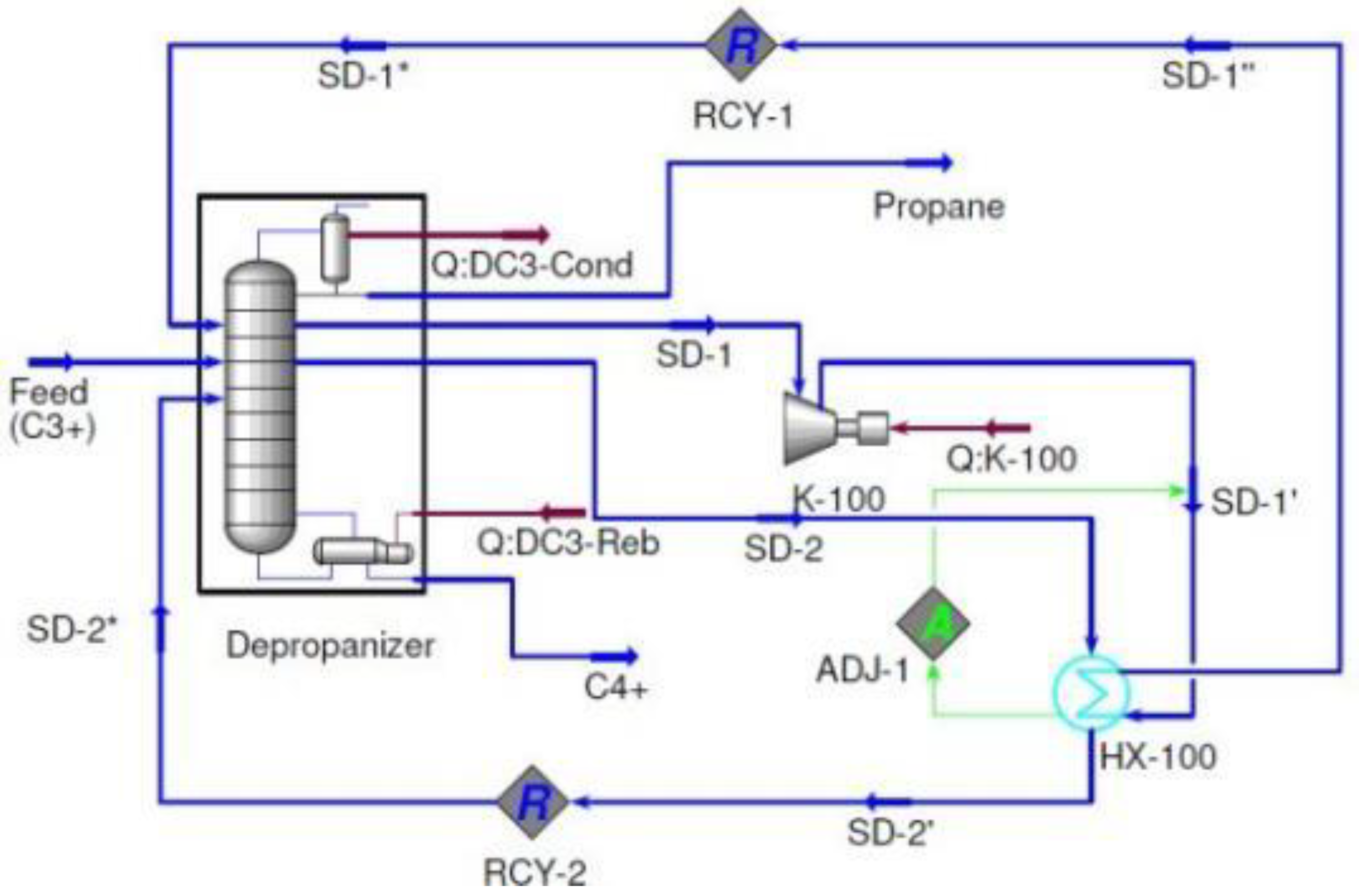
1.2. Modified self-heat recuperative (MSHR)
MSHR (Modified Single Heat Recovery) is an advanced version of SHR (Single Heat Recovery), as depicted in
Figure 9. Unlike SHR, MSHR requires only one compressor, K-100, in its arrangement. In this design, the overhead vapor from the column is compressed by the compressor, which is positioned at the top of the product stream. To condense the compressed vapor, HX-100 is employed. In HX-100, an adjust unit is incorporated to regulate the outlet pressure of the compressor. This adjustment is crucial to ensure that the minimum temperature approach of 5°C is met. By carefully controlling the compressor outlet pressure through the adjust unit, the MSHR design optimizes the heat transfer process in HX-100. This optimization helps achieve the desired temperature difference and enhances the efficiency of the overall system. MSHR offers a more streamlined and simplified configuration compared to SHR, as it eliminates the need for multiple compressors. This design modification enhances the overall performance and energy utilization of the distillation system, contributing to improved separation and product quality.
After the compressed vapor stream is condensed in HX-100, it is then passed through HX-101. HX-101 plays a crucial role in the process by providing heat to preheat the supply stream. This preheating step ensures that the supply stream reaches the desired temperature before entering the column, optimizing the efficiency of the distillation process. To match the pressure of the column, the pressure of the condensed stream is regulated by valve VLV-100. This valve helps maintain the desired pressure level, ensuring proper operation within the column. Additionally, the temperature of the condensed stream is controlled by valve C-100 to achieve its saturation temperature. This temperature control is essential for maintaining the desired conditions within the distillation system and facilitating effective separation and purification. Once the condensed stream has undergone pressure regulation and temperature control, it is then separated into two streams: the distillate and the reflux. This separation process ensures that the desired product streams are obtained while enabling the recycling of the necessary reflux stream to optimize the separation efficiency. By incorporating these steps, the distillation system can effectively control the pressure and temperature of the condensed stream, leading to improved operational performance and enhanced product quality.
2. Results and discussions
To determine the annual running cost for each configuration, we utilized the HYSYS simulation software to analyze the energy consumption of the condenser, re-boiler, cooler, and compressor. The running cost was calculated by combining the costs of cooling water, steam, and energy. By comparing the running cost of the base configuration, we were able to determine the percentage of energy savings achieved by the various alternatives
In
Table 3 , you can find the utility costs that encompass cooling water, steam, and electricity. To evaluate the energy duty and operating costs for both the base configuration (BC) and alternate configurations, you can refer to
Table 4 and
Table 5. For the BC layout, the total re-boiler duty required is 4.88 MW, while the condenser duty needed amounts to 5.87 MW. These figures will serve as a basis for comparing the various configurations in this investigation.
According to
Table 4, it appears that all the retrofit choices, except for the TVR (Thermo Vapor Re-compression), have a lower cooling duty than the base configuration (BC). The TVR, on the other hand, has a cooling duty that is 10.56 percent higher than the BC. This increase in cooling duty is due to the fact that the compressed pressure required in the TVR is achieved by mixing the input steam with the distillate. As a result, the volume of vapor that needs to be condensed and further cooled after achieving its goal of reboiling the bottom product stream from the column is significantly higher than in any of the proposed configurations.
As a result, the stream requires more cooling water for condensation and cooling. Out of the available options, MVR stands out with the lowest cooling energy requirement, only 3.80 MW, resulting in a remarkable energy saving of 35.26%. Following closely is VC, requiring 3.95 MW, while MSHR requires 4.22 MW. BF and SHE require 4.37 MW and 4.62W respectively. SHR and IHC require 5.07 MW and 5.34 MW respectively.
Table 4 displays the heating duty of different distillation systems. The heating duty mentioned here specifically refers to the use of steam as the heat source. It's important to note that while compressors do provide heat energy through compression, the electrical power they consume is not factored into the estimation of the heating duty. This is because their function is distinct and their energy sources differ.
Table 4 reveals that not all configurations require external heat from steam to heat up the outflow stream of the bottom column. Among the configurations mentioned, BC, TVR, SHE, and IHC are the only ones that require steam energy. However, even though these sophisticated distillation arrangements require steam energy, their energy requirements are still lower compared to the BC configuration.
Among the designs compared to BC, TVR has the highest steam energy requirement. In TVR, the use of steam for compression purposes to heat or boil the stream results in the least amount of energy saving. This is different from other arrangements where compressors are used to increase the energy content of the streams by compressing them. However, the ejector in TVR can help reduce the energy requirement by increasing the energy content of the steam before it is utilized in the heat exchanger.
Following TVR, the designs of IHC and SHE have the next highest steam energy requirements. In contrast, other alternatives like VC, MVR, BF, SHR, and MSHR have eliminated the need for reboiling, resulting in a 100% reduction in heating duty compared to the BC configuration. This significant reduction in heating duty is made possible by the removal of the reboiler from these alternative designs.
Table 5 presents the results of the annual running costs and cost savings. It is evident that all the retrofit choices have lower annual running costs compared to the BC configuration, which amounts to
$1,992,300 per year. Among these options, MVR stands out with the lowest annual operating cost of
$635,280, resulting in a significant savings of 68.11 percent when compared to the BC. The configuration of MVR without a reboiler contributes to its low cooling duty of 3.80 MW and compressor duty of 2.82 MW.
Indeed, the annual running cost of VC is slightly higher than that of MVR, amounting to $664,380. However, VC still provides significant savings of 66.65% compared to the traditional column configuration. It's impressive to see how these retrofit choices offer cost-effective alternatives with substantial cost savings.
The MSHR configuration has the third highest operating cost, amounting to
$716,760 per year, but still provides a significant savings of 64.02% compared to the BC. Following MSHR, we have the BF, SHR, SHE, IHC, and TVR configurations, with energy cost savings of 62.88%, 55.85%, 54.23%, 39.54%, and 12.41% respectively. As we can observe from
Table 4, configurations that do not rely on steam as the primary heating source tend to have lower annual operating costs. This emphasizes the importance of considering alternative heating methods to achieve cost savings in distillation systems
The results presented indicate that configurations like IHC and SHE, which include reboilers in their designs, have higher operating costs. This suggests that minimizing or eliminating the reliance on steam as the heat source would be advantageous in distillation system design. While TVR does not have a reboiler, its higher annual operating cost compared to other alternatives is primarily due to the significant amount of steam used for compressing the stream through the ejector. It highlights the importance of carefully considering the trade-offs between energy consumption and operating costs when designing distillation systems.
In the research study "Elevating Natural Gas Liquid (NGL) Extraction and Fractionation Train Performance: A Synergistic Approach of Simulation Analysis, Advanced Modification, and Vertical Advancement," several figures were utilized to illustrate different aspects of the research findings. Here's a breakdown of the application and utilization of the figures mentioned:
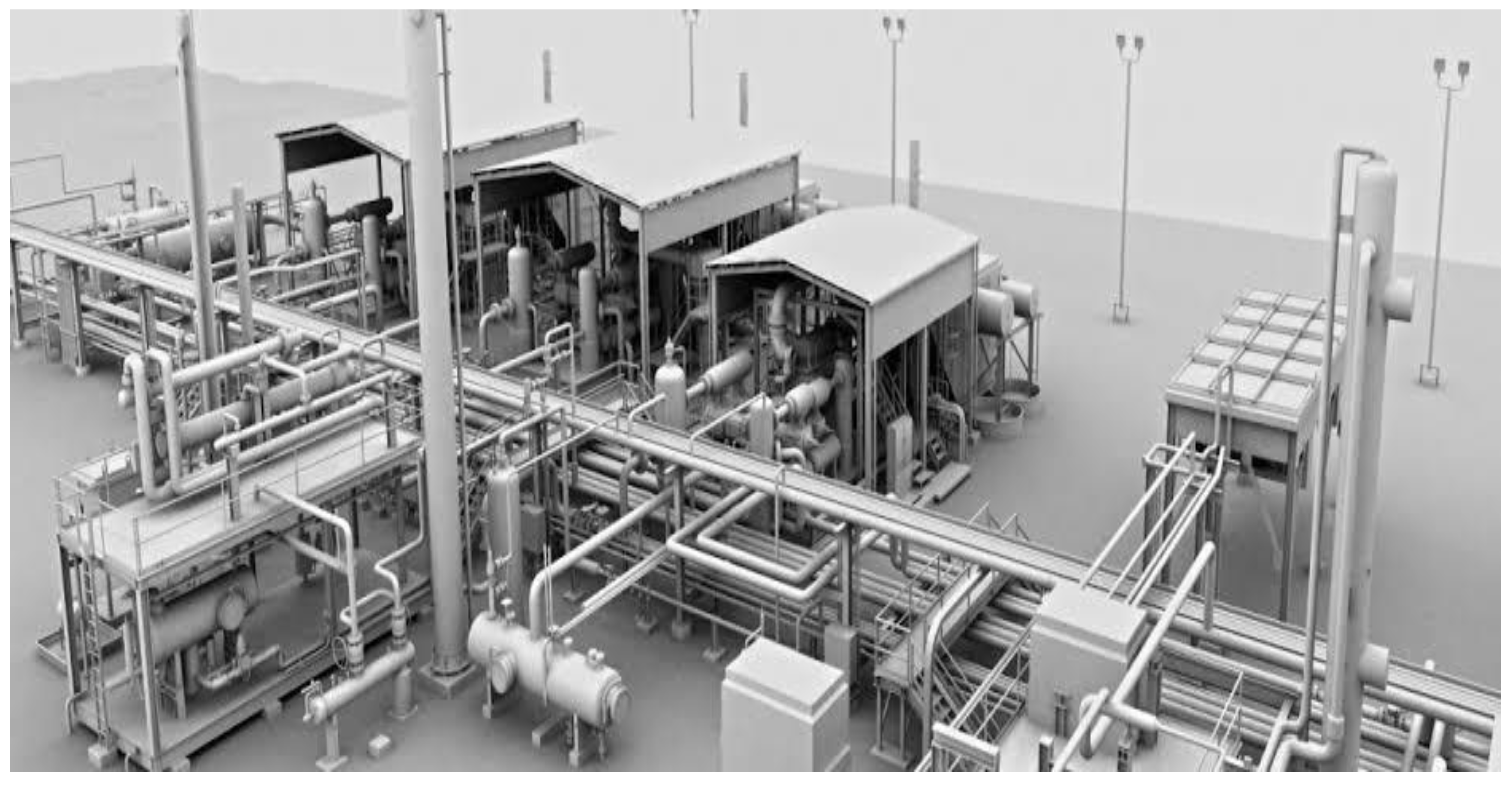
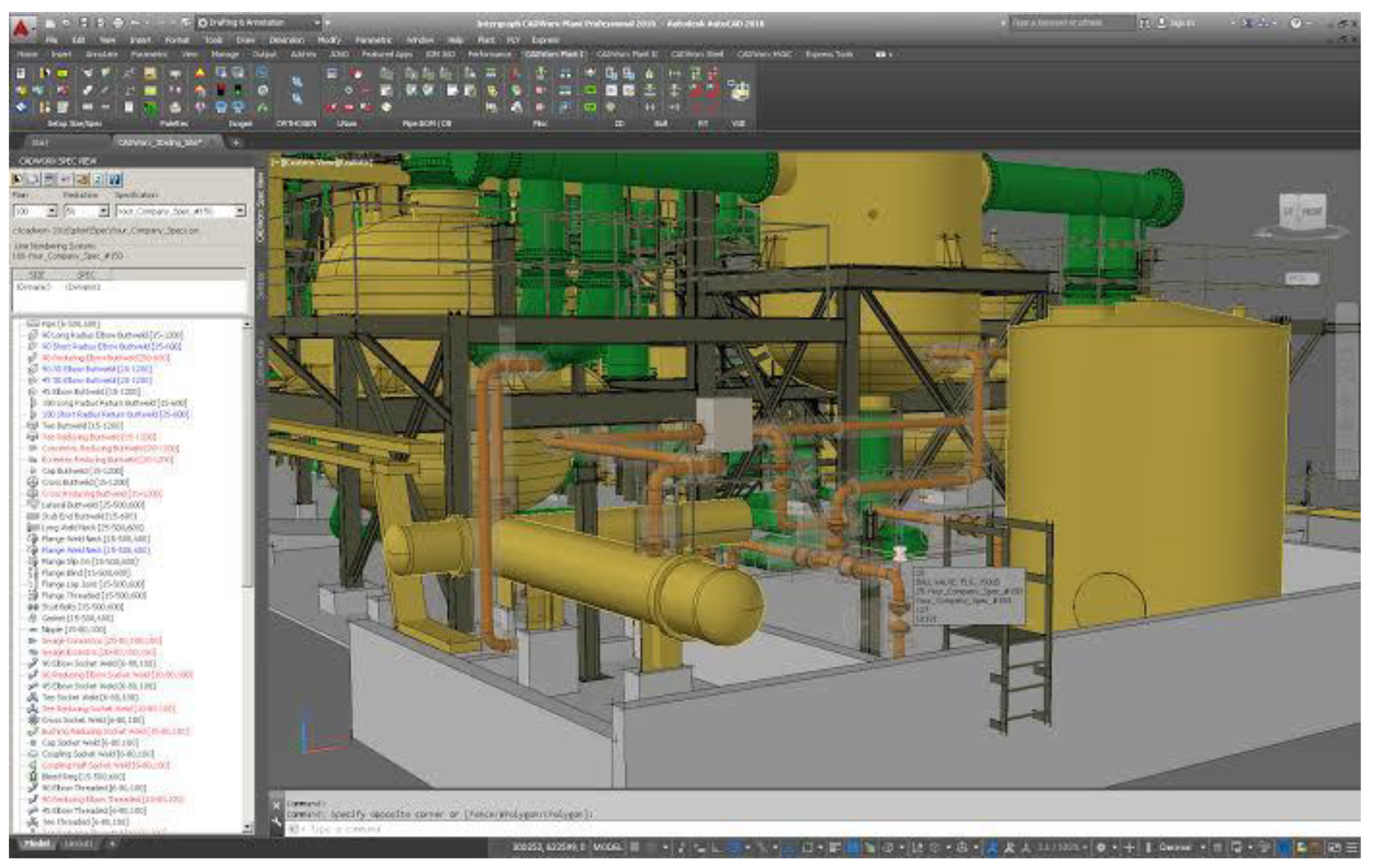
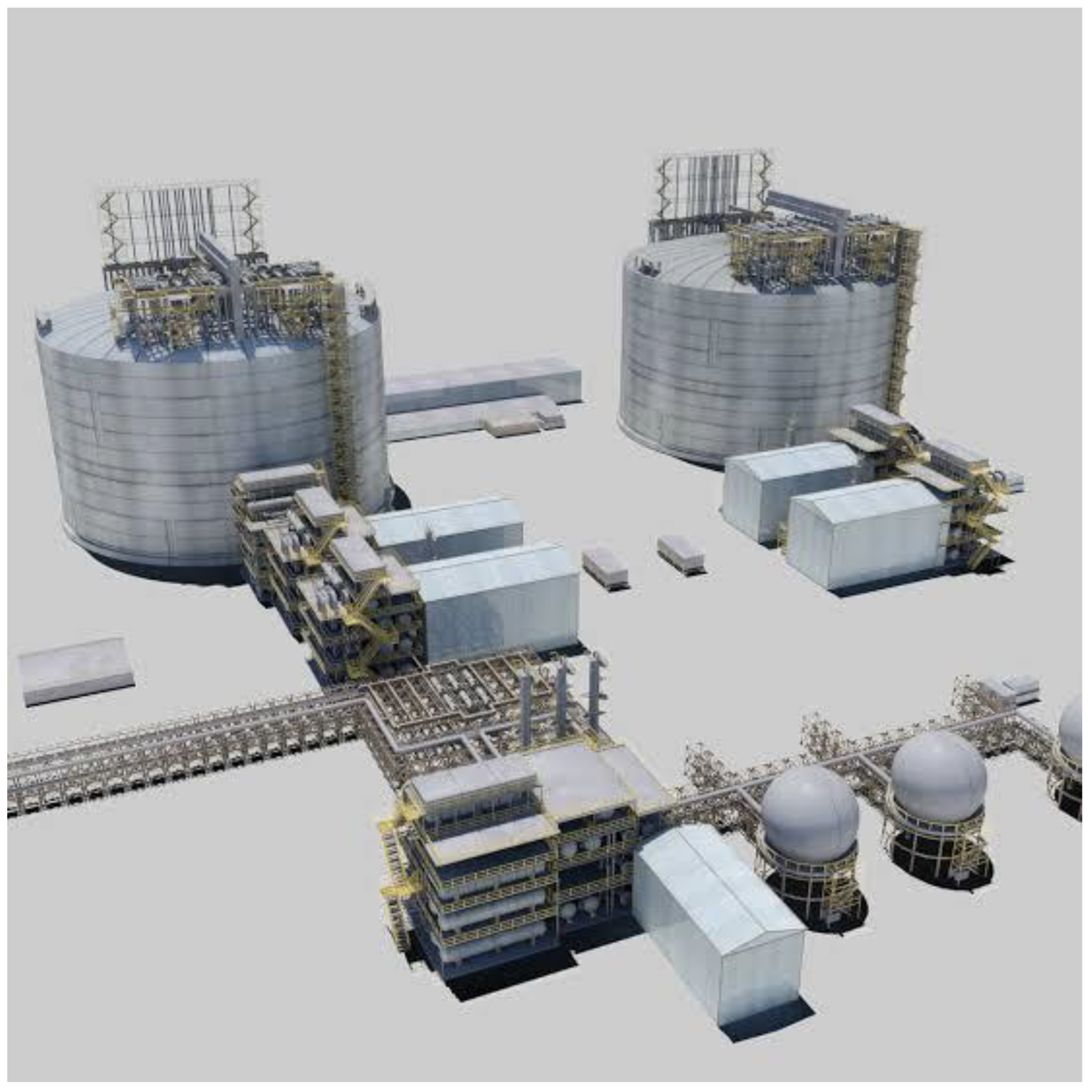
Figure 10: 3D Modelling of a Gas Processing Facilities This figure presents a three-dimensional model showcasing the gas processing facilities. It helps visualize the layout and design of the facilities, including various equipment and components involved in NGL extraction and fractionation.
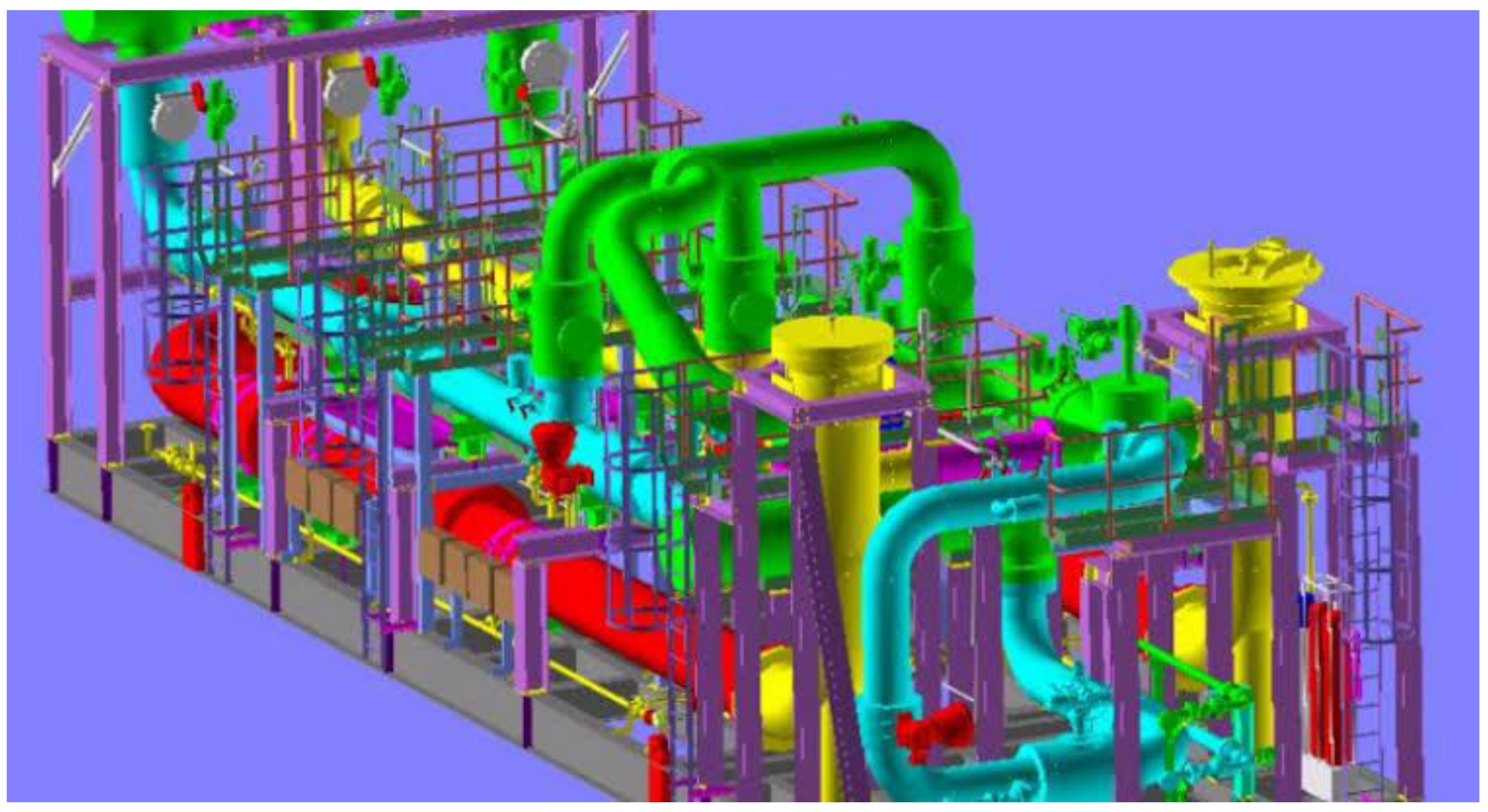
Figure 11: Gas Metering Skids This figure demonstrates the gas metering skids used in the research. It provides an overview of the equipment and instrumentation involved in measuring the flow rate and volume of gas within the processing facilities.
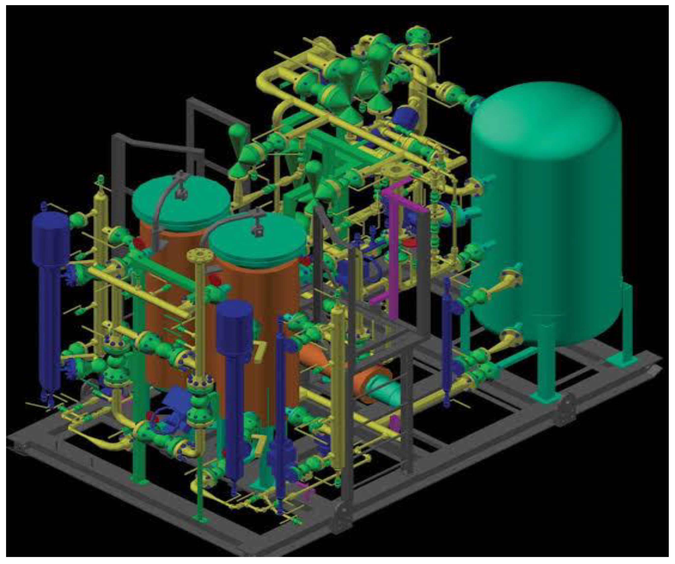
Figure 12: Fuel Gas Skids This figure highlights the fuel gas skids utilized in the research. It displays the equipment and systems responsible for supplying fuel gas to different processes within the gas processing facilities.
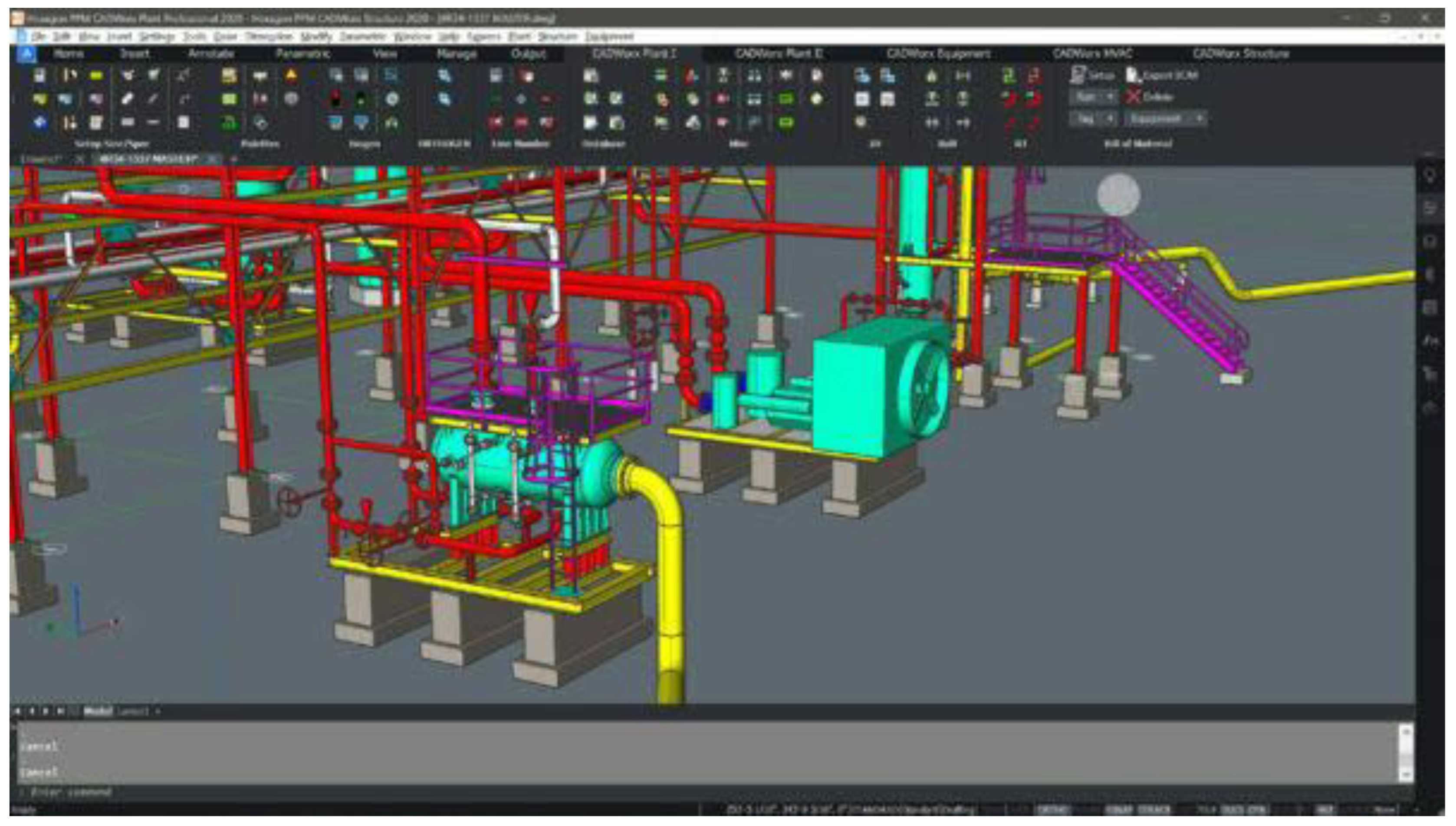
Figure 13: Full Plant Gas Design Engineering This figure showcases the full plant gas design engineering of the facilities. It encompasses the overall planning and engineering involved in the design and construction of the gas processing plant, taking into account various factors such as capacity, safety, and efficiency. These figures contribute to a comprehensive understanding of the research topic by visually representing different aspects of the gas processing facilities, metering systems, fuel gas supply, and overall plant design and engineering..
Figure 14: Natural Gas Engineering Design Plants This figure presents the engineering design of natural gas plants. It showcases the various components and processes involved in the extraction, processing, and treatment of natural gas.
Figure 15: Engineering Plant Design Layout of Natural Gas This figure illustrates the layout and design of a natural gas plant. It provides a visual representation of how different units, equipment, and infrastructure are arranged to optimize the efficiency and functionality of the plant.
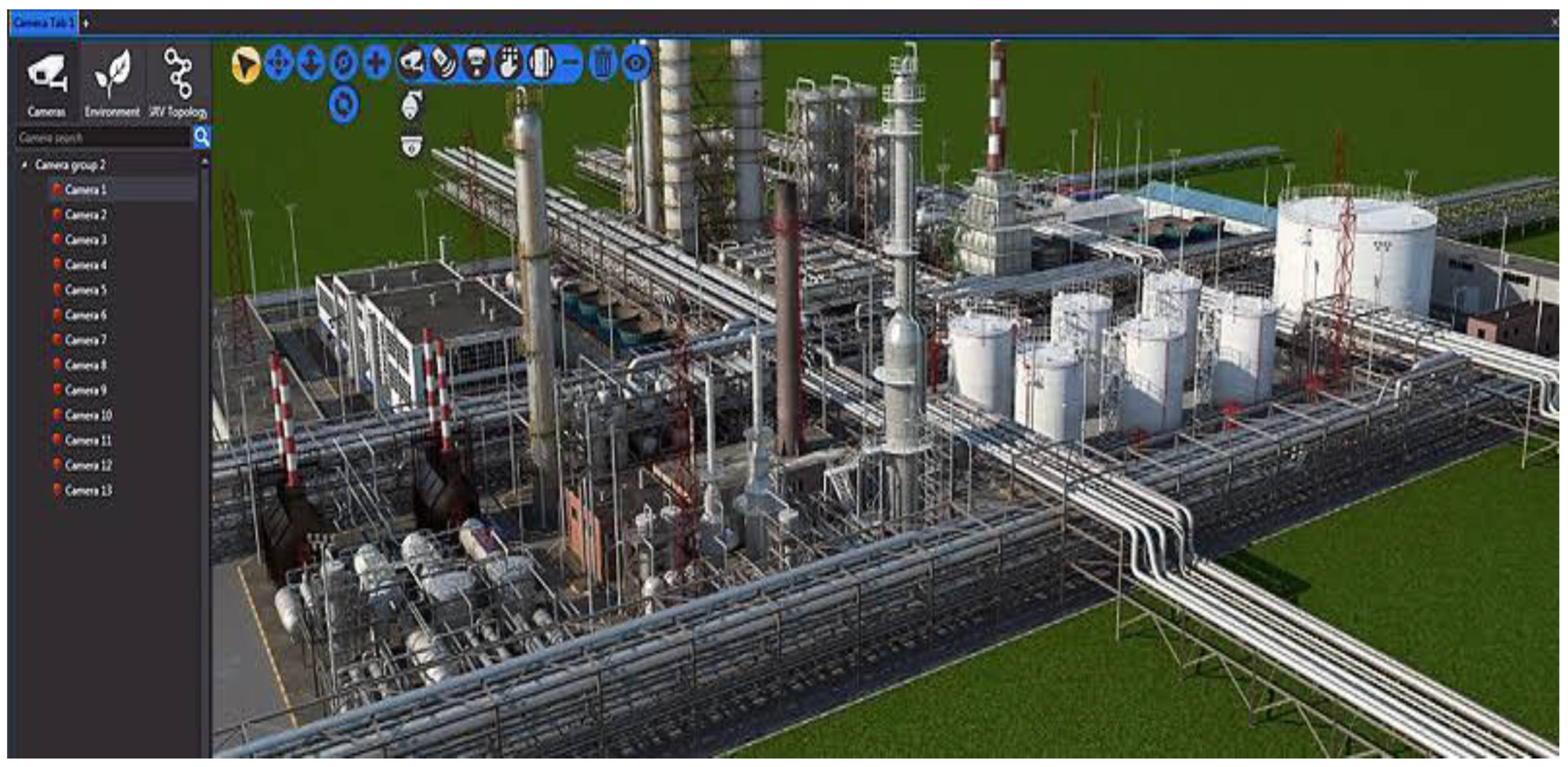
Figure 16: Visualization of Natural Gas Refineries Platform This figure provides a visual representation of a platform where natural gas refineries are located. It helps to understand the spatial organization and structure of the refineries, including the different processing units and equipment involved.
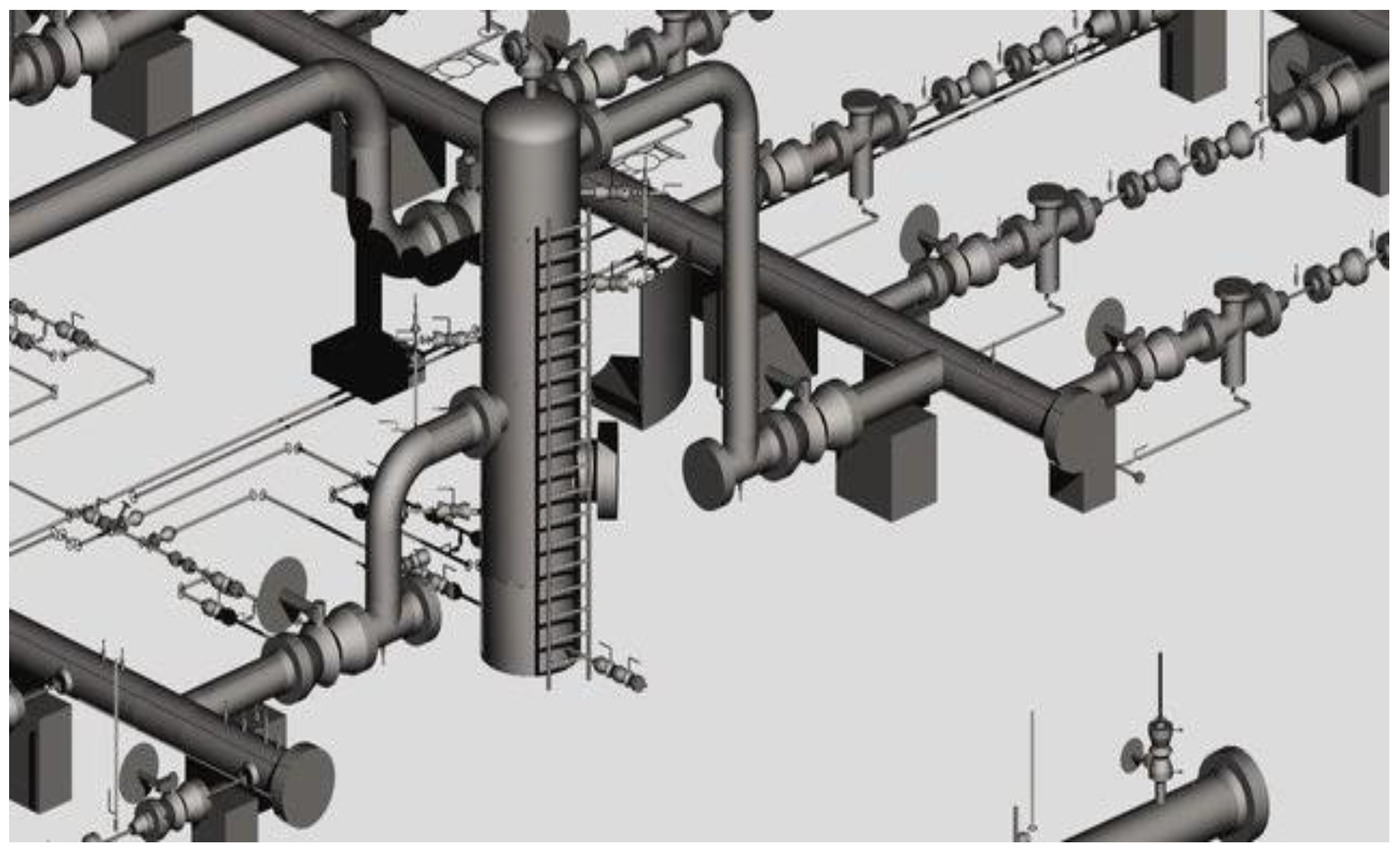
Figure 17: Oil and Gas Pipeline Engineering Model This figure showcases an engineering model of an oil and gas pipeline system. It demonstrates the design and layout of the pipeline network used for transporting natural gas and oil from extraction sites to processing facilities or distribution points.
Figure 10.
3D Modelling of a Gas processing Facilities.
Figure 10.
3D Modelling of a Gas processing Facilities.
Figure 11.
Gas Metering Skids Design.
Figure 11.
Gas Metering Skids Design.
Figure 12.
:fuel Gas Skid.
Figure 12.
:fuel Gas Skid.
Figure 13.
full plant Gas Engineering.
Figure 13.
full plant Gas Engineering.
Figure 14.
Engineering plants Design Layout of Natural Gas.
Figure 14.
Engineering plants Design Layout of Natural Gas.
Figure 15.
Visualization of Natural Gas Refineries Platform.
Figure 15.
Visualization of Natural Gas Refineries Platform.
Figure 16.
Oil & Gas Pipelines Engineering Model.
Figure 16.
Oil & Gas Pipelines Engineering Model.
Figure 17.
Industrial Natural Gas Liquefaction Plant.
Figure 17.
Industrial Natural Gas Liquefaction Plant.
Figure 18: Industrial Natural Gas Liquefaction Plant This figure depicts an industrial plant designed for the liquefaction of natural gas. It shows the various equipment and processes involved in transforming natural gas into a liquid state for storage and transportation. These additional figures provide valuable visual insights into the engineering aspects of natural gas plants, refineries, pipelines, and liquefaction facilities. They contribute to a better understanding of the design, layout, and functionality of these systems within the context of the research..
Table 3 displays the utility cost data, specifically for cooling water. It includes information about the prices per unit for steam and electricity. - Steam is priced at
$300 per kilowatt-hour per year. - Electricity is priced at
$104 per kilowatt-hour per year. These prices represent the cost associated with utilizing these utilities, specifically for cooling water purposes. It's important to consider these costs when evaluating the overall operational expenses and efficiency of the system.
In the context of distillation processes, energy duty evaluation is essential for understanding the energy requirements and potential energy savings associated with different arrangements.
Table 4 provides a comprehensive summary of this evaluation for various distillation arrangements, including BC, VC, MVR, TVR, BF, SHE, IHC, SHR, and MSHR. The first row of the table represents the Reboiler/Ejector Duty in megawatts (MW) for each arrangement. This duty refers to the heat input required to generate the necessary vapor for the separation process. In the BC arrangement, the Reboiler/Ejector Duty is 4.87 MW. However, for the BF arrangement, it is lower at 3.88 MW, indicating potential energy savings compared to the base case. The IHC arrangement demonstrates further energy efficiency improvements with a Reboiler/Ejector Duty of only 0.60 MW. Lastly, the SHR arrangement shows a moderate reduction in the Reboiler/Ejector Duty, with a value of 1.38 MW. The second row of the table presents the Compressor Duty in MW for each arrangement. Compressors are essential components for maintaining the required pressure levels in distillation processes. In the BC arrangement, the Compressor Duty is 2.96 MW. Comparatively, VC, MVR, TVR, BF, SHE, and MSHR arrangements demonstrate varying levels of Compressor Duty, ranging from 2.82 MW to 4.07 MW. Notably, the MVR arrangement shows the highest Compressor Duty at 3.34 MW, indicating a potential trade-off between energy consumption and the advantages of mechanical vapor recompression. The third row of the table represents the Cooling Duty Saving in percentage for each arrangement. Cooling duty refers to the heat removal required to condense the vapor and recover valuable energy. The values provided in the table indicate the percentage of cooling duty saved compared to the base case. The VC arrangement demonstrates significant savings with a value of 32.72%. Similarly, the MVR and SHE arrangements show substantial cooling duty savings, with values of 35.26% and 25.55% respectively. On the other hand, the TVR arrangement indicates a negative value of -10.56%, suggesting an increase in cooling duty requirements compared to the base case. The IHC, SHR, and MSHR arrangements demonstrate more moderate cooling duty savings, ranging from 9.04% to 28.12%. Overall,
Table 4 provides a comprehensive overview of the energy duty evaluation for various distillation arrangements. It highlights the potential energy savings and efficiency improvements associated with different configurations, aiding in the decision-making process for optimizing distillation processes to achieve enhanced energy efficiency and sustainability
Table 5 presents a summary of the operating cost evaluation for various distillation arrangements: The first column represents the different distillation arrangements: BC (Base Case), VC (Vapor Compression), MVR (Mechanical Vapor Recompression), TVR (Thermal Vapor Recompression), BF (Booster Fan), SHE (Subcooled Heat Exchange), IHC (Integrated Heat Pump), SHR (Subcooled Heat Recovery), and MSHR (Multiple-stage Heat Recovery). The following rows represent the operating costs associated with each arrangement: 1. Cooling Water Cost (
$/year): This row indicates the annual cost of cooling water required for the distillation process. The values provided are
$528,300 for BC,
$355,500 for VC,
$342,000 for MVR,
$584,100 for TVR,
$393,300 for BF,
$415,800 for SHE,
$480,600 for IHC,
$456,300 for SHR, and
$379,800 for MSHR. 2. Steam Cost (
$/year): This row displays the annual cost of steam utilized in the distillation process. The values provided are
$1,464,000 for BC,
$1,161,000 for TVR,
$180,000 for IHC, and
$414,000 for SHR. 3. Electricity Cost (
$/year): This row represents the annual cost of electricity consumed by the various distillation arrangements. The values provided are
$308,880 for VC,
$293,280 for MVR,
$346,320 for BF,
$316,160 for SHE, and
$309,920 for MSHR. The operating cost evaluation in
Table 5 helps assess the economic feasibility and cost-effectiveness of different distillation arrangements. It provides insights into the varying expenses associated with cooling water, steam, and electricity consumption, enabling decision-makers to identify arrangements that offer potential cost savings and improved operational efficiency. Please note that the units for all values in the table are in dollars per year (
$/yr).
