The depropanizer unit and its advanced distillation options were modeled and simulated using the Aspen HYSYS V7.3 simulator. To accurately predict the vapor-liquid equilibrium for a wide range of operating conditions, particularly for light hydrocarbon mixtures, the Peng Robinson property package was selected as the equation of state. In modern distillation systems, compressors or steam ejectors are employed to enhance the energy content of the streams. For all the simulated compressors, an adiabatic efficiency of 75 percent was anticipated. During the heat exchange process, all heat exchangers were designed to stand with a minimum temperature of 5 degree Celsius and a pressure drop of 0.34 bar(5 psi).
Conventional Distillation System
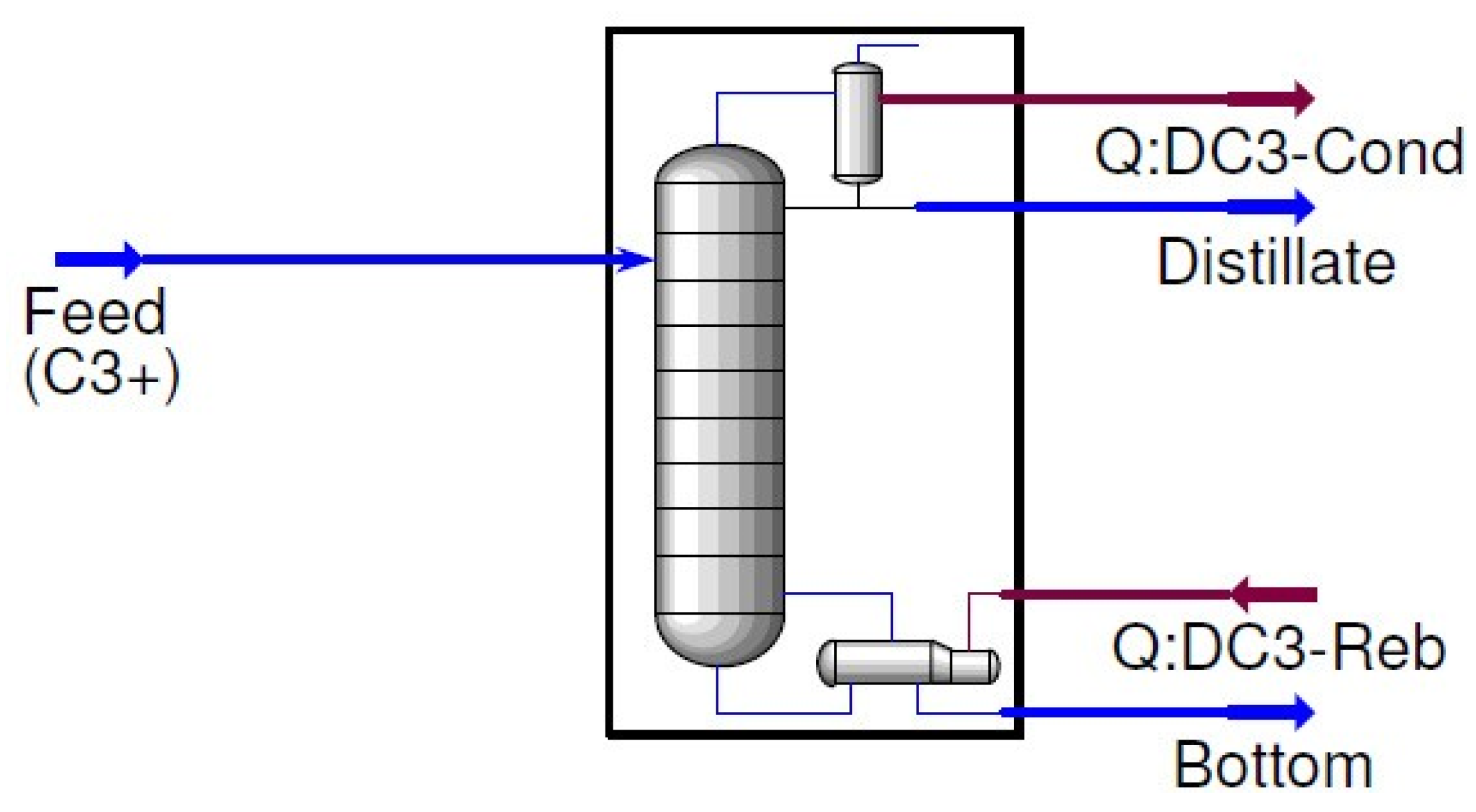
The case study focuses on a depropanizer at a natural gas processing plant in Nigeria. The study used Aspen HYSYS to create a flow diagram for the traditional distillation setup, which was used as a reference point for different strategies examined in the study. In this Traditional layout, the bottom product from a de-ethanizer in the plant is used as the feedstock for the depropanizer unit. In the depropanizer column discussed in the study, the propane is separated as the distillate, while the remaining light hydrocarbons make up the bottom product.
Table 1 provides information on the composition, temperature, and pressure of the depropanizer feed, while
Table 2 presents the operating conditions and product parameters of the column. According to the simulation, the molar flow rates for the top and bottom product streams were 531.6 and 358.8 kmol/h, respectively. Throughout the analysis, the study maintained consistent feed conditions column settings, and product standard
Figure 1.
HYSYS flow diagram for the conventional distillation column.
Figure 1.
HYSYS flow diagram for the conventional distillation column.
Table 1 presents the feed conditions of the depropanizer column. It outlines the mole fraction of each component in the feed, as well as the total molar flow, temperature, and pressure. - The feed composition consists of various hydrocarbon components, including ethane (C2), propane (C3), i-butane (iC4), n-butane (nC4), i-pentane (iC5), n-pentane (nC5), n-hexane (nC6), n-Heptane (nC7), n-octane (nC8), and n-Nonane (nC9). - Each component is represented by its respective mole fraction, indicating the proportion of that component within the feed mixture. For example, propane (C3) has a mole fraction of 0.5959, indicating that it constitutes approximately 59.59% of the feed mixture. - The total molar flow of the feed is calculated to be 890.3 kmol/h, representing the overall quantity of material entering the depropanizer column. - The temperature of the feed is measured at 71.11°C, indicating the initial temperature at which the feed enters the column. - The pressure of the feed is recorded as 16.00 bar, representing the initial pressure at which the feed is introduced into the column. These feed conditions provide important information about the composition, quantity, temperature, and pressure of the incoming feed, which are crucial factors for the depropanizer column’s operation and performance.
Table 2 showcases the column and product specifications, as well as the energy performance of the existing depropanizer. - The column consists of a total of 50 trays, divided into different categories. - The feed is introduced at tray locations labeled as Feed 1 and Feed 2, specifically at tray number 25. - The depropanizer demonstrates high efficiency in recovering propane (C3) at the top stream, with a mole fraction of 0.998. This indicates that it successfully captures 99.8% of the propane present in the feed. - Similarly, the depropanizer exhibits efficient recovery of butane (C4) at the bottom stream, with a mole fraction of 0.991. This signifies that it captures 99.1% of the butane present in the feed. - The top product stream from the depropanizer carries a total molar flow of 531.7 kmol/h, representing the amount of material leaving the column as the desired product. - On the other hand, the bottom product stream has a total molar flow of 358.9 kmol/h, indicating the quantity of material exiting the column as the byproduct. - The pressure of the top product stream is measured at 14.90 bar, while the pressure of the bottom product stream is slightly higher at 16.21 bar. These specifications provide valuable insights into the operational performance and output of the existing depropanizer column.
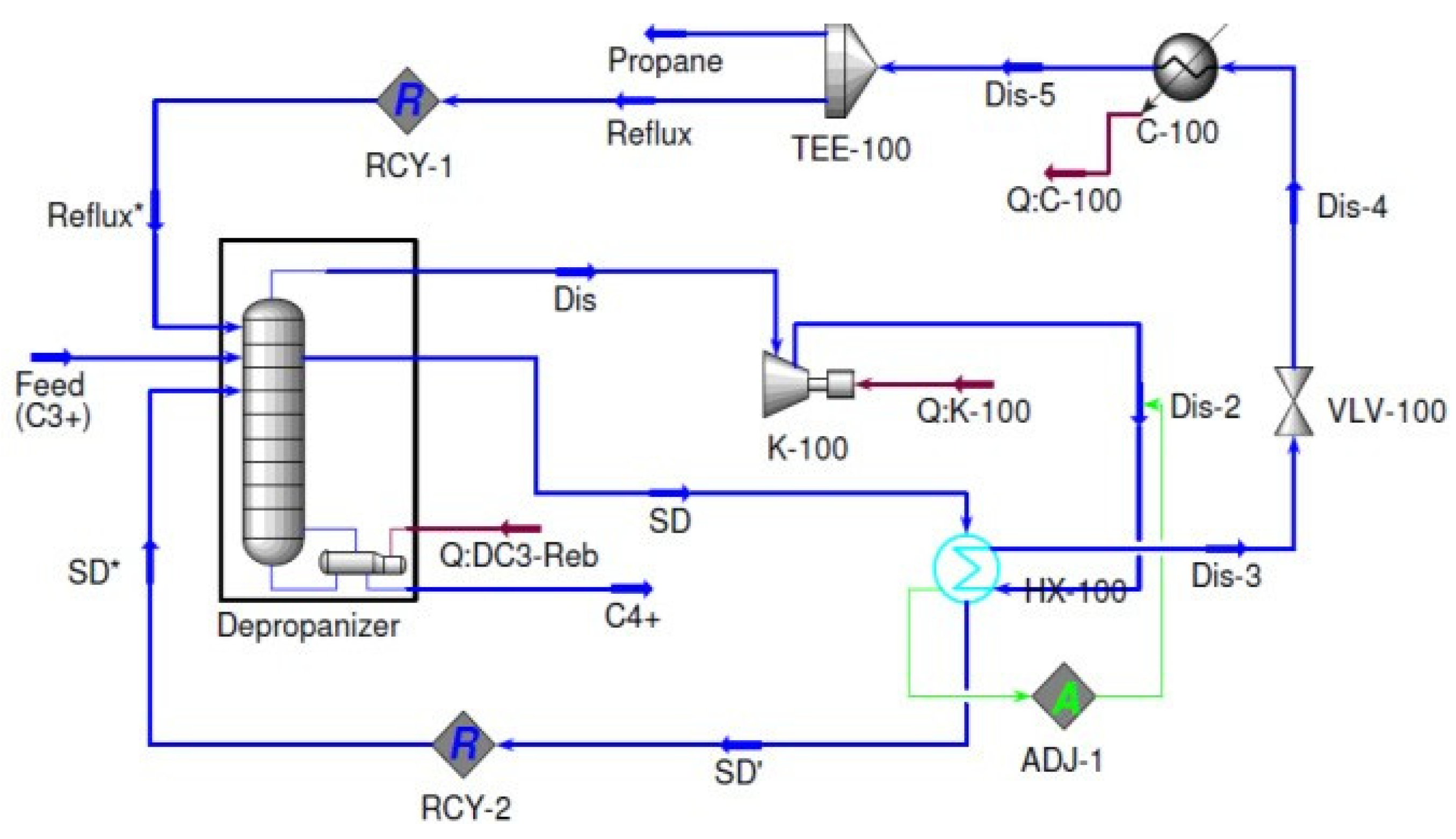
In the Vapor Compression (VC) system, a closed cycle heat pump configuration is employed, utilizing a refrigerant that circulates between the condenser and the reboiler. This system is designed to optimize energy efficiency.
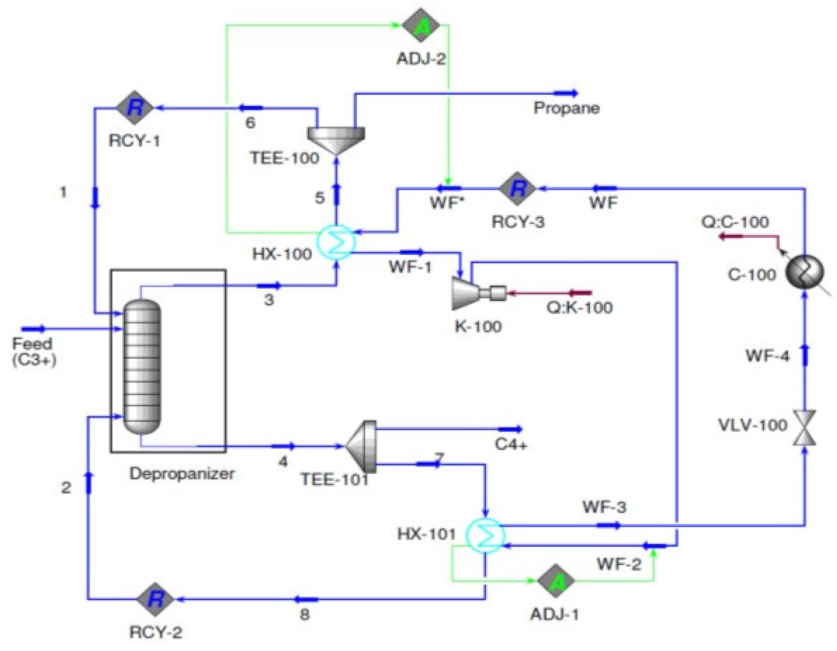
Figure 2 depicts the HYSYS flow diagram of the Vapor Compression system being investigated. In this specific study, propylene (R-1270) was chosen as the refrigerant [
9]. Within the system, the refrigerant initiates evaporation in the condenser HX-100, where it efficiently exchanges heat with the overhead product in the refrigeration cycle. Following vaporization, the refrigerant undergoes compression through the action of compressor K-100.
Figure 2.
Vapor Compression (VC) System.
Figure 2.
Vapor Compression (VC) System.
Following compression, the refrigerant is directed to reboiler HX-101 where it undergoes condensation. Subsequently, an expansion process takes place, resulting in a decrease in saturation temperature. Before being reintroduced into condenser HX-100, the partially condensed refrigerant stream requires additional cooling. To determine the necessary molar flow rate of the refrigerant, an adjustment unit is utilized at condenser HX-100.Furthermore, to optimize the performance and efficiency of the VC system, an additional adjustment unit is employed at the outlet of the compressor to regulate the pressure of the refrigerant stream. These adjustments play a crucial role in achieving optimal system operation.
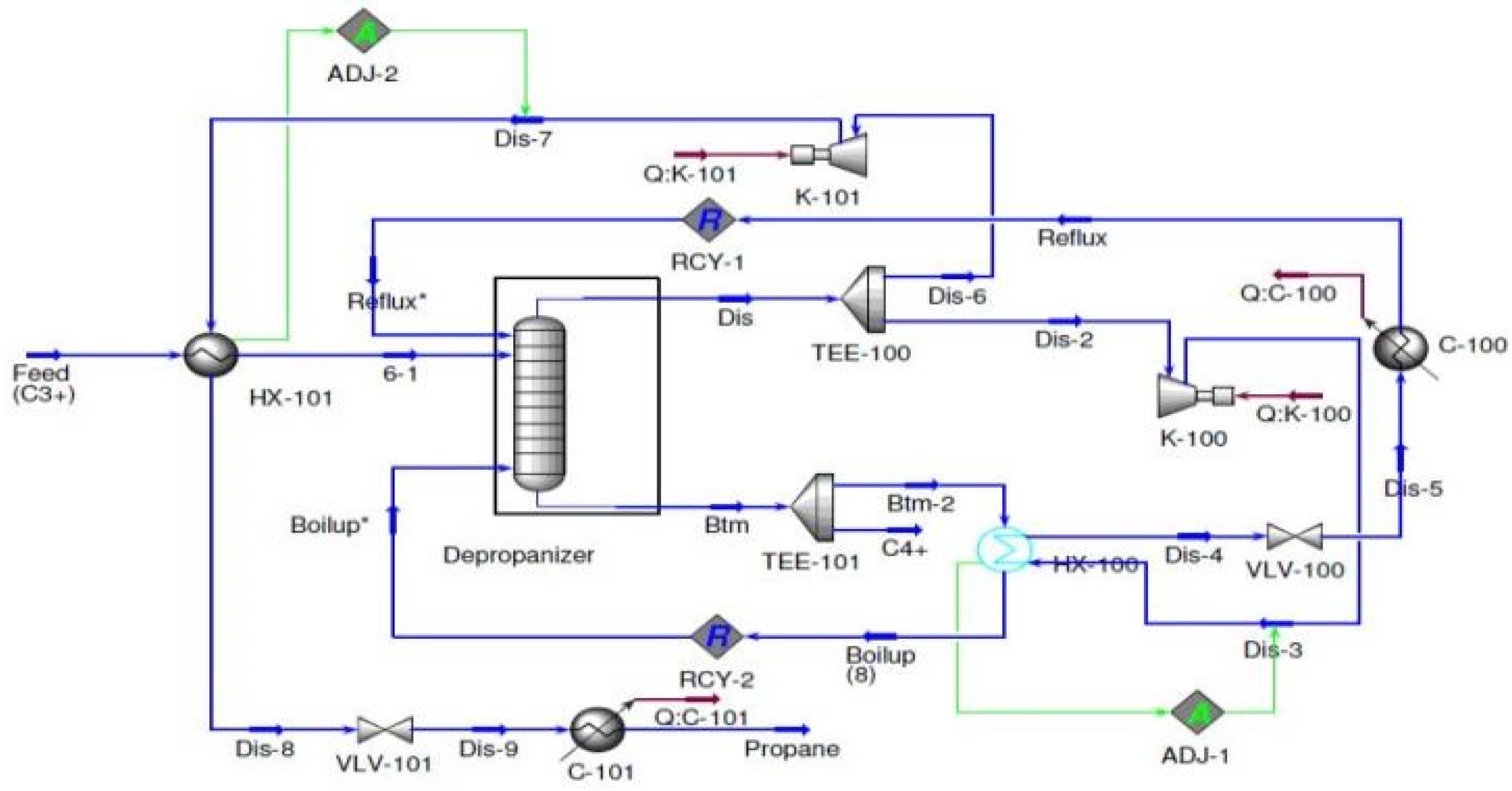
Figure 3 showcases the HYSYS flow diagram for the Mechanical Vapor Recompression (MVR) system, which is widely employed as an open cycle heat pump in distillation systems. In this system, one of the key steps involves the compression of the distillate using compressor K-100, resulting in a notable increase in its temperature. This process is instrumental in facilitating the overall functionality and efficiency of the MVR system within distillation operations.:
Figure 3.
Mechanical vapor re-compression (MVR).
Figure 3.
Mechanical vapor re-compression (MVR).
In order to attain a minimum temperature approach of 5°C in heat exchanger HX-100, an adjustment unit is employed to calculate the pressure at the outlet of the compressor. This adjustment is crucial for optimizing the system’s performance and guaranteeing the desired temperature approach is achieved in the heat exchanger. By carefully controlling the pressure, the system can efficiently maintain the desired temperature conditions, leading to improved overall operation.
Upon compression, the elevated temperature stream is guided through heat exchanger HX-100, where it engages in heat exchange with the bottom product stream. Within HX-100, the compressed stream is condensed, releasing the required heat to initiate the boiling process of the bottom product. Subsequently, the condensed stream undergoes expansion to reach the pressure at the column top, and it is further cooled to its saturation temperature before being recycled back to the column top or separated as the top product. This sequence of steps ensures efficient operation and optimal temperature conditions within the system. Following its vaporization, the stream is subsequently recirculated back to the bottom of the column at a later stage. This recirculation process plays a crucial role in optimizing energy utilization and further enhancing the overall efficiency of the distillation system. By reintroducing the vaporized stream, the system can achieve improved separation and maximize the energy efficiency of the distillation process.
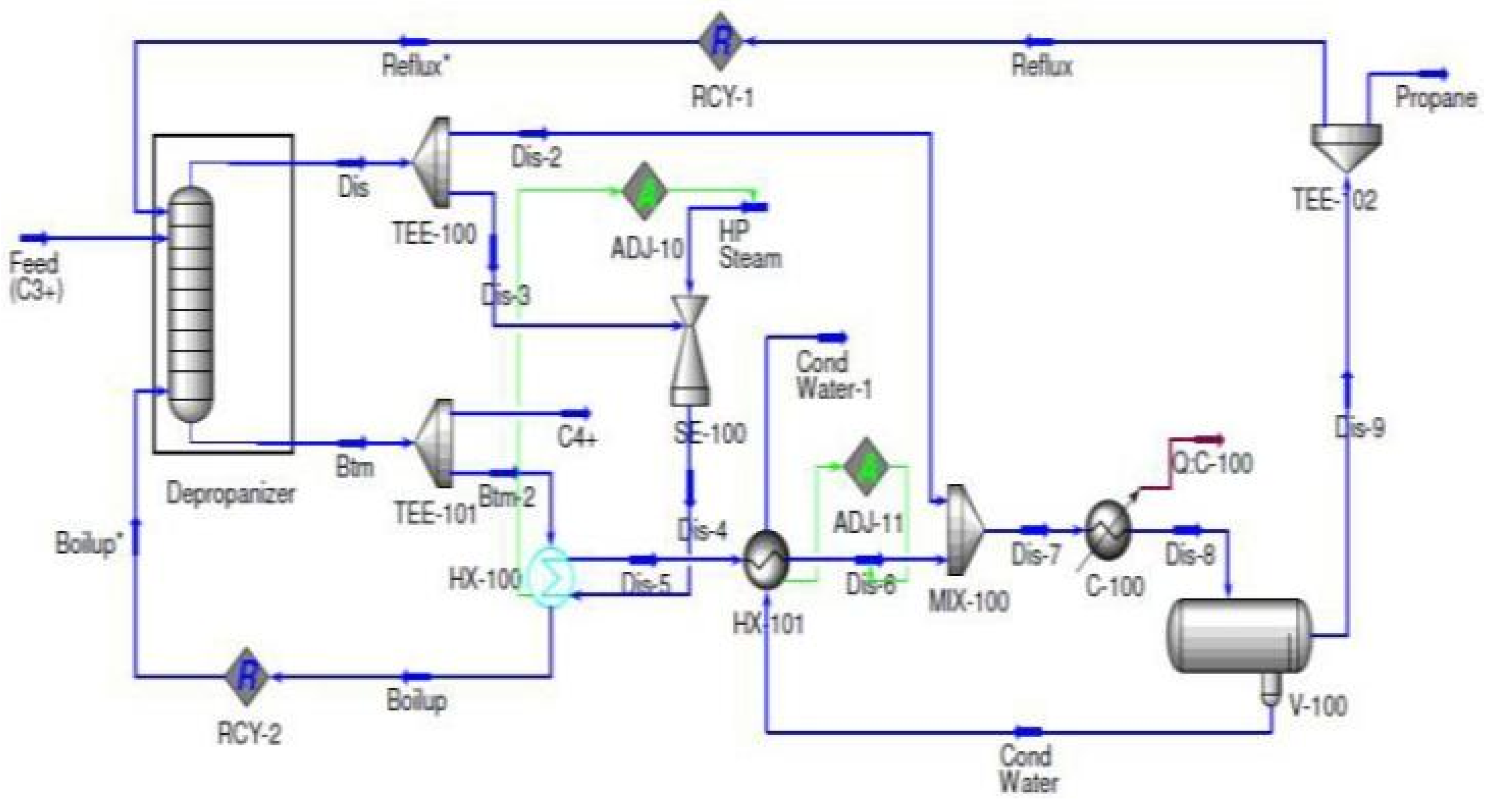
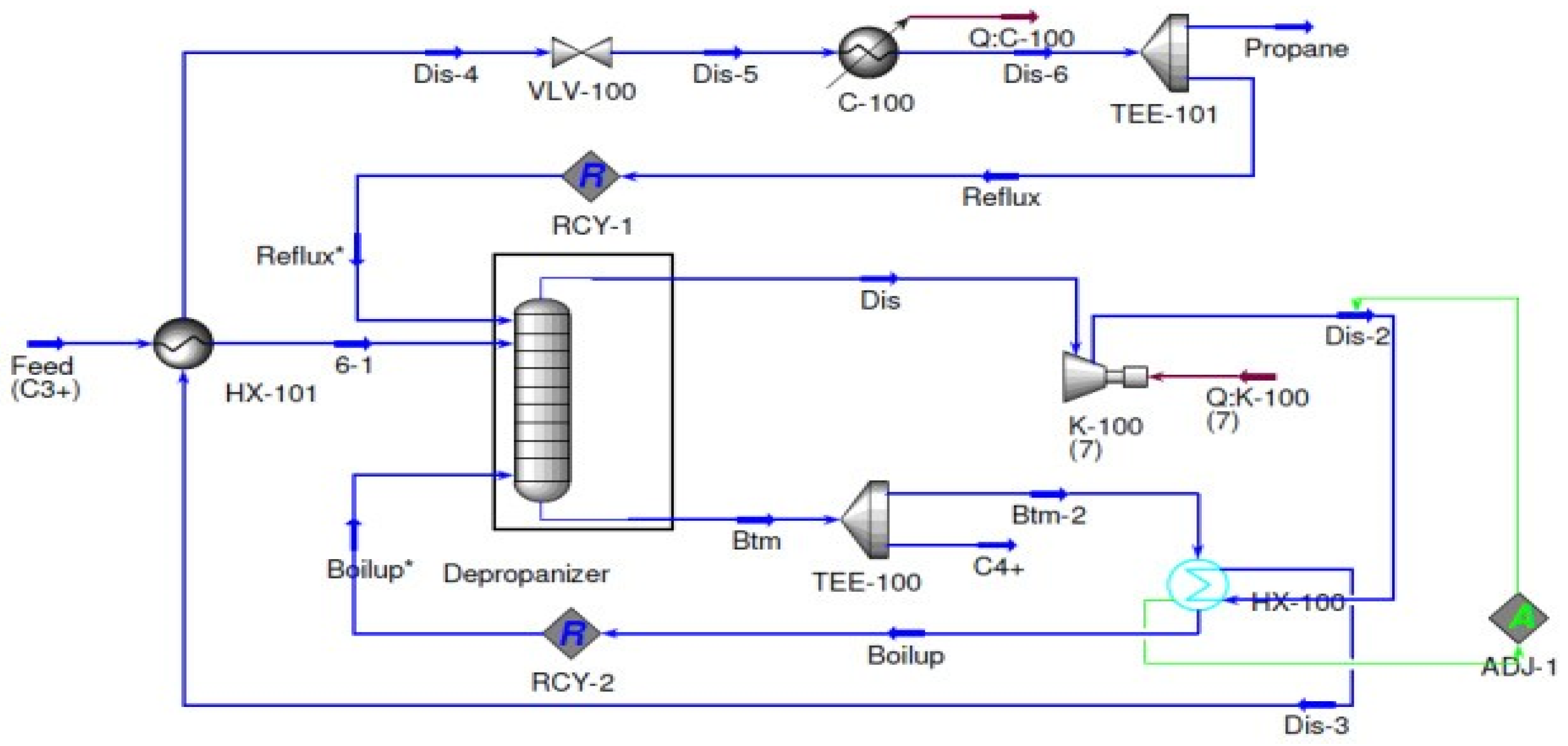
In the TVR (Thermo Vapor Recompression) system, similar to MVR, the distillate is compressed to leverage its latent heat for heat exchange with the bottom product from the column, as depicted in
Figure 4. However, in TVR, a different compression mechanism is employed. Instead of using a compressor like in MVR, a steam ejector is utilized. The ejector in the TVR system operates by utilizing steam as a saturated vapor at a pressure of 41 barg. This steam is effectively employed to compress the distillate, enabling the recovery of its latent heat and significantly enhancing the overall efficiency of the distillation process. By leveraging the latent heat of the distillate, the TVR system optimizes energy utilization and achieves improved separation efficiency, leading to enhanced performance and productivity.
Figure 4.
Thermal vapor re-compression (TVR).
Figure 4.
Thermal vapor re-compression (TVR).
In the TVR system, an adjustment unit is utilized in HX-100 to calculate the precise amount of steam needed by the steam ejector to achieve a minimum temperature approach of 5°C. This adjustment unit plays a crucial role in optimizing the system’s performance and ensuring the desired temperature approach is achieved in the heat exchanger. The heat energy from the compressed stream is then utilized to facilitate the boiling process of the bottom product stream within HX-100. This interaction allows for efficient utilization of the heat energy from the compressed stream, effectively transferring it to the bottom product stream. Following this heat exchange, the condensed stream is recycled back to the column, completing the cycle. This process aids in maximizing energy usage and enhancing the overall efficiency of the distillation system. In order to reach its saturation temperature, the partially condensed stream undergoes additional cooling through the utilization of heat exchanger HX-101 and cooler C-100. These cooling units work together to effectively bring the stream to its desired temperature. Following the cooling process, the water and propane mixture is then separated in the V-100 separator. This separation step is essential for optimizing the distillation system and ensuring the desired product purity is achieved. By effectively separating the components, the distillation system can recover pure propane, which is the desired end product. This separation process plays a vital role in maintaining the quality and purity of the final product, ensuring the distillation system operates at its optimal capacity.
Once the propane stream has been separated, it is further divided into two distinct streams: the end product and the reflux stream. The end product stream consists of the desired purified propane, which can be collected and utilized for various applications. This stream represents the final product of the distillation process and is typically of high quality and purity. On the other hand, the reflux stream is a portion of the separated propane stream that is recycled back into the distillation column. This reflux stream serves a crucial role in the distillation process by providing a liquid phase that descends through the column, aiding in the separation and purification of the desired components. By separating the propane stream into these two streams, the distillation system can effectively control the purity of the end product while maintaining optimal operating conditions within the column.
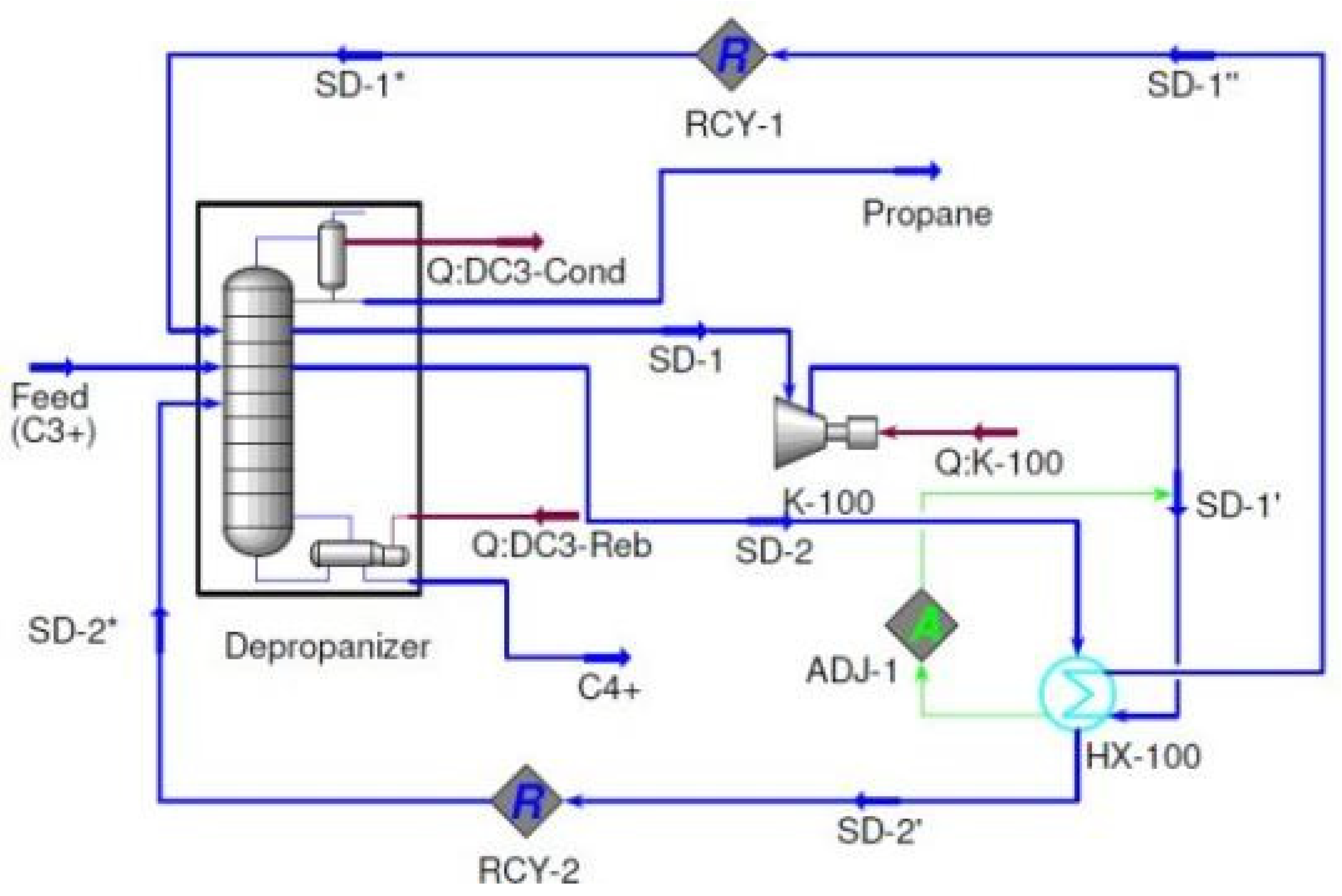
In
Figure 5, the BF (bottoms fractionation) system is designed as an open system, utilizing the bottom product from the column as a refrigerant. The product extracted from the column is divided into two separate streams: the final bottom product and the recycled stream, as illustrated in the figure. The recycled stream is pressurized to match the saturation temperature of the distillate before being reintroduced back into the column. This pressurization process ensures that the recycled stream is at the appropriate pressure and temperature to effectively contribute to the distillation process within the column. By utilizing the bottom product as a refrigerant and incorporating the recycled stream, the BF system optimizes energy usage and enhances the efficiency of the distillation process. This design enables effective separation and purification of the desired components, resulting in the production of the final bottom product while maintaining optimal operating conditions within the system. To achieve a minimum temperature difference of 5°C, the pressure of the valve output is adjusted in the HX-100 unit. This adjustment ensures that the recycled stream, after undergoing heat exchange with the top product stream in HX-100, is evaporated and compressed to match the pressure of the column. This compression is achieved using a compressor. Simultaneously, the partially condensed top product stream is further cooled through additional cooling mechanisms. This cooling process helps to achieve the desired temperature for efficient separation. Following the cooling, the partially condensed top product stream is then separated into two distinct streams: the final step top product and the recycled stream. The separation of the streams allows for the collection of the desired final step top product, which is typically of high quality and purity. The recycled stream, on the other hand, can be reintroduced back into the distillation column to enhance the separation and purification process. By implementing these steps, the distillation system can optimize the separation process and ensure the production of high-quality products while maintaining efficient operation.
Figure 5.
Bottom flashing (BF).
Figure 5.
Bottom flashing (BF).
Figure 6 shows the HYSYS flow diagram for the SHE (Shell and Tube Heat Exchanger) design, which incorporates an intermediary heat exchanger. In this design, the top product from the column undergoes compression and condensation through the utilization of the HX-100 heat exchanger. The pressure at the outlet of the compressor is carefully controlled in the HX-100 heat exchanger to meet the desired minimum temperature difference. This design ensures efficient heat transfer and optimum energy utilization within the system. The intermediary heat exchanger plays a crucial role in facilitating the heat exchange process, enabling the compression and condensation of the top product stream. By carefully controlling the pressure at the outlet of the compressor in HX-100, the system can achieve the desired temperature difference, optimizing the overall performance of the SHE design. This flow diagram demonstrates the effective integration of various components to enhance the separation and heat transfer processes, ultimately improving the efficiency and productivity of the distillation system. Once the condensed stream is pressurized to match the pressure of the column, it is further divided into two streams: the final top product and the reflux streams. The reflux stream is then recycled and reintroduced back into the distillation column. This recycling process aids in maintaining optimal separation and helps achieve the desired product purity. Simultaneously, the intermediate side stream liquid extracted from tray 48 in the column is reheated through reboiling. This reheated stream is then reintroduced into the column at tray 48, utilizing the HX-100 heat exchanger. The heat exchanger facilitates the transfer of heat to the intermediate side stream liquid, ensuring it reaches the desired temperature before being reintroduced into the column. As per the assumed flow rate, the intermediate side stream liquid has a flow rate of 1000 kmol/h. This specific flow rate helps maintain the desired operating conditions within the column and contributes to the effective separation and purification of the components. By incorporating these steps, the distillation system can achieve efficient separation and maintain optimal operating conditions, ultimately leading to the production of high-quality end products.
Figure 6 shows the HYSYS flow diagram for the SHE (Shell and Tube Heat Exchanger) design, which incorporates an intermediary heat exchanger. In this design, the top product from the column undergoes compression and condensation through the utilization of the HX-100 heat exchanger. The pressure at the outlet of the compressor is carefully controlled in the HX-100 heat exchanger to meet the desired minimum temperature difference. This design ensures efficient heat transfer and optimum energy utilization within the system. The intermediary heat exchanger plays a crucial role in facilitating the heat exchange process, enabling the compression and condensation of the top product stream. By carefully controlling the pressure at the outlet of the compressor in HX-100, the system can achieve the desired temperature difference, optimizing the overall performance of the SHE design. This flow diagram demonstrates the effective integration of various components to enhance the separation and heat transfer processes, ultimately improving the efficiency and productivity of the distillation system. Once the condensed stream is pressurized to match the pressure of the column, it is further divided into two streams: the final top product and the reflux streams. The reflux stream is then recycled and reintroduced back into the distillation column. This recycling process aids in maintaining optimal separation and helps achieve the desired product purity. Simultaneously, the intermediate side stream liquid extracted from tray 48 in the column is reheated through reboiling. This reheated stream is then reintroduced into the column at tray 48, utilizing the HX-100 heat exchanger. The heat exchanger facilitates the transfer of heat to the intermediate side stream liquid, ensuring it reaches the desired temperature before being reintroduced into the column. As per the assumed flow rate, the intermediate side stream liquid has a flow rate of 1000 kmol/h. This specific flow rate helps maintain the desired operating conditions within the column and contributes to the effective separation and purification of the components. By incorporating these steps, the distillation system can achieve efficient separation and maintain optimal operating conditions, ultimately leading to the production of high-quality end products.
Figure 6.
Side heat ex-changer (SHE).
Figure 6.
Side heat ex-changer (SHE).
Figure 7 showcases the flow diagram for the IHC (Intermediate Heat Pump and Optimal Side Stream Return) design in the distillation system. This design incorporates both the intermediate heat pump and optimal side stream return principles, which contribute to the overall efficiency and performance of the system. In this configuration, the conventional condenser and reboiler can be observed. However, what sets the IHC design apart is the utilization of a heat pump system in the column through intermediate streams, rather than relying solely on heat exchange processes involving distillate, bottom product, or both, as seen in other configurations. The incorporation of the heat pump system through intermediate streams enhances the heat transfer and energy efficiency of the distillation system. It allows for precise control and optimization of heat distribution within the column, leading to improved separation and purification of the desired components. The IHC design emphasizes the use of intermediate streams to implement the heat pump system, providing a more efficient and effective approach to heat transfer within the distillation process. This design principle helps maximize energy usage and enhances the overall performance of the distillation system. At stage 25, a vapor stream is extracted from the rectifying section of the column with a flow rate of 1000 kmol/h. This vapor stream is then compressed and condensed in the HX-100 heat exchanger before being returned to the column. This process helps maintain the desired operating conditions within the column and contributes to the separation and purification of the components. Simultaneously, a liquid stream with a flow rate of 600 kmol/h is taken from the stripping section at stage 48. This liquid stream is then evaporated in the HX-100 heat exchanger before being reintroduced back into the column at the same stage (stage 48). This step aids in optimizing the separation process within the column and ensures efficient operation. By extracting the vapor stream from the rectifying section and the liquid stream from the stripping section, and then subjecting them to compression, condensation, and evaporation in the HX-100 heat exchanger, the distillation system can maintain the desired temperature and pressure profiles within the column. This helps achieve the desired separation and product quality while optimizing the overall performance of the process.
Figure 7.
Intermediate heating and cooling (IHC).
Figure 7.
Intermediate heating and cooling (IHC).
Figure 8.
Self-heat recuperative (SHR).
Figure 8.
Self-heat recuperative (SHR).
The model utilized in this design is based on the heating and cooling potential of the streams or components involved. Prior to being charged to the column, the feed stream undergoes preheating through a heat exchange process with the compressed top product in HX-101. This heat exchange helps elevate the temperature of the feed stream, optimizing its efficiency within the distillation process. The distillate stream from the column is then separated into two streams: the top product and the reflux streams. These streams play essential roles in the distillation module, contributing to the separation and purification of the desired components. HX-101, which is responsible for compressing the top product stream, aids in warming the feed stream. By compressing the top product stream, heat is transferred to the feed stream, resulting in an increase in its temperature. This warm feed stream is then introduced into the column, facilitating the separation and purification processes. Through the preheating of the feed stream and the compression of the top product stream, the design optimizes energy usage and enhances the overall efficiency of the distillation process. This model prioritizes the effective utilization of heating and cooling potential to achieve optimal separation and product quality.
After being separated from the distillate stream, the reflux stream undergoes further processes. It is first inflated and chilled until it reaches its saturation temperature, optimizing its effectiveness in the distillation process. The compressed reflux stream is then used to reboil the bottom product, helping to enhance the separation and purification of the components in the column. This compression process increases the pressure and temperature of the reflux stream, enabling it to provide the necessary heat for the reboiling process. Meanwhile, the condensed stream from HX-100 undergoes expansion and cooling before being returned to the column. This expansion and cooling process help ensure that the stream is at the appropriate pressure and temperature to effectively contribute to the distillation process. To achieve a minimum temperature difference of 5°C in the heat exchangers, the outlet stream pressures of the compressors are carefully set. By adjusting the pressures, the desired temperature difference can be achieved, optimizing the performance of the heat exchangers and facilitating efficient heat transfer within the system. These processes, including chilling, compression, expansion, and cooling, are all part of the overall design to enhance the separation and purification processes in the distillation system. By carefully controlling the pressures and temperatures, the system can achieve the desired operating conditions and maximize the efficiency of the distillation process.
MSHR (Modified Single Heat Recovery) is an advanced version of SHR (Single Heat Recovery), as depicted in
Figure 9. Unlike SHR, MSHR requires only one compressor, K-100, in its arrangement. In this design, the overhead vapor from the column is compressed by the compressor, which is positioned at the top of the product stream. To condense the compressed vapor, HX-100 is employed. In HX-100, an adjust unit is incorporated to regulate the outlet pressure of the compressor. This adjustment is crucial to ensure that the minimum temperature approach of 5°C is met. By carefully controlling the compressor outlet pressure through the adjust unit, the MSHR design optimizes the heat transfer process in HX-100. This optimization helps achieve the desired temperature difference and enhances the efficiency of the overall system. MSHR offers a more streamlined and simplified configuration compared to SHR, as it eliminates the need for multiple compressors. This design modification enhances the overall performance and energy utilization of the distillation system, contributing to improved separation and product quality.
Figure 9.
Modified self-heat recuperative (MSHR).
Figure 9.
Modified self-heat recuperative (MSHR).
After the compressed vapor stream is condensed in HX-100, it is then passed through HX-101. HX-101 plays a crucial role in the process by providing heat to preheat the supply stream. This preheating step ensures that the supply stream reaches the desired temperature before entering the column, optimizing the efficiency of the distillation process. To match the pressure of the column, the pressure of the condensed stream is regulated by valve VLV-100. This valve helps maintain the desired pressure level, ensuring proper operation within the column. Additionally, the temperature of the condensed stream is controlled by valve C-100 to achieve its saturation temperature. This temperature control is essential for maintaining the desired conditions within the distillation system and facilitating effective separation and purification. Once the condensed stream has undergone pressure regulation and temperature control, it is then separated into two streams: the distillate and the reflux. This separation process ensures that the desired product streams are obtained while enabling the recycling of the necessary reflux stream to optimize the separation efficiency. By incorporating these steps, the distillation system can effectively control the pressure and temperature of the condensed stream, leading to improved operational performance and enhanced product quality.
