1. Introduction
With the rapid development of wireless communication technology in pervasive infrastructure and mobile clients, the demand for LBSs (location-based services) is also accelerating in people’s daily lives. Hence, indoor localization techniques have got great concern in both academia and industry, and various indoor localization techniques have been developed, classified by the dependent infrastructure, such as Wi-Fi [
1] [
2], acoustic signals [
3], UWB [
4], RFID [
5], etc.; by the nature of signals to be measured, such as TDOA(Time Difference Of Arrival), TOA (Time Of Arrival), RSS (Received Signal Strength) [
6], and CSI (Channel State Information)[
7], etc.
In particular, because of the advantages of no need for additional infrastructure, low cost, and high localization accuracy, especially with the rapid development and popularization of smartphone and WLAN infrastructure, indoor fingerprint localization has become one of the focuses of current research. Among all developed indoor localization techniques, the WLAN-based localization method is one of the most popular methods. Which, indoor fingerprint localization is widely popular because it does not require the accurate location of the APs and can fully utilize public WLAN facilities for localization [
8]
. The fingerprint-based indoor localization is usually conducted in two phases, i.e. offline site survey phase and online fingerprint matching phase. Accuracy has long been the primary challenge for indoor fingerprint localization. So far, a lot of study work and achievements have been made in these two phases and many systems, and techniques and technologies have been developed to reduce localization error and improve localization accuracy [
9] [
10].
The multidimensional scaling (MDS) technology is a data dimensionality reduction method widely applied in indoor localization [
11], which employs FDs to represent PDs to construct a distance matrix between nodes to obtain their similarity or correlation, thereby calculating an estimate of TP [
12]. In recent years, with the vigorous development of artificial intelligence (AI) technology, a large number of machine learning have been introduced into indoor fingerprint localization, such as support vector machine [
13], weighted K-nearest neighbor (WKNN) [
14] [
15], and artificial neural network (ANN) [
16] [
17]
, and so on. To deal with high noise in RSSI measurements and ensure high target-localization accuracy, authors in [
13] proposed two range-free target-localization schemes on SVR, one is a plain support vector regression (SVR)-based model and the other is a fusion of SVR and Kalman filter (KF). WKNN has been widely used in indoor localization, for the problem of traditional WKNN not getting high accuracy and having poor stability, the Manhattan distance was introduced in [
14], while in [
15], a combined algorithm based on WKNN and extreme gradient boosting (XGBoost) was proposed. Further, the BP (Back Propagation) neural network is used in [
17] to determine the distances between the TP and each RP to mitigate the effect of fluctuation of RSS. And deep neural network (DNN) model is considered in [
18], where DNN models obtained from multiple training sessions are combined to locate the target, achieving the lower RMSE. In all, it has been proved that machine learning can effectively improve indoor localization accuracy, enhance system robustness, reduce costs, and improve the performance of the indoor localization method [
19].
In addition, a variety of other localization strategies have also been proposed. For example, in literature [
20], a location-aware infrastructure is presented, which can give rise to a sensing mechanism that enables infacility crowdsourcing can help fingerprinting localization services. By the similarity of RSS sequences, the assistant nodes were selected in [
21].to improve the localization accuracy, and by an adaptive Kalman filter, the time-of-flight ranging error has been alleviated. Recently, a fingerprint augment framework based on super-resolution (FASR) was proposed in [
22] to reduce the cost at the offline phase and ensure localization accuracy
. Based on the conversion between fingerprint image and fingerprint data, the framework achieved the fusion of fingerprint augment and super-resolution. A transportable laser range scanner was used to automatically label Wi-Fi scans in [
23] to get an accurate indoor fingerprint localization system with no associated data collection.
For the online phase of fingerprint-based localization, it is widely known that fingerprint matching techniques play an important role in reducing localization errors, and have been developed various techniques [
24] [
25]. It can be seen that many fingerprint-based localization algorithms are based on a common premise, that is to use FD to discriminate PD, while FD is the Euclidean distance of RSSD [
26] [
27]. In [
28], we have discussed that RSSD represents the difference in RSS received by an AP at two different locations, which is closely related to the state of the APs. Nowadays, with the booming development of intelligence, many indoor spaces can receive a large number of AP signals. These APs with high-quality signals are installed for communication, they are evenly distributed and dense, but they are not uniformly managed. That is to say, we do not know the state of most of APs. When we utilize these ubiquitous APs for localization, they will bring greater interference and uncertainty, seriously affecting localization performance.
However, the root cause of localization errors from APs has not been adequately studied. Although researchers in [
29] identified several crucial problems that caused the localization errors, only the different distances of the APs having diverse discrimination capabilities were studied. In [
30], the problem of the impaired APs and the joining of the new APs were considered and a secure fingerprint localization method was proposed for robust variable environments, but it has to rely on a Wi-Fi terminal with a transmitter and receiver module. Although we have analyzed AP’s discrimination capability in [
28], no localization algorithm was provided. Hence, the research of [
28] was extended in this article, a new FDDC-WKNN technique is redefined by combining the policies of improving FD’s discrimination capability to PD and WKNN algorithm, which can provide a solution for the aforementioned problem about APs’ state.
The scenes considered is APs-rich indoor environments and APs’ states are unknown. We conduct a variety of experiments to observe the effects of the various states of APs on localization accuracy, and find that the PD of the pairwise position indicated by RSSD depends on three factors. Then, based on the analysis of the relationship between the RSSD from an AP and a position pair, we provide the corresponding solution policies to improve FD’s discrimination capability to PD from above three factors. At last, we integrated all these perspectives with WKNN in a unified solution and proposed an FDDC-WKNN algorithm.
The main work and contributions of the article can be summarized as follows.
The root causes of limiting the discrimination capability of FD related to APs’ state are investigated. We deeply analyzed and recognized three factors of APs affecting FD’s discrimination capability, which is 1) the distance between AP and the sample position; 2) the AP’s direction to the pairwise positions; 3) the health state of the APs.
For the above three problems, we provided corresponding solution policies to improve FD’s discrimination capability, which include a threshold to eliminate abnormal APs, a discrimination correction quantity, and a priority weight.
Ultimately, by integrating the solution policies with WKNN, we advanced a redefined indoor localization technique, i.e. FDDC-WKNN, which has strong robustness and stability to the state of AP in APs-rich environments without knowing APs.
The rest of the manuscript is organized as follows.
Section 2 introduces the framework of FDDC-WKNN and presents preliminary knowledge and some symbols definitions, and in section 3, we conduct some observation to find APs’ state affecting FD’s discrimination capability and provide corresponding solutions. FDDC-WKNN algorithm process is described in detail in
Section 4, and in
Section 5, extensive experiments and simulations are executed. At last, the conclusions of the article are presented in
Section 6.
2. Indoor Fingerprint Localization Model and Preliminary
In this section, we first introduce the framework of the proposed FDDC-WKNN indoor fingerprint localization system, which is also applicable to other FDDC-based indoor localization systems. Then some preliminary knowledge and symbols definitions are provided to make the expression clearer later.
2.1. The Framework of the Indoor Fingerprint Localization Model
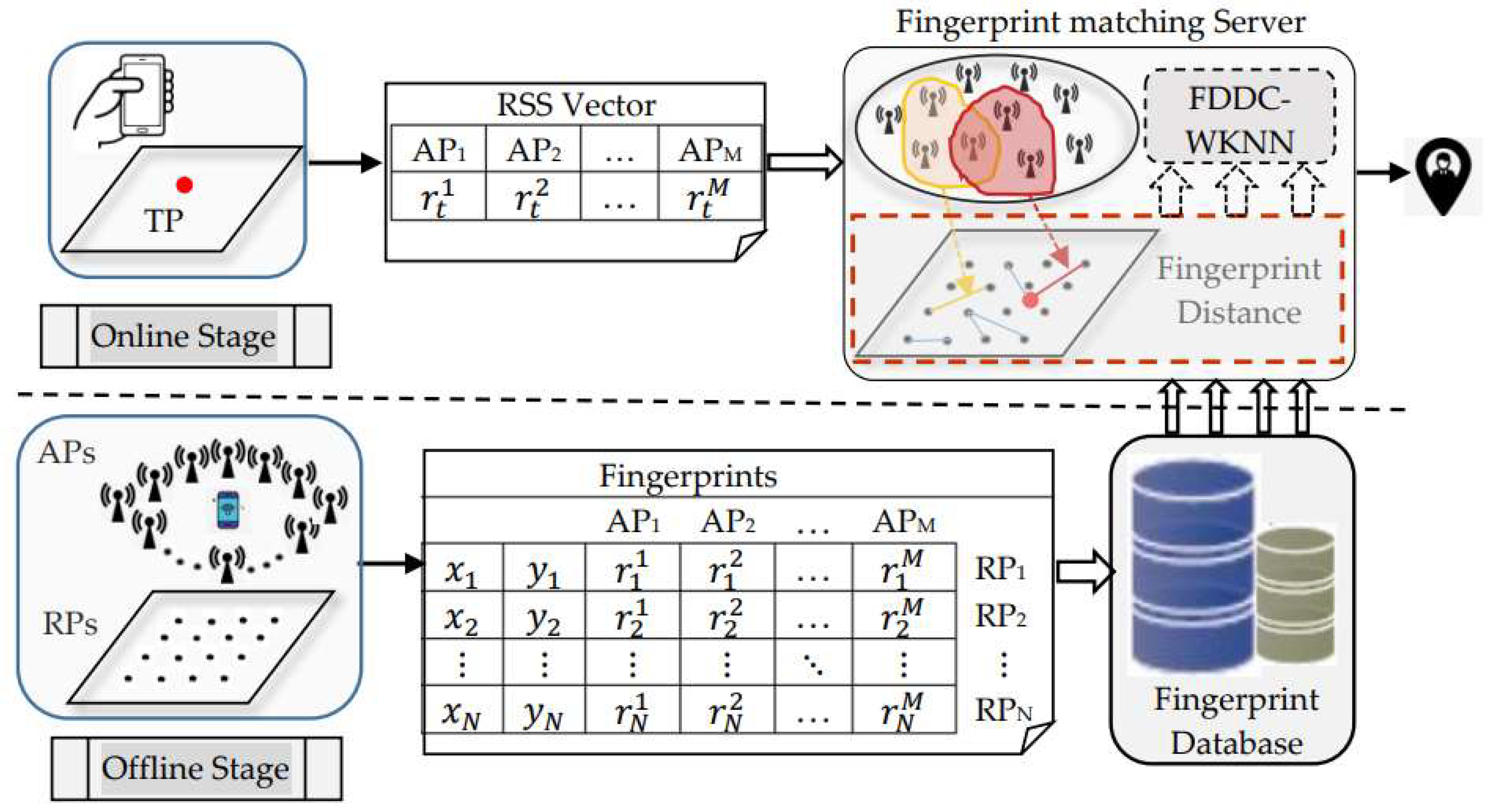
The localization process of a typical indoor fingerprint localization technique usually includes two phases, namely offline site survey and online fingerprint matching. During the offline phase, for each Reference Point (RP), the RSS values from different APs are collected and recorded as an RSS vector. Add the coordinates of the RP to the RSS vector to form the fingerprint of the RP. Finally, the fingerprints of all RPs form a fingerprint matrix and are stored in the fingerprint database. During the online phase, a user sends a RSS vector at a Test Position (TP) to the localization server, through the localization technique based on the fingerprints in the database, the server returns the user’s estimated position.
In this article, we try to improve the WKNN algorithm based on FDs’ discrimination capability enhancement to be a localization technique FDDC-WKNN at the server. The framework of the indoor fingerprint Localization system is shown in
Figure 1.
2.2. Preliminary
For the convenience of subsequent expression, preliminary knowledge and some important symbols definitions used in the article are described and introduced in this section.
2.2.1. Log-normal Distance Path Loss Model
Theoretically, RSS decays logarithmically with propagation distance in terms of the propagation law of wireless signals. That is, when the transmitter sends a signal to the receiver, the path loss at the receiver ends logarithmically with the distance between the transmitter and the receiver. Here, to express signal propagation loss in a complex indoor scene, the Log-normal Distance Path Loss model is considered, see Formula (1), and then, the received signal strength at the receiver can be gained by Equation (2).
Here, all distances are measured in meters and the parameters in (1) and (2) are explained as follows.
: the distance from the transmitter to the receiver;
: the received signal strength at the receiver;
: the path loss at the receiver;
: the reference distance, usually 1 m;
: the path loss at the reference distance;
: the path loss exponent, i.e., the growth rate of path loss with distance which is based on the different environments and building types. mostly between 2 and 4.
: Gaussian noise, denotes the complex indoor environment effects.
and is the transmitter’s transmission power.
2.2.2. The Standard for Measuring the Relationship Between Two Vectors
Since utilizing FD of pairwise positions to discriminate the PD between them is a prerequisite for indoor fingerprint localization technologies, it is necessary to discuss the discrimination capability between two vectors, which means that we need to know under what conditions one vector can be used to represent another vector well. Here, two criteria are considered, that is correlation and consistency. Next, let two vectors be denoted as and , respectively.
In the field of natural sciences, the Pearson correlation coefficient between two variables is widely used to test the degree of correlation, with a value varying from -1 to 1. If the coefficient is between 0.8 and 1.0, the relationship between the two variables is a very strong correlation, and if the coefficient is between 0.6 and 0.8, the relationship between the two variables is a strong correlation. For
and
, the Pearson correlation coefficient can be calculated by Formula (3). then the coefficient can be used to imply the correlation between FDs and PDs, and it is reasonable to be used to indicate the degree of linear correlation between them.
where
and
represent the mean values of
and
, respectively.
Besides, it is reasonable that if the
is greater than
, the corresponding
should also be greater than
, which can be called the degree of a data sequence. Similarly, if the consistency is between 0.8 and 1.0, the relationship between the two variables is a very high consistency, and if the coefficient is between 0.6 and 0.8, the relationship between the two variables is a high correlation. Usually, the consistency coefficient of
and
is defined as:
where
From the above formula, there are some unreasonable situations for indoor fingerprint localization techniques. For example, if the PD of two positions is equal while the RSSD is very small, it is reasonable and practical to consider the data sequence between them to be consistent, but it is not consistent with the above formula. In this article, we use the modified formula of consistency coefficient in [
28].
The aforementioned double coefficients are mainly used to test the relationships between FDs and PDs. In case the relationships have a very strong correlation and very high consistency, by adopting FDs to discriminate PDs in the indoor localization method, not only the uncertainty of signal propagation in the complex indoor environment can be greatly reduced, but also the localization accuracy can be improved and the localization error can be reduced.
2.3. Symbols Definitions
For one position
with coordinate
, the RSS vector collected from
APs is represented by
where
is the RSS value that is received from the
-th AP. Combining the position coordinates and the RSS vector, we can get the fingerprint
of the position
:
For the pairwise positions consisting of two different positions in the indoor localization area, whose RSS vectors are and respectively, and whose coordinates are and respectively, define the following variables.
where indicates the RSSD of the -th AP at positions and .
Obviously, .
FD of the pairwise positions (
i,
j):
Noted that, from Equation (10), it can be seen that the contribution of different RSSD to the discrimination capability of FDs is different. The bigger contribution of the RSSD means the more suitable AP is selected.
In order to measure the whole discrimination capability of the FD to the PD in the localization area, the whole FD vector and PD vector are defined. For the fingerprint of
RPs in the fingerprint database, write the PD vector of all pairwise positions as:
Similarly, the FD vector of all pairwise positions is:
In this article, the relationships between vectors and are measured in the correlation and consistency, which are used to measure the discrimination capacity of FD against PD.
3. Observation and Enhancement Policies for AP’s Discrimination Capability
In the current highly developed social environment of information technology, our smart devices can easily receive high-quality signals from a dozen or more APs in public indoor environments.
These abundant APs are usually installed for the function of communication by different individuals, which are located at various positions and have various states including removed, impaired or unstable, etc. If there exist abnormal APs, it will inevitably lead to wrong FDs of pairwise positions, resulting in large localization errors. Therefore, utilizing such abundant existing APs to select the suitable APs to improve the discrimination capability of FD has become an important factor affecting localization accuracy.
From the definition of FD, we have to emphasize the discrimination capability of an AP’s RSSD to fingerprint a specific position. So, next, according to an in-depth analysis of the discrimination capability of a single AP to a position pair, we aim to provide different AP RSS correction and selection ways, to greatly improve the discrimination capability of FD to a PD.
3.1. Observations for Discrimination Capability
Indoors, signal attenuation and RSS fluctuation are severe, which are caused by signal reflection and refraction, or multipath fading and indoor noise. Especially, they are closely related to the current environment. Hence, RSS is seriously affected by the indoor environment. In addition to the above factors, due to the influence of the distance, direction and states of the APs, it often occurred that the identical RSSD implies different PD between two positions.
In this article, the term discrimination capability is used to describe one AP’s contribution to FD’s capability to distinguish the PD of pairwise position.
3.1.1. Diverse FDs’ Discrimination Capability Caused by Different Distances APs
It can be seen from Formula (2),
which indicates that
, where
is the RSSD and
denotes the corresponding distance difference. In other words, an identical
means a larger PD difference
at a farther position, or a smaller
at a closer position. Similarly, an identical
means a bigger RSSD
at a closer position, or a smaller
at a farther position.
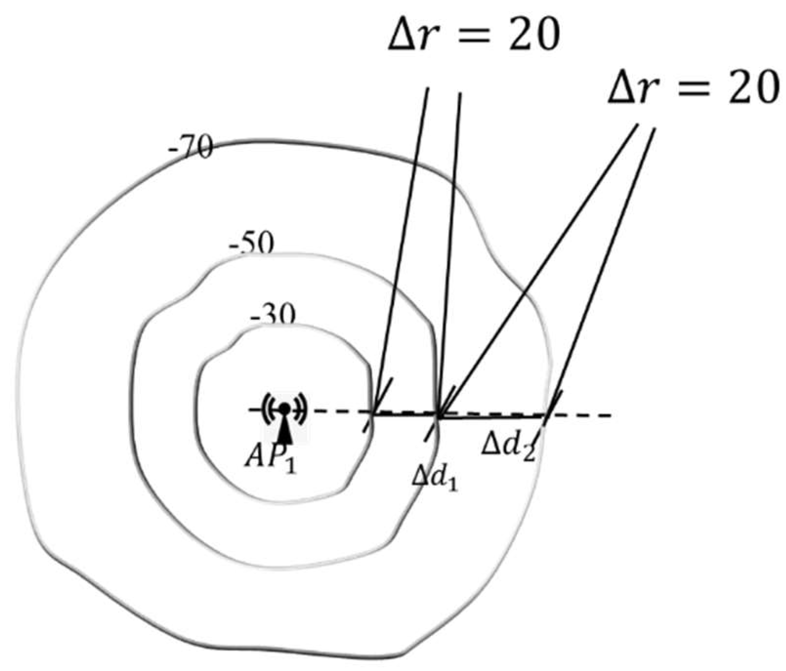
Figure 2 illustrates the RSS spatial distribution. It can be seen that the same RSSD of
corresponds to the different difference in PD of two pairwise positions, depending on the distances of the specific AP.
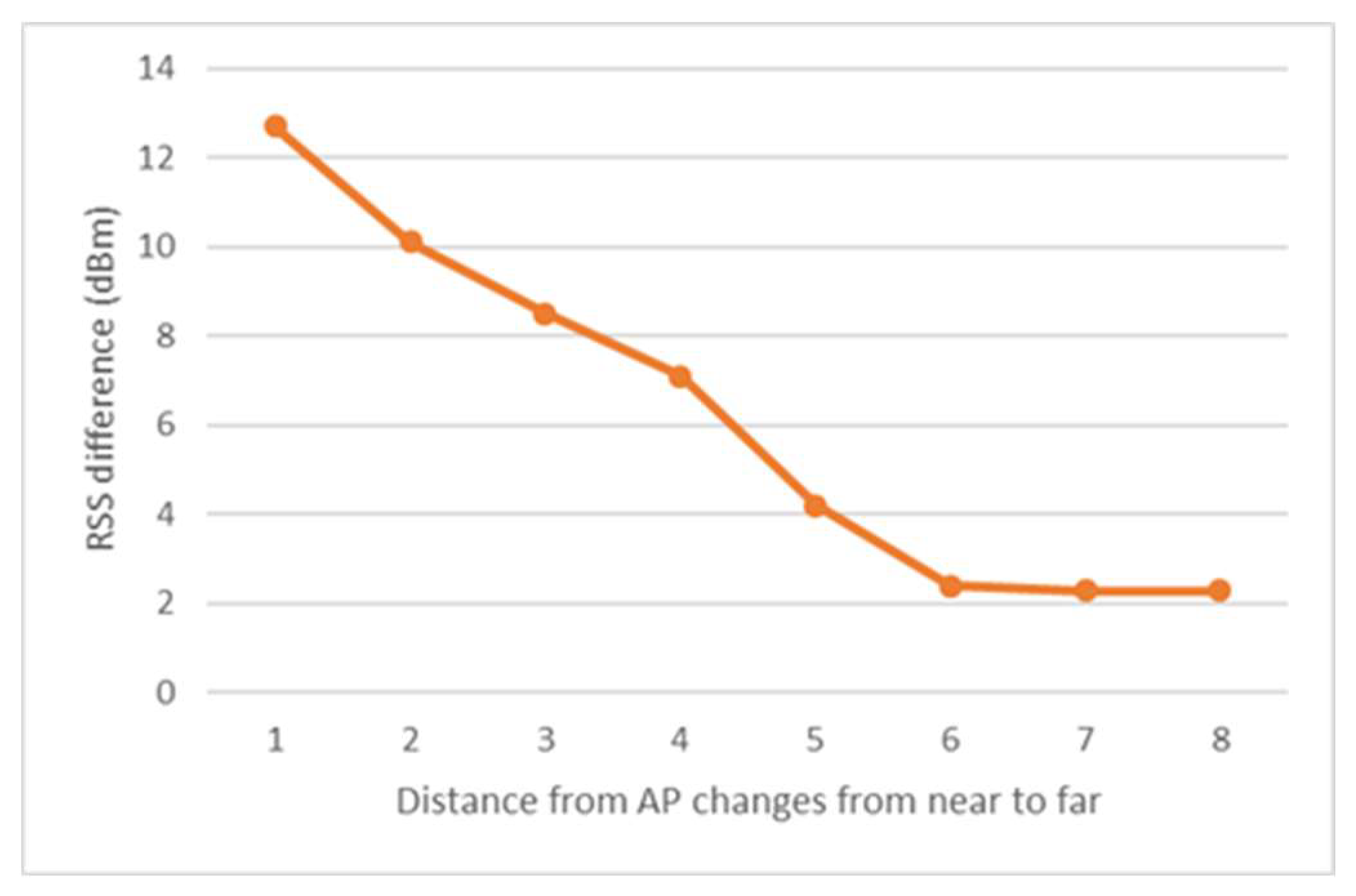
In order to display the effect of the change of AP distance to discrimination capability, for the identical
at a different distance from an AP, the correspondence
values are shown in
Figure 3.
In a word, the PDs of pairwise positions indicated by RSSDs depend on the receivers’ distance, leading to varying discrimination capability for various positions.
3.1.2. Diverse FDs’ Discrimination Capability Caused by APs of Different Directions
Inherent constraints constrained by the law of radio signal propagation; APs have diverse discrimination capabilities to different pairwise positions. That is, an identical
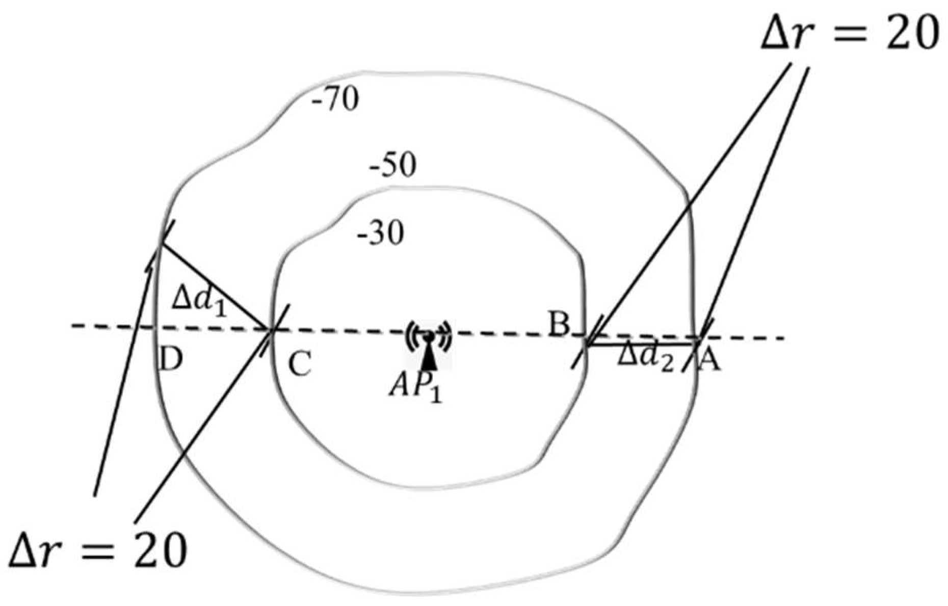
can imply various PDs, see
Figure 4., for any two positions, one is on the ring with RSS=-50dBm, and the other is on the ring with RSS=-70dBm, the value of RSSD
is always 20, but the PD between them varies greatly. According to simple geometry, it’s easy to know that the PD of position pair
is the smallest and
is the biggest. Meanwhile, the most accurate discrimination capability of RSSD
should be for position pair
, which is related to the direction of the APs.
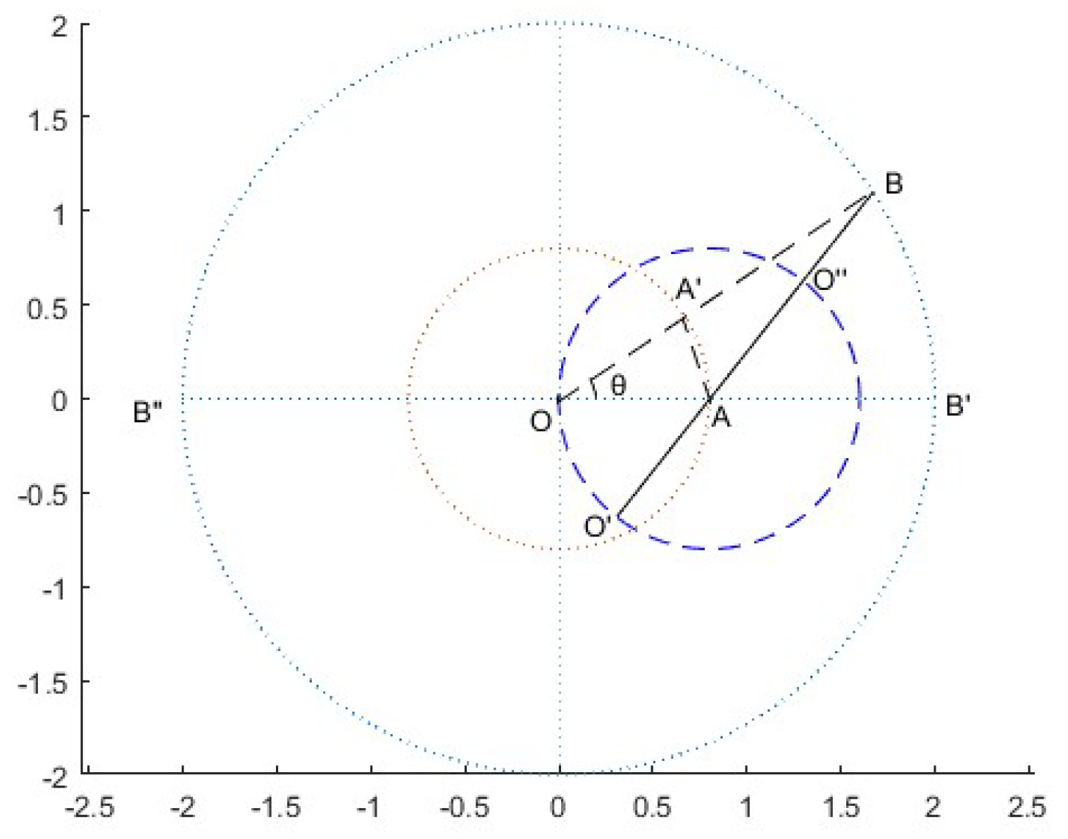
In other words, see
Figure 5, assume that the pairwise position
is fixed, i.e.
(
is a constant). Take position
as the center, and make a circle with a radius smaller than
of
. Suppose an AP is located at
O, then
is also a constant and
, with
as the center, drawing two circles with a radius of
and
, respectively. Connecting
and
, which will intersect with the two circumferences at points
and
, respectively, and
is the included angle between
and
.
It is obvious that
changes with the location of the AP, but the correspondence between the RSSD
and radius difference
remain unchanged, so set
. Therefore, by studying the relationship between
and
, we can get that when the orientation of AP changes concerning the position pair, the corresponding discriminate capability of RSSD changes rules. For
, the following equation is gained:
.
We can obtain that the same value
corresponds to different
, depending on the angle
between line
and
, which means APs at different directions have different discrimination capabilities for the same position pair
. As seen from
Figure 5., when one
is located at point
and point
, the discrimination capability of RSSD is optimal and poorest for position pair
.
Remark that if is a very small value, which means that the space between and point is tiny enough, is about equal to the PD . Then, the RSSD can characterize all PDs well.
In a word, the PDs of the pairwise positions indicated by RSSDs depend on the receivers’ direction, leading to varying discrimination capability for various directions.
3.1.3. Diverse FDs’ Discrimination Capability Caused by APs of Different Health States
In order to make the localization more accurate, in addition to the above two aspects, the unstable APs should not be ignored. The unstable APs can be roughly divided into slight abnormality and complete failure (such as broken/removed/newly emerged). Slight abnormality means that the AP can transmit, but due to the device being impaired, the signal transmitted by the device is weak or unstable. Here, considering the complexity and variability of the indoor environment, for the obstruction of the new facilities or walls results in the weak signal of an AP at a specific location, we also treat the AP as slightly abnormal at the position. For complete failure/removed/newly emerged APs, it means that the device cannot transmit signals at all.
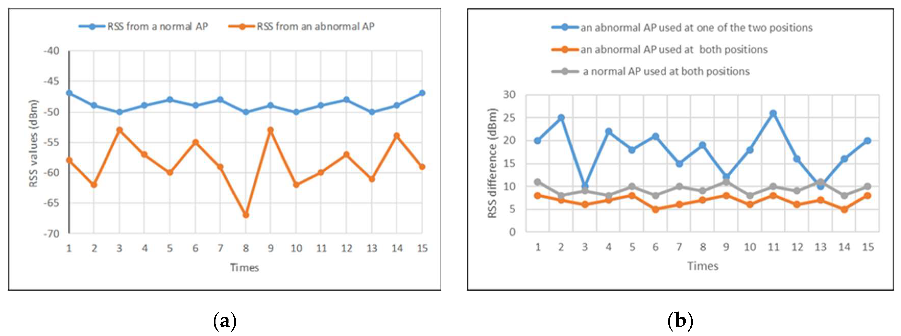
In order to observe the effect of normal APs and abnormal APs, we carry out an experimental analysis of the RSS values of a specific position and the RSSD of a position pair. First, for the sampling position that is fixed 3 meters away from AP, we sample RSS values from a normal AP and an abnormal AP respectively, results shown in
Figure 6 (a). From the figure, it can be seen that the RSS values of the abnormal AP are obviously lower than the RSS value of the normal AP. In addition, the RSS values of the abnormal AP are extremely unstable compared to the values of normal AP. Second, for the sampling position pair with 2.5m PD, we calculate the RSSD of the position pair, see
Figure 6 (b). As seen, when the AP sampling at one position is normal and at the other position is abnormal, the RSSD is obviously larger than that of normal AP and they are extremely unstable. When the AP sampling at both positions is abnormal, the RSSD is slightly smaller than that of normal AP and can be ignored when calculating FD.
In a word, the PDs of pairwise positions indicated by RSSDs are closely related to the AP’s state, leading to diverse FD’s discrimination capability for different healthy states.
3.2. FD’s Discrimination Capability Enhancement Policies
In this section, different discriminatory policies are discussed based on the above discussion and analysis. we first discuss the strategy to identify the abnormal APs.
3.2.1. Abnormal APs Identification
Duo to abnormal APs is the main cause generating big errors in indoor fingerprint localization, we have designed two policies to reduce the impact of abnormal APs, one for slight abnormality APs and the other for complete failure/removed/newly emerged APs.
Since the abundance of APs in the indoor environment and the possibility of abnormal APs, it is unnecessary and also unrealistic to utilize the RSSDs of all APs equally. Whether for the fingerprint in the fingerprint database or online collected the RSS of TP, set a threshold for RSS values to exclude APs with weak signal strength.
For position
, the RSS vector collected from
APs is
, the RSS value
is defined as:
where
is a threshold, only the RSS values of APs with RSS values greater than
will be used to participate in the following steps, otherwise, RSS values will be set to 0. Through this method, slightly abnormal APs with small RSS values (
) in the environment can be eliminated. Furthermore, from Equation (8) and (10), we can find that the component
of RSSD directly impacts the FD
. An AP is normal at one position but is a complete failure or removed or newly emerged at the other position, which can generate a significant
and affect the discrimination capability of FDs. To avoid this situation, make the following rule for
:
We assume that there always exist rich APs in indoor scenes, then through the above policies, abnormal APs, especially the complete failure or removed or newly emerged APs in the environment can be eliminated almost.
3.2.2. Discrimination Correction Quantity
Here, we define a impact factor to quantitatively differentiate the RSSD of each AP for a specific position pair. Since a position pair includes two specific positions, the discrimination factor relates to the impact of AP at each position, it is necessary first to quantify the impact of each AP at each location which we term as an impact factor, and then to define correction quantity based on impact factor.
According to the LDPL model (2) and the estimation of PDs between AP and a position, for the
k-th AP to the
i-th position, the impact factor is calculated as follows:
where
is the estimated distance between the
k-th AP and the
i-th position.
Considering that a certain AP has a large RSS value due to RSS fluctuation, which makes the other representative APs negligible, we introduce the way in literature [
28] to redefine the impact factor. For coding with noisy RSSs, the impact factor is adjusted as follows:
where
is a flexible value, it can be given by empirical, e.g., -50dBm,
and
are constant parameters, which can be determined based on
such that
is continuous at
.
From formula (17), because the reciprocal of PD is consistent with the monotonicity of the LDPL model, the basic rule is that the closer APs are, the stronger RSSs are. Due to the RSSD is the difference of RSS values between two positions, considering the uncontrollability of AP states in indoor environments, we believe that the larger the RSS, the greater the interference for RSSD. Therefore, the correction quantity is defined as follows.
where
is a constant between 3dBm-6dBm, according to the environment conditions, approximately equal to the value of signal fluctuation at a position.
3.2.3. Priority Weight
From Formula (13) in section 3.1.2, we can gain a rule: for APs in different directions, the smaller the angle
, the larger the RSSD
, and the stronger the discrimination capability of FD, which means that the APs who get the larger RSSD has greater contribution to FD’s discrimination capability. Therefore, we grant each RSSD of each pairwise position a priority weight
as follows, which determines the priority and contribution of its participation in FD, see Equation (19). As seen, the larger RSSD corresponds to a higher priority weight.
It is clear that is the S function of , so adding to RSSD will not have a significant impact on the value of FD, avoiding affecting localization accuracy.
Overall, through the above provided discrimination capability improved policies, the APs with large contributions to FD’s discrimination capability will be involved in the calculation of FD, and the more suitable the APs, the higher the degree of participation. Hence, FD with strong discrimination capability to PD is obtained, providing a guaranteed prerequisite for relevant fingerprint matching algorithms.
4. WKNN and FDDC-WKNN Algorithm
4.1. The Idea of KNN and WKNN Algorithms
The K-nearest neighbor (KNN) algorithm is one of the most widely used fingerprint matching algorithms. The idea of the KNN algorithm is to select the positions of K fingerprints closest to the current positional fingerprint to estimate the current position, which is simple, intuitive, and effective. KNN is one of the algorithms that use FD of pairwise positions to discriminate PD between them.
We assume that there are n RPs in an indoor area, and
fingerprints were collected in the offline phase, which is denoted as
, where
, see Equation (6) and (7). In the online phase, the RSS vector of a TP is
. First, calculate all FDs
from position S to RPs; second, select
K nearest RPs based on all FDs; finally, use the following Formula (20) to get the estimation value of S coordinates:
The above formula indicates that the KNN algorithm sets the same weight to all K nearest neighbors. However, according to the propagation characteristics of indoor signals, it is known that the farther the distance, the stronger the signal fluctuation. For this reason, the WKNN algorithm sets different weights based on FD to emphasize that close neighbors contribute ability more, the estimation value of S coordinates can be expressed as follows.
where
is the weight related to distance. In this article we adopt the WKNN algorithm to be the indoor fingerprint algorithm, and the weights are given in the following formula.
Note that: Different K values mean that the number of nearest RPs selected is different, which can affect the accuracy of localization. The optimal K value often gained from experience or practice
4.2. The FDDC- WKNN Algorithms
Taking into account all the strategies and WKNN idea discussed above, a uniform WKNN solution based on improving FD’s discrimination capability will be presented in this section, that is FDDC-WKNN. The presence of a large amount of abundant AP in the indoor environment is a prerequisite for this solution.
For an indoor area, given that there are N RPs and M APs and fingerprint databases have been built on the Server. In the online phase, when we have the RSS vectors at a TP, send them to the server, and want to get the TP location . Based on the policies aforementioned, the algorithm steps on the server side are given as follows.
Step1. Set a threshold
, modify the RSS value in
and the fingerprint data in dataset by Formula (14), and combine
and the RSS matrix of the fingerprint to a new matrix
as follows, where the first row of
is RSS vector
at TP, and the other
rows are RSS matrix at RPs.
Step2. Calculate discrimination factor
for each RSS value and gain discrimination correction quantity matrix
as follows.
where
Then, we gain the correction quantity by
times
and further calculate modified RSS data by
minus discrimination correction quantity matrix
, see Equation (26). Here,
can be seen as the RSS value corrected by the discrimination factor.
Step 3. Calculate the RSSD of the TP to each RP, that is subtract each remaining row of the matrix
from the first row to obtain each RSSD vector
, then, an RSSD matrix is gained as follows.
where
Step4. Use priority weight Formula (19) to calculate all priority weight of
, we can get the following priority weight matrix
.
where
Then, calculate the Hadamard product of
and
, that is multiply the corresponding elements of
and
as Equation (30). Then, we get the weighted RSSD
by priority weight.
where
Step 5. Calculate the FD of TP to each AP by Formula (10) to obtain an FD sequence
and expressed by following Equation (32).
where
Step6. Select the smallest K elements in sequence and calculate their weights according to Formula (22). Furthermore, according to Formula (21) to get the position of TP.
In addition, in order to obtain the correlation and consistency between PD and FD in subsequent experiments, we need to calculate the PD of TP to each AP by Formula (9) to obtain an PD sequence
and expressed as follows.
where
5. Simulation and Experiments
In this section, we will evaluate the policies and algorithm proposed in this article by conducting some experiments in two scenes, that is simulation environments and real environments.
In particular, our technology is suitable for having a large number of APs in both scenes and there are phenomena such as APs being damaged, malfunctioning, or removed, etc.
5.1. Scenes Setup and Some Parameters Presets
Firstly, the setups and some presets of simulation and real scenes are introduced, respectively.
5.1.1. Introduce for Experimental Scene
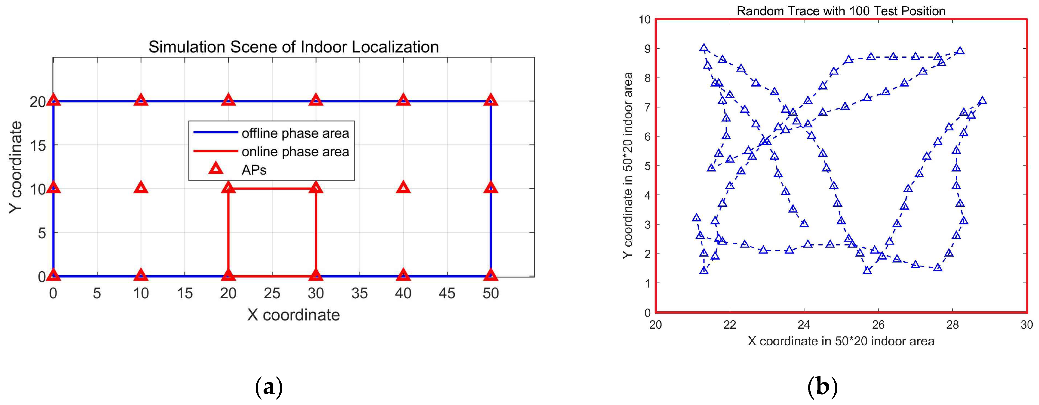
To simulate large-scale indoor space with rich APs, we simulated a 50 * 20 sized indoor area with 18 APs, and these APs are placed on grid points every 10 meters in the simulation area, which is depicted in
Figure 7 (a). In our simulation process, RSS data are generated by ray tracing technology based on the LDPL model while considering wall reflection and noise indoors. Initially, we generated a simulation fingerprint dataset at position with an interval of 0.1m. Then we can get any offline fingerprint database from the dataset as needed. For example, an offline fingerprint database with an RPs interval of 1 m only needs to take values every 10 position points in the dataset, that is, 10 * 0.1=1m, and so on.
In our following simulation experiment, the offline fingerprint database is from the above fingerprints dataset by setting the RPs interval of the offline database to 1 m, that is there are 51*21 = 1071 RPs in the simulation area.
In the online phase, we simulated a target moving in a 100 square meter room in the simulation area (see the red rectangle in
Figure 7 (a)) and obtained a trace with 100 trajectory points, as well as RSS on each trajectory point, see
Figure 7 (b). Meanwhile, we simulated two abnormal APs, one of which was removed or broken, and the other had a minor malfunction These 100 trajectory points are used as TPs for the indoor localization algorithm. In order to simulate people’s living habits, the movement trajectory moves in space within 1 meter of the boundary.
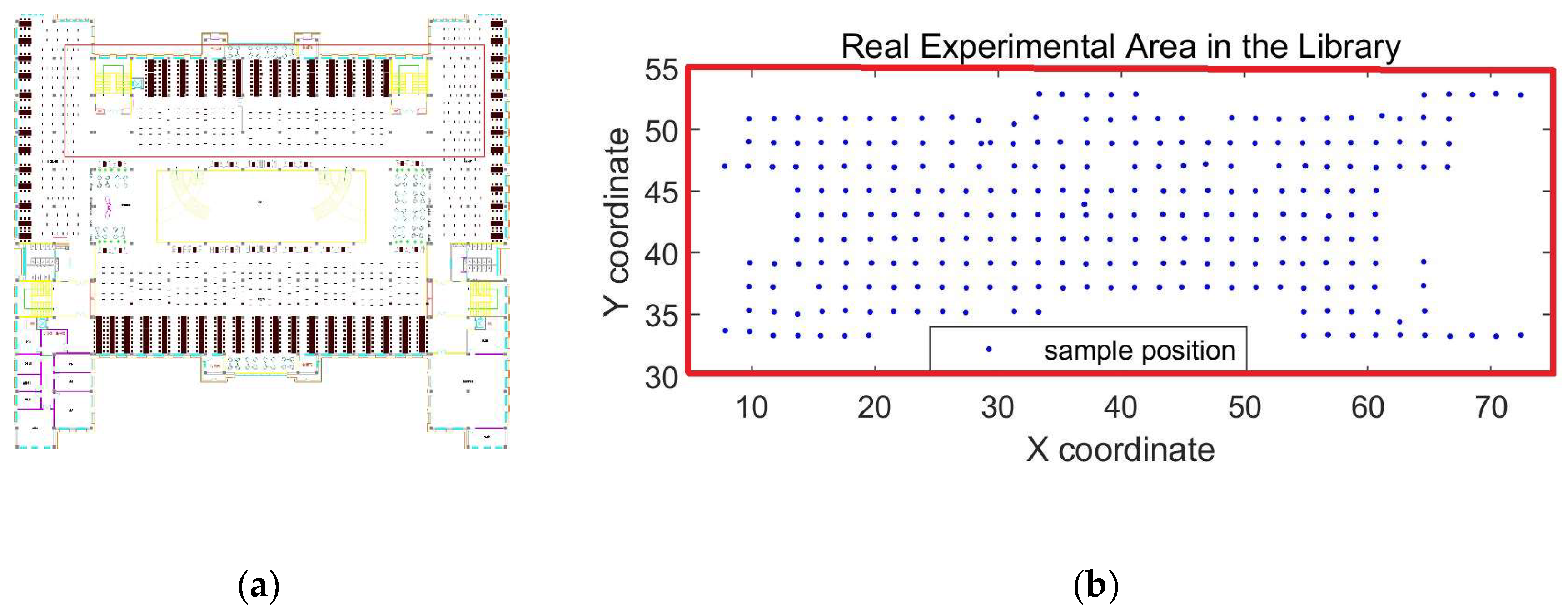
The real experimental scene was on the second floor of the school library in Dalian University, and the plan of which is shown in
Figure 8 (a). The central position of this floor is the vacant part on the first floor, surrounded by an open bookshelf reading area, including a large number of open bookshelves and reading tables and chairs. The experiment area is located on the north side of the floor with about 1200
m2, in the red rectangle area of
Figure 8 (a), and
Figure 8 (b) is the enlarged experiment area, as can be seen, there are 261 RPs at an interval of 2m. In addition, there are a total of 83 APs that can work in the experimental area.
In the offline phase, we used HUAWEI P9 smartphone to sample RSS from 83 APs to build a fingerprint database. In the online phase, to reduce the workload of data sampling, we randomly selected 50 points from these 261 to be TPs and set 8 abnormal APs with 4 APs removed or breakdowns and 4 APs with slight abnormality.
Overall, in order to have a clearer understanding of the two scenes, the setups for both scenes are shown in
Table 1.
5.1.2. Parameters Presetting
In the proposed algorithm, many parameters need to be set to experiment. Here, considering the environments of two scenes, the parameters are determined based on depending on experience or specific conditions respectively, as listed in
Table 2.
Due to the RSS being sampled directly in the real scene, the first three parameters are not required to be set.
5.2. Simulation and Analysis
Aiming to measure whether the proposed policies can improve the whole discrimination capability of FD to PD, we conducted some experiments to verify the correlation and consistency changes between FD and PD before and after using FDDC-WKNN. For the simulation environment, we first verified the effect of proposed policies on the discrimination capability of FD to PD. Then, for a random trace with 100 positions, we find the optimal value of K, and with the optimal K, we simulate the localization positions and derive the CDF curves to demonstrate the localization performance.
For the real scene in the Dalian University library, we also find the optimal value of K for 50 random TPs, and with the optimal K, we gain the localization results similarly.
5.2.1. Discrimination Capability of FD to PD
By calculating PD sequence
by Equation (35) and FD sequence
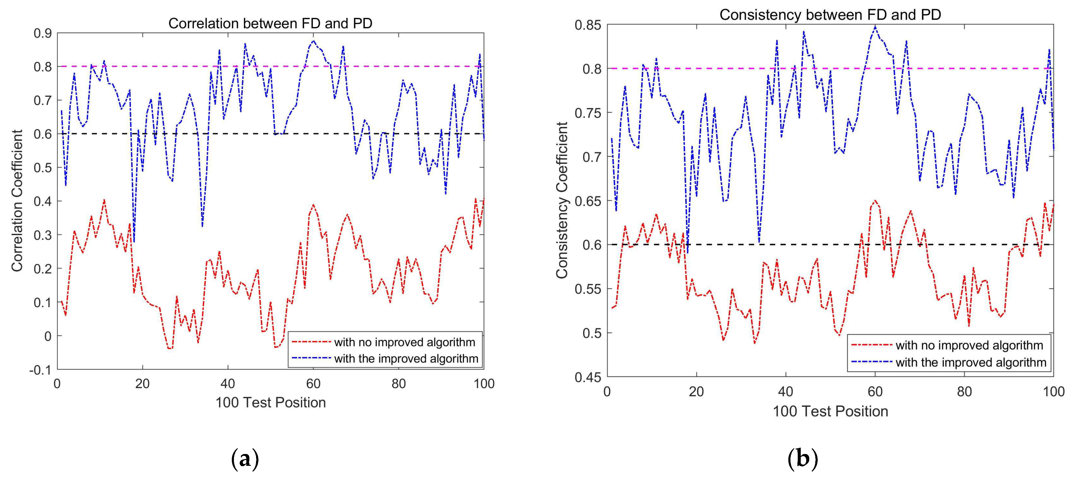
by Equation (35) between 100 TPs and 81 RPs in the localization area, we gain the correlation coefficient and consistency coefficient between each TP and RPs. From the results shown in
Figure 9, we can see that both the correlation coefficient and the consistency coefficient are greatly improved. After implementing the policies proposed in this article, strong correlation increased from 0 to 76%, and consistency increased from 26% to 99%, which indicates the discrimination capability of FD to PD has been greatly improved.
To further examine the impact of abnormal AP on FDs’ discrimination Capability, we repeated the experiment of calculating
and
under diverse abnormal AP conditions to obtain the correlation coefficient and consistency coefficient between PD and FD. For clarity, the experimental conditions are recorded as following situations, and the results before and after implementing FDDC_WKNN are displayed in
Table 2.
Ⅰ: All APs are in a normal state
Ⅱ: There is one slight abnormality AP
Ⅲ: There is one complete failure AP
From the results in
Table 2, it can be seen that the presence of completely failed APs in the localization area has the greatest impact on the correlation and consistency between FD and PD. Moreover, regardless of the conditions, the policies proposed in this article have improved the correlation and consistency between FD and PD to varying degrees.
Table 2. Correlation and consistency between PD and FD before and after implementing the proposed policies.
Table 2. Correlation and consistency between PD and FD before and after implementing the proposed policies.
| |
Ⅰ |
Ⅱ |
Ⅲ |
Ⅱ&Ⅲ |
| Strong Correlation |
16% |
91% |
16% |
89% |
0 |
78% |
0 |
76% |
| High Consistency |
72% |
99% |
78% |
99% |
27% |
99% |
26% |
99% |
5.2.2. Setting of K
In the same conditions of localization area, different K values in FDDC-WKNN can lead to different localization accuracy. We assumed that the K value with the lowest average errors is optimal. The optimal K value is usually not fixed and varies depending on the environment. We compared the average Errors under different K values for both simulation and real scenes to obtain the corresponding optimal K value.
As shown in
Figure 10, the optimal K value is 7 in the simulation scene and 6 in the real scene. However, we found that the average localization errors did not change significantly with different K values, as our policies have greatly improved the FD’s capability to discriminate PD, thereby reducing the impact of K value changes.
5.2.3. Localization Examination by FDDC-WKNN under the Optimal K
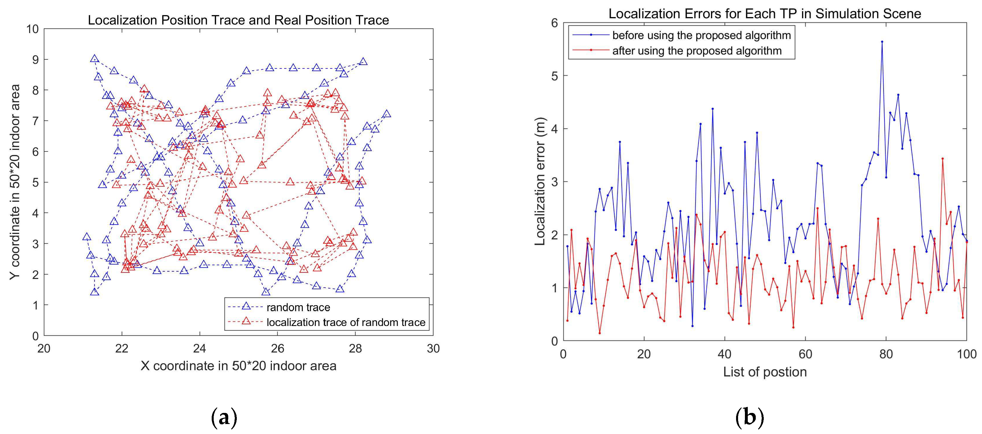
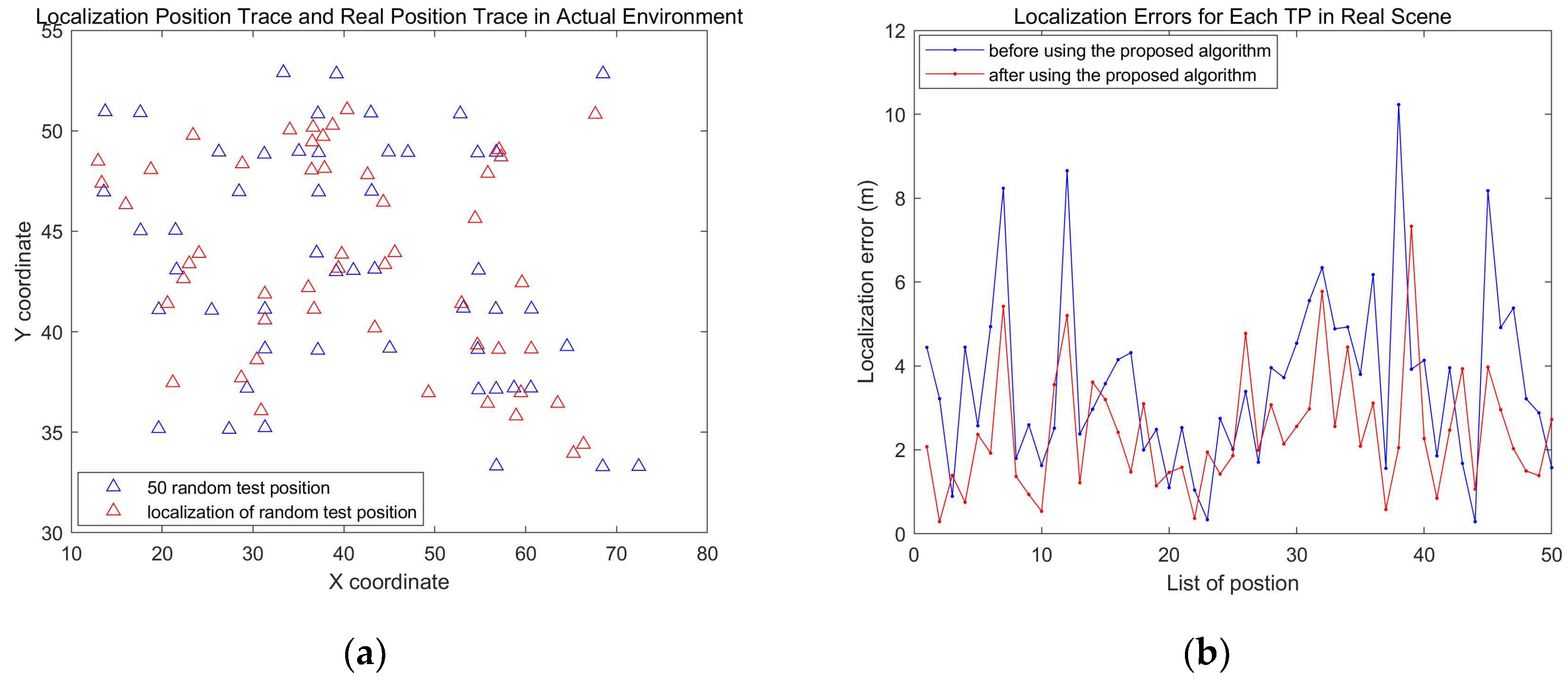
For
in the simulation scene with 100 TPs and
in the real library scene with 50 TPs, we apply the FDDC-WKNN algorithm, and the localization results are demonstrated in
Figure 11 and
Figure 12, respectively.
In the simulation scene, before using FDDC-WKNN algorithm, due to the influence of abnormal APs, the localization errors were large and fluctuated greatly. Based on the FDDC-WKNN algorithm, it can be seen from
Figure 11 (b) that the localization errors have significantly decreased and are basically stable.
In the real library scene, the localization results are basically consistent with the simulation scene, see
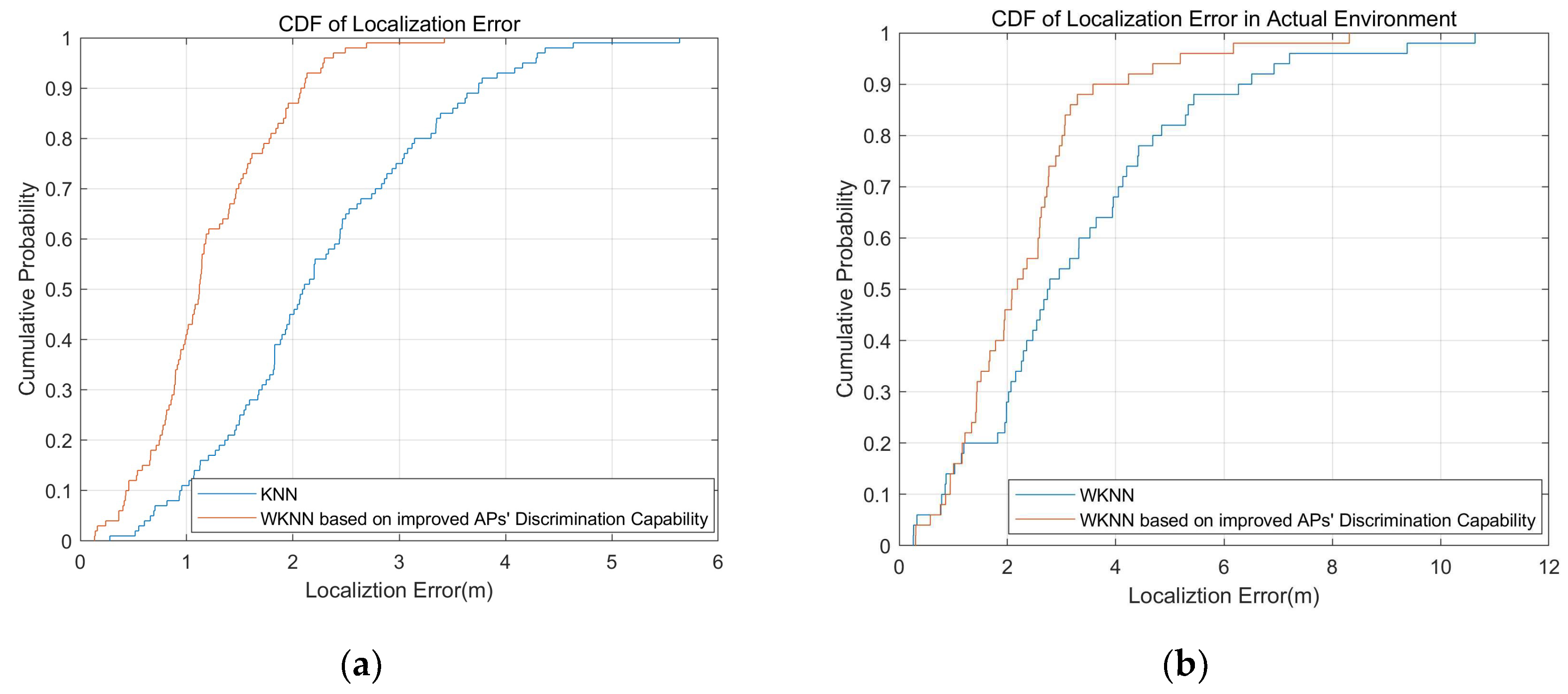
Figure 12, but due to the complexity and variability of the real environment, the localization errors are larger and the error fluctuation is also greater. Moreover,
Figure 13 presents a comparison of the CDF of WKNN and FDDC-KNN, it is evident that FDDC-WKNN outperforms WKNN.
In summary, we have examined the WKNN algorithm based on the improving FDs’ discrimination capability proposed in this article through multi-directional experiments. All experimental results indicate that the proposed approach can improve FD’s capability to discriminate PD in environments with abnormal APs, thereby reducing localization errors and improving localization accuracy. In addition, the proposed algorithm performs stably in the presence of interference in the environment, proving its robustness.
6. Conclusions
In this article, by defining a threshold, a correct quantity, and a priority weight, the capability of FD to discriminate PD is greatly improved for complexity and AP-rich indoor environments. Furthermore, combined with WKNN, a new indoor fingerprint localization technique referred to as FDDC-WKNN was provided. FDDC-WKNN algorithm is particularly suitable for indoor scenarios with uncontrollable APs and has a stable localization performance.
The discrimination capability of FD to PD is the key foundation for most indoor localization methods based on FD. Next, the algorithm will be implemented, verified, and improved in the indoor localization process. Also, improving the accuracy of localization with the other various intelligent algorithms and auxiliary facilities, studying different strategies based on various environment requirements and so on are the future study directions.
Author Contributions
Conceptualization, B.W.; methodology, J.L., Z.W. and Q.Y; investigation, J.L.; resources, Z.W.; data curation, Q.Y.; writing—original draft preparation, B.W. and Q.L.; writing—review and editing, B.W. and J.L.; visualization, B.W. and Q.L.; supervision, Z.W. and Q.Y.; project administration, J.L., R.L. and B.W. All authors have read and agreed to the published version of the manuscript.
Funding
This research was funded by Hebei Province Higher Education Science and Technology Research Key Project, grant number ZD2022076; Scientific Research Project of Tianjin Municipal Education Commission, grant number 2022ZD018; and National Natural Science Foundation of China, grant number 61702071.
Institutional Review Board Statement
Not applicable
Informed Consent Statement
Not applicable.
Data Availability Statement
Not applicable
Acknowledgments
Authors express their gratitude to all reviewers to improve the work.
Conflicts of Interest
The authors declare no conflict of interest.
References
- J. H. Seong; D. H. Seo, Selective Unsupervised Learning-Based Wi-Fi Fingerprint System Using Autoencoder and GAN, IEEE Internet of Things Journal 2020, Vol. 7, No. 3, pp. 1898-1909. [CrossRef]
- P.Roy; C.Chowdhury, A survey on ubiquitous WiFi-based indoor localization system for smartphone users from implementation perspectives, CCF Trans. Pervasive Comp. Interact 2022, 4, 298–318.
- A. Famili; A. Stavrou; H. Wang and J. -M. J. Park, RAIL: Robust Acoustic Indoor Localization for Drones, 2022 IEEE 95th Vehicular Technology Conference: (VTC2022-Spring), Helsinki, Finland, 19-22 June 2022. 22 June.
- L. Santoro; M. Nardello; D. Brunelli and D. Fontanelli, UWB-Based Indoor Positioning System With Infinite Scalability, IEEE Transactions on Instrumentation and Measurement 2023, vol. 72, pp. 1-11. [CrossRef]
- M. Merenda; L. Catarinucci; R. Colella; D. Iero; F. G. D. Corte and R. Carotenuto, RFID-Based Indoor Positioning Using Edge Machine Learning, IEEE Journal of Radio Frequency Identification 2022, vol. 6, pp. 573-582. [CrossRef]
- Rathnayake, R.M.M.R.; Maduranga, M.W.P.; Tilwari, V.; Dissanayake, M. B, RSSI and Machine Learning-Based Indoor Localization Systems for Smart Cities Eng 2023, 4, 1468-1494.
- Y. Xiao; S. Zhang; J. Cao; H. Wang and J. Wang, Exploiting distribution of channel state information for accurate wireless indoor localization, Computer Communications 2017, vol. 114, pp.73-83. [CrossRef]
- Liu, F.; Liu, J.; Yin, Y.; Wang, W.; Hu, D.; Chen, P.; Niu, Q. , Survey on wifi-based indoor positioning techniques. IET communications 2020, 14(9), 1372–1383. [Google Scholar] [CrossRef]
- Obeidat, H.; Shuaieb, W.; Obeidat, O.; Abd-Alhameed, R. , A review of indoor localization techniques and wireless technologies. Wireless Personal Communications 2021, 119, 289–327. [Google Scholar] [CrossRef]
- Biswas, D.; Barai, S.; Sau, B. , New RSSI-fingerprinting-based smartphone localization system for indoor environments. Wireless Netw 2023, 29, 1281–1297. [Google Scholar] [CrossRef]
- C. Zhou; B. Wang; Y. Mo and Z. Zeng, MOCLoc: Emerging Online Collaborative Localization Enhanced by Multidimensional Scaling, IEEE Transactions on Emerging Topics in Computational Intelligence 2022, vol. 6, no. 4, pp. 751-761. [CrossRef]
- Y. L. Xiao; S. G. Zhang; J. X. Wang, An indoor localization algorithm based on multidimensional scaling and region refinement, Chinese Journal of Computers 2017, vol. 8, pp. 196-210.
- Molla, J.P.; Dhabliya, D.; Jondhale, S.R.; Arumugam, S.S.; Rajawat, A.S.; Goyal, S.B.; Raboaca, M.S.; Mihaltan, T.C.; Verma, C.; Suciu, G. Energy Efficient Received Signal Strength-Based Target Localization and Tracking Using Support Vector Regression. Energies 2023, 16, 555. [Google Scholar] [CrossRef]
- C. Li; Z. Qiu and C. Liu, An improved weighted k-nearest neighbor algorithm for indoor positioning, Wireless Personal Communications 2017, vol. 96, PP. 2239-2251. [CrossRef]
- Lu, H.; Zhang, L.; Chen, H.; Zhang, S.; Wang, S.; Peng, H.; Zou, J. An Indoor Fingerprint Positioning Algorithm Based on WKNN and Improved XGBoost. Sensors 2023, 23, 3952. [Google Scholar] [CrossRef]
- Q. G. Wen; Y. C. Liang; C. G. wu; A. Tavares and X. S. Han, Indoor localization algorithm based on artificial neural network and radio-frequency identification reference tags, Advances in Mechanical Engineering 2018, vol. 10, no. 12, pp. 1-12. [CrossRef]
- Y. Lin; K. Yu; L. Hao; J. Wang and J. Bu, An Indoor Wi-Fi Localization Algorithm Using Ranging Model Constructed With Transformed RSSI and BP Neural Network, IEEE Transactions on Communications 2022, vol. 70, no. 3, pp. 2163-2177. [CrossRef]
- Wisanmongkol, J., et al., An ensemble approach to deep-learning-based wireless indoor localization. IET Wirel. Sens. Syst 2022, 12(2), 33–55.
- Shang, S.; Wang, L. , Overview of WiFi fingerprinting-based indoor positioning. IET Commun. 2022, 16, 725–733. [Google Scholar] [CrossRef]
- D. Sikeridis; B. P. Rimal; I. Papapanagiotou and M. Devetsikiotis, Unsupervised crowd-assisted learning enabling location-aware facilities, IEEE Internet of Things Journal 2018, vol. 5, no. 6, pp. 4699-4713. [CrossRef]
- Q. Li; W. Li; W. Sun; J. Li and Z. Liu, Fingerprint and assistant nodes based Wi-Fi localization in complex indoor environment, IEEE Access 2016, vol. 4, pp.2993-3004. [CrossRef]
- T. Lan; X. Wang; Z. Chen; J. Zhu and S. Zhang, Fingerprint Augment Based on Super-Resolution for WiFi Fingerprint Based Indoor Localization, IEEE Sensors Journal, 2022, vol. 22, no. 12, pp. 12152-12162. [CrossRef]
- 23. H. Rizk; H. Yamaguchi; M. Youssef and T. Higashino, Laser Range Scanners for Enabling Zero-overhead WiFi-based Indoor Localization System, ACM Trans. Spatial Algorithms Syst, 2023, 9, 1, Article 4.
- F. Zafari; A. Gkelias and K. K. Leung, A survey of indoor localization systems and technologies, IEEE Communications Surveys & Tutorials 2019, vol. 2, no. 3, pp. 2568-2599.
- M.Nabati; S.A.Ghorashi, A real-time fingerprint-based indoor positioning using deep learning and preceding states, Expert Systems with Applications 2023,Volume 213, Part A, 2023,118889.
- J. Hu and C. Hu, A WiFi Indoor Location Tracking Algorithm Based on Improved Weighted K Nearest Neighbors and Kalman Filter, IEEE Access 2023, vol. 11, pp. 32907-32918. [CrossRef]
- Xiang, L.; Xu, Y.; Cui, J.; Liu, Y.; Wang, R.; Li, G. GM(1,1)-Based Weighted K-Nearest Neighbor Algorithm for Indoor Localization. Remote Sens. 2023, 15, 3706. [Google Scholar] [CrossRef]
- B. Wang; Q. Yu; Z. Wang; J. Liu, Analysis of AP’s Discrimination Capability for Fingerprint-based Indoor Localization Technology. 2023 IEEE International Conference on Smart Internet of Things(SmartIoT), Xining, Qinghai, China, August 25-27, 2023.
- C.S.Wu; Z.Yang; Z.M. Zhou; Y. H. Liu and M. Y. Liu, Mitigating large errors in WiFi-based indoor localization for smartphones, IEEE Transactions on Vehicular Technology 2016, vol. 66, no. 7.
- J. Luo; X. Yin; Y. Zheng and C. Wang, Secure indoor localization based on extracting trusted fingerprint, Sensors 2018, vol. 18, no. 2, 469. [CrossRef]
|
Disclaimer/Publisher’s Note: The statements, opinions and data contained in all publications are solely those of the individual author(s) and contributor(s) and not of MDPI and/or the editor(s). MDPI and/or the editor(s) disclaim responsibility for any injury to people or property resulting from any ideas, methods, instructions or products referred to in the content. |
© 2024 by the authors. Licensee MDPI, Basel, Switzerland. This article is an open access article distributed under the terms and conditions of the Creative Commons Attribution (CC BY) license (http://creativecommons.org/licenses/by/4.0/).
