Preprint
Article
Low-Thrust Trajectory Optimization for Earth-Mars-Jupiter Gravity-Assist Spacecraft Mission
Altmetrics
Downloads
143
Views
77
Comments
0
This version is not peer-reviewed
Submitted:
14 January 2024
Posted:
15 January 2024
You are already at the latest version
Alerts
Abstract
Recent advancements have revolutionized interplanetary spacecraft missions by combining low-thrust propulsion systems with planetary Gravity-Assist (GA) maneuvers. This study investigates/improved a novel dual-step efficient-robust homotopy algorithm, grounded in indirect optimal control principles, to analyze fuel-optimal bang-bang control problems. The methodology integrates efficient techniques, including the homotopic method, compatible normalization, and improved switching function detection, aimed at enhancing optimal convergence in solving low-thrust gravity-assist spacecraft missions. To illustrate practical application, an Earth-to-Jupiter interplanetary scenario utilizing Mars-GA is examined. Results demonstrate the algorithm's superior efficacy in achieving fuel efficiency, robust convergence, and remarkable accuracy compared to existing solutions.
Keywords:
Subject: Engineering - Aerospace Engineering
1. Introduction
Space missions face significant challenges, including enhancing payloads, cost reduction, and mitigating uncertainties [1]. To overcome these challenges, it is necessary to use modern space propulsion systems and innovative optimization methods. The feasibility, cost, and uncertainties of an interplanetary mission are significantly dependent on the trajectory optimization design [2,3,4,5,6,7,8].
Recent developments in low-thrust propulsion systems have introduced operational interplanetary missions, exemplified by missions like Deep Space-1 [9], Hayabusa [10,11], Dawn [12], and SMART-1 [13]. The numerical optimization algorithms are widely adopted in low-thrust trajectory optimization due to the lack of analytical solutions [14,15,16,17]. Numerical methods are basically categorized into indirect [18,19,20,21,22] and direct methods [23,24,25], although some are implemented by hybrid solutions [22,23,24,25,26,27,28].
To address challenges inherent in indirect methods, the homotopy/homotopic method introduced by Bertrand and Epenoy aimed to mitigate initial guess sensitivity issues [29]. The homotopy method involves a continuous process of random variable searching, which can reduce efficiency. Some alternative methods tackle this challenge by initializing co-states through particle swarm optimization (PSO) [21,30], optimal auxiliary unconstrained solutions [31], and the adjoint variable method [32]. Subsequent refinements by Jiang et al. [30] and Saghamanesh and Baoyin [21,33,34,35,36] have further improved this approach using various effective-practical techniques.
Low-thrust spacecraft propulsion systems effectively integrate with planetary gravity-assist (GA) maneuvers in order to reduce fuel-consumption. Notable missions utilizing GA include Cassini-Huygens [37], Messenger [38,39], Rosetta [40], New Horizons [41], and Jupiter's Galileo [42]. GA allows spacecraft to capture a target planet with reduced fuel consumption.
Most GA research traditionally relies on the patched-conics method [43] within the heliocentric two-body (2B) model, approximating the actual ephemeris model [33,34,35]. However, limitations arise in performing trajectory constraints in practical space environments. Recent studies explore alternatives like focusing on energy considerations [44], combining GA and impulsive scenarios [45], implementing two-dimensional swing-bys [46], and applying the patched-conics 2B model.
This paper introduces a practical methodology for deriving the state/co-state dynamics in solving the GA fuel-optimal problem based on the 2B model in Cartesian coordinates. Introducing this GA fuel-optimal problem adds further nonlinearity to the differential equations of motion. Firstly, solving the continuous GA-MPBVPs (Multiple Point Boundary Value Problem), specifically in Cartesian coordinates, becomes notably more complex than in other coordinate systems. Secondly, this paper devises an effective set of shooting function equation constraints, encompassing trajectory, GA inner, and GA intermediate constraints. These effectively manage the highly nonlinear and sensitive state/co-state dynamics inherent in continuous GA-MPBVPs, ensuring accurate control over the fuel-optimal GA computational process. Thirdly, a robust homotopic approach, serving as a hybrid solution, is systematically refined to address the challenges of solving the GA-MPBVPs. The proposed algorithm effectively addresses convergence challenges in solving GA-MPBVPs by integrating homotopy methods with normalized co-state vectors. Fourthly, a modified switching detection algorithm is introduced, comprising five iterative steps and applied in a practical application of the methodology. Fifthly, A novel parameterization of the search space is introduced, providing a comprehensive set of relations. Additionally, the methodology incorporates efficient techniques to reduce computational complexity, ensuring a robust understanding of unknowns and accurate satisfaction of penalty conditions. The objective functions in GA energy-to-fuel optimal problems are formed using new constraints as penalty conditions and are satisfied with high accuracy.
The proposed algorithm is applied to solve fuel-optimal low-thrust missions, including scenarios with and without intermediate Mars-GA maneuvers for Jupiter rendezvous. Challenges arise in the E-M-J scenario due to vast distances and extended flight times, especially within the GA maneuver dynamics model. Comparison of the solution with the GALLOP space mission [48] shows the improvement of the spacecraft mass and the overall performance of the solution.
2. System dynamics model
We focus on the dynamic system design, encompassing a low-thrust interplanetary mission from Earth to Jupiter, considering both direct transfer and the Mars gravity-assist scenario. The spacecraft encounters the gravitational force of the Sun, while its low-thrust propulsion system induces acceleration. The state dynamics system is modeled as follows:
here, and denote position and velocity vectors of the spacecraft. The spacecraft's initial and final conditions are given as and , respectively, with the final mass left as a free parameter. Also, and signify the maximum thrust and engine throttle magnitudes. represents the unit vector in the control direction, shaping the thrust vector as . refers to the spacecraft’s instantaneous mass, while stands for the thruster's specific impulse.
It is assumed that the upper stage of the launcher includes a Heavy Lifter with a chemical propulsion system. The Heavy Lifter is able to inject the spacecraft with a maximum initial mass of (kg) to the interplanetary parabolic trajectory, while the launch hyperbolic excess velocity is . According to Figure 1, while , the spacecraft initial mass is given by Tsiolkovsky’s rocket equation as follows:
here, represents the Earth's velocity vector. In this scenario, the objective here is to minimize fuel consumption. It's noted that the spacecraft's position vector coincides with the planet's position vector at the instantaneous GA time, . Additionally, the time spent within the GA mission is disregarded, simplifying to , and denoting that , where – and + signify the time immediately before and after the GA scenario in HERF.
Based on Figure 2, the spacecraft's velocity vectors are expressed as and , where . Here, and represent GA hyperbolic excess velocity vectors and the velocity vector of the GA planet, respectively. Meanwhile, denotes the GA turn angle, and the hyperbolic periapsis radius of the GA orbit is parameterized as:
The minimum acceptable GA radius ( limits the maximum turn angle as follows:
Hence, possess identical magnitudes but differ only in the angle . Also, the gravity-assist framework can be written as:
In Figure 3, and are utilized to parameterize the velocity vector. Following this parameterization, the GA impulse is obtained from the velocity increment in the following manner:
3. Trajectory optimization
The performance index aimed at minimizing propellant consumption is expressed as follows:
The homotopy performance index is employed to address the challenge of the optimal control problem [21,30]:
In this context, corresponds to the energy-optimal problem, whereas corresponds to the fuel-optimal problem. The constant auxiliary multiplier belongs to the interval . Since Pontryagin’s Maximum Principle (PMP) [49],, and the co-state vector are used to build the Hamiltonian as follows:
The Primer Vector [50], , is used to determine the optimal thrust direction for minimizing the Hamiltonian. In this way, the Euler–Lagrange conditions,, and state dynamics system (1) are used to establish the ordinary differential equations (ODEs):
Where the switching function (SF) and the extremal control magnitude are formed by , which is also referred to as the switching function:
Eqs. (15) should be satisfied as gravity-assist transversal conditions:
where
The velocity and co-state vectors are different at the GA maneuver times, and. Therefore, Eqs. (17) must be satisfied as the stationarity conditions of gravity-assist:
where denotes the acceleration of the GA planet at the and are written as:
3.1. Constraints introduced by the GA scenario
We consider the fuel-optimal bang-bang control trajectory using a Mars-GA to showcase the distinguishing attributes of the algorithm. Predetermined values include the initial time), GA time (), and terminal time (). Consequently, the conditions governing the optimal trajectory design are divided into three parts: i) initial transfer conditions are set to match Earth’s state vectors and ii) gravity-assist maneuver conditions are equal to the planet’s state vectors and iii) the spacecraft's terminal state vectors are equal to the target body’s state vectors and. Additionally, the spacecraft’s final mass is treated as a free parameter. Moreover, the terminal transversality condition is set to zero:
Hence, according to Eqs. (2-3), we update the boundary conditions as follows:
Moreover, Eqs. (23) define the intermediate gravity-assist constraints:
Besides, rigid conditions need to be accounted for due to the inequality constraint, Eq. (24), as follows:
Ultimately, Eq. (26) satisfies the normalization condition for the gravity-assist:
4. Summary of the optimization algorithm
In this discussion, let's summarize the robust dual-step homotopic algorithm. The trajectory design problem undergoes transformation into a multi-point boundary value problem (MPBVP) by integrating various elements including the initial co-state vectors from Eq. (22), the boundary conditions outlined in Eqs. (20-21), the intermediate GA constraints represented by Eq. (23), the GA transversal condition derived from Eqs. (15), the GA stationarity condition from Eq. (17), the rigid conditions indicated in Eq. (25), and the GA normalization condition expressed in Eq. (26). Ultimately, achieving satisfaction of the shooting function equation should be satisfied as:
Certainly, by employing normalized co-states consistently within the algorithm, the constraint presented in Eq. (26) is satisfied throughout the optimization process. Therefore, it can be disregarded from the shooting function mentioned in Eq. (27).
The algorithm process is outlined in Figure 4, comprising two distinct steps. The initial step encompasses the Energy-Optimal step, divided into two segments: the PSO segment, functioning as a direct method with an objective function represented by Eq. (28), and the homotopy segment, an indirect method with the inclusion of the penalty factor outlined in Eq. (27). Employing the homotopy performance index, , the PSO segment aids in establishing an approximate solution utilized within the homotopy segment to resolve the energy-optimal problem.
Since, the 12-D angle variables , considering the fixed values of ,, and , are constructed utilizing the 12-D search-variables in both steps by
So, the 8-D co-states are constrained through a new approach during the computational process, restricted within the domain [-1,1] by
Furthermore, the 5-D numerical multipliers related to the intermediate GA maneuver are normalized within the domain [-1,1] by
The residual errors of both the objective function (Eq. 28) and the penalty factor (Eq. 27) oversee both segments of the algorithm. Additionally, the Runge-Kutta method is employed as the integrator.
The Fuel-Optimal step, the second step, determines a series solution from the energy-optimal to the fuel-optimal problem using the homotopy algorithm. It is important to note that the optimal search-variables obtained in the first step are used as the starting point.
Throughout the algorithm, the co-states are normalized throughout the algorithm within the domain. The Runge-Kutta method is employed as the integrator, and maintains a constant value from the initial step. The residual error of the penalty factor Eq. (27) oversees this step. Additionally, it is crucial to note specific details concerning the Intermediate GA maneuver:
- 1)
- It involves eight unknowns, including the 5-D numerical multipliers, , and the 3-D GA velocity vector, . The GA date (t_G) remains fixed throughout the solution.
- 2)
- Additionally, nine identical equations must be satisfied: the 4-D intermediate GA constraints in Eq. (23), the 1-D rigid conditions in Eq. (25) utilizing the inequality condition from Eq. (24), the 3-D GA transversal condition, , derived from Eqs. (15), and the 1-D stationarity condition specified in Eq. (17)
- 3)
- According to Figure 3, the gravity-assist generates the velocity increment Eq. (8), instead of the GA velocity vector . It is essential to note that in Eq. (15), and are exclusively utilized to revise the position and velocity co-state vectors at the date immediately after the GA, and they are omitted from the penalty factor Eq. (27).
- 4)
- Furthermore, the mass, its corresponding co-state, and the position vector remain continuous immediately at and during the GA date, and hence are fixed within the GA scenario.
5. Switching function detection
This section presents a robust solution to the intrinsic complexities faced in optimal control problems. Although the magnitude of thrust is modelled as continuous, the switching function is susceptible to obtaining critical values at specific intermediate and terminal points. Nevertheless, by adopting a step size of suitable smallness, continuity of the switching function’s execution across the designated intervals in Eq. (14) is maintained. Innovatively, we constrain the admissible trajectories for the detection of the switching function—bridging energy and fuel optimization—within a tighter domain. This is achieved through the systematic integration of a normalized co-state approach across all stages of the algorithm. Consequently, this refinement ensures the attainment of global convergence with notable accuracy, thereby expediting the computational process towards an optimal solution with greater efficiency.
When employing the normalization technique throughout the computational solution, the subsequent iteration's switching function (SF) value can be approximated as:
The updated SF detection method includes five steps within the interval:
Step (1): Initiated according to Flowchart Figure 5, detects:
Step (2): As long as is greater than threshold , the thrust magnitude is assigned a zero value . The procedure for SF detection is then outlined in the flowchart depicted in Figure 6:
Step (3): If falls below negative , the thrust magnitude is set to . The SF detection procedure for this scenario is shown in Figure 7:
Step (4): When lies within the range , the thrust magnitude is set as . The corresponding SF detection procedure is captured in flowchart Figure 8:
Step (5): This is the decision-making step where the normalized thrust magnitude is computed. Following this, the detection procedure switches to the next iteration loop.
6. Numerical analysis
The Earth-Mars-Jupiter Gravity Assist (E-M-J) Gravity-Assis scenario, employing a deep-space orbit and nuclear electric propulsion, is analyzed to demonstrate the proposed algorithm's efficiency and automation. The homotopy algorithm is utilized to transition from energy-optimal to fuel-optimal problem-solving sequences. The complexity of achieving a fuel-efficient rendezvous, given the extensive Earth-Jupiter transfer, lengthy flight duration, and intricate GA maneuvers, necessitates robust convergence mechanisms aimed at high-accuracy. The mission implements an optimal escape velocity This mission scenario has been previously computed using the GALLOP program [48], engaging numerous optimization parameters and parallel computational processes. Reference [48] asserts the utilization of a Heavy Lifter, incorporating a chemical propulsion system with a specific impulse of 404 seconds, to propel the spacecraft, weighing an initial mass of 20,000 kg, onto an interplanetary parabolic trajectory with a commencement hyperbolic excess velocity of .
The fixed departure date (February 17, 2022), the GA date (March 18, 2024), and the capture date (February 01, 2027) are synchronized to the GALLOP program's schedule. The parameters and conditions for orbital transfers are tabulated in Table 1, identical to those specified in the reference material. The mission trajectory is designed such that the spacecraft escapes Earth, utilizes a Mars GA, and captures Jupiter, aligning with the heliocentric position and velocity vectors of Earth, Mars, and Jupiter, respectively. The planets' orbital elements are derived from the JPL/HORIZON1 database.
In line with Section 4, the initial approximation of the solution is obtained using the Particle Swarm Optimization (PSO) algorithm. This estimate then serves as a basis for computing the energy-optimal route via an indirect method. As illustrated in Figure 3 and articulated in Eq. (8), the increment in GA velocity required for the numerical analysis is determined.
As previously stated, the constraint embodied in Eq. (26) is eliminated from the shooting function delineated in Eq. (27). Taking into account the intermediate GA maneuver, the resulting Multiple Point Boundary Value Problem (MPBVP) encompasses 17 unknowns:
The 8-dimensional optimal co-state values are listed in Table 2, elucidating results for both ε=1 (energy-optimal) and ε=0 (fuel-optimal) scenarios. The findings are further detailed in Table 3, which provides a comparison with those of the GALLOP program. According to Table 3, Figure 1, and Eqs. (2-3), the optimal launch hyperbolic excess velocity, denoted by , is 0.8 km/s, correlating to an initial mass of of 19,819 kg. Additionally, the gravity-assist's hyperbolic excess velocity, , measures 3.654 km/s, along with a minimum periapsis radius of 500 km. The turn angles for fuel-optimal GA maneuvers are valued at 53.74°, occurring at the periapsis radius equal to .
Moreover, the suggested solution demonstrates a 'bang-bang' optimal-control trajectory, which outperforms existing solutions in terms of reduced fuel consumption. It delivers an additional 189.17 kg of mass (a 1% net improvement, albeit modest). The numerical illustrations of the GA scenario are summarized in Table 4, which includes the GA timing, GA hyperbolic excess velocity vectors , the GA impulsive velocity increment , and the 4-dimensional GA numerical multipliers and the 1-dimensional GA numerical multiplier , which confined within the domains [-1,1] and [0,1], respectively.
Figure 9 charts the energy-optimal and fuel-optimal solutions throughout the Mars-GA maneuver. This illustrates the SF (Switching Function) detection associated with the bang-bang optimal-control strategy. Specifically, the function attains a value of zero at six distinct points within the solution. Moreover, when identifies a negative value, the resultant thrust profile escalates to maximum magnitude. Conversely, the thrust magnitude drops to zero whenever recognizes a positive value. The employment of sophisticated techniques confines the SF within a narrow region, thereby facilitating a smoother thrust profile.
Figure 10 delineates the fuel-optimal trajectory connecting Earth to Jupiter, incorporating the Mars-GA. Featuring three zero-thrust and three maximum-thrust phases, Figure 10 differentiates the pre- and post-Mars-GA optimal trajectories via solid and dash-dot lines, respectively. The results emphasize remarkable accuracy against the shooting function Equation (27) constraints, evidenced by the negligible final position and velocity errors km and km/s.
In addition, Figure 11 shows that achieves zero value to satisfy terminal transversality condition, Eq. (19). Moreover, Fig 11 shows that the variations of the mass and its corresponding co-state are continuous just at and of the GA date. Therefore, they are not considered for an update at the GA scenario. The corresponding auxiliary multiplier is between the sequence solutions from the energy- to fuel-optimal problems.
Instantaneous mass ratio, , is plotted in Figure 11, showcasing a final spacecraft mass that preserves 76.029% of its initial value, thereby indicating a fuel consumption of 23.971%. In the same Figure, the fuel-optimal co-states vector remains consistently confined within the domain, in sharp contrast to broader solution spaces ranging, where global convergence poses significant computational challenges for interpolating energy- and fuel-optimal solutions. Moreover, Figure 11 illustrates that settles at zero to satisfy the terminal transversality condition, Eq. 19, and it also indicates continuous variations of mass and its associated co-state at and, exempting them from updates within the GA framework. The inter-solution auxiliary multiplier is , bridging energy- and fuel-optimal solution spaces.
7. Conclusions
This study presented a systematic design framework with computational efficiency at its core, leveraging a robust homotopic method in conjunction with an indirect optimization approach. A gradated sequence of solutions, transitioning from energy optimization to fuel optimization, was effectively actualized through a dual-step hybrid optimization algorithm, integrating Particle Swarm Optimization (PSO) with Homotopy. Initially, PSO facilitated the derivation of an approximate starting solution, forming the foundation for subsequent refinements. The research was particularly concentrated on the formulation of a fuel-optimal, low-thrust gravity-assist trajectory. The application of advanced techniques enhanced both the efficiency and robustness of the optimization process, culminating in optimal solutions. The numerical assessments carried out demonstrated that objective functions and constraints were precisely upheld throughout the computational execution. Unknowns and terminal values were adeptly ascertained, which bolstered the guarantee of global convergence when addressing the bang-bang optimal-control challenge. The performance of this method was further corroborated by a case study involving a Mars gravity assist with a final approach to Jupiter. Ultimately, the outcomes indicated improvements in the terminal spacecraft mass and the robustness of the solution, standing out favorably against existing methodologies.
References
- Wagner, A.S. ; Automated trajectory design for impulsive and low thrust interplanetary mission analysis. Ph.D. dissertation, Iowa State University, 2014.
- Bernelli-Zazzera, F.; Lavagna, M.; Armellin, R.; Di Lizia, P.; Morselli, A.; Olympio, J.; Izzo, D.; Summerer, L. Trajectory optimisation under uncertainties. ESA/ACT, Ariadna Final Report, id., 2012, 10, 4101. [Google Scholar]
- Williams, S.N.; Coverstone, V. Benefits of solar electric propulsion for the next generation of planetary exploration missions. Journal of the Astronautical Sciences, 1997, 45, 143–159. [Google Scholar] [CrossRef]
- Miele, A.; Wang, T. Multiple-subarc gradient-restoration algorithm, part 1: algorithm structure. Journal of Optimization Theory and Applications 2023, 116, 1–17. [Google Scholar] [CrossRef]
- Carter, T.; Humi, M. Planar optimal two-impulse transfers with closed-form solutions of the transverse transfers. Journal of Optimization Theory and Applications, 2016, 169, 262–279. [Google Scholar] [CrossRef]
- Pontani, M.; Miele, A. Theorem of optimal image trajectories in the restricted problem of three bodies. Journal of Optimization Theory and Applications, 2016, 168, 992–1013. [Google Scholar] [CrossRef]
- Gong, S.; Macdonald, M. Review on solar sail technology. Astrodynamics, 2019, 3, 93–125. [Google Scholar] [CrossRef]
- Mereta, A.; Izzo, D. Target selection for a small low-thrust mission to near-Earth asteroids. Astrodynamics, 2018, 2, 249–263. [Google Scholar] [CrossRef]
- Rayman, M.D.; Varghese, P.; Lehman, D.H.; Livesay, L.L. Results from the deep space 1 technology validation mission. Acta Astronautica, 2000, 47, 475–487. [Google Scholar] [CrossRef]
- Kuninaka, H.; Nishiyama, K.; Funakai, I.; Tetsuya, K.; Shimizu, Y.; Kawaguchi, J.I. Asteroid rendezvous of HAYABUSA explorer using microwave discharge ion engines. In 29th International Electric Propulsion Conference, 2005, number IEPC-2005-10.
- Kawaguchi, J.; Fujiwara, A.; Uesugi, T.K. The ion engines cruise operation and the earth swingby of “Hayabusa” (Muses-C). Space Technology, 2005, 25, 105–115. [Google Scholar]
- Rayman, M.D.; Fraschetti, T.C.; Raymond, C.A.; Russell, C.T. Dawn: A mission in development for exploration of main belt asteroids Vesta and Ceres. Acta Astronautica, 2006, 58, 605–616. [Google Scholar] [CrossRef]
- Kugelberg, J.; Bodin, P.; Persson, S.; Rathsman, P. Accommodating electric propulsion on SMART-1. Acta Astronautica, 2004, 55, 121–130. [Google Scholar] [CrossRef]
- Betts, J. Survey of Numerical Methods for Trajectory Optimization. Journal of Guidance, Control, and Dynamics, 1998, 21, 193–207. [Google Scholar] [CrossRef]
- Conway, B.A. A Survey of Methods Available for the Numerical Optimization of Continuous Dynamic Systems. Journal of Optimization Theory and Applications, 2011, 152, 271–306. [Google Scholar] [CrossRef]
- Wang, J.; Fečkan, M.; Debbouche, A. Time Optimal Control of a System Governed by Non-instantaneous Impulsive Differential Equations. Journal of Optimization Theory and Applications, 2019, 182, 573–587. [Google Scholar] [CrossRef]
- Betts, J.T.; Frank, P.D. A sparse nonlinear optimization algorithm. Journal of Optimization Theory and Applications, 1994, 82, 519–541. [Google Scholar] [CrossRef]
- Ranieri, C.L.; Ocampo, C.A. Indirect Optimization of Three-Dimensional Finite-Burning Interplanetary Transfers Including Spiral Dynamics. Journal of Guidance, Control, and Dynamics 2009, 32, 444–454. [Google Scholar] [CrossRef]
- Murray, D.; Yakowitz, S. Differential dynamic programming and Newton’s method for discrete optimal control problems. Journal of Optimization Theory and Applications, 1984, 43, 395–414. [Google Scholar] [CrossRef]
- Saghamanesh, M.; Novinzadeh, A. Optimal guidance of spacecraft rendezvous via free initial velocity vector. Proceedings of the Institution of Mechanical Engineers, Part G: Journal of Aerospace Engineering, 2014, 228, 1020–1032. [Google Scholar] [CrossRef]
- Saghamanesh, M.; Baoyin, H. A robust homotopic approach for continuous variable low-thrust trajectory optimization. Advances in Space Research, 2018, 62, 3095–3113. [Google Scholar] [CrossRef]
- Tang, G.; Hauser, K. A data-driven indirect method for nonlinear optimal control. Astrodynamics. 2019, 3, 345–59. [Google Scholar] [CrossRef]
- Enright, P.J.; Conway, B.A. Discrete Approximations to Optimal Trajectories Using Direct Transcription and Nonlinear Programming. Journal of Guidance, Control, and Dynamics, 1992, 15, 994–1002. [Google Scholar] [CrossRef]
- Hargraves, C.R.; Paris, S.W. Direct trajectory optimization using nonlinear programming and collocation. Journal of Guidance, Control, and Dynamics, 1987, 10, 338–342. [Google Scholar] [CrossRef]
- Han, S.P. A globally convergent method for nonlinear programming. Journal of Optimization Theory and Applications, 2012, 22, 297–309. [Google Scholar] [CrossRef]
- Lantoine, G.; Russell, R.P. A hybrid differential dynamic programming algorithm for constrained optimal control problems. Part 1: Theory. Journal of Optimization Theory and Applications, 2012, 154, 382–417. [Google Scholar] [CrossRef]
- Lantoine, G.; Russell, R.P. A hybrid differential dynamic programming algorithm for constrained optimal control problems. part 2. Application. Journal of Optimization Theory and Applications, 2012, 154, 418–442. [Google Scholar] [CrossRef]
- Cheng, L.; Wang, Z.; Jiang, F. Real-time control for fuel-optimal moon landing based on an interactive deep reinforcement learning algorithm. Astrodynamics, 2019, 3, 375–86. [Google Scholar] [CrossRef]
- Bertrand, R.; Epenoy, R. New smoothing techniques for solving bang–bang optimal control problems-numerical results and statistical interpretation. Optimal Control Applications and Methods, 2012, 23, 171–197. [Google Scholar] [CrossRef]
- Jiang, F.; Baoyin, H.; Li, J. Practical techniques for low-thrust trajectory optimization with homotopic approach. Journal of Guidance, Control, and Dynamics, 2012, 35, 245–258. [Google Scholar] [CrossRef]
- Hans, S.; Renjith, R.K. Finite difference scheme for automatic costate calculation. Journal of Guidance, Control, and Dynamics, 1996, 19, 231–239. [Google Scholar]
- Martell, C.A.; Lawton, J.A. Adjoint variable solutions via an auxiliary optimization problem. Journal of Guidance, Control, and Dynamics, 1995, 18, 1267–1272. [Google Scholar] [CrossRef]
- Saghamanesh, M.; Baoyin, H. Practical Mission Design for Mars Trajectory Optimization Based on the Ephemeris Model and Full Perturbation System. Advances in the Astronautical Sciences, 2018, 165, 1293–1313. [Google Scholar]
- Saghamanesh, M.; Taheri, E.; Baoyin, H. Systematic Low-Thrust Trajectory Design to Mars Based on a Full Ephemeris Modelling. Advances in Space Research, 2019, 64, 2356–78. [Google Scholar] [CrossRef]
- Saghamanesh, M.; Taheri, E.; Baoyin, H. Interplanetary Gravity-Assist Fuel-Optimal Trajectory Optimization with Planetary and Solar Radiation Pressure Perturbations. Celestial Mechanics and Dynamical Astronomy, 2019, 132, 1–21. [Google Scholar] [CrossRef]
- Saghamanesh, M.; Baoyin, H. Optimal Gravity-Assist Low-Thrust Trajectory Using a Robust Homotopic Approach. IEEE/CSAA Guidance, Navigation and Control 2018, 1–8. [Google Scholar]
- Hansen, C.J.; Bolton, S.J.; Matson, D.L.; Spilker, L.J.; Lebreton, J.P. The Cassini/ Huygens flyby of Jupiter. Icarus 2004, 172, 1–8. [Google Scholar] [CrossRef]
- McNutt Jr, R.L.; Solomon, S.C.; Grard, R.; Novara, M.; Mukai, T. An international program for Mercury exploration: synergy of MESSENGER and BepiColombo. Advances in Space Research, 2004, 33, 2126–2132. [Google Scholar] [CrossRef]
- McNutt Jr, R.L.; Solomon, S.C.; Gold, R.E.; Leary, J.C. MESSENGER Team: The MESSENGER mission to Mercury: Development history and early mission status. Advances in Space Research, 2006, 38, 564–571. [Google Scholar] [CrossRef]
- Hechler, M. Rosetta mission design. Advances in Space Research 1997, 19, 127–136. [Google Scholar] [CrossRef]
- Guo, Y.; Farquhar, R.W. New Horizons mission design. Space science reviews 2008, 140, 49–74. [Google Scholar] [CrossRef]
- D’Amario, L.A.; Bright, L.E.; Wolf, A.A. Galileo trajectory design. Space Science Reviews, 1992, 60, 23–78. [Google Scholar]
- Curtis, H. Orbital mechanics for engineering students. Butterworth-Heinemann, 2013.
- Strange, N.J.; Longuski, J.M. Graphical method for gravityassist trajectory design. Journal of Spacecraft and Rockets, 2002, 30, 9–16. [Google Scholar] [CrossRef]
- Prado, A.F.B. Powered swingby. Journal of Guidance, Control, and Dynamic, 1996, 19, 1142–1147. [Google Scholar]
- Felipe, G.; Prado, A.F.B. Trajectory selection for a spacecraft performing a two-dimensional swing-by. Advances in Space Research 2004, 34, 2256–2261. [Google Scholar]
- Broucke, R.A. The celestial mechanics of gravity assist. AIAA/AAS Astrodynamics Conference, 1988, 15-18.
- Yam, C.H.; McConaghy, T.T.; Chen, K.J.; Longuski, J.M. Preliminary design of nuclear electric propulsion missions to the outer planets. AIAA/AAS Astrodynamics Specialist Conference, 2004, 5393, 16–19. [Google Scholar]
- Trélat, E. Optimal control and applications to aerospace: some results and challenges. Journal of Optimization Theory and Applications, 2012, 154, 713–758. [Google Scholar] [CrossRef]
- Russell, R.P. Primer Vector Theory Applied to Global Low-Thrust Trade Studies. Journal of Guidance, Control, and Dynamics, 2007, 30, 460–472. [Google Scholar] [CrossRef]
| 1 |
https://ssd.jpl.nasa.gov/horizons.cgi [Retrieved on: Feb. 20, 2019] |
Figure 1.
Departure of the spacecraft from Earth parking orbit.
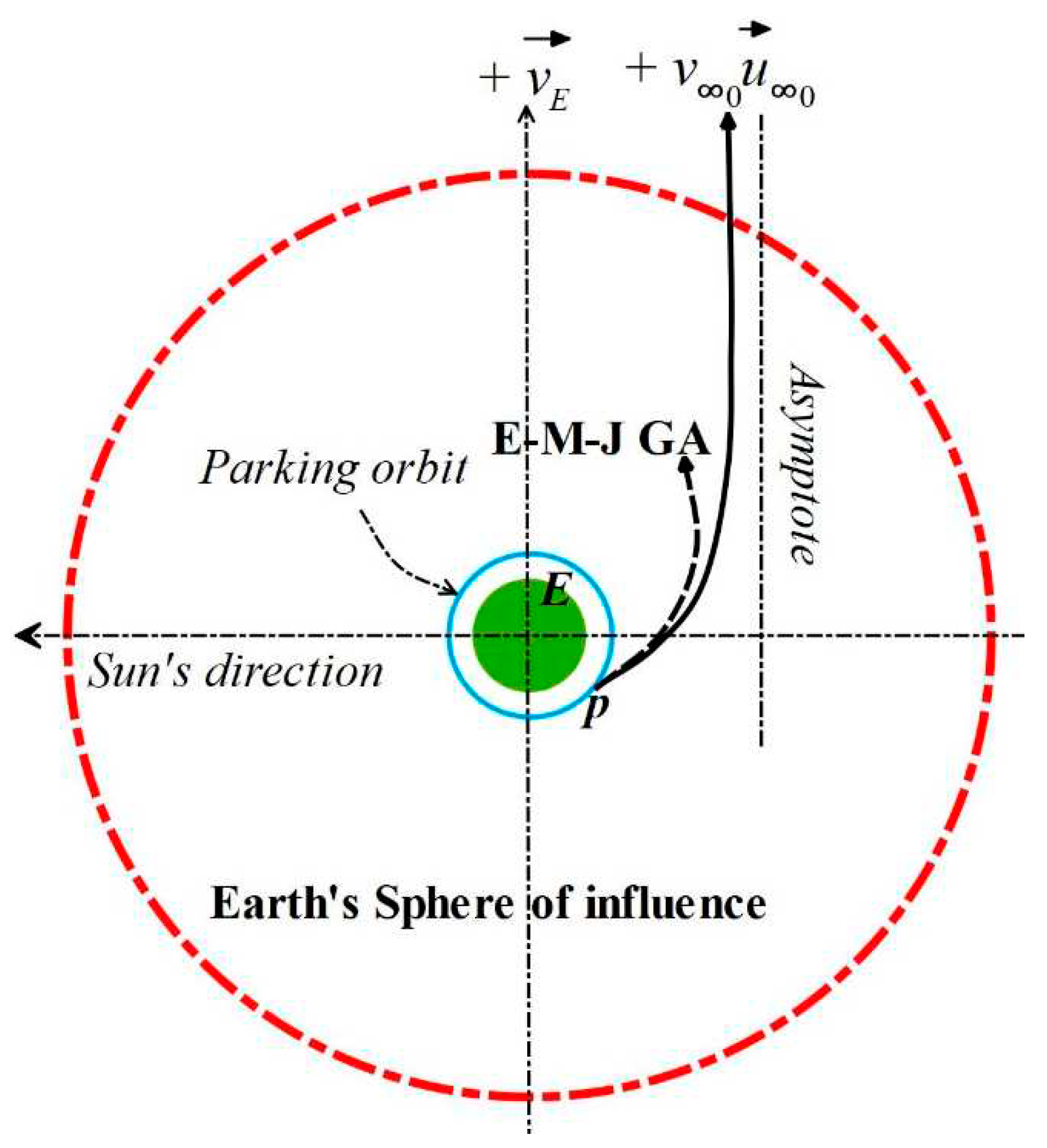
Figure 2.
GA maneuver in a two-body system.
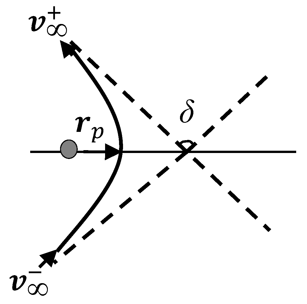
Figure 3.
GA impulsive model.
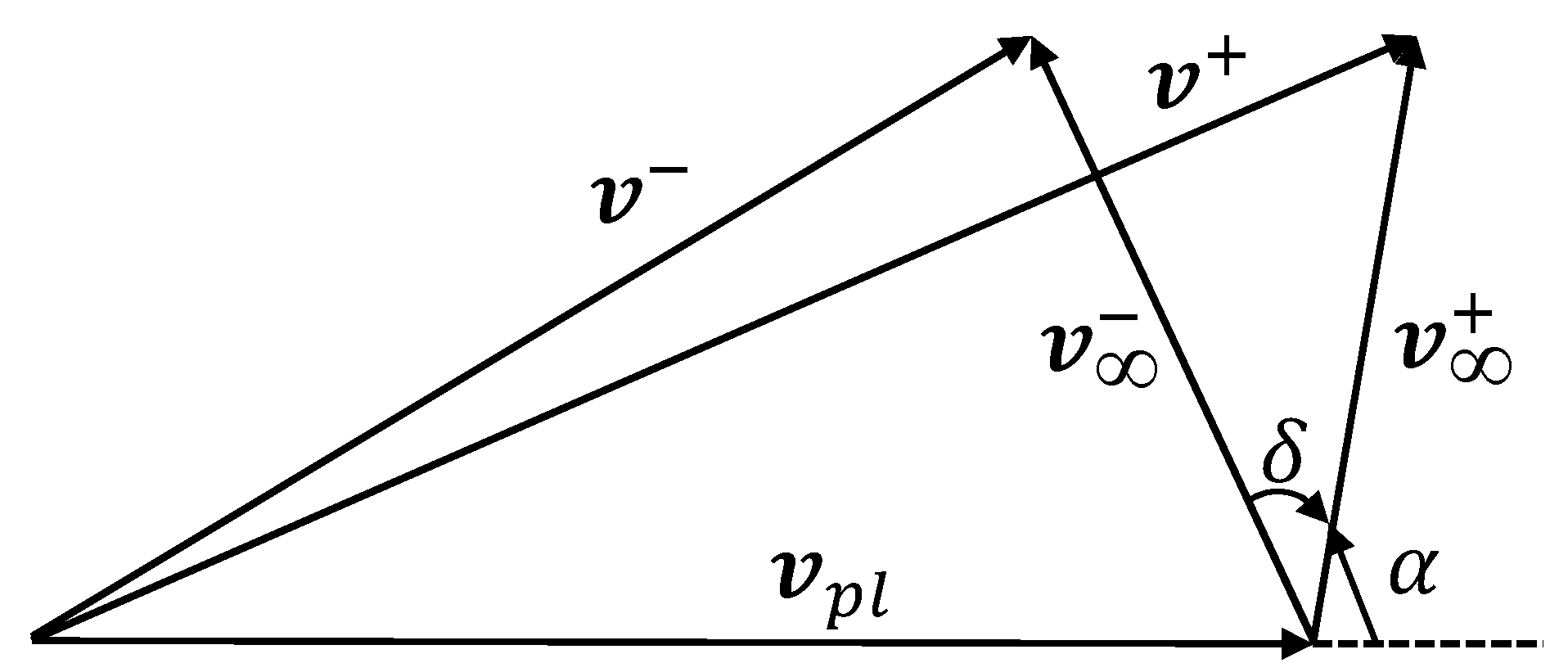
Figure 4.
Computational flowchart of the dual-step optimization algorithm.
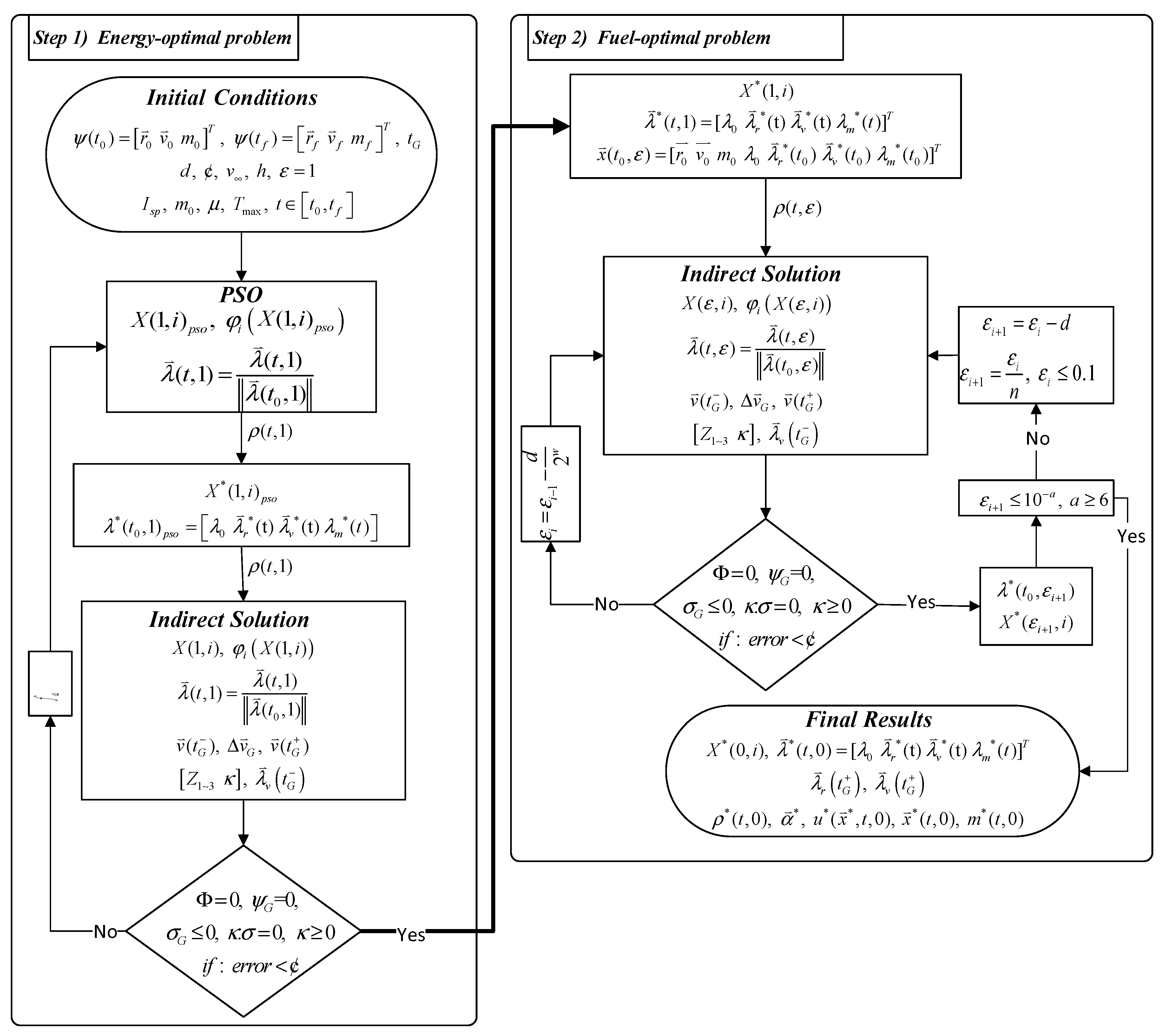
Figure 5.
Initial step of SF detection.
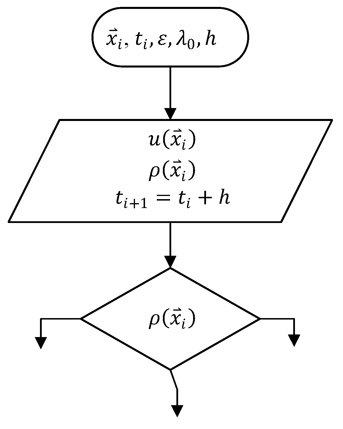
Figure 6.
Flowchart illustrating the SF detection procedure when exceeds .
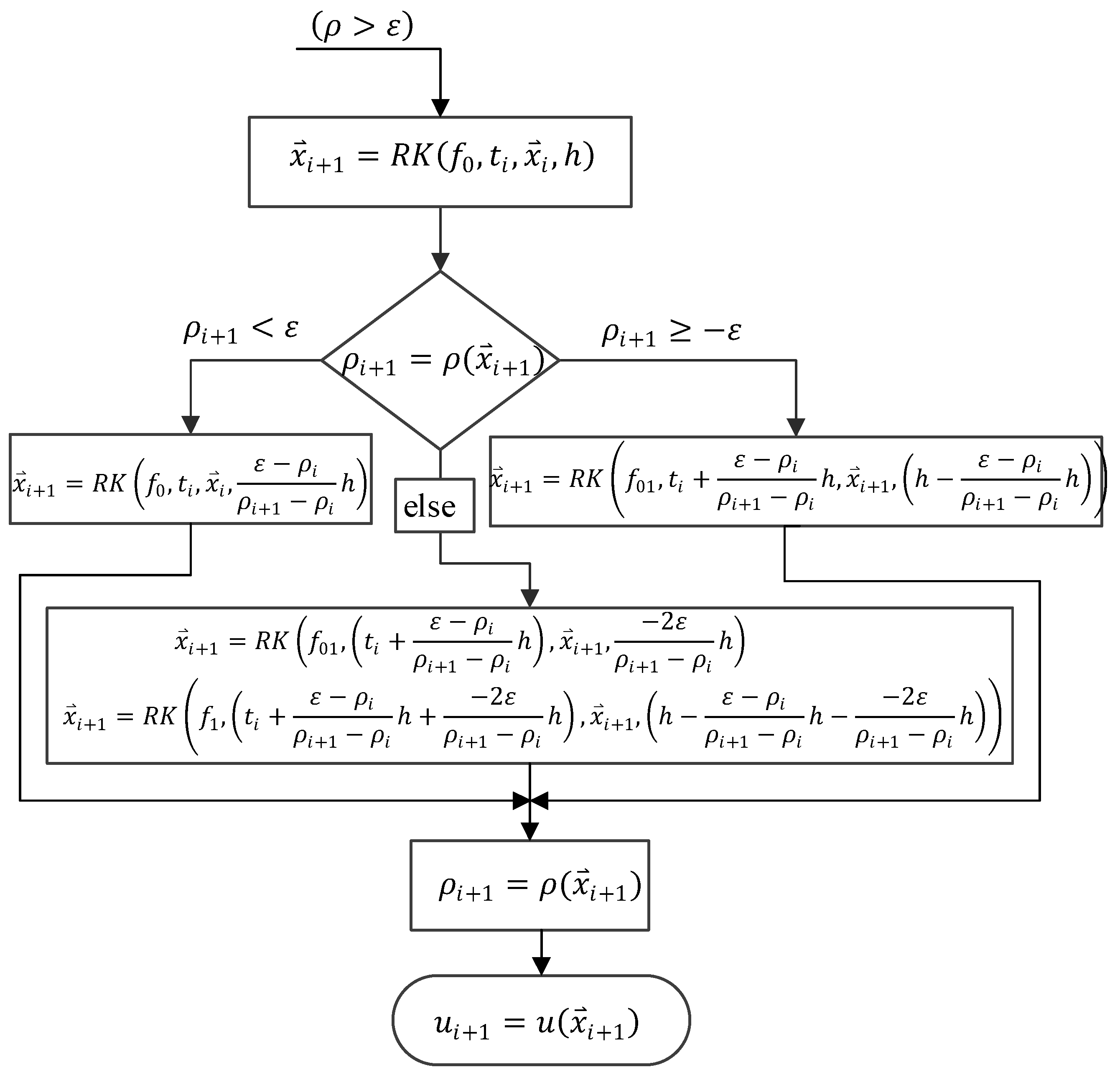
Figure 7.
Flowchart illustrating the SF detection procedure when is less than .
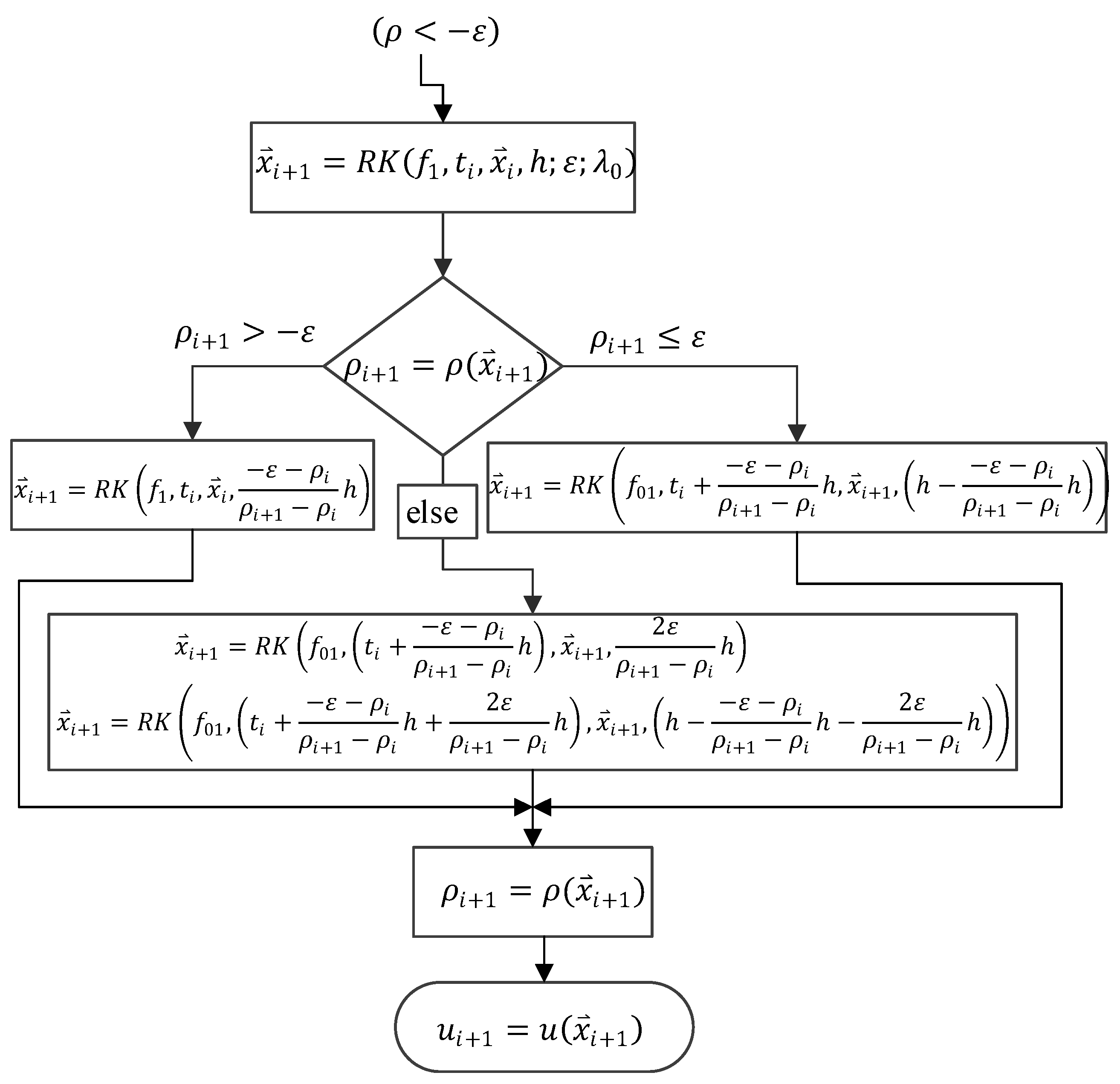
Figure 8.
SF detection procedure for when is within the range .
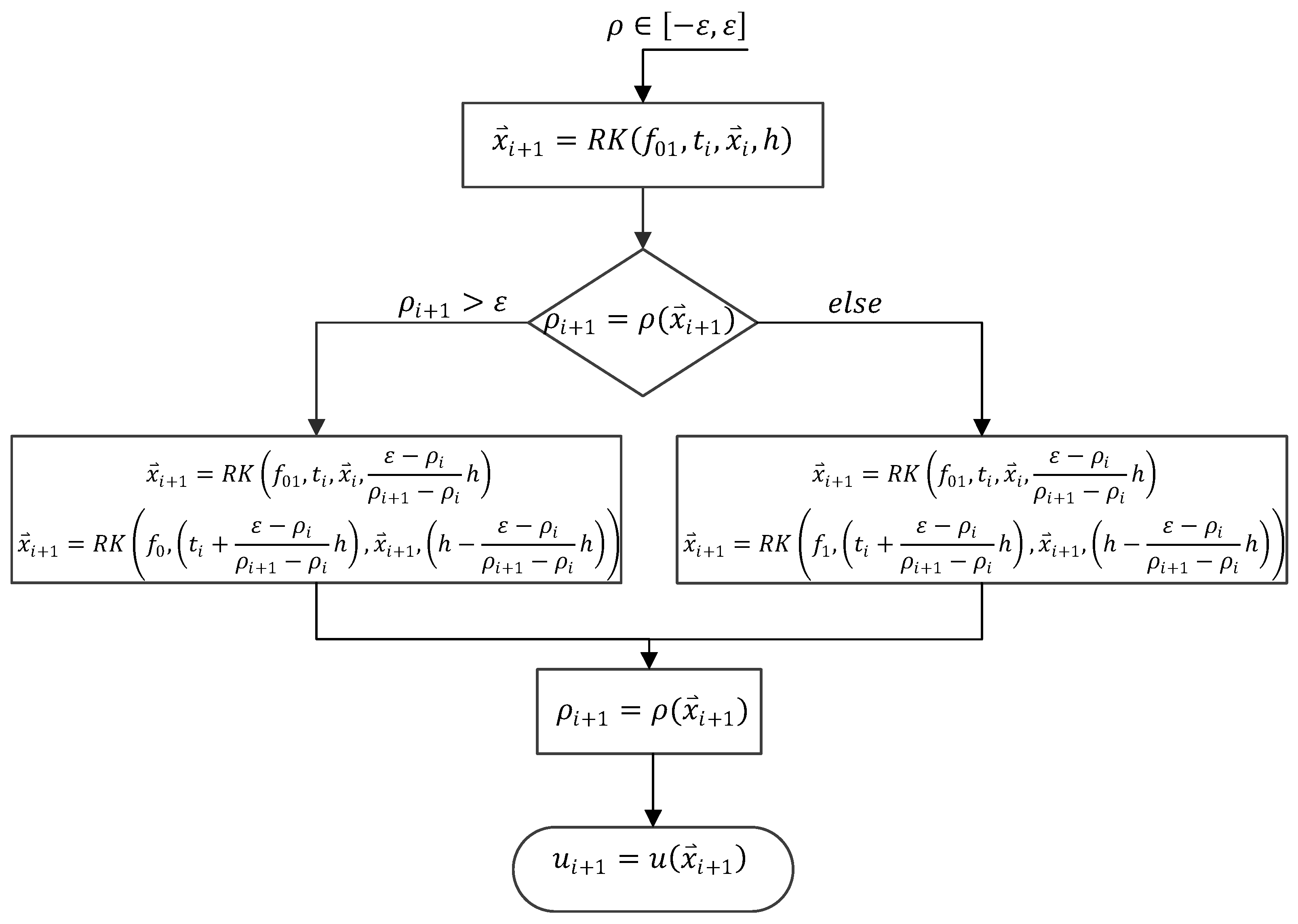
Figure 9.
Earth-Mars-Jupiter energy- and fuel-optimal thrust profiles with switching function detection for bang-bang optimal-control.
Figure 9.
Earth-Mars-Jupiter energy- and fuel-optimal thrust profiles with switching function detection for bang-bang optimal-control.
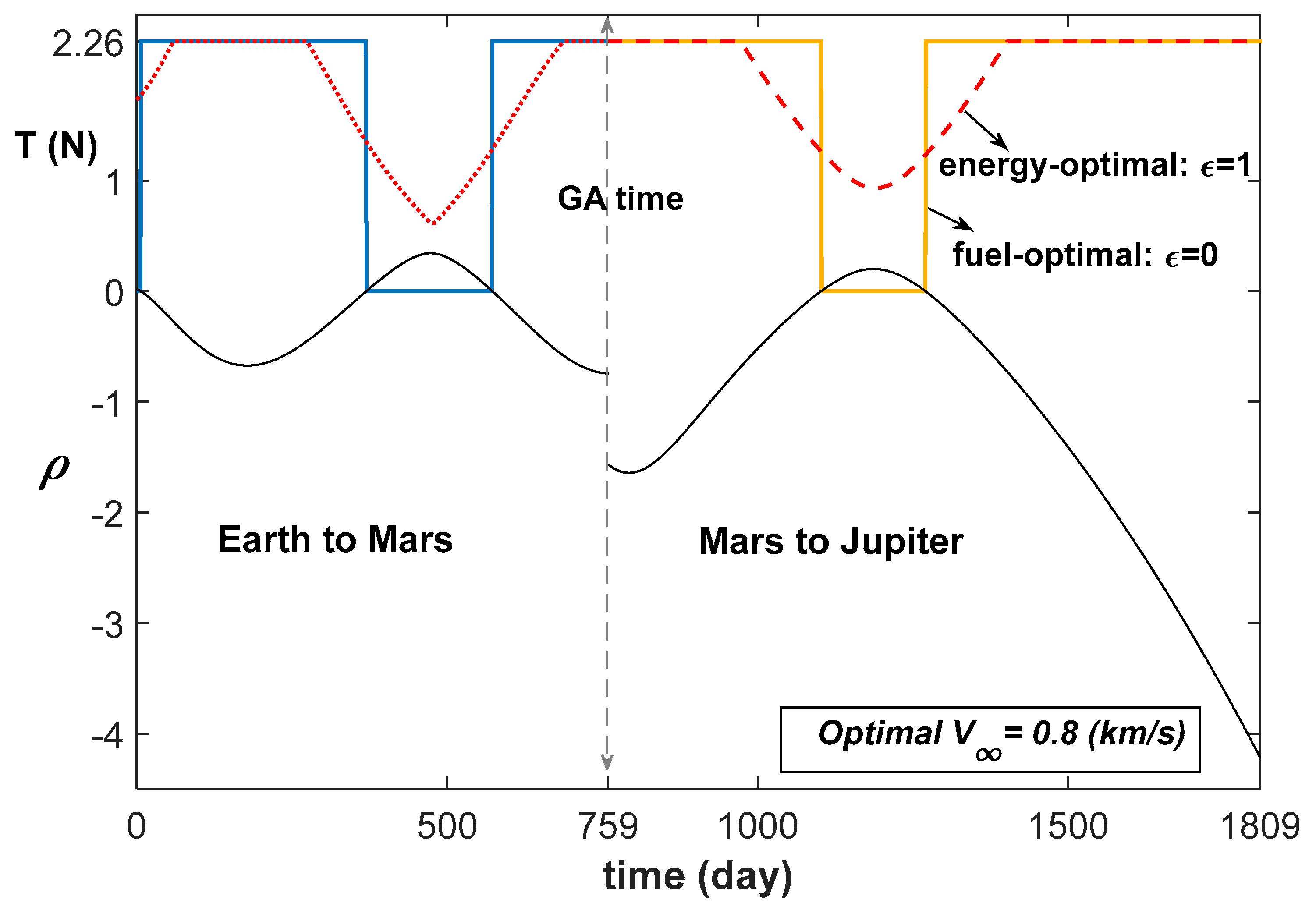
Figure 10.
Earth-Mars-Jupiter GA fuel-optimal low-thrust spacecraft trajectory.
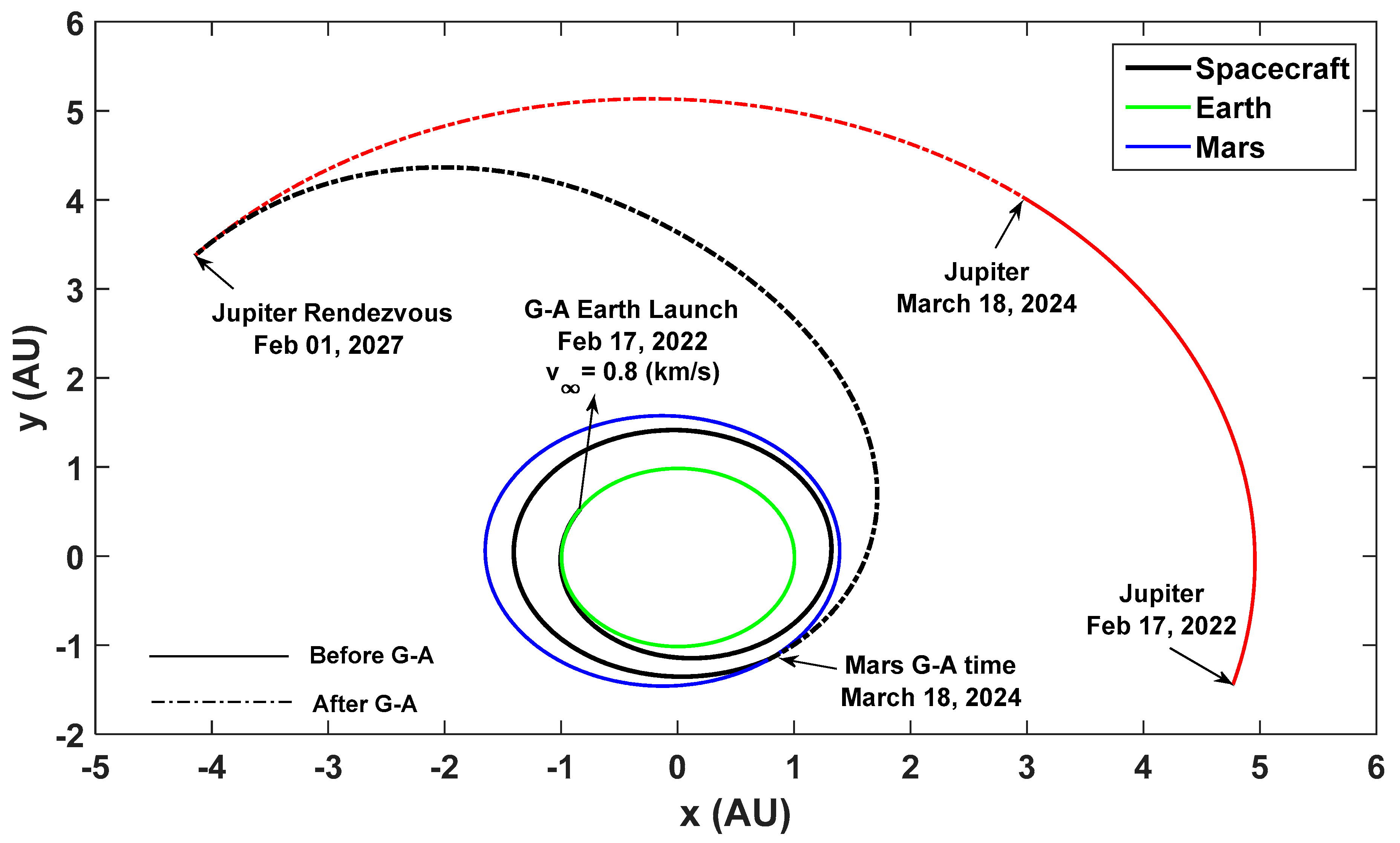
Figure 11.
Fuel-optimal consumption with co-states vectors.
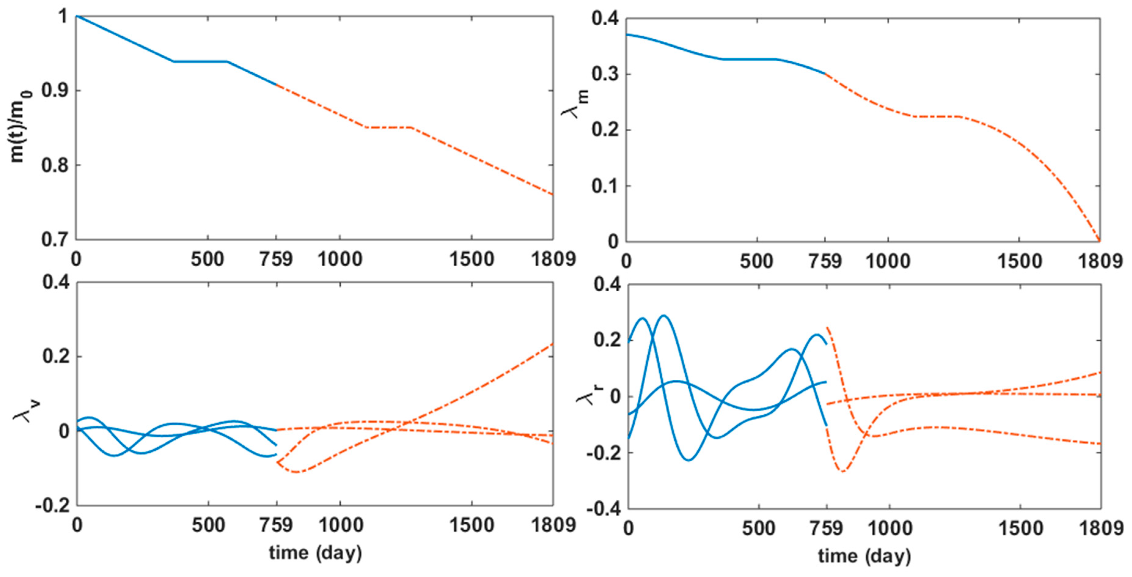
Table 1.
Boundary values and parameters pertinent to the Earth-Mars-Jupiter mission.
| Parameter | Value |
|---|---|
| Initial Position, km | [-1.25326142025922E+08, 7.83493051133693E+07, -3.62097454475238E+03] |
| Initial Velocity, km/s | [-1.62697077142250E+01, -2.53616129608122E+01, 1.47459860098919E-03] |
| Final Position, km | [-6.20180296761522E+08, 5.04570725212524E+08, 1.17797453566354E+07] |
| Final Velocity, km/s | [-8.40428050226635E+00, -9.53464925506379E+00, 2.27651689048206E-01] |
| Initial time, TDB | Feb 17, 2022 |
| Time of Flight, day | 1809 |
| GA time, TDB | March 18, 2024 |
| Final time, TDB | Feb 01, 2027 |
| , kg; ( | 20000 |
| , kg; ( | 19819 |
| , s | 6000 |
| , N | 2.26 |
Table 2.
Optimal co-states for E-M-J mission.
| [0.743699843081560; 0.352463239633363, -0.277598991926813, -0.079343331137383; 0.023718570580293, 0.049511669434066, 0.003327795085571; 0.457631920898898] |
[0.743699843081560; 0.192035090839654, -0.149833850785203, -0.063080789937559; 0.011833279537100, 0.026101523172379, 0.002858568363144; 0.370611693389334] |
Table 3.
The Comparison Results.
| Our results | GALLOP | |
|---|---|---|
| GA time, , TDB | March 18, 2024 | March 18, 2024 |
| TOF, day | 1,809 | 1,809 |
| GA altitude, , km | 500 | 500 |
| , km/s | 0.8 | 1.04 |
| GA , km/s | 3.654 | -- |
| 53.74 | -- | |
| 1.2256e-16 | -- | |
| Final mass, , kg | 15,068.17 | 14,879 |
| GA time, , TDB | March 18, 2024 | March 18, 2024 |
Table 4.
GA Numerical Results of E-M-J Mission.
| Parameter | Value |
|---|---|
| , km | [1.16465658375768E+08, -1.73955158925876E+08, -6.50236091435127E+06] |
| , km/s | [2.10481455623537E+01, 1.55555848401697E+01, -1.90278457157558E-01] |
| GA , AU/yr | [0.524178202715554, -0.565039214276219, 0.008672119576309] |
| GA , AU/yr | [0.765632779887656, 0.088191564273440, -0.011661984497357] |
| GA , AU/yr | [0.241454577172102, 0.653230778549659, -0.020334104073666] |
| GA | [0.008360758766825, -0.062264141998319, 0.078717645223935, -0.053488824816944; 0.030663561324637] |
Disclaimer/Publisher’s Note: The statements, opinions and data contained in all publications are solely those of the individual author(s) and contributor(s) and not of MDPI and/or the editor(s). MDPI and/or the editor(s) disclaim responsibility for any injury to people or property resulting from any ideas, methods, instructions or products referred to in the content. |
© 2024 by the authors. Licensee MDPI, Basel, Switzerland. This article is an open access article distributed under the terms and conditions of the Creative Commons Attribution (CC BY) license (http://creativecommons.org/licenses/by/4.0/).
Copyright: This open access article is published under a Creative Commons CC BY 4.0 license, which permit the free download, distribution, and reuse, provided that the author and preprint are cited in any reuse.
MDPI Initiatives
Important Links
© 2024 MDPI (Basel, Switzerland) unless otherwise stated


