Preprint
Article

Feasibility of THT-Induced Microstructure Gradients and Their Effects on Fatigue Properties in Additively Manufactured Cylindrical and in Conventionally Manufactured Tube-Like Ti-6Al-4V Specimens

Altmetrics

Downloads

116

Views

38

Comments

0

Submitted:

12 January 2024

Posted:

15 January 2024

You are already at the latest version

Alerts
Abstract
Technical components should be produced sustainably and are subject to growing demands in terms of durability and reliability. To meet these expectations, the development of thermochemical processes is auspicious. Titanium alloys, which have a comparatively high gas solubility, allow temporary hydrogen (H) loading, often called thermo hydrogen treatment (THT). THT causes lattice deformation and reduces the β transformation temperature. These effects enable an adjustment of the microstructure, which improves the mechanical properties as compared to those produced conventionally. Furthermore, the process is applicable to complex geometries that cannot be surface hardened by mechanical surface treatment techniques. The investigation presented intends to realize a local microstructure gradient in additively via laser-powder bed fusion (L-PBF) manufactured cylindrical Ti–6Al–4V specimens by changing the distribution and morphology of strengthening precipitates as well as the β grain size depending on the distance to the surface, which should improve the material fatigue properties. To evaluate the mechanical properties of such THT-induced microstructure gradients, the resulting change in fatigue life in the LCF and HCF range was determined by stress-controlled cyclic deformation tests. Besides, the resulting microstructure was characterized by means of XRD and TEM. In addition to the additively manufactured and thermo hydrogen treated cylindrical specimens, conventionally produced tube-like specimens were thermo hydrogen treated and examined. For the THT-induced microstructure gradients, numerically simulated H concentration profiles as well as experimentally determined hardness profiles were used for the evaluation of the THT process. The study shows that H-loading at 500°C and H-degassing at 750°C, followed by aging at 550°C, allows the establishment of a microstructure gradient that shows an 8% improvement in fatigue properties compared to a reference condition without THT. The reason for this improvement is an increased volume fraction secondary alpha phase in the near-surface area of the specimens. Moreover, the results show that the process is applicable a tube-like specimen with varying wall thicknesses.
Keywords: 
Subject: Engineering  -   Metallurgy and Metallurgical Engineering

1. Introduction

Climate change and its consequences create the need for lightweight design and an increase of the durability of components [1,2]. Ti alloys play an important role in this case, since they are an essential material for aviation [3] and are classified according to the β phase stability into the alloy classes α(hex)-, (α+β)- and β(bcc)-Ti alloys [4]. Due to the high gas solubility of the β phase and the complete reversibility of the metal-gas reaction, temporary alloying with atomic H is possible as part of a thermal treatment, the so-called thermos hydrogen treatment (THT) [5]. Senkov and Froes [6] conditiond the possibility of using H as a temporary alloying element to improve the mechanical properties in Ti and its alloys, while Piskovets [7] also tried to use THT on steel. But the investigations revealed a much higher potential for Ti alloys [8]. THT usually consists of the process sequence solution treatment, diffusion-controlled H uptake (hydrogenation), H degassing (dehydrogenation) and aging [9]. The H effects that influence the microstructure can have a positive effect on the mechanical properties of the material. They can be described by two main phenomena: First, H is a strong β stabilizing element in Ti alloys, lowering the β transus temperature Tβ to Tβ(H) and thus reducing grain growth during solution treatment compared to conventional heat treatment (solution treatment and aging) of Ti alloys [10]. Secondly, when the maximum H solubility is exceeded, H causes hydride formation, which is associated with local volume expansion deforming the surrounding lattice plastically [11]. After hydride dissolution, dislocations and vacancies are left, causing an increased nucleation density for precipitation formation during subsequent age hardening [12]. This phenomenon contributes to a more homogeneous and finer α precipitate morphology and, thus, higher hardness. Additionally, the locally increased dislocation density left by the former hydrides stimulates the recrystallization kinetics during subsequent annealing (dehydrogenation), potentially leading to a refined microstructure [13]. Previous studies on THT have demonstrated that this technique can yield to increased strength under cyclic and static loading conditions by generating a homogeneous microstructure with finer characteristics compared to conventionally heat-treated Ti alloys [9,14,15]. THT was also applied to additively via LPBF manufactured specimens, leading to a homogeneous microstructure with improved mechanical properties at quasistatic loading [16,17]. Sun et al. delivered a crucial contribution to the THT design on Ti–6Al–4V by determining the Ti–6Al–4V/H phase diagram experimentally [18] and applying the knowledge to the additively manufactured (AM) specimens [19].
The aim of this investigation is the realization of a microstructure which exhibits a microstructure gradient depending on the surface distance, which improves the properties relevant for the application of cyclically stressed components, particularly the strength of aircraft components subjected to cyclic loading in the HCF (High Cycle Fatigue) and LCF (Low Cycle Fatigue) regimes. Microstructure gradients can be generated by thermomechanical treatment in general [20,21,22] and in Ti alloys [23,24,25,26,27] and thermochemical treatments [28,29,30,31,32], such as THT [33,34]. By employing THT (a process similar to ref. [35]), the goal is to establish a fine, equiaxed microstructure in the near-surface region, leading to a significant extension of the fatigue crack initiation phase. Simultaneously, a coarse, lamellar microstructure is targeted in the core, which decelerates the propagation of occurring long fatigue cracks [15,34]. Previous studies by Berg and Wagner [36] successfully achieved microstructure gradients in metastable β-Ti alloys using thermomechanical treatments to prolong fatigue life.
As described in [15,37], for conventionally manufactured cylindrical Ti–6Al–4V specimens, microstructure gradients in the surface near region, characterized by a fine and globular morphology, have already been succeeded by applying THT even without subsequent aging. The promotion of THT-induced microstructure grading with regard to industrial manufacturing and usage application requires further feasibility studies. Therefore, in this study the THT-process had been transferred to additively manufactured cylindrical specimens and to conventionally manufactured tube-like specimens. The interrelation with the resulting mechanical properties was determined.

2. Materials and Methods

The study was carried out by using the (α+β)-Ti alloy Ti–6Al–4V as it is described in [15] (α lamella width: 10-80 µm, averaged 30 µm; α colony width: 600-800 µ). This alloy is widely used e.g. in aviation [38,39]. Compared to β-Ti alloys, which boast more potential due to their higher H solubility [40], the (α+β)-Ti alloy is more suitable for the generation of a microstructure gradients [34]. Hollow structures, such as precision tubes, can be regarded as promising usage applications. For this purpose, a tube-like specimens (length L = 80 mm) with variable wall thickness (Øouter = 10 mm, Øinner_1 =8 mm , Øinner_2 =6 mm, thickness transition at half of the length) were machined from the forged bar representing the shape of a precision tube. Figure 1 a) illustrates the applied time-temperature regime of the THT+aging process, which starts with a solution treatment.
On the other hand, the material Ti-6Al-4V has long been established in additive manufacturing (AM). Thus, cylindrical specimens intended for THT have been additively manufactured via laser-powder bed fusion (L-PBF). Latter was carried out by Liebherr-Aerospace Lindenberg GmbH, Germany. Suitable time and temperature parameters for the THT process to generate microstructure gradients are taken from previous work [37]. The initial microstructure was lamellar characterized by a α lamella width of 2.3±0.8 µm. Hydrogenation and dehydrogenation experiments were carried out in a horizontal annealing apparatus (for specimen preparation see [15]) under supply of a He/H2 gas mixture with 10 % H2 (hydrogenation) or in vacuum (p = 2x10⁻⁵ mbar, dehydrogenation) on all specimens. The H concentration after the hydrogenation experiments were validated with hot gas melt extraction (Leco Corporation, St. Jospeh, MI, USA) and the selection of the aging parameters (550°C, 6 h) was based on the results of Paramore et al. [41]. Figure 1 b) summarizes the time-temperature regime of the THT+aging process applied to the AM specimens. Since a lamellar microstructure was already present after AM, solution treatment as initial process step was not necessary. To evaluate the resulting mechanical properties tensile, rotating bending and fatigue test were carried out.
The reference condition of the demonstrator (Figure 1 a): reference) represents demonstrator specimens that were produced by THT [37] as well as after the reference heat treatment in order to compare the resulting microstructural changes and hardness profiles. Due to the complex specimen geometry, the evaluation of the mechanical technological properties is limited to hardness measurements.
For the AM specimens the reference (Figure 1 b): Reference (AM) represents the condition generated after the L-PBF process by Liebherr and was compared to specimens that passed through the THT without (THT (AM)) and with aging (THT+aging (AM)). The resulting cH profiles, the hydrogenation and dehydrogenation times as well as the surface correction factors were calculated according to the method described in [35] by using finite-element method (FEM) and Matlab® (R2020, developed by The MathWorks, Natick, MA, USA) as well as COMSOL Multiphysics® (develop by Comsol Multiphysics GmbH from Göttingen, Germany) The mechanical properties of the (aged) THT and the reference condition under quasi-static, uniaxial load were evaluated by means of a tensile test according to DIN EN ISO 6892-1 on a spindle-driven universal testing machine from Zwick GmbH & Co KG with a maximum test load of 200 kN (specimen geometry: DIN 50125 - B6 x 30). The corresponding fatigue behavior was investigated by fatigue tests in accordance with DIN 50100:2016-12. For this purpose, a resonance testing machine of the type “Testronic” from RUMUL AG (Neuhausen am Rheinfall, Switzerland) was used. The rotating bending tests were carried out at a rotating bending apparatus from Carl Schenck AG (Darmstadt, Germany, type: PUNN). The specimen geometry used boasts a specimen test diameter of 5.885 mm (rotating bending, test length: 20 mm) and 6 mm (cyclic deformation, test length: 12 mm). The specimens were tested at R=–1 and f=100 Hz after mechanical surface polishing. In addition, the stereological parameters were determined by SEM-BSE images of cross sections using a dual-beam system from FEI (type Helios Nano-Lab 600) and the image processing software Lince 2.4.2 ß (developed by TU Darmstadt, Darmstadt, Germany and ImageJ 1.52a, developed by National Institutes of Health, Bethesda, MD, USA). Furthermore, local Vickers hardness profiles were determined applying hardness testing at 2 kp for 10 s. TEM investigations were conducted with the Talos™ F200X scanning transmission electron microscope (S/TEM) from FEI (Hillsboro, OR, U.S.A.) at an accelerating voltage of 200 kV using a 4k x 4k Ceta™ 16M camera (FEG) and a SuperX detector to detect the microstructural effects, that were not visible at SEM.

3. Results and Discussion (former Results)

3.1. Tube-like specimen

3.1.1. Calculated H concentration profiles

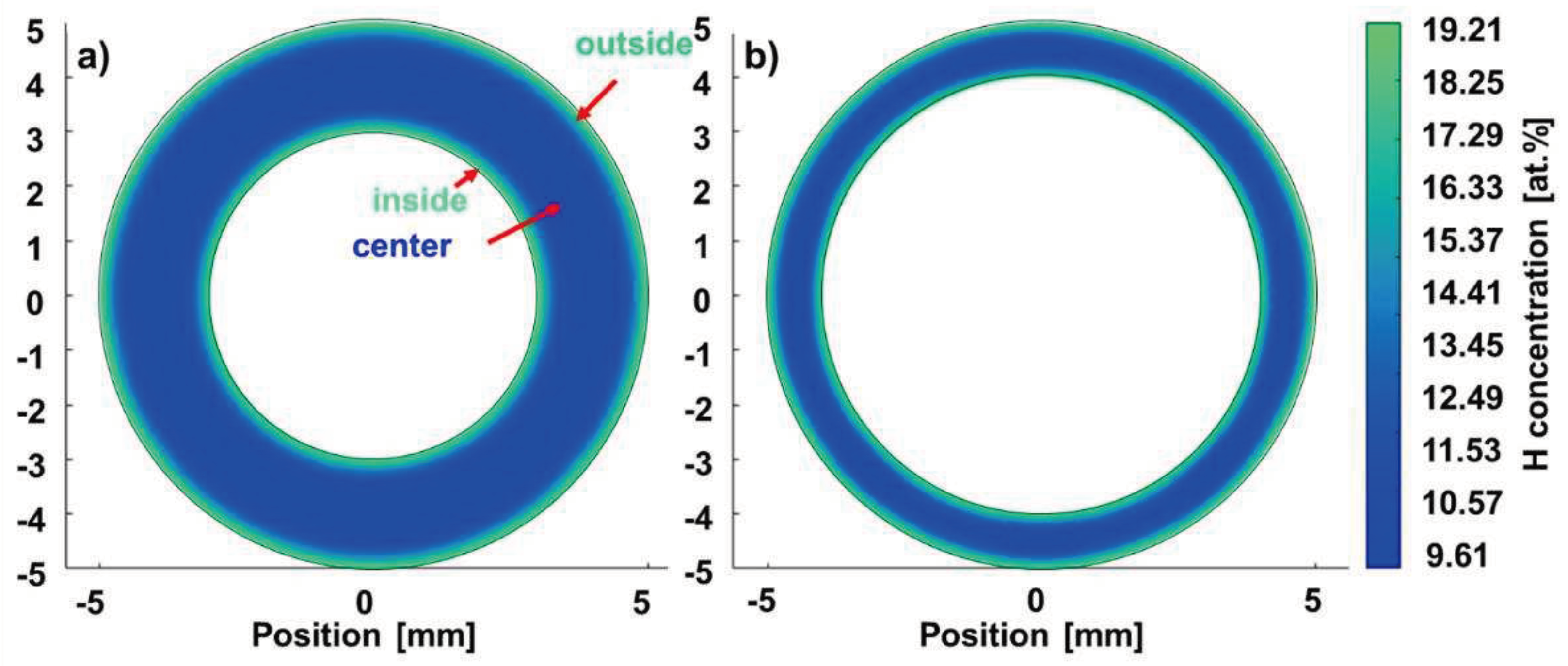
Figure 2 shows the H concentration profile in the tube-like specimen simulated by means of FEM in 2-dimensional space after hydrogenation for both pipe cross-sections.
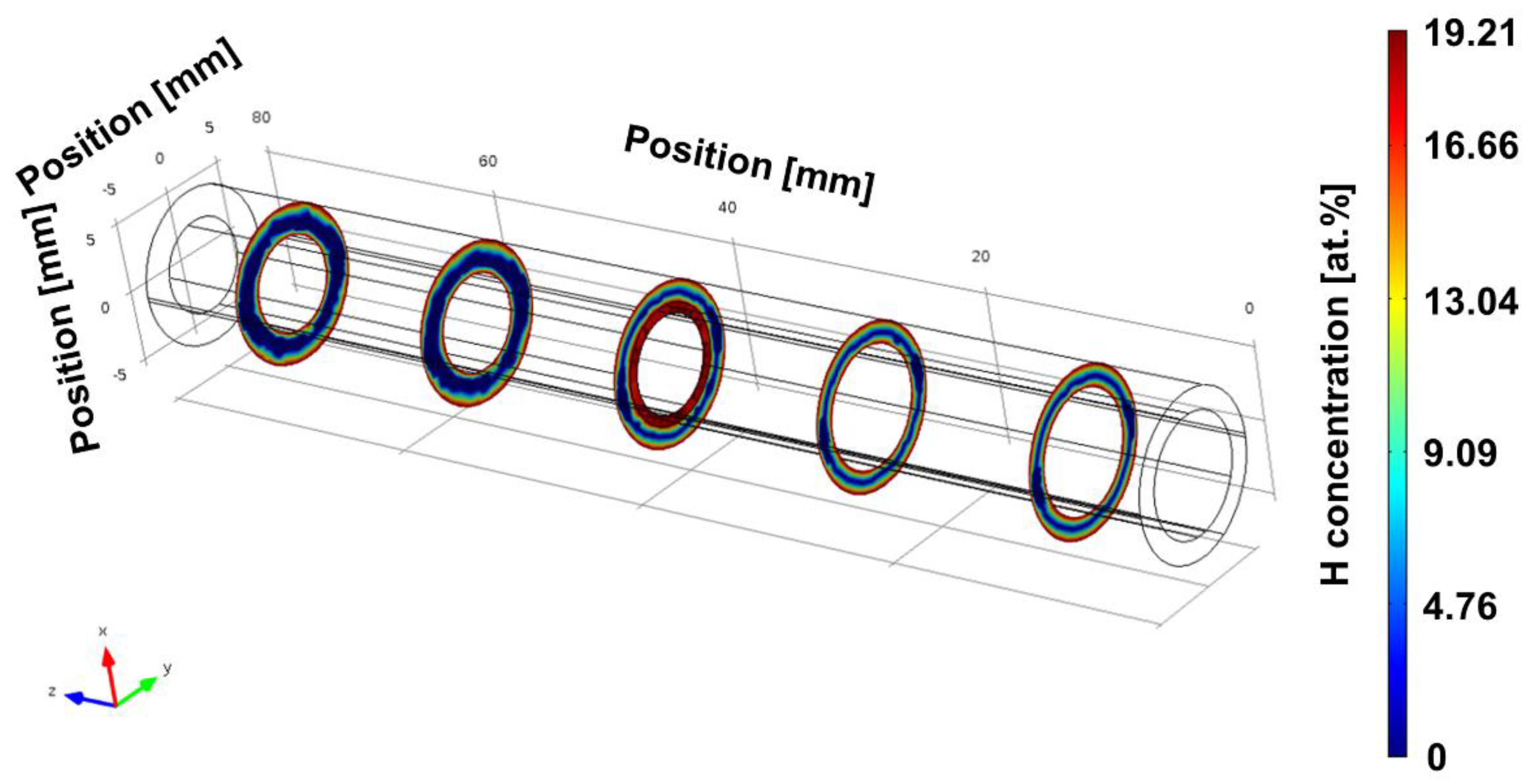
After hydrogenation, the inner part of the specimen (marked as "center" in Figure 2 b) is half as loaded with H as the near surface areas (areas marked as "inner" and "outer" in Figure 2 a)) for both cross-sections (Figure 2 a) and b)). The H concentration of 15 at.% required for the formation of hydrides acc. to. ref [42] is reached in a range up to ~500 µm. Figure 3 shows the H concentration profile of the demonstrator component simulated by FEM in 3-dimensional space by COMSOL Multiphysics® after hydrogenation.
The H concentration profile for the thick pipe wall thickness determined using COMSOL Multiphysics® (Figure 3) corresponds approximately to the estimate made using Matlab®. According to the calculation with COMSOL Multiphysics®, the end with the thin wall thickness is loaded almost over the entire cross-section. Accordingly, the results of the simulation in 3 D (COMSOL Multiphysics®) for the thin-walled tube cross-section deviate from the results simulated in 2 D (Matlab®). This observation can be explained by the fact that COMSOL Multiphysics®, in contrast to Matlab®, can take diffusion along the pipe axis into account. Table 1 summarizes the hydrogenation and dehydrogenation parameters used, which were designed based on the results of the previous hydrogenation and dehydrogenation tests [15]. The table contains the hydrogenation (tH) and dehydrogenation durations (tD) plus the surface correction factors after hydrogenation (SCFH) and dehydrogenation (SCFD), that are defined in ref. [15].
The SCF determined during hydrogenation and dehydrogenation (Table 1) corresponds to the order of magnitude of the SCFH determined for miniature specimens used for in situ fatigue tests in ref. [37]. Accordingly, the dehydrogenation duration of the demonstrator (Table 1) could be designed on the basis of the results of the dehydrogenation tests on the Ø 5 mm specimens from ref. [37].

3.1.2. Experimental determination of hardness profiles

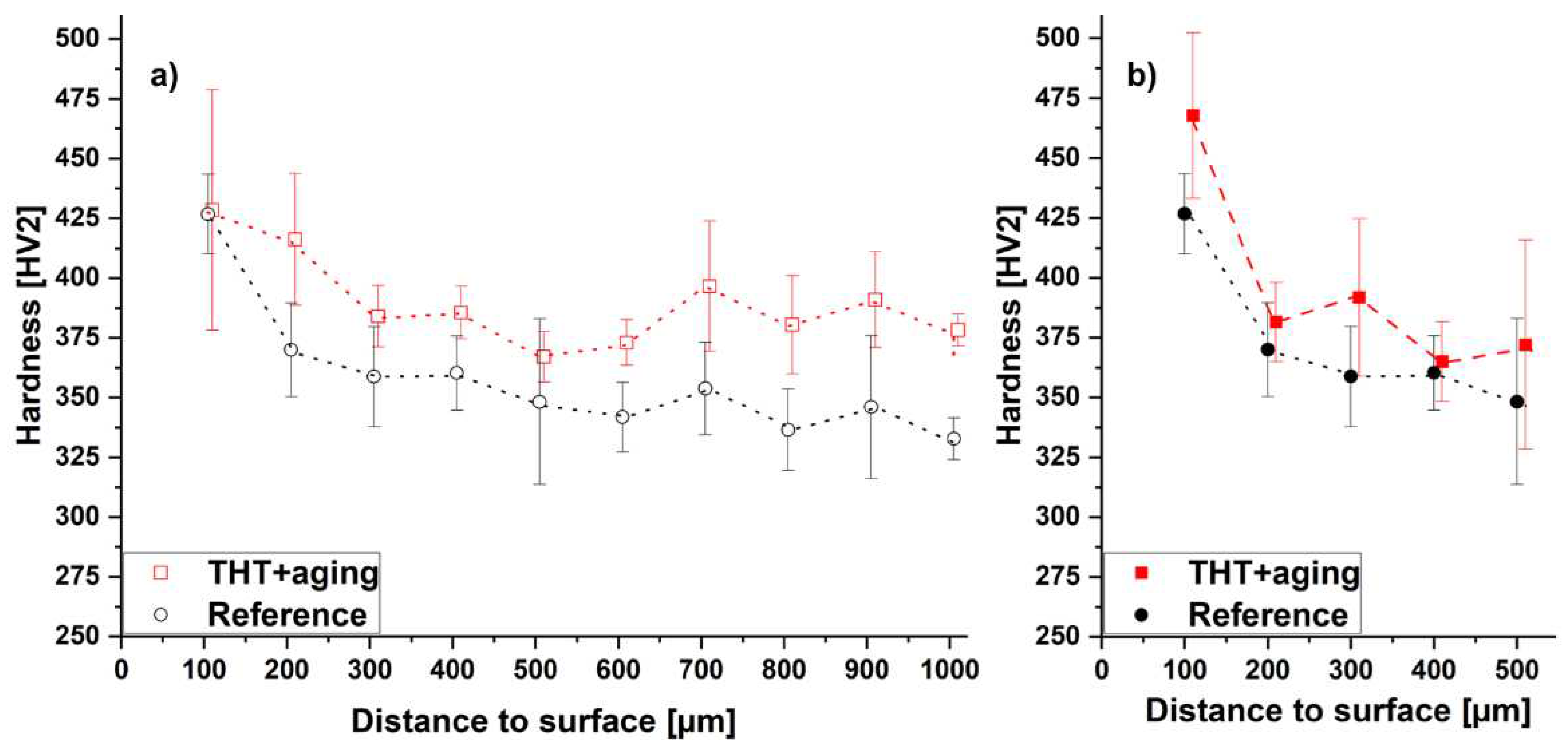
The evaluation of the transfer of the THT-induced microstructure grading is carried out based on experimentally determined hardness profiles and the determination of the stereological microstructure parameters on BSE micrographs. The performance of fatigue tests on tube specimens was not considered to be expedient, since a specimen geometry with a stepped wall thickness does not permit reliable testing. First, Figure 4 shows the experimentally determined hardness curves of the conventionally manufactured tube-like specimens with different wall thicknesses in comparison.
The results of the hardness measurements document a tendency for the hardness to decrease with increasing distance from the surface for the reference and the THT+aging condition at both specimen ends (Figure 4). The THT+aging condition of the specimen’s end with 2 mm wall thickness has an 0.5 – 12 % higher hardness value in all measuring points near the surface. At the specimen’s end with 1 mm wall thickness, the THT+aging condition shows a higher hardness value than the reference in 8 of 10 measuring points and is 1 – 9 % higher than the hardness values of the latter. The THT-induced hardness increase effect is thus greater for the specimen end with 2 mm wall thickness than for the specimen end with 1 mm wall thickness. The results nevertheless suggest that THT including aging (THT+aging) reinforces a hardness gradient induced after solution heat treatment compared to the reference condition. The hardness curves shown here are in the same order of magnitude as the hardness curves determined on fatigue specimens investigated in previous work [37]. The result of the hardness measurements suggests that the THT+aging condition has a greater resistance to crack propagation and, thus, a higher fatigue strength.

3.3.1. Stereological parameters

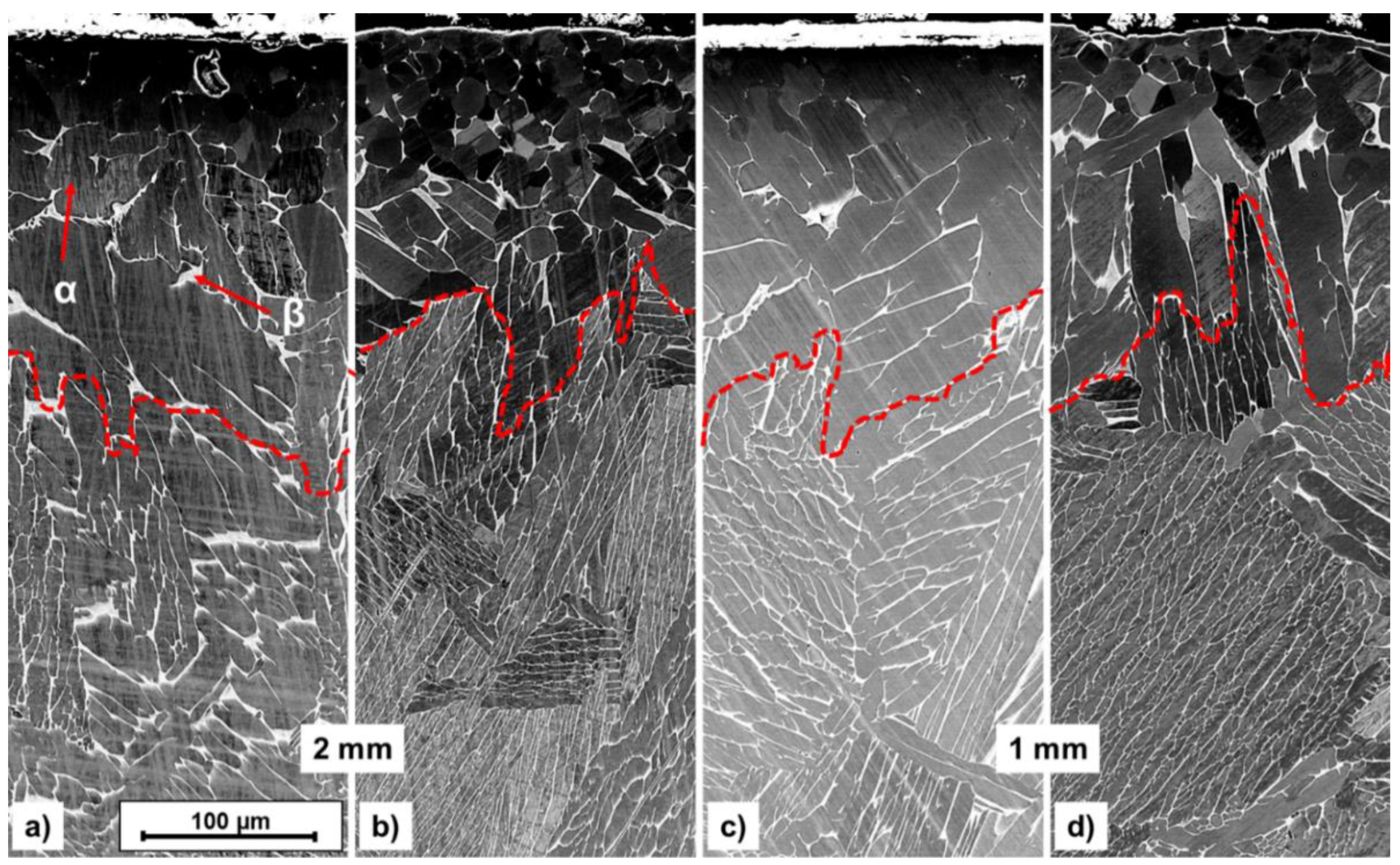
A justification for the THT-induced hardness increase can be provided by the microstructural images shown in Figure 5.
The microstructures of the reference condition (Figure 5 a) and c)) and the aged THT condition (Figure 5 b) and d)) each represent a two-phase (α+β)-structure. The microstructure of both conditions provides regions of globular morphology near the surface that were also observed after solution treatment. With increasing distance from the surface the morphology becomes increasingly lamellar (compare [15]). The stereological parameters that can be determined from Figure 5 are summarized in Table 2.
According to Table 2, the averaged α lamella width (5 µm near the surface and 8–9 µm inside the specimen) and the α colony width (82-141 µm near the surface and 161–302 µm inside the specimen) in THT+aging condition decreases with decreasing distance from the surface. The α lamellae width (near surface: 5–10 µm, center: 8–9 µm) of the reference condition is almost identical near surface and center, while the α colony width is reduced by 24 % (2 mm wall thickness) or increased by 17 % (1 mm wall thickness) in the center and increased by 19 % (2 mm wall thickness) and reduced by 6 % (1 mm wall thickness) near surface. This may account for the observations from the hardness measurements (Figure 4) that THT has a greater effect on the specimen’s end at 2 mm: THT reduces the α lamella (colony) width at the 2 mm specimen end, while the α lamella (colony) width at the 1 mm specimen end does not experience a clear THT-induced decrease.

3.2. AM cylindrical specimens

3.2.1. Calculated H concentration profiles

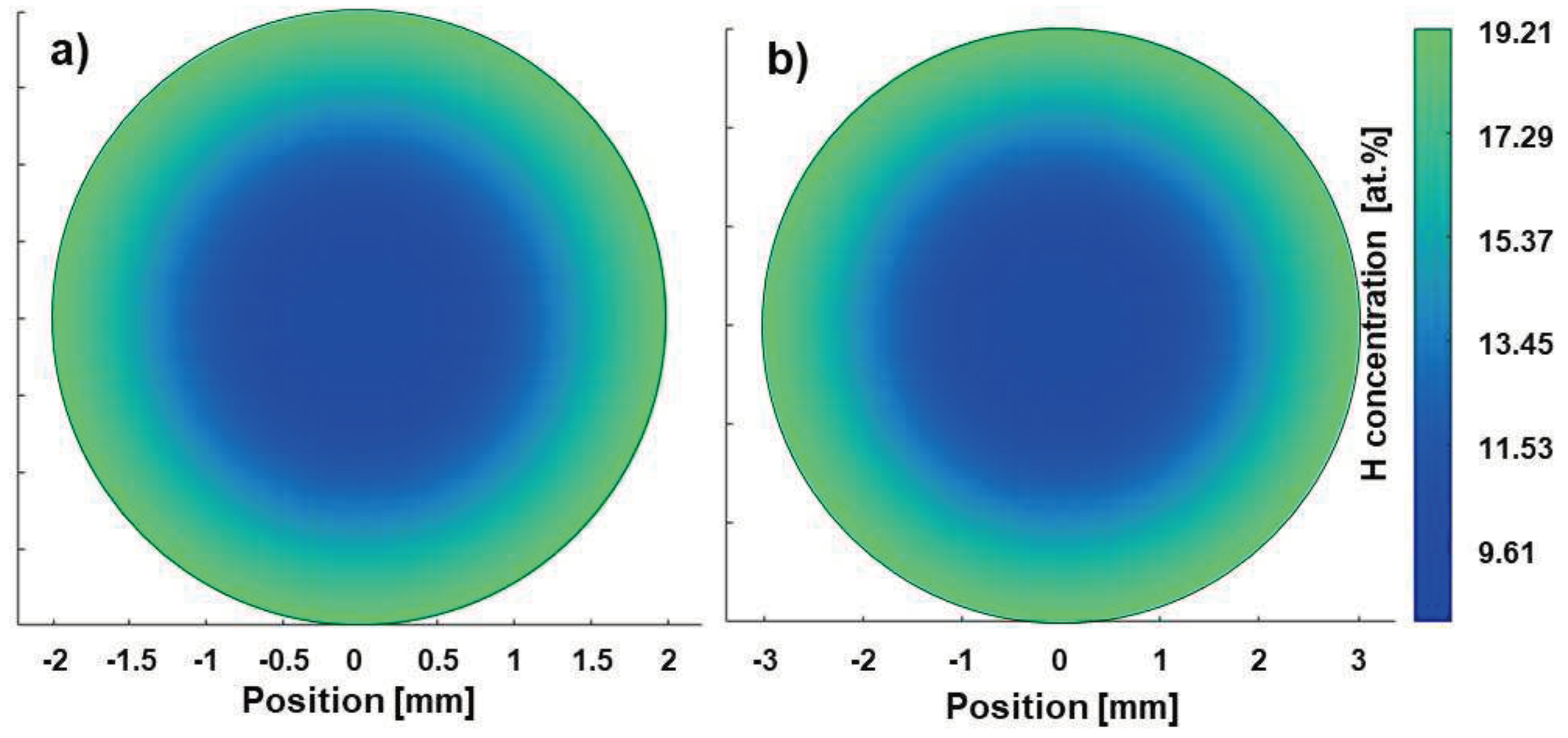
The FEM-estimated H concentration profiles after hydrogenation of the AM specimen geometries, used to evaluate the mechanical properties, are illustrated in Figure 6.
According to the H concentration profiles estimated by means of FEM, the local H concentrations of the near surface region of the fatigue specimens (Figure 6 a)) and the rotating bending as well as tensile specimens according to THT (Figure 6 b)) show a value of cH = 19.21 at.% and a penetration depth of approx. 750 µm (Figure 6 a)) and 900 µm (Figure 6 b)). The center reaches half of the H concentration at the area near the surface for both geometries. The hydrogenation profiles are almost identical and comparable to the conventional specimens investigated in previous work [37]. This leads to the conclusion that the robustness of the THT process is high enough to be transferred to other geometries and other batches. The parameters of the H concentration profiles after hydrogenation, shown in Figure 6, are summarized in Table 3 and differ for both sample geometries since the varying specimen volumes require different hydrogenation and dehydrogenation durations to reach a comparable penetration depth.
The averaged H concentration of the fatigue specimen (line 2 in Table 3) is slightly lower than that of the rotating bending and tensile specimen (line 3 in Table 3). The averaged H concentration after dehydrogenation correspond to values of less than 0.2 at.%, which means that the specimens are considered completely degassed according to ref. [9] and have a H content that corresponds to conventional delivery condition. The SCFH’s of the hydrogenation are almost identical for the two specimen geometries. For the dehydrogenation, they are in the order of magnitude of the two SCFD's of the hydrogenation. The surface of the AM specimens seems to affect the H release more than the conventionally manufactured specimens. A possible explanation may be the lower surface roughness. The conventional specimens, unlike the AM specimens, have small surface depressions (Ø 20 µm, depth: 5 µm) in the initial condition before hydrogenation, which could act as H traps. In a hydrogen-containing atmosphere, this could create local H reservoirs on the specimen surface and slow down the kinetics of H release compared to a plainer surface.

3.2.2. Experimental determination of hardness profiles

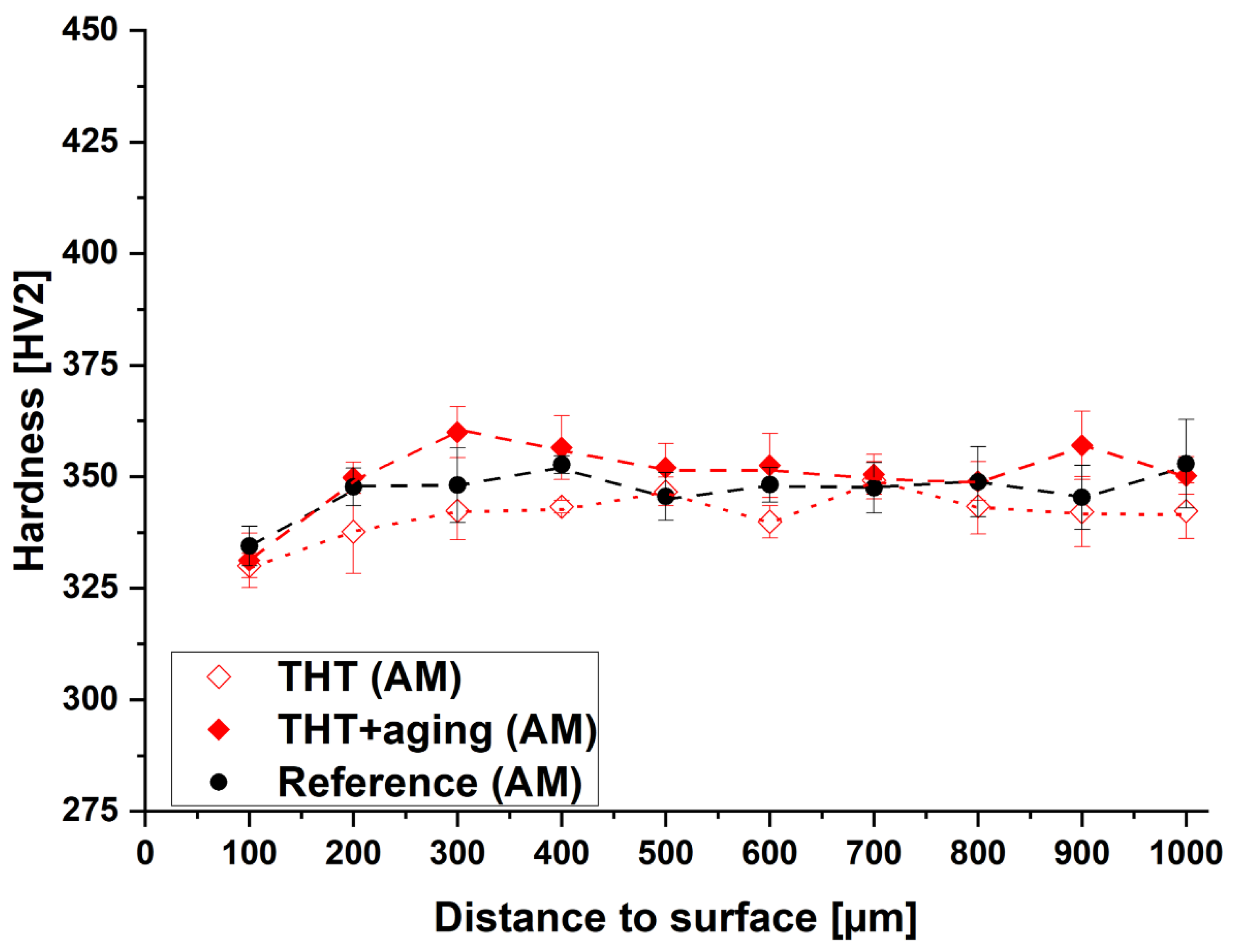
Further evaluation of the THT-induced microstructure gradient is shown in Figure 7 by means of a display of the hardness profiles.
Figure 7 shows that the hardness is constant over the distance to the surface. However, the lowest hardness is recorded near the surface for the reference and the THT conditions. This observation does not correspond to the desired hardness curve, which should indicate a gradient. Since the courses of the three conditions are almost parallel to each other, the initial condition already shows an opposite hardness gradient (lower hardness near the surface than in the center). THT treatment without aging therefore has no influence on reference condition, while aging following THT increases the hardness overall. In comparison to the hardness curves of conventionally manufactured specimen acc. to ref. [37], it is noticeable that the hardness values near the surface for the three conditions examined in this study, comprising 2 – 24 % in the range up to 200 µm distance from the surface, are below the hardness values of the conventionally manufactured specimens. Here, the reference condition shows 2 – 16 % lower hardness values at the identical measuring point (same distance to the surface) over the entire measuring length, while the THT condition shows almost identical hardness values from a surface distance of 500 µm and more. With increasing distance to the surface (from 300 µm), the hardness values of the AM specimens in THT+aging condition are 6 – 12 % higher than those of the conventionally manufactured specimens in THT+aging condition [37]. This increase can be attributed to the smaller α lamella width. Furthermore, the local hardness is hardly influenced by THT and appears to be mainly determined by the initial hardness or the initial α lamellae width. Nevertheless, the microstructure gradient, that is displayed in Table 4, does not result in a hardness gradient.

3.2.3. Stereological parameters

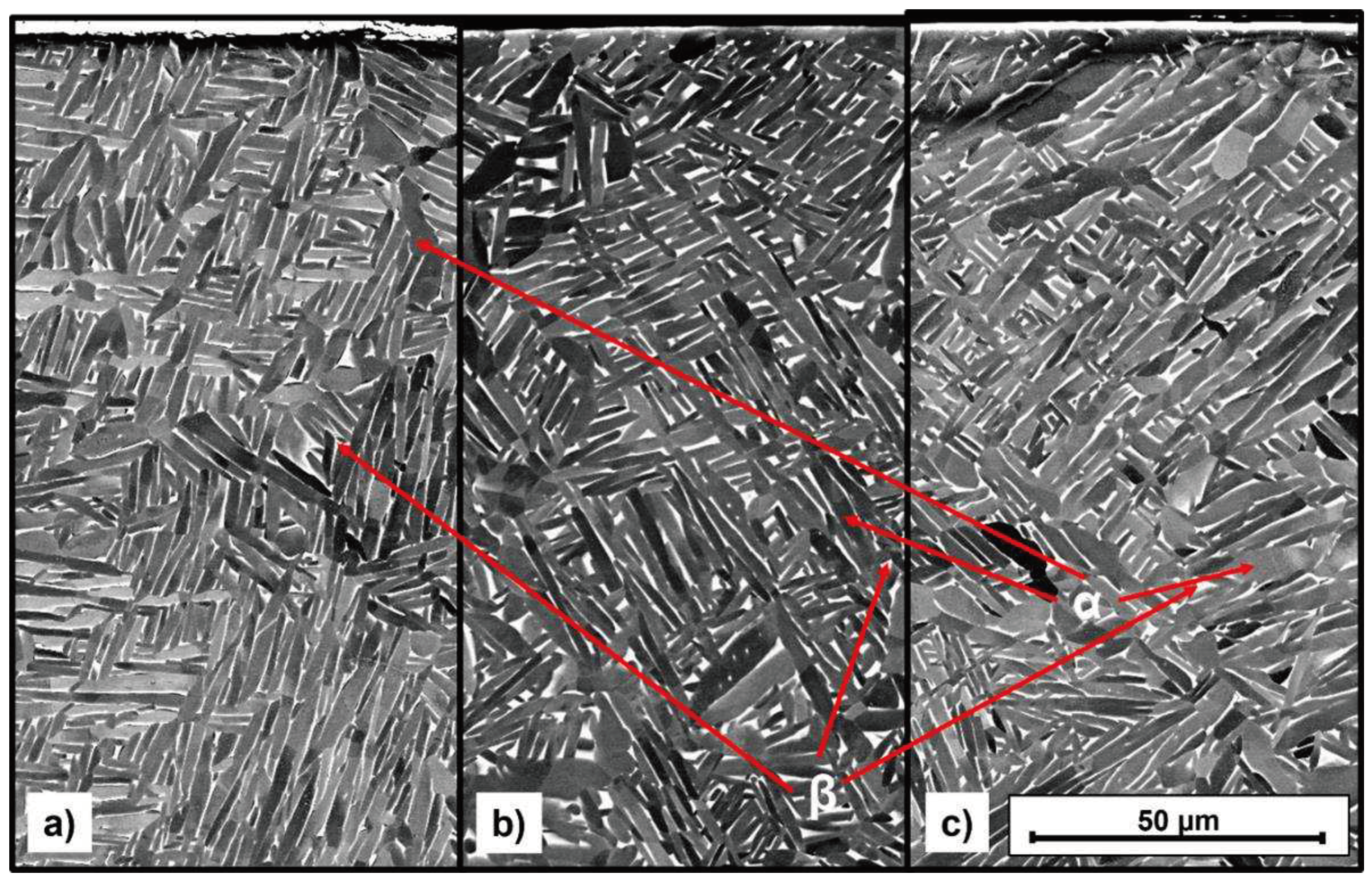
Figure 8 a) to c) shows the microstructures of the reference and the THT+aging condition of the AM fatigue specimens.
The microstructures of the reference condition (Figure 8 a)) and the THT conditions without (Figure 8 b)) and with aging (Figure 8 c)) of the AM specimens represent, like the microstructures of the demonstrator specimens (Figure 5), a two-phase (α+β)-structure with lamellar precipitation morphology. However, the α lamellae are not arranged in colonies but statistically distributed. Table 4 summarizes the quantitative results of the microstructural investigations on the fatigue specimens.
According to Table 4, the β phase fraction increases from the surface to the interior of the specimen both after the condition THT and the condition THT+aging. THT without aging appears to increase the β phase fraction compared to the reference, with subsequent aging reducing this increase (from 3.6 % - 5 % to 1.7 % - 2.9 %). Compared to the reference condition the α lamella width near the surface is reduced by THT by over 20 % and THT+aging by as much as 35 %, while the α lamella width in the center is not changed (without aging) or only slightly changed (<10 % after aging). Compared to the conventionally manufactured tube-like specimens (Table 2), the α lamella width of all conditions is 20 times smaller. This difference is due to the fact that the initial condition of the AM specimens has already been subjected to a process to optimize the fatigue properties, which focuses on reducing the α lamella width. The solution heat treatment of the conventional produced specimens, on the other hand, was carried out to produce clearly distinguishable morphologies as initial condition.

3.2.4. Tensile tests

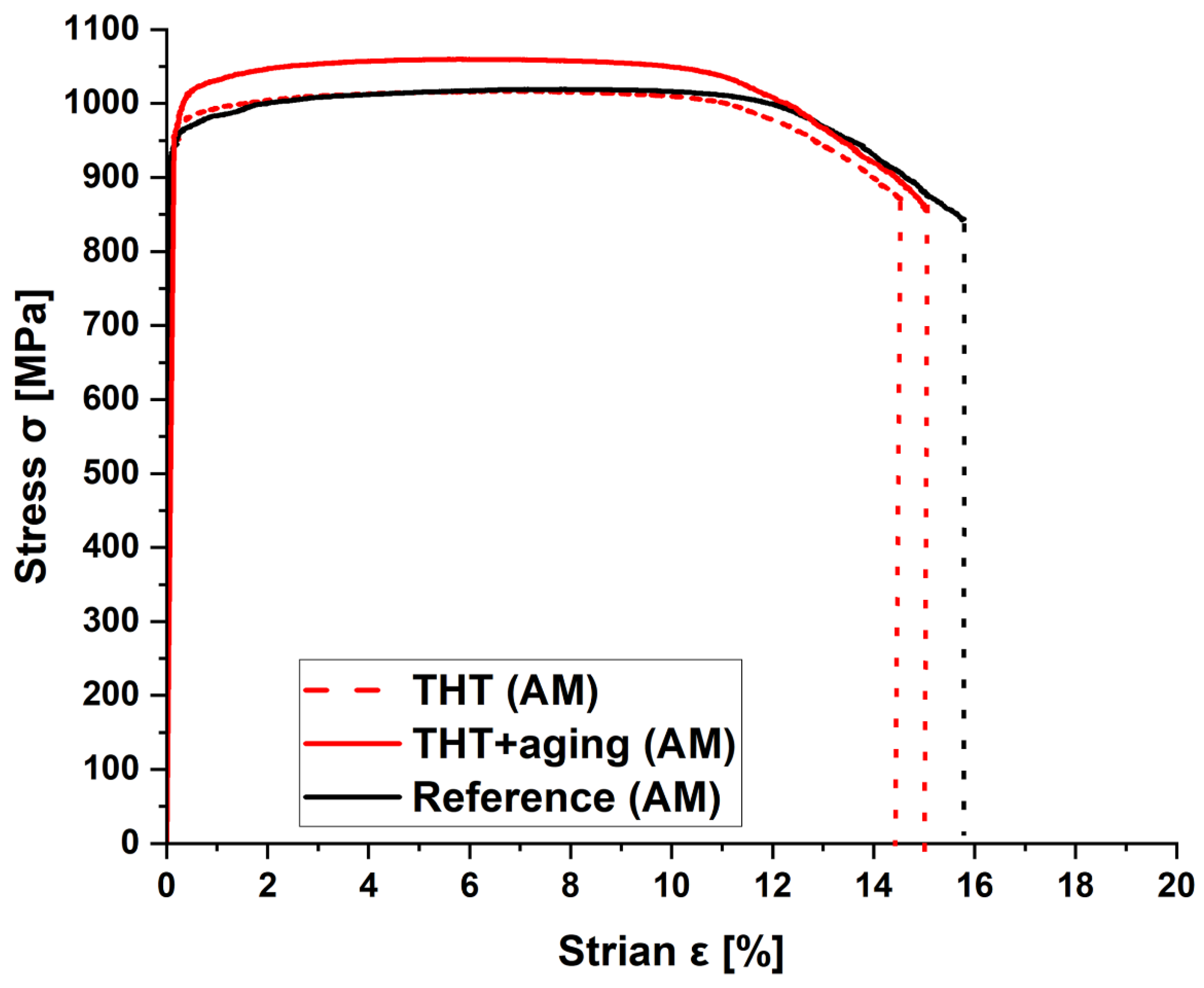
To evaluate the quasi-static properties, stress-strain diagrams of the material states after THT with and without subsequent ageing were recorded and compared with the reference state (Figure 9).
The results of the tensile test show three σ-ε curves without pronounced yield strength. Table 5 summarizes the characteristic values, which can be derived from the σ-ε diagram.
The summary of the results from the tensile test (Table 5) shows that THT without aging has no significant influence on the mechanical properties under quasi-static loading. The yield strength is reduced by 2 % compared to the reference, while the elongation at break increases by 3 %. In contrast, THT with subsequent aging increases the Young's modulus (5 %), tensile strength (3 %) and yield strength (5 %), while the elongation remains nearly unchanged. These observations lead to the conclusion that reference condition is already very well-engineered, because it shows excellent mechanical properties under quasi-static loading and seems to be well controlled since the scatter of the results is low.

3.2.5. Wöhler curves

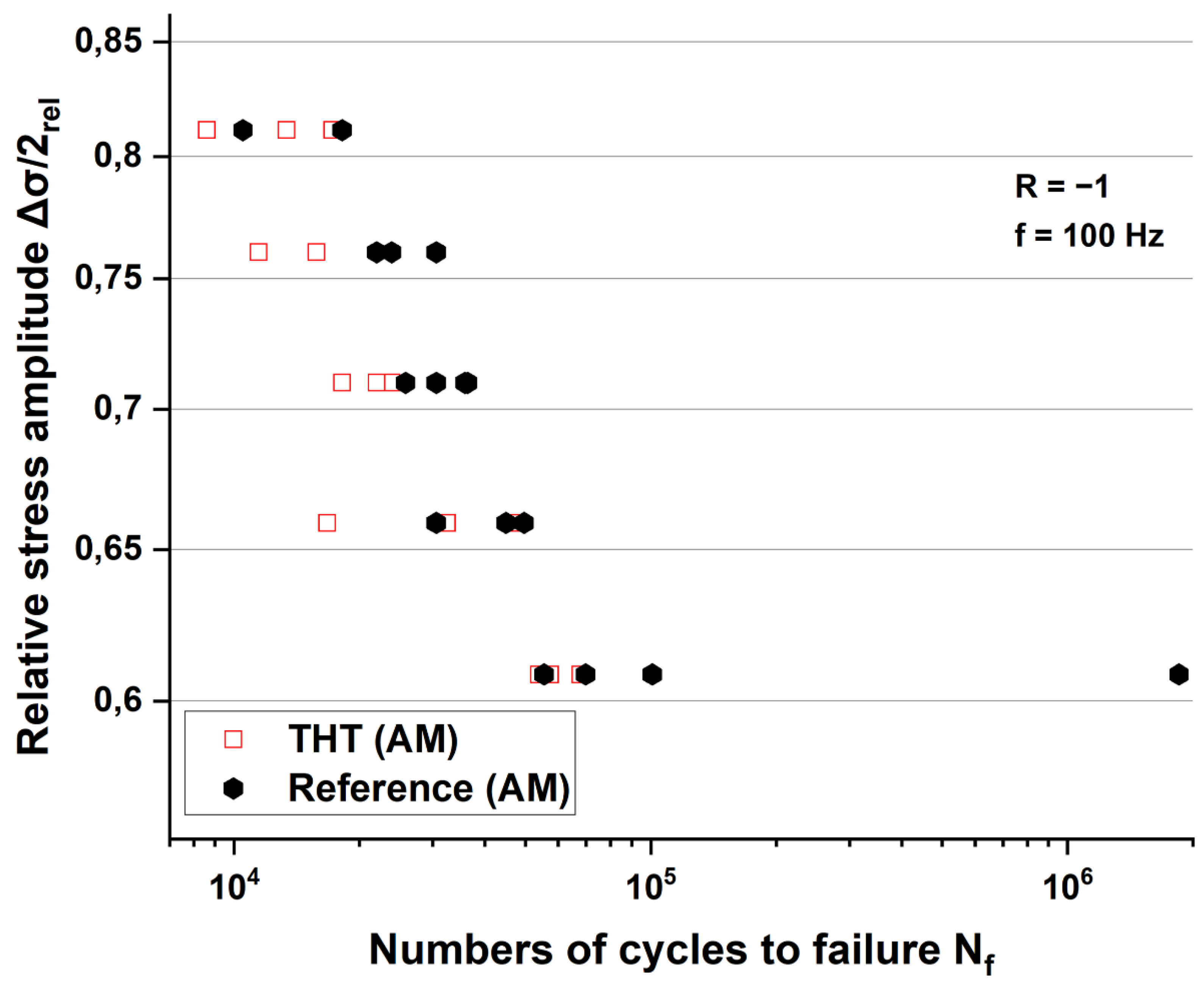
Figure 10 shows the fatigue life data determined in the rotating bending test on the THT and the reference condition. Results of the THT+aging condition are missing since the number of available specimens was limited. Due to the additional and time-consuming step of aging the resulting mechanical properties after THT without aging were of primary interest.
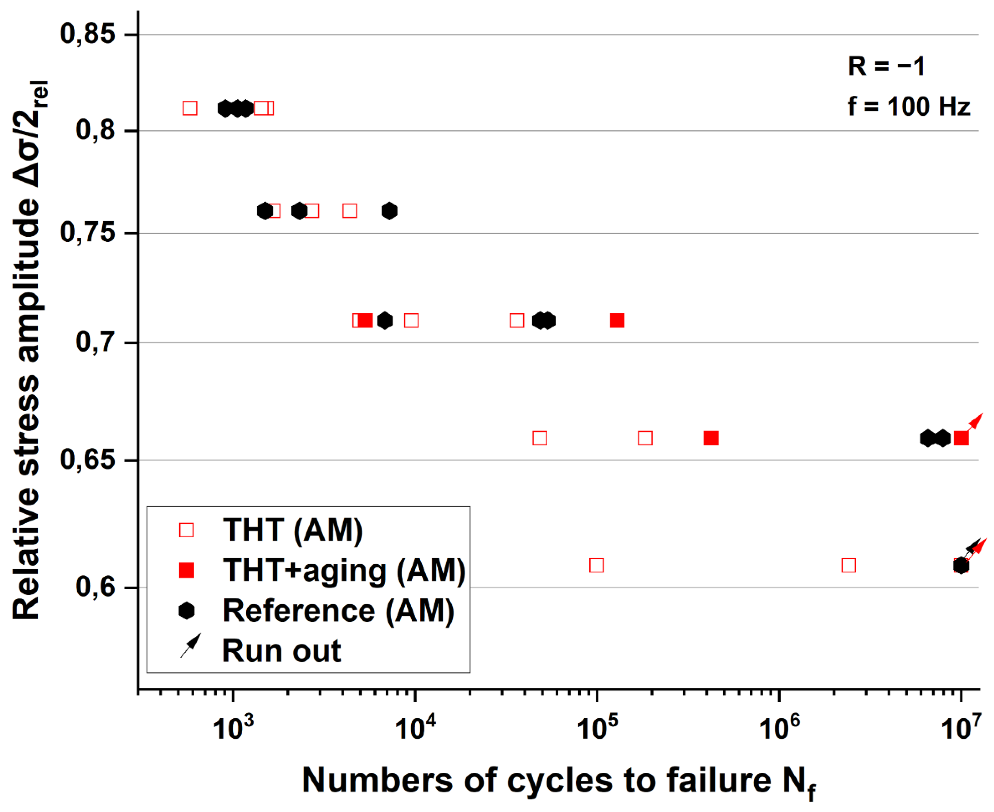
Figure 10 shows that THT without aging does not improve the fatigue properties under rotating bending compared to the reference condition. On the contrary, the fatigue strength of the THT specimens in the transition from short-term to long-term strength is even 7 % lower. This observation supports the assumption, that in terms of the resulting fatigue properties at rotating bending, the reference condition is satisfying enough and cannot be improved by THT without aging. Nevertheless, the influence of THT on the material behaviour in fatigue strength tests is to be investigated. The Wöhler curves determined at rotating bending can be compared with the results from Wu et al. [45]. Figure 11 shows the fatigue life data determined from the fatigue test, which was carried out on shows the data obtained from the fatigue test, which was carried out on samples after THT and on a reduced number of samples in the condition THT+aging.
According to Figure 11, for all stress amplitudes investigated, the THT condition does not exhibit a higher average fatigue life compared to the other conditions. Due to the limited number of specimens, the THT+aging specimens could only be investigated at two stress amplitudes of interest. Therefore, the statistical validation of the results is limited to these stress amplitudes. In the low cycle fatigue area the fatigue strength is 1 % higher for THT+aging than for the reference (at Nf=104, Nf=5∙104 and Nf=106 cycles), while the fatigue life is at least increased by 31 % (Δσ/2≈ 0.66) to 38 % (Δσ/2≈ 0.71). In contrast, no improvement is observed for the specimens after THT without aging compared to the reference. The limiting number of cycles to failure of 107 (Nf) for the THT+aging condition is exceeded at a maximum stress amplitude of Δσ/2≈ 0.66. For the reference as well as for the THT condition without aging this happens at a maximum of Δσ/2≈ 0.61. Thus, the maximum stress amplitude at the limiting number of cycles to failure of 107 is 8 % higher for the THT+aging condition. This indicates that THT with subsequent aging can improve the mechanical properties under cyclic loading. The comparison of the results of the conventional specimens from ref. [37] with the results of the AM specimens shows that the fatigue strength of all conditions is two times higher. This observation can be justified by the fact that the lamella width in the AM reference condition is 10 times smaller. This fact indicates that the conducted additive manufacturing process already allows the production of components with excellent mechanical properties under cyclic loading. In addition, the fatigue data of the reference condition show a lower scatter of fatigue life than for conventionally manufactured specimens from ref. [37]. With at least three specimens per stress amplitude, the deviation is 12 – 88 % and 58 – 139 % for the conventionally manufactured specimens. A possible explanation for the low scatter and the improved properties of the reference specimens under cyclic loading may also be due to the higher original surface quality of Ra=0.5±0.2. Moreover, the Wöhler curves presented here are comparable to the Wöhler curves from Hines [46] (conventional manufactured Ti–6Al–4V) and Paramore et al. [41] (additively manufactured Ti–6Al–4V with THT). This means that AM samples show comparable fatigue properties as conventionally manufactured samples.

3.2.6. TEM investigations

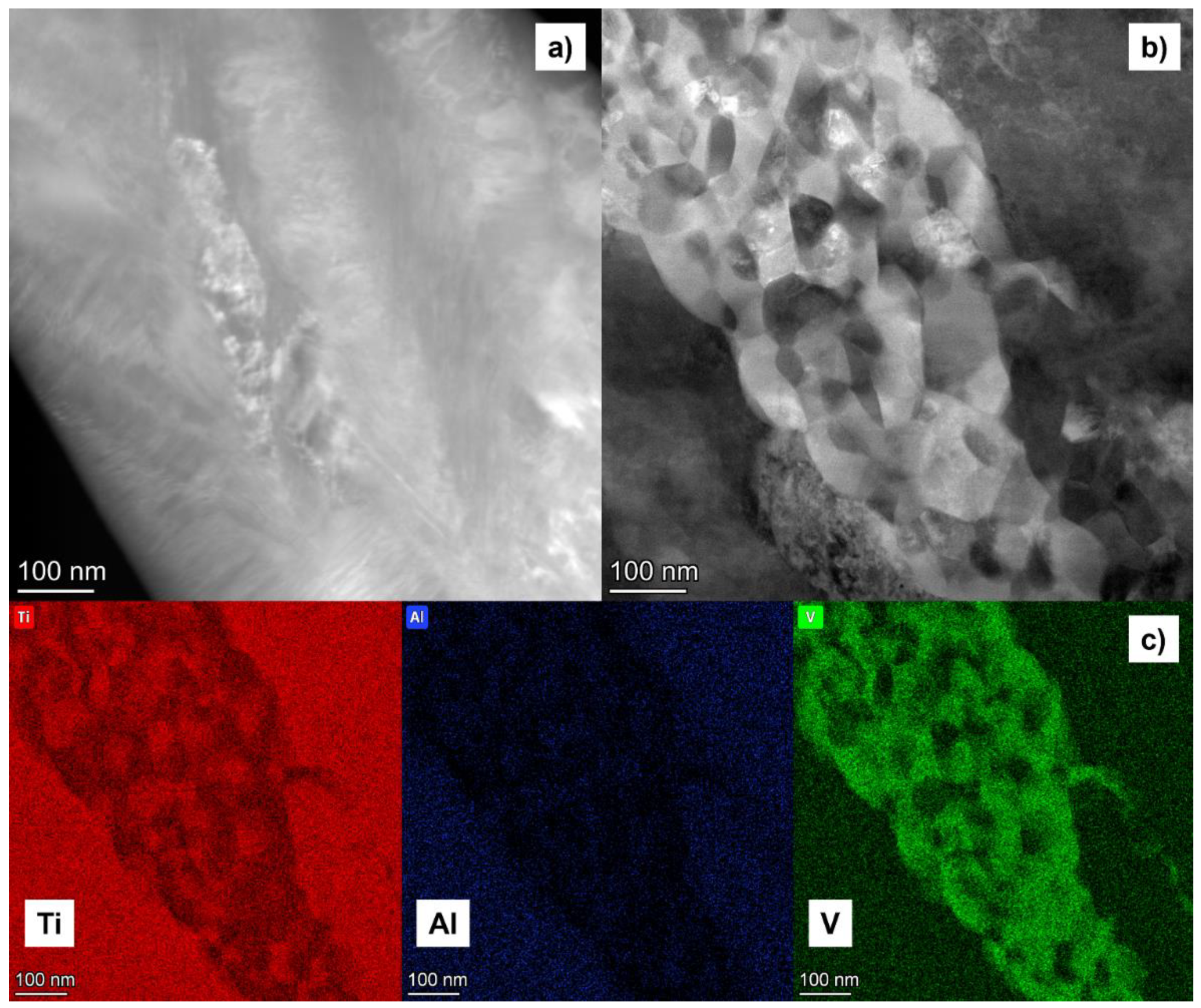
The corresponding phase analysis after THT is depicted in Figure 12 a) and b) in terms of TEM micrographs. To determine the chemical composition of the precipitates the results of the STEM-EDX measurements are shown in Figure 12 c).
Figure 12 a) and b) shows a closeup of the α phase and possible precipitates within the two conditions. At the reference (Figure 12 a)) there is only a slight change of the chemical composition, whereas the THT+aging condition exhibits regions with precipitates (Figure 12 b)) that are not observable at the reference condition. The EDX analysis (Figure 12 c)) shows that the precipitates from Figure 12 b) boast an elevated V concentration comparable to ref. [47]. According to Wang and Li [48] this indicates that the precipitates are secondary α (αs) particles. Peters and Lütjering [49] observed that the presence of αs, which was formed after a thermomechanical treatment including aging at 580°C for 8 h, increases the fatigue life by 9 % in the β titanium alloy Beta-CEZ (Ti-5Al-2Cr-1Fe-4Mo-2Sn). Therefore, it can be assumed that the precipitates shown in Figure 12 b) are the cause of the increase in fatigue life and limit. In comparison to the results of [49] the temporary hydrogenation of the specimens seems to reduce the aging time and temperature needed for a formation of αs, which may be due to the increased number of nucleation sites at the sites of the formerly formed hydrates.

4. Conclusion and Outlook

To evaluate the transferability of microstructural grading via THT a conventionally manufactured tube-like specimen with variable wall thickness was investigated. The resulting microstructure was validated by means of hardness curves (Figure 4), and the stereological parameters were determined from SEM images (Figure 5 and Table 2). It was not possible to determine the tensile and fatigue strength, as the pipe specimen geometry did not allow a required reliable test. The results of the hardness measurements show an increased hardness due to the THT process, with an average increase of 0.5 – 12 % (2 mm wall thickness) and 1 – 9 % (1 mm wall thickness) compared to the reference. The hardness decreases from the surface to the center of the specimen by 15 %±3 % (2 mm) and 25 %±4 % (1 mm). For the THT condition, the stereological parameters demonstrate an average increase in the α lamella width from the surface to the specimen’s center by 38 % (2 mm) - 44 % (1 mm) and in the α colony width by 12 % (1 mm) - 73 % (2 mm). Compared to the reference, the α lamella width at the same location is lower by 19 % (2 mm) - 50 % (1 mm) and the α colony width by 34 % (2 mm). Only the α colony width at 1 mm wall thickness is 6 % larger for the THT condition than the reference. Nevertheless, the reduction of the lamella (colony) width can be assumed to be responsible for the hardness increase.
To evaluate the mechanical properties of a microstructural grading performed on AM Ti–6Al–4V specimens using THT, quasi-static tensile tests were conducted to characterize the stress-strain behavior at quasi-static loading. Besides rotating bending tests and cyclic tests under cyclic loading were carried out to determine Wöhler curves. The investigation shows that the yield strength and tensile strength under quasi-static loading are not significantly influenced by THT either without or with subsequent aging. However, the application of THT shows a positive effect on the elongation at break. The resulting fatigue properties at rotating bending are not improved by THT without aging. The fatigue life can be significantly increased (up to 38 %) by THT with aging treatment. Compared to conventionally manufactured specimens the needed aging temperature is lower for AM specimens and the time is shorter. The cause for the positive effect of THT can be traced back to an increased formation of αs precipitates in the surface near region, which were nucleated at the sites of the former hydrates. The V-rich phase regions were detected by means of TEM analysis and are assumed to increase of the crack initiation resistance. In addition, the aging time and temperature could be reduced by 25% (t) and 4% (T), respectively, by using an upstream THT. As outlook, the V-rich phase regions in Figure 12 should be investigated using the selected area diffraction (SAD) method in the TEM to check whether they can actually be the αs phase [51]. Moreover the determination of the phase fractions can be done by t-EBSD [52].

Author Contributions

Conceptualization, C.S.; methodology, C.S.; software, C.S..; validation, C.S., H.C. and A.H.; formal analysis, C.S. and H.C.; investigation, C.S.; resources, C.S.; data curation, C.S.; writing—original draft preparation, C.S.; visualization, C.S.; writing—review and editing, H.C. and A.H.; project administration, H.C.; funding acquisition, H.C. and C.S, supervision, H.C. and A.H.; All authors have read and agreed to the published version of the manuscript.

Funding

This research was funded by the DEUTSCHE FORSCHUNGSGEMEINSCHAFT, Bonn, Germany (project 470236376) and a scholarship of the STIFTUNG DER DEUTSCHEN WIRTSCHSFT (SDW), Berlin, Germany.

Institutional Review Board Conditionment

Not applicable.

Informed Consent Conditionment

Not applicable.

Data Availability Conditionment

The data that support the finding of this study are available from the corresponding author upon reasonable request.

Acknowledgments

Special thanks go to OTTO FUCHS KG, MACDERMID ENTHONE GMBH and ATOTECH GERMANY GMBH for providing specimens and consumables free of charge plus the Micro- and Nanoanalytics Facility Siegen (MNaF) for supporting the characterization of materials. We acknowledge the support in experimental implementation by Maximilian Butzkamm, Florian Loebich, Simon Ortmann and Durga Venkata Satish Antarvedipalem as well as Julian Müller, Steven Schellert and Matthias Weber for their support at the TEM specimen preparation and investigation.

Conflicts of Interest

The authors declare no conflict of interest.

References

  1. Foust, M., Thomsen, D., Stickles, R., Cooper, C., Dodds, W., Development of the GE aviation low emissions TAPS combustor for next generation aircraft engines, In: , Aerospace Sciences Meetings, 50th AIAA Aerospace Sciences Meeting including the New Horizons Forum and Aerospace Exposition, Nashville, TN, USA, 2012, AIAA 2012-0936.
  2. Niinomi, M., Williams, J. C., Properties and applications ot Ti: Current status and future needs: Precipitation and recristallisation behaviour of cold deformed beta titanium alloys during continous heat treatment, In: Lütjering, G., Albrecht, J. (Hrsg.), Ti-2003 – Science and technology, Proceedings of the 10th world conference on titanium, 13.–18. Juli 2003, Hamburg, Wiley-VCH, Weinheim, 2004, p. 93–110.
  3. Lee, E. W., Frazier, W., Kim, N. J., Jata K., Light weight alloys for aerospace applications IV, TMS, Warrendale, PA, USA, , 1997.
  4. Lütjering, G., Williams, J. C., Titanium, Springer, Berlin-Heidelberg, 2. Aufl., 2007.
  5. Macin, V., Christ, H.-J., Influence of hydride-induced microstructure modification on mechanical properties of metastable beta titanium alloy Ti 10V–2Fe–3Al, International Journal of Hydrogen Energy, 40 (47), 2015, p. 16878–16891. [CrossRef]
  6. Senkov, O. N., Froes, F. H., Beneficial effect of hydrogen as a temporary alloying element on processing, In: Lütjering, G., Albrecht, J. (Hrsg.), Ti-2003 – Science and technology, Proceedings of the 10th world conference on titanium, 13.–18. Juli 2003, Hamburg, Wiley-VCH, Weinheim, 2004, p. 1345–1352.
  7. Piskovets, V. M., Effect of thermohydrogen treatment on mechanical and process properties of low-carbon steel, Metal Science and Heat Treatment, 49 5-6, 2007, p. 301–303. [CrossRef]
  8. Senkov, O. N., Jonas, J. J., Froes, F. H., Recent advances in the thermohydrogen processing of titanium alloys, Journal of the Minerals, Metals & Materials Society, 48 (7), 1996, p. 42–47. [CrossRef]
  9. Dunstan, M. K., Paramore, J. D., Fang, Z. Z., Sun, P., Manipulation of microstructure and mechanical properties during dehydrogenation of hydrogen-sintered Ti–6Al–4V, Materials Science and Engineering A, 764, 2019, p. 138244. [CrossRef]
  10. Macin, V., Schmidt, P., Christ, H.-J., THT of high strength beta titanium alloy Ti–10V–2Fe–3Al, In: Somerday, B. P., Sofronis, P. (Hrsg.), Hydrogen-materials interactions, Proceedings of the international hydrogen conference 2012, 9.–12. Sept. 2012, Jackson Lake Lodge, Moran, WY, USA, ASME Press, New York, USA, 2014, p. 669–676.
  11. Il'in, A. A., Polkin, I. S., Mamonov, A. M., Nosov, V. K., Thermohydrogen treatment - the base of hydrogen technology of titanium alloys, In: Blenkinsop, P. A., Evans, W. J., Flower, H. M. (Hrsg.), Titanium'95 – Science and Technology, Proceedings of the 8th international conference on titanium, 22.–26. Okt. 1995, Birmingham, UK, Institute of Materials, London, UK, 3. Aufl., 1996, p. 2462–2469.
  12. Senkov, O. N., F.H. Froes, Thermohydrogen processing of titanium alloys, International Journal of Hydrogen Energy, 24 (6), 1999, p. 565–576. [CrossRef]
  13. Senkov, O. N., Froes, F. H., Thermohydrogen processing of titanium alloys, In: Goltsov, V. A. (Hrsg.), Progress in Hydrogen Treatment of Materials, Kassiopeya Ltd., Donetsk, Ukraine, 2001.
  14. Sun, Z., Zhou, W., Hou, H., Strengthening of Ti–6Al–4V alloys by thermohydrogen processing, International Journal of Hydrogen Energy, 34 (4), 2009, p. 1971–1976. [CrossRef]
  15. Schmidt, C. D., Christ, H.-J., Hehl, A. von, Hydrogen as a temporary alloying element for establishing specific microstructural gradients in Ti–6Al–4V, Metals, 12 (8), 2022, p. 1267. [CrossRef]
  16. Dunstan, M. K., Vaughn, M. O., Paramore, J. D., Butler, B. G., Kudzal, A. D., Hemker, K. J., Optimization of microstructural manipulation and ductility in laser powder bed fusion Ti-6Al-4V through hydrogen heat treatments, Materials Science and Engineering A, 873, 2023, p. 145061. [CrossRef]
  17. Dunstan, M. K., Microstrucutre – mechanical property relationships in HSPT TI-6AL-4V, Dissertation, University of Utah, Salt Lake City, 2018.
  18. Sun, P., Fang, Z. Z., Koopman, M., Paramore, J., Chandran, K. R., Ren, Y., Lu, J., An experimental study of the (Ti–6Al–4V)–xH phase diagram using in situ synchrotron XRD and TGA/DSC techniques, Acta Materialia, 84, 2015, p. 29–41. [CrossRef]
  19. Sun, P., Fang, Z. Z., Koopman, M., Xia, Y., Paramore, J., Ravi Chandran, K. S., Ren, Y., Lu, J., Phase transformations and formation of ultra-fine microstructure during hydrogen sintering and phase transformation (HSPT) processing of Ti–6Al–4V, Metallurgical and Materials Transactions A, 46 (12), 2015, p. 5546–5560. [CrossRef]
  20. Bohner, F., Gregory, J. K., Mechanical behavior of a graded aluminum alloy, Materials Science Forum, 308-311, 1999, p. 313–318. [CrossRef]
  21. Bohner, F., Gregory, J. K., Fracture in notched parts with a microstructural gradient, In: Trumble, K., Bowman, K., Reimanis, I. E., Sampath, S. (Hrsg.), Functionally graded materials 2000, American Ceramic Society, Westerville, OH, USA, 1. Aufl., 2001, p. 773–781.
  22. Schulze, V., Modern mechanical surface treatment, Wiley-VCH, Weinheim, 2006.
  23. Berg, A., Kiese, J., Wagner, L., Microstructural gradients in Ti–3Al–8V–6Cr–4Zr–4Mo for excellent HCF strength and toughness, Materials Science and Engineering A, 243 (1), 1998, p. 146–149. [CrossRef]
  24. Wagner, L., Mechanical surface treatments on titanium, aluminum and magnesium alloys, Materials Science and Engineering A, 263 (2), 1999, p. 210–216. [CrossRef]
  25. Wagner, L., Gregory, J. K., Thermomechanical surface treatment of titanium alloys, Materials Science Forum, 163-165, 1994, p. 159–172. [CrossRef]
  26. Berg, A., Kiese, J., Wagner, L., Crack propagation in gradient microstructures in titanium alloys, In: Lee, E. W., Frazier, W., Kim, N. J., Jata K. (Hrsg.), Light weight alloys for aerospace applications IV, TMS, Warrendale, PA, USA, 1. Aufl., 1997, p. 207–216.
  27. Drechsler, A., Dörr, T., Kiese, J., Wagner, L., Mechanical and thermomechanical surface treatments to enhance HCF strength in high-strength β titanium alloys, In: Lee, E. W., Frazier, W., Kim, N. J., Jata K. (Hrsg.), Light weight alloys for aerospace applications IV, TMS, Warrendale, PA, USA, 1. Aufl., 1997, p. 151–161.
  28. Froes, F. H., Eylon, D., Suryanarayana, C., Thermochemical processing of titanium alloys, Journal of the Minerals, Metals & Materials Society, 42 (3), 1990, p. 26–29. [CrossRef]
  29. Gammeltoft-Hansen, N., Munch, S. S., Jellesen, M. S., Somers, M. A. J., Christiansen, T. L., Characterization of thermochemically surface-hardened titanium by light optical microscopy, Materials Performance and Characterization, 6 (3), 2017, p. 20160083. [CrossRef]
  30. Valente, E. H., Jellesen, M. S., Somers, M. A. J., Christiansen, T. L., Gaseous surface hardening of Ti–6Al–4V fabricated by selective laser melting, Surface and Coatings Technology, 383, 2020, p. 125278. [CrossRef]
  31. Meng, Y., Villa, M., Dahl, K. V., Wang, B., Drouet, M., Dubois, J.-B., Somers, M. A. J., Christiansen, T. L., Thermochemical surface hardening of Ti–6Al–4V: On the role of temperature and treatment media, Surface and Coatings Technology, 422, 2021, p. 127505. [CrossRef]
  32. Kværndrup, F. B., Kücükyildiz, Ö. C., Winther, G., Somers, M. A., Christiansen, T. L., Extreme hardening of titanium with colossal interstitial contents of nitrogen and oxygen, Materials Science and Engineering A, 813, 2021, p. 141033. [CrossRef]
  33. Sozańska, M., Effect of high-temperature hydrogen treatment on the microstructure and properties of titanium alloy Ti–6Al–4V, Materials Science and Engineering, 22, 2011, p. 1–11. [CrossRef]
  34. Schmidt, C. D., Macin, V., Schmidt, P., Christ, H.-J., Generation of microstructural gradients for improved mechanical properties via thermohydrogen treatment of the metastable beta titanium alloys Beta C and Ti 10V–2Fe–3Al, MATEC Web of Conferences, 321, 2020, p. 12017. [CrossRef]
  35. Schmidt, C. D., Christ, H.-J., Determination of material characteristics for hydrogen uptake and release of titanium alloys as basis for the design of a THT process (Part 2), In: J. B. Langer und M. Wächter (Hrsg.), Werkstoffe und Bauteile auf dem Prüfstand, Tagungsband zur Werkstoffprüfung 2020, 3.–4. Dez. 2020, online, Berlin, 2020, p. 185–190.
  36. Berg, A., Wagner, L., Near-surface gradient microstructures in metastable beta-titanium alloys for improved fatigue performance, Materials Science Forum, 308-311, 1999, p. 307–312. [CrossRef]
  37. Schmidt, C. D., Christ, H.-J., Hehl, A. von, Fatigue properties of microstructural gradients in Ti–6Al–4V generated with thermohydrogen treatment, In: Zimmermann, M. (Hrsg.), Werkstoffe und Bauteile auf dem Prüfstand, Tagungsband zur Werkstoffprüfung 2022, DGM, Sankt Augustin, Germany, 2022, p. 294–299.
  38. Niinomi, M., Gong, B., Kobayashi, T., Ohyabu, Y., Toriyama, O., Fracture characteristics of Ti–6Al–4V and Ti–5Al–2.5Fe with refined microstructure using hydrogen, Metallurgical and Materials Transactions A, 26 (5), 1995, p. 1141–1151. [CrossRef]
  39. Oshida, Y., Bioscience and bioengineering of titanium materials, Elsevier, London, 2. Aufl., 2013.
  40. Costa, J. E., Banerjee, D., Williams, J. C., Hydrogen effects in beta-titanium alloys, In: Boyer, R. R., Rosenberg, H. W. (Hrsg.), Beta titanium alloys in the 1980's, TMS-AIME, Warrendale, PA, USA, 1984, p. 69–84.
  41. Paramore, J. D., Fang, Z. Z., Dunstan, M., Sun, P., Butler, B. G., Hydrogen-enabled microstructure and fatigue strength engineering of titanium alloys, Scientific Reports, 7 (1), 2017, p. 41444. [CrossRef]
  42. Numakura, H., Koiwa, M., Hydride precipitation in titanium, In: Ashby, M. F., Hirth, J. P. (Hrsg.), Perspectives in hydrogen in metals, Pergamon Press, Oxford, UK, 1986, p. 501–509.
  43. Kerr, W. R., The effect of hydrogen as a temporary alloying element on the microstructure and tensile properties of Ti–6Al–4V, Metallurgical Transactions A, 16 (6), 1985, p. 1077–1087. [CrossRef]
  44. Guitar, A., Vigna, G., Luppo, M. I., Microstructure and tensile properties after thermohydrogen processing of Ti–6Al–4V, Journal of the Mechanical Behavior of Biomedical Materials, 2 (2), 2009, p. 156–163. [CrossRef]
  45. Wu, Z., He, Z., Wu, S., Gao, X., Lei, L., Liu, C., Chen, B., Dong, C., Rotating bending fatigue mechanisms of L-PBF manufactured Ti-6Al-4V alloys using in situ X-ray tomography, International Journal of Fatigue, 176, 2023, p. 107876. [CrossRef]
  46. Hines, J. A., Propagation of microcracks at stress amplitudes below the conventional fatigue limit in Ti–6Al–4V, Fatigue Fracture of Engineering Materials and Structures, 22 (8), 1999, p. 657. [CrossRef]
  47. Qazi, J. I., Rahim, J., Senkov, O. N., Froes, F. H., Phase transformations in the Ti–6Al–4V–H system, Journal of the Minerals, Metals & Materials Society, 54 (2), 2002, p. 68–71. [CrossRef]
  48. Wang, K., Li, M. Q., Morphology and crystallographic orientation of the secondary α phase in a compressed α/β titanium alloy, Scripta Materialia, 68 (12), 2013, p. 964–967. [CrossRef]
  49. Peters, J. O., Lütjering, G., Comparison of the fatigue and fracture of α+β and β titanium alloys, Metallurgical and Materials Transactions A, 32 (11), 2001, p. 2805–2818. [CrossRef]
  50. Atzori, B., Meneghetti, G., Susmel, L., Material fatigue properties for assessing mechanical components weakened by notches and defects, Fatigue & Fracture of Engineering Materials & Structures, 28 1-2, 2005, p. 83–97. [CrossRef]
  51. Banerjee, R., Nag, S., Stechschulte, J., Fraser, H. L., Strengthening mechanisms in Ti–Nb–Zr–Ta and Ti–Mo–Zr–Fe orthopaedic alloys, Biomaterials, 25 (17), 2004, p. 3413–3419. [CrossRef]
  52. Koblischka-Veneva, A., Koblischka, M. R., Schmauch, J., Noudem, J., Murakami, M., Analysis of the microstructure of bulk MgB2 using TEM, EBSD and t-EBSD, Journal of microscopy, 274 (3), 2019, p. 123–131. [CrossRef]
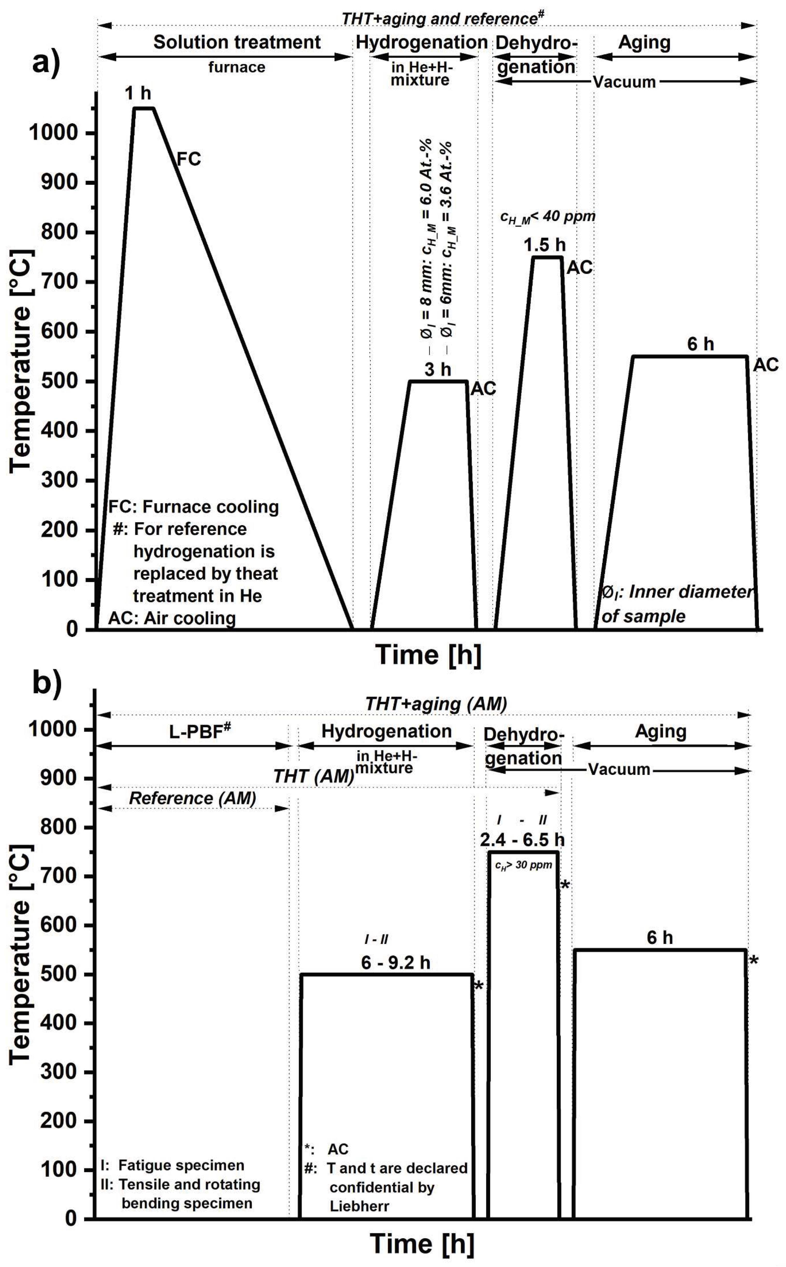
Figure 1. Schematic temperature-time curve for the generation of the THT and the reference condition of the conventionally manufactured tube-like specimens (a) and the AM specimens (b).
Preprints 96257 g001
Figure 2. Calculated 2-D H concentration profiles estimated by FEM after hydrogenation of the tube-like specimen at the one end with 2 mm (a) cH_M = 3.6 at.%, tH_sim = 2 s) and at the other end with 1 mm (b) cH_M = 6.0 at.%, tH_sim = 6 s) wall thickness.
Preprints 96257 g002
Figure 3. FEM-estimated 3-D H concentration profile after hydrogenation of the tube-like specimen (cH_M = 3.6 at.% in the segment with 2 mm wall thickness, cH_M = 6.0 at.% in the segment with 1 mm wall thickness, tH_sim = 5 min).
Preprints 96257 g003
Figure 4. Hardness curves after THT+aging and for the reference condition of demonstrators at a) 2 mm and b) 1 mm wall thickness (distance to outer surface).
Preprints 96257 g004
Figure 5. BSE-SEM micrographs at the near surface area of the tube-like specimens after reference heat treatment (a) and (c) and after THT+aging (b) and (d) for both wall thicknesses: (a)-(b): 2 mm, (c)-(d): 1 mm.
Preprints 96257 g005
Figure 6. Calculated 2-D H concentration profile estimated by FEM after hydrogenation of the AM specimens (a) fatigue test specimen: cH_M = 13.7 at.%, tH = 6 h, b) rotating bending/tensile test specimen: cH_M = 14.0 at.%, tH = 9.2 h.
Preprints 96257 g006
Figure 7. Hardness curves after THT+aging and for the reference condition of the AM specimens.
Preprints 96257 g007
Figure 8. BSE-SEM micrographs at the near surface area of the AM specimens after reference heat treatment (a) and after THT (b) and after THT+aging (c).
Preprints 96257 g008
Figure 9. Stress-strain diagrams of the AM specimens determined in quasi-static tensile tests.
Preprints 96257 g009
Figure 10. Fatigue life data from cyclic rotating bending tests on the AM specimens at R=-1 (absolute stress amplitudes declared confidential).
Preprints 96257 g010
Figure 11. Fatigue life data from cyclic deformation tests on the AM specimens at R=-1 (absolute stress amplitudes declared confidential).
Preprints 96257 g011
Figure 12. HAADF-STEM micrograph (chemical contrast) of the surface near region of the reference (a)) and the THT+aging condition (b)) plus EDX mapping of b) (c)).
Preprints 96257 g012
Table 1. Used and calculated parameters of the THT on the tube-like specimens.
Specimen type Hydrogenation Dehydrogenation
tH [h] cH_M [at.%]
inner/outer
ti [s] SCFH tD [h] cH_M [at.%] ti [s] SCFD
Tube-like 3 3.6/6.0 160 23.5 3 0.2 220 14.3
Table 2. Metallographic characteristics of the microstructure according to the reference, after THT and after THT+aging.
Wall thickness Condition α colony width [µm] α lamellar width [µm]
Surface Center Surface Center
2 mm THT+aging 21–156 172–562 2–10 3–12
Reference 64–199 349–376 3–13 3–11
1 mm THT+aging 80–232 128–191 2–17 2–27
Reference 80–244 166–281 6–19 6–25
Table 3. Used and calculated parameters of the THT on the AM specimens.
Specimen type Hydrogenation Dehydrogenation
tH [h] cH_M [At.-%]
Inner/outer
ti [s] SCFH tD [h] cH_M [At.-%] ti [s] SCFD
AM specimens for fatigue 6 13.7 230 16.5 2.4 0.2 220 17.4
and for rotating bending/tensile tests 9.2 14.0 16.8 6.5 0.1
Table 4. Metallographic characteristics of the microstructure of the AM specimens according to the reference, after THT and after THT+aging.
Condition β phase fraction [vol.%] α lamellae width [µm]
Near surface Center Near surface Center
THT 9.6±2.2 11.0±0.1 1.8±0.6 2.3±0.8
THT+aging 7.7±0.1 8.9±1.4 1.5±0.7 2.1±0.6
Reference 6.0±2.3 2.3±0,8
Table 5. Mechanical properties determined in quasi-static tensile tests on three microstructural conditions (number of tests per condition: 3).
Condition Young‘s modulus [GPa] Tensile strength σUTS [MPa] Yield strength σYS [MPa] Percent tensile elongation EL [%]
THT 116 ± 2 1021 ± 3 969 ± 3 16.1 ± 0.1
THT+aging 122 ±1 1056 ± 6 1014 ± 1 16.1 ± 0.7
Reference 115 ± 3 1021 ± 15 986 ± 19 15.6 ± 1.4
Disclaimer/Publisher’s Note: The statements, opinions and data contained in all publications are solely those of the individual author(s) and contributor(s) and not of MDPI and/or the editor(s). MDPI and/or the editor(s) disclaim responsibility for any injury to people or property resulting from any ideas, methods, instructions or products referred to in the content.
Copyright: This open access article is published under a Creative Commons CC BY 4.0 license, which permit the free download, distribution, and reuse, provided that the author and preprint are cited in any reuse.
Prerpints.org logo

Preprints.org is a free preprint server supported by MDPI in Basel, Switzerland.

Subscribe

© 2024 MDPI (Basel, Switzerland) unless otherwise stated