1. Introduction
A suspension control system design focuses on two main objectives: ensuring a comfortable ride and maintaining driving stability. To evaluate a suspension system in terms of these objectives, three measures are commonly used: the vertical acceleration of the sprung mass, suspension stroke, and tire deflection [
1]. Vertical acceleration of the sprung mass is considered as the most important measure for evaluating ride comfort and is assessed using the international standard ISO 2631-1 to determine its effects on passengers [
2,
3]. Driving stability is assessed using the suspension stroke and tire deflection. The relationship between the two objectives and the three measures has been well summarized in the literature [
4,
5]. Ride comfort is related to the motion of the sprung mass, whereas driving stability is related to the motion of an unsprung mass. However, achieving good ride comfort and driving stability simultaneously is challenging. Therefore, most studies have focused on the weight for adjusting the objective function or selecting a performance. Numerous controller design methodologies, including linear quadratic regulator (LQR) [
6], LQ static output feedback control [
7,
8], H∞ control [
9,
10], fuzzy control [
11,
12], adaptive control [
13,
14], back-stepping control [
15,
16], and model predictive control (MPC) [
17,
18], have been proposed and applied to vehicle suspension systems.
The control target of this study is an in-wheel motor vehicle, that is, a vehicle with the motor and power engine of an electric vehicle that can be reduced in size and embedded in each wheel to compensate for the narrow interior space. This is one of the disadvantages of existing internal combustion engine vehicles. This is beneficial because modern vehicles have become multipurpose with recent developments in autonomous driving technology. Because these in-wheel motor vehicles offer the advantage of improved acceleration and climbing ability compared to existing vehicles while enabling free steering, many studies have been conducted on them [
19,
20,
21].
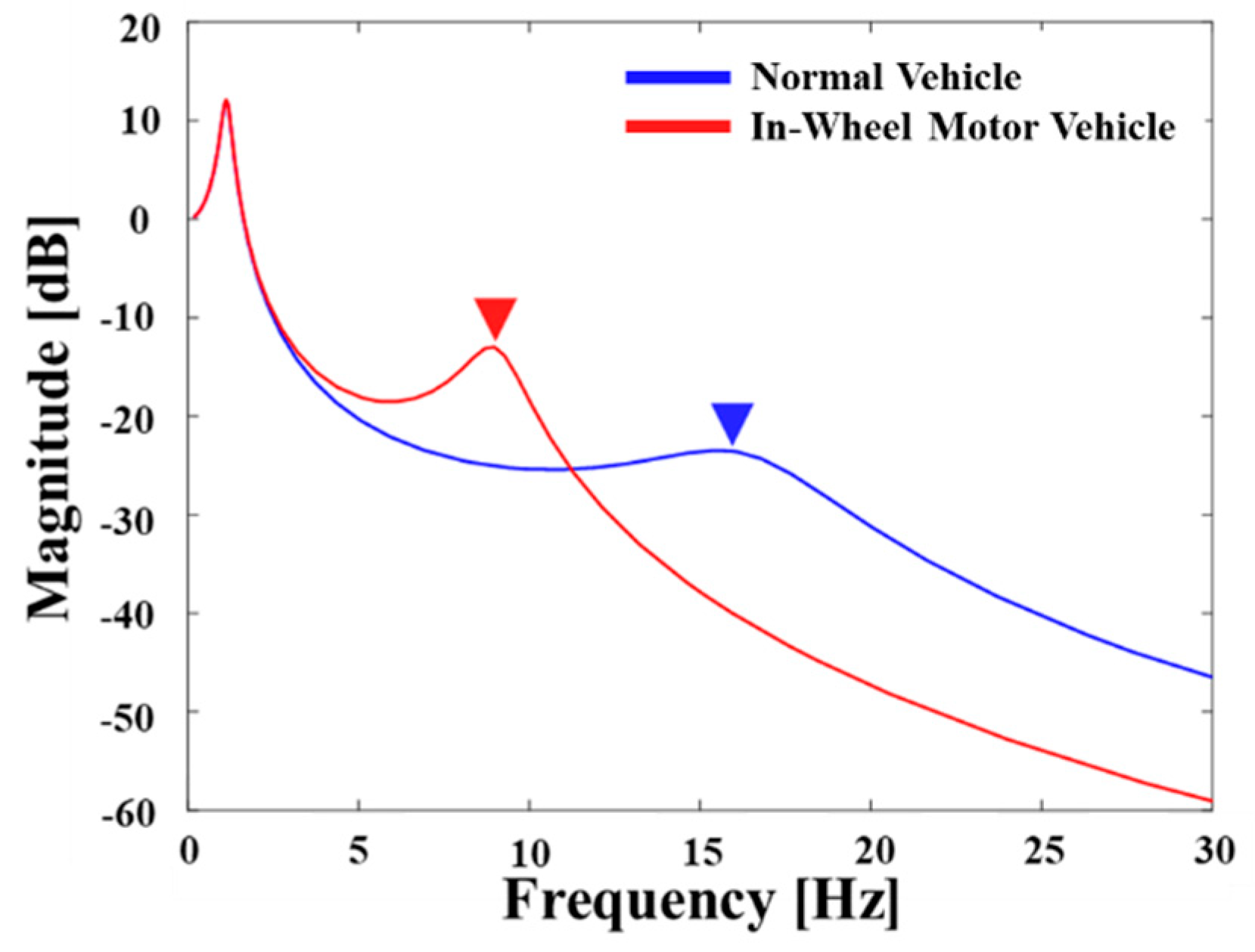
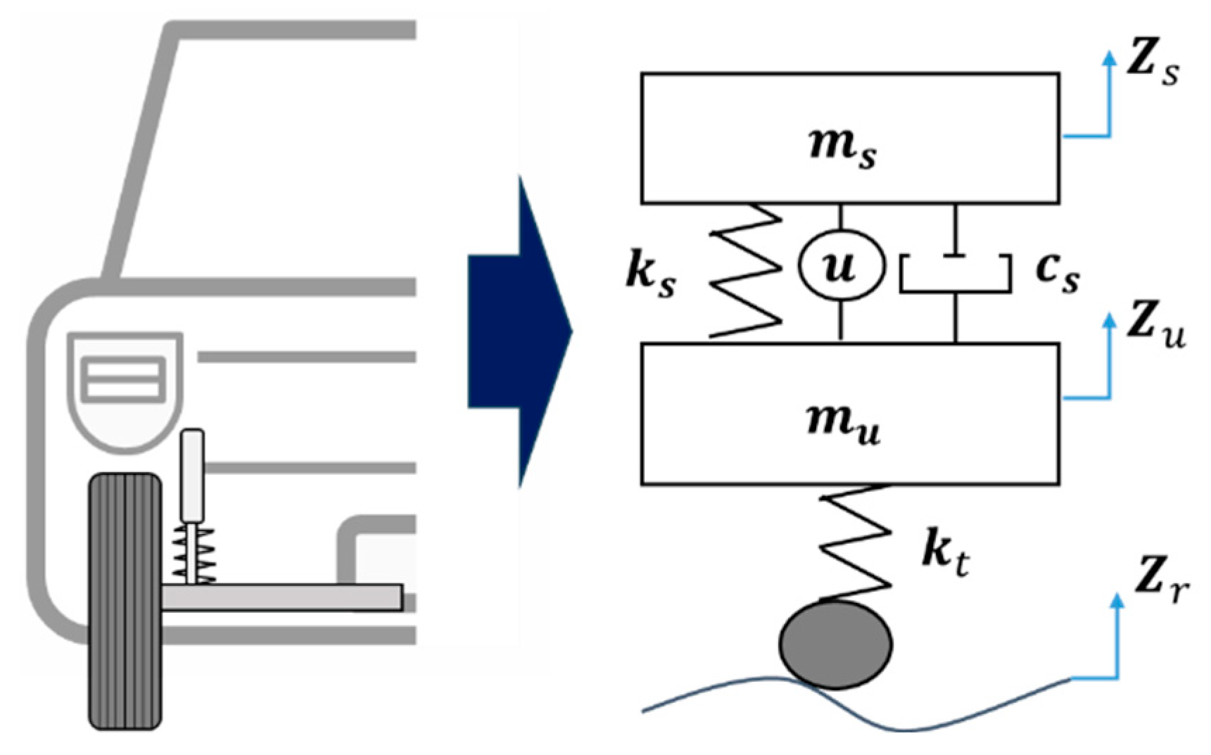
Compared to conventional vehicles, these in-wheel motor vehicles offer several advantages in that the unsprung mass of the vehicle increases several times when the motor is mounted on the wheel. However, they are disadvantageous in terms of ride comfort and vehicle stability. To compare the dynamic characteristics of in-wheel and normal vehicles, the frequency response function is shown in
Figure 1. As evident, a shift in the resonance frequency towards lower values is undesirable. In general road configurations, the roughness of the road surface can increase the wheel motion, thereby compromising vehicle stability and ride comfort [
22,
23]. The increase in wheel mass, particularly in the range of 4–9 Hz wherein humans are sensitive to vertical acceleration, induces higher vibrations [
23]. The Grzegorz Slaski research team from Poznan University conducted real-world tests to demonstrate the degradation of ride comfort in vehicles with increased wheel mass owing to the installation of in-wheel motors. The results indicated that an increase in wheel mass adversely affected ride comfort and driving stability [
23]. Therefore, ride comfort and driving stability may deteriorate owing to wheel mass, which may be fatal to passengers and severely impact vehicles. Thus, this study proposes the use of a road type classification logic designed using data-driven artificial intelligence algorithms. This logic aims to distinguish between off roads, which exhibit a high likelihood of compromised driving stability and paved roads, wherein the ride comfort is a primary concern. Based on this classification, separate control strategies are applied depending upon dynamic characteristics which are different based on the ratio of the sprung mass to the unsprung mass.
Despite a significant issue of this work, the study on the vibration system featuring the in-wheel motor vehicles such as electric car is considerably rare comparing with conventional suspension system in which the sprung mass is much higher than the unsprung mass. Consequently, the main technical contribution of this work is to evaluate vibration control performances of the in-wheel motor vehicles in which the weighting of the unsprung mass is crucial for both the ride comfort and steering stability. In order to achieve this goal, an optimal linear quadratic regulator (LQR) controller is formulated and modified to switch for the paved road and off-road, respectively. In addition, in order to reflect real environmental conditions, the road classification is carried out in this work using both the Long Short-Term Memory (LSTM) and Kalman filter to estimate the road roughness and hence achieve high accuracy through an artificial neural network with a multi-input-single output (MISO) system structure. The proposed control strategy is then simulated using MATLAB/Simulink with the classified road type and vibration control performances at the sprung mass and unsprung mass are evaluated and presented in both frequency and time domains.
3. Road Type Classification Based on LSTM
There are various road type classification logic methods for controller switching [
29,
30]. Harikrishnan et al. used the 3-axial acceleration sensor of a smartphone to determine potholes and bumps using a rule-based method in low-speed (15–20 km/h) vehicles and reported accuracies of at least 65.2–98.4% [
29]. Menegazzo et al. performed classification (dirt, cobblestone, and asphalt) based on artificial neural network algorithms, such as convolutional neural networks (CNNs) and LSTM, using various sensors, including the global positioning system (GPS) and camera sensors. An accuracy of theses was reported by 95.56% [
30]. The LSTM-based classification method exhibits high accuracy through an artificial neural network with a multi-input-single output (MISO) structure. Thus, using various sensor values as the input layer data results in a positive effect on the classification accuracy [
31]. However, securing a large amount of sensor data increases the system design costs, and securing a wide range of sensor data while ignoring the relationship between the input sensor data and decision labels can increase the dimensions and complexity of artificial neural networks. Therefore, in this study, as shown in
Figure 5, following the estimation of the profile of the road using a Kalman filter to estimate the road roughness using two acceleration sensors and one damper relative displacement sensor, an LSTM-based road type classifier was developed using only two inputs: the prediction results and the acceleration sensor of the sprung and unsprung masses.
This study developed a discrete Kalman with unknown input (DKF-UI) using a tire normal force estimator [
32]. The unknown road roughness values applied to the wheels of the quarter-car model were estimated using the DKF-UI model, and the road profile was estimated. Equations (9), (10), (11), (12), and (13) represent the main estimation process of the DKF-UI algorithm. For more detailed information, please refer to our previous studies [
32,
33].
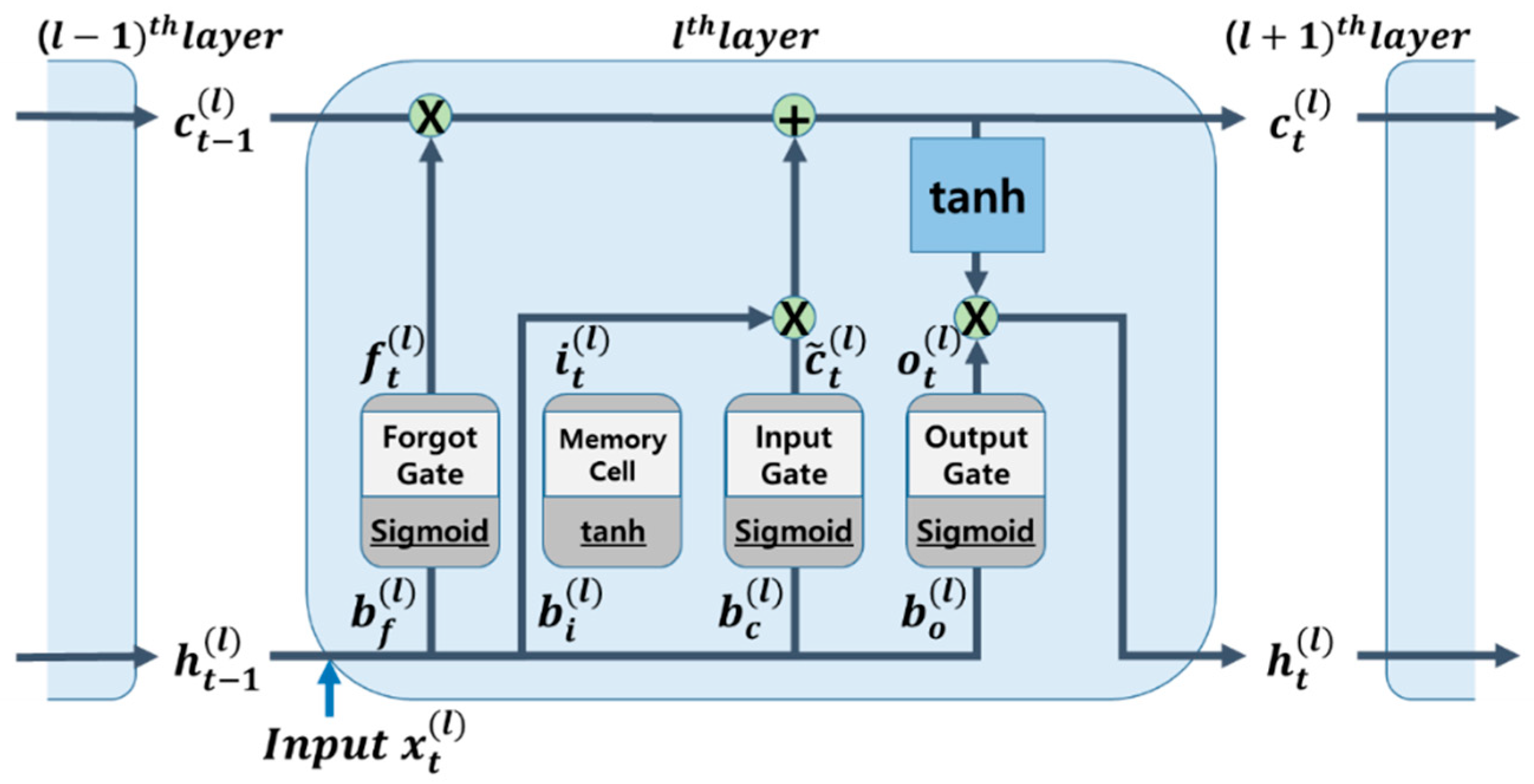
The internal structure of the LSTM model is shown in
Figure 6. It has a circular structure similar to that of the Recurrent Neural Network(RNN) and a complex internal structure. The LSTM cell comprises three gates and one memory cell, where
xt denotes the input,
ht denotes the output at time
t,
ht-1 is the output immediately before
t, and
l denotes the order of the LSTM cells. The data flow is depicted in
Figure 6 by arrows, and the operations between the matrix members are indicated by circles. The entire dataset was divided by window size to obtain the number of cells represented by
n.
- Initialization of parameter at
- Kalman gain calculation
- Unknown input estimation step
The forward propagation process can be expressed as follows [
33]:
- Input gate and new memory
- Cell state
and hidden state
The amount of memory cell content retained can be altered using a forget gate. The forget gate employs a sigmoid function. The weight is multiplied by the output value ht-1 from the previous time, xt enters the LSTM cell at the present moment, and bias bf is then applied. The input to the sigmoid function is the output value.
In this case, the data move on to the following step after being multiplied by
ct-1 while passing through the sigmoid activation function. At time
t-1, the input gate modifies the amount of output that is mirrored in the memory cell. Subsequently, it becomes a new memory and is added to the memory cell if it successfully completes its activation function. The new memory is then multiplied by
ct and passes through the input gate to create
ct. The newly formed
ct is delivered to the following LSTM cell and contains only the required information: The final step involves choosing the export output. The value of this output is filtered based on the cell status. First, it selects the portion of
ct to output as the input data for the sigmoid layer. The output of the previously calculated sigmoid gate is multiplied by
ct before being transmitted through the tanh layer. Consequently, output
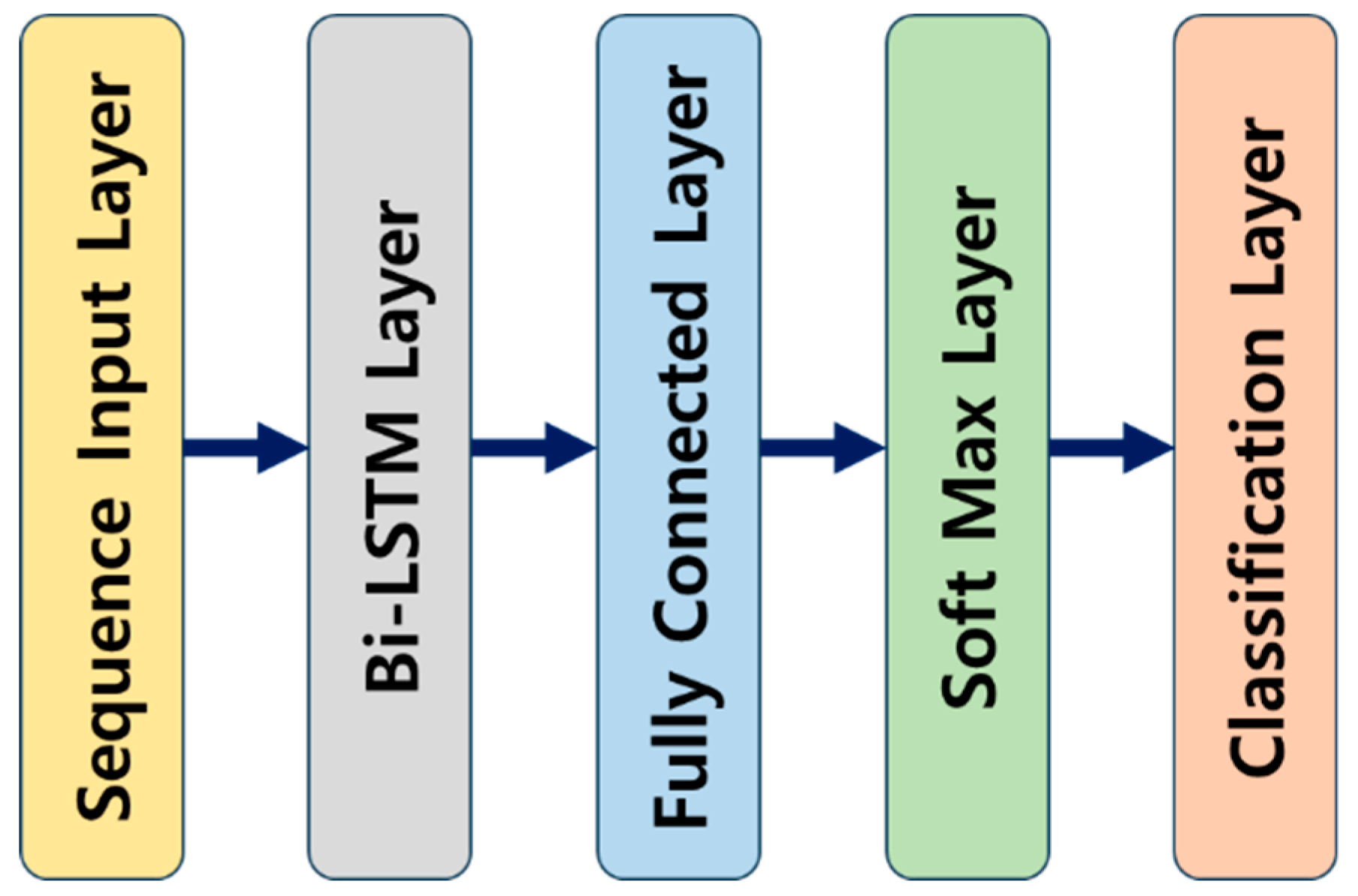
ht of the exported data only includes the desired section. As shown in
Figure 7, the layers used include the sequence input, bi-LSTM, fully connected, softmax, and classification layers, which were designed to classify road types into 200 hidden units.
Table 3 lists the optimal hyperparameters used to train the LSTM artificial neural network. The corresponding hyperparameters were selected through trial and error. In this study, the data used for the LSTM training were generated by designing random roads based on the ISO 8608 standard and were categorized into five grades (A, B, C, D, and E). The road roughness increased from A- to E-class roads. In particular, the E-class road exhibited a level of roughness comparable to that of unpaved roads. Therefore, to differentiate the roads, roads A, B, and C were labeled as paved roads, emphasizing ride-comfort-oriented control, whereas roads D and E, resembling unpaved roads, were labeled for wheel-motion-oriented control. Descriptions of these labels are summarized in
Table 4. The road classifier, developed after training on the given data, was applied to roads that were a mixture of wavy roads with amplitudes of 0.02 m and frequencies of 1, 9, and 15 Hz, combined with the roads used for training, to assess its performance and robustness.
Table 5 presents the results of the artificial neural network derived from the confusion matrices for road type classification on each validation dataset with optimal hyperparameters, in terms of
,
, and
score. These metrics are expressed as follows:
is the ratio of what is actually true to what the neural network model predicts to be true and is also referred to as the positive predictive value.
is the ratio of what the model predicts to be true to what is true and is also referred to as the hit rate. The harmonic average of these two indicators is the
indicator. The higher the number of these three indicators, the better the result. The average of the three performance indicators for the LSTM artificial neural network used in this study was 91.10%, which is good compared with previous studies. As summarized in
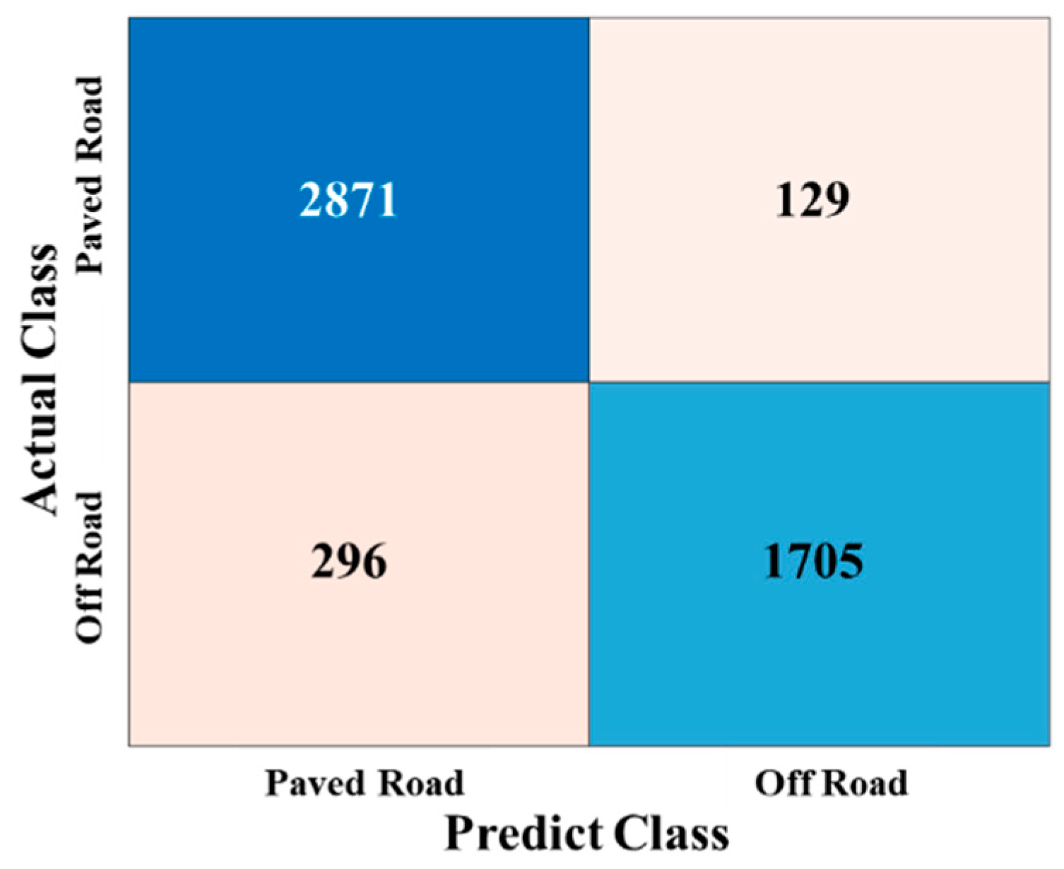
Table 5, the results indicated that combining frequencies lower (1 Hz) or higher (15 Hz) than the wheel resonance frequency (9 Hz) yielded consistently good outcomes. This observation was true even when mixing frequencies on random roads without a specific frequency. Thus, the robustness of the designed LSTM network, independent of the presence or absence of specific frequency components was appropriately demonstrated. Among these results, the confusion matrix for the road mixture with a wavy road wheel resonance frequency (9 Hz), which is representative and has the most significant impact on the target vehicle in this study, is shown in
Figure 8.
The LSTM model, which is capable of learning the periodicity of time series data, demonstrated superior performance in effectively learning the various frequencies present on random roads. Therefore, it was inferred that the model performed well, even on roads composed of a specific frequency of wavy road combinations.
4. Control Results and Discussions
The LSTM-based road type classification and control logic was designed and analyzed using MATLAB and Simulink. Although the LSTM-based road type classification logic exhibited high accuracy, controller switching can cause a chattering problem in the control input. Chattering is an undesirable phenomenon characterized by infinitely fast switching, which may cause equipment damage in real vehicle systems. To avoid its occurrence, many solutions such as integration, moving average filter, and saturation function [
34,
35] have been reported. A chattering-free strategy based on a moving average filter was applied to the proposed control architecture. In this study, we also utilized a moving average filter to prevent excessive chattering and enhance the control performance. To improve the ride comfort and driving stability of in-wheel motor vehicles, road conditions were determined through LSTM, and the control was performed by switching the controller based on the determined road and applying it to the actuator.
The overall flow of the integrated control logic is shown in
Figure 4, as explained earlier. After completing the training, the LSTM network used sensor data and Kalman filter estimates to assess the wheel resonance. Based on this determination, an appropriate controller was selected to perform the control. As described in
Section 2.2, the controller conversion applied the LQR_Paved Road controller to paved roads, and the LQR_Paved Road control logic was switched to the LQR_Off Road control logic to secure the driving stability and ride comfort. This was intended to improve both the ride comfort and driving stability of the in-wheel vehicle. After the control tests, the results were evaluated using various criteria. First, the ride comfort control result was evaluated according to the ISO 2631_Wk standard to numerically express the degree of vibration felt by an occupant while sitting because vertical vibration vibrates throughout the body, which is derived based on the acceleration of the sprung mass. Driving stability was evaluated based on tire deflection. Tire deflection is a numerical value indicating the degree of contact of the wheel with the road, which is calculated as the RMS of the difference between the displacement of the road profile and the unsprung mass. In case of the ISO 2631_Wk (ride comfort) and tire deflection results derived after performing the control, the smaller the number, the better was the result.
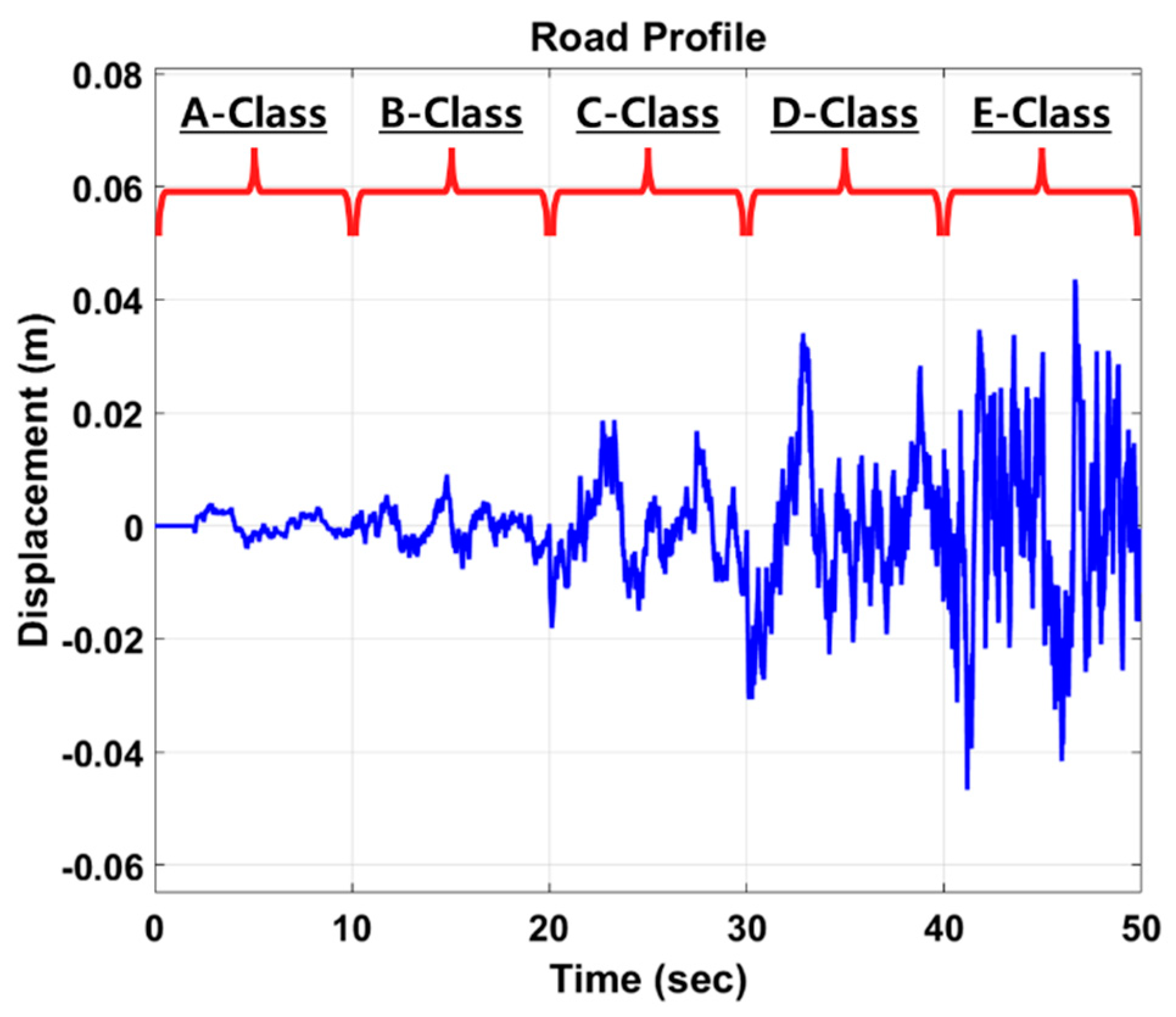
After performing the controller on the road type classification and control strategy, the results were interpreted based on various criteria. Results without control input, control results for LQR_Paved Road and LQR_Off Road, and control results with road type classification and switching controller were obtained and presented. In addition, the roads used in the simulation were set to select A-, B-, C-, D-, and E-class roads, which could be sequentially applied for 10 s each, designed as shown in
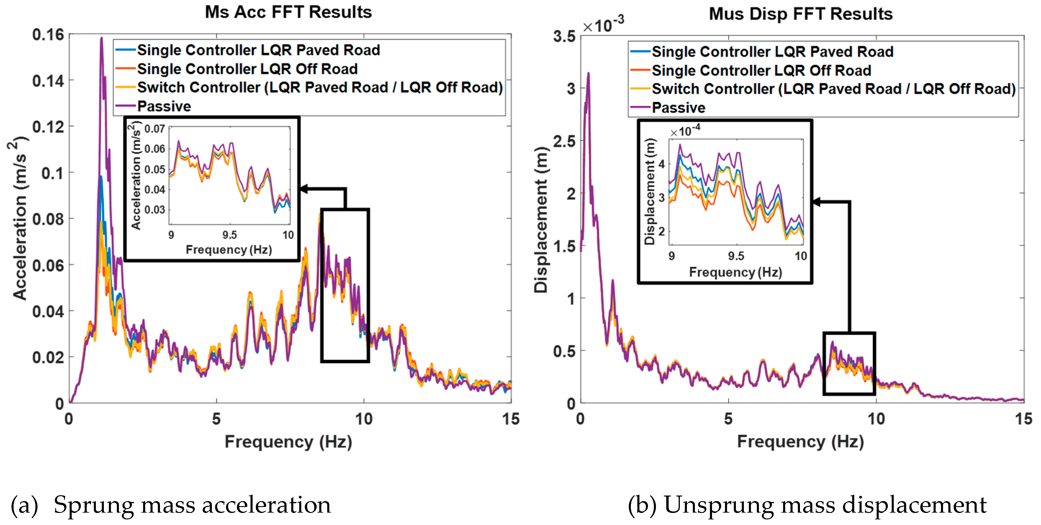
Figure 9. The vehicle speed was derived by fixing it at 40 km/h. The control results of switching controllers using Kalman filter-based LSTM classification logic, the results of each single controller (LQR_Paved Road, LQR_Off Road) without road classification logic, and the passive results without control input in frequency domain are shown
Figure 10-(a),(b).
Figure 10-(a) is the result of the acceleration of the vehicle body, and
Figure 10-(b) is the result of the displacement of the unsprung mass. With these results, it is possible to confirm the characteristics of the ride comfort and driving stability of each controller. As can be seen from (a) and (b) of
Figure 10, all results showed better performance than the passive result of not performing control. This means that the vehicle modeling and design of all controllers proceeded as intended. However, LQR_Paved Road occasionally exhibits inferiority to the passive system in unsprung mass displacement (
Figure 10-(b)), being 0.53% worse. Additionally, LQR_Off Road exhibits a 4.53% deterioration in sprung mass acceleration compared to the passive system, as shown in
Figure 10-(a). Accordingly, the switch control logic results showed plainly excellent overall vibration control results.
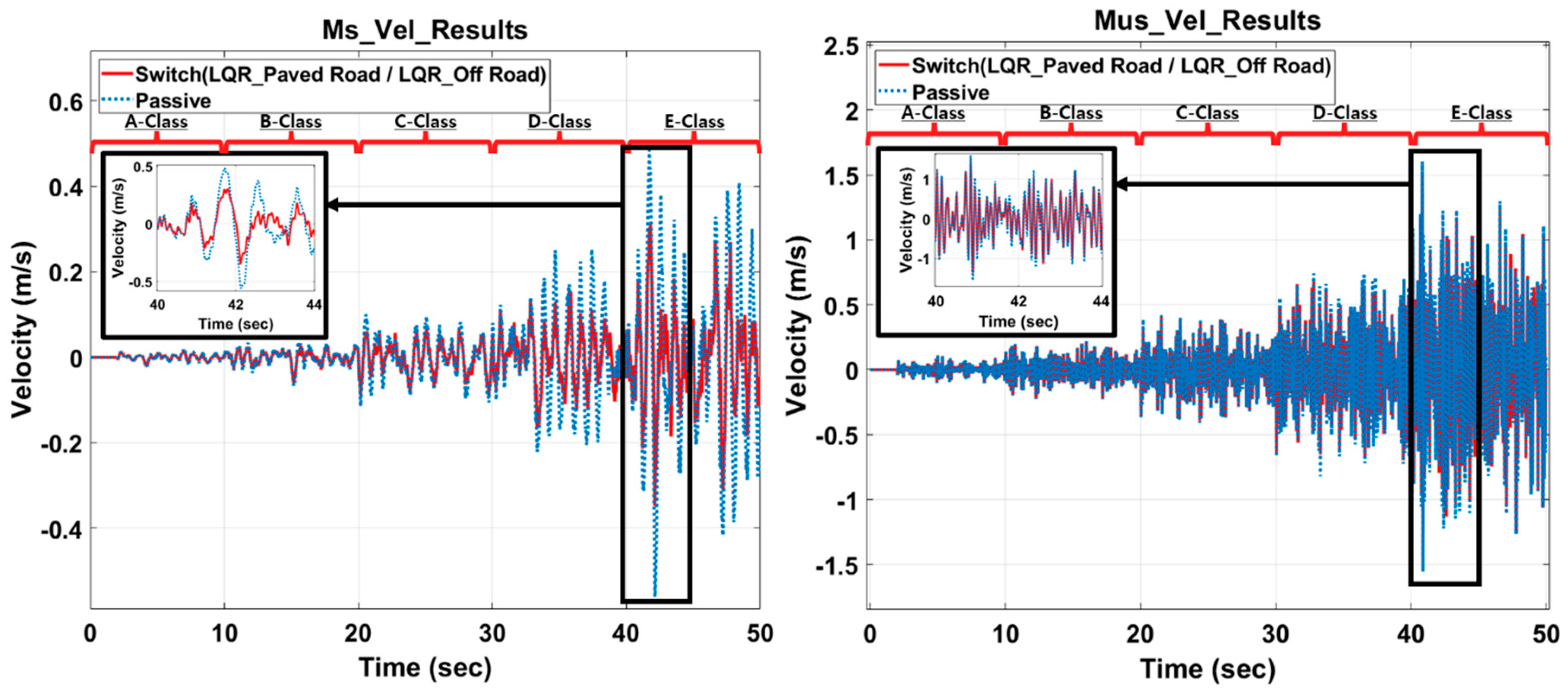
Based on the control characteristics of the LQR_Paved Road and LQR_Off Road controllers, an integrated control logic using switching logic and road type classification was designed to enhance the control performance. This encompassed both ride comfort and wheel motion. Typically, the LQR_Paved Road control is performed mainly for riding comfort, and the road type is classified using an LSTM artificial neural network. The Velocity results of sprung mass and unsprung mass for the control logic (Switch) are shown in
Figure 11-(a) and (b), respectively. As can be seen from the graph, excellent results were shown compared to Passive in most areas, and the effects of classification logic and control logic could be confirmed.
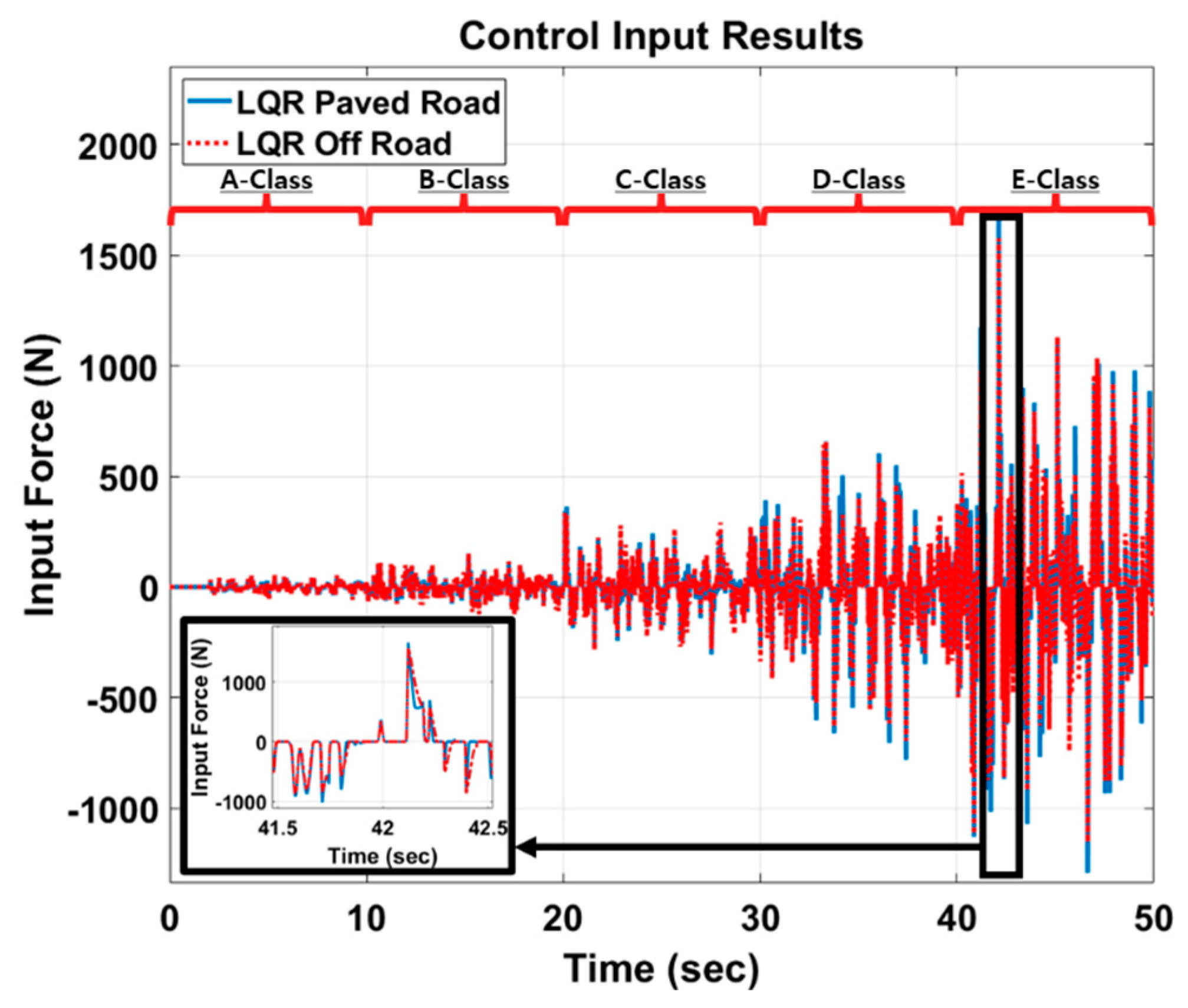
Figure 12 shows the result of the control input of each controller. Each controller generated a different input force according to each control characteristic. Furthermore, the force and control performance were not proportional. Nonetheless, as the input force was smaller, the energy efficiency was better because the control was performed with a smaller force. As a result, it was confirmed that the LQR_Paved Road controller had less energy consumption than the LQR_Off Road controller. For the Switch Control Logic, which performs control by combining these controllers, it displayed the median value of the input force from the two controllers. This indicates that the Switch Control Logic is an efficient and satisfying performance controller in terms of energy consumption.
Table 6 presents the results of each controller. Because ride comfort is related to the acceleration of the car body and tire deflection is related to the displacement of the wheel, all control results related to ride comfort and steering stability are presented. Therefore, when using a single controller, the overall ride comfort and wheel motion performance under various road conditions were not consistently favorable, depending on the characteristics of the controller. However, when the results of this study were applied with a switching logic that included a filter, positive outcomes were achieved for both the ride comfort and driving stability under all road conditions.
In terms of ride comfort, all controllers exhibited improvements compared to the passive system. Among them, the most notable outcome was observed with the LQR_Paved Road controller, showing a 5.8% reduction compared to the passive system. The Switch controller also demonstrated results closely resembling those of the LQR_Paved Road controller. Particularly noteworthy is the observation that the LQR_Off Road controller achieved a 3.08% reduction compared to the passive system. Therefore, in the context of ride comfort-oriented control, the Switch controller proved to be superior to the wheel-motion-centric controller (LQR_Off Road). In terms of vehicle stability, all controllers exhibited improvements compared to the passive system. Among them, the LQR_Off Road controller demonstrated a 6.25% enhancement, while the Switch controller showed a 4.17% improvement compared to the passive system. Furthermore, the vehicle stability results of the Switch controller surpassed those of the ride comfort-oriented controller, LQR_Paved Road. This signifies that the switch controller outperforms the other control logics and passive controller in all scenarios (ride comfort and vehicle stability). Specifically, for ride comfort on paved roads, it surpasses LQR_Off Road by 1.76%, and for wheel motion control on paved roads, it outperforms LQR_Paved Road by 2.13%. Therefore, the optimal switching control logic proposed in this study has been validated for enhancement of the robust vibration control performances across various road conditions.
