1. Introduction
The process of aging, degeneration, and disease-related damage in the central nervous system typically results in motor dysfunction, significantly affecting the daily activities of patients [1,2]. To restore all or partial of their motor functions, patients need to receive masses of rehabilitation therapy to induce neuroplasticity [3]. Achieving brain neuroplasticity from conventional rehabilitation therapy involves the coordination of multiple therapists, making it a labor-intensive and long-term process. Therefore, manual rehabilitation therapy presents limitations, including resource inadequacy, high financial investments, variability in training quality, and therapist burnout. To solve the issue, the development of robot-assisted therapy is emerging as a promising avenue for rehabilitation treatment. This approach offers highly repetitive, intensive, adaptable, and quantifiable rehabilitation therapies [4,5].
Recent studies in robotic therapy have indicated that the implementation of a progressive rehabilitation training model to promote patients’ motivation efforts can greatly restore the damaged central nervous system function in patients [6]. The patients’ active engagement is considered as one of the key factors contributing to the neural plasticity and motor recovery during the course of therapy. Consequently, researchers have proposed assist-as-needed (AAN) control strategy to better motivate patients’ active voluntary participation in upper limb rehabilitation therapy. The AAN strategy focuses on providing the minimal amount of robotic assistance necessary for a patient to complete a rehabilitation task, while a significant effort is required from the patient [7]. Deploying robotic assistance in accordance with AAN strategy come with some technical challenges. These challenges primarily involve effectively assessing patients' functional capabilities, accurately estimating the required motor support based on the patient's specific disability level or recovery progress, and dynamically adjusting the level of robot assistance in real time. These technical concerns are particularly complex in upper limb rehabilitation training, considering the diverse forms of exercises to complete various activities of daily living (ADL) training through occupational therapy (OT) for active rehabilitation training.
The assessment of patients' function abilities is predominantly categorized into two main approaches: the biomechanical model-based method [7,8] and the motor performance-based method [7,10–13]. In the context of biomechanical modeling, a skeletal muscle model is usually constructed and analyzed using biomechanical theories. This modeling process involves the identification of model parameters to quantitatively evaluate muscle forces and joint torques, thus contributing to the assessment of physical motor ability. For instance, Li Zhijun et al. [9] developed a reference musculoskeletal model of the human forearm’s joints. This model, driven by surface electromyography (sEMG), was utilized to calculate net torque and joint stiffness to match the operator’s motion behavior. Alternatively, a common approach for implementing the AAN strategy is through the utilization of the motor performance-based method. This method involves inferring the patient's assistance requirements based on their performance, which is then used to adapt the level of robotic assistance accordingly. Motion performance-based assessment methods can be broadly categorized into two main approaches. The first category relies on physical sensors to capture various signals, including commonly measured parameters such as joint position, velocity, and human-robot interaction forces. These signals are utilized to develop empirical formulas for the evaluation of motion performance or establish assessment criteria based on clinical medical scales. In [7], a new functional ability index (FAI) estimation algorithm in accordance with the clinical procedure was proposed for the estimation of subject’s motor ability in a movement task. The FAI evaluation algorithm was given by parameter equations including task completion time, angular position and velocity of the upper-limb joints. The position and velocity parameters were determined by the inertial measurement unit (IMU). Pehlivan et al. [10] applied a Kalman filter in conjunction with Lyapunov analysis to estimate the functional capabilities of subjects wearing the RiceWrist-S exoskeleton. The force estimator independently determined subject capability at each moment in time only based on position detection. The second category of motion performance assessment methods is centered around biological signals, such as electromyographic signals. These signals are harnessed to establish relationships that map to joint moments, facilitating the evaluation of an individual's physical exercise capacity. Tatsuya Teramae et al. [11] proposed using EMG signals to estimate the subject’s torque output. The relationship between the 16 EMG RMSs and the joint torque vector was modeled as a linear torque estimation model, with a neurofuzzy muscle-model matrix modifier. The neurofuzzy modifier output the coefficient for each weight of the muscle-model matrix to modify the weight matrix in real time based on the upper-limb posture of the user. This approach establishes a mapping relationship between EMG signals and joint torques through artificial intelligence algorithms such as support vector machines or neural networks. However, these methodologies do not delve into the intricacies of human biomechanical processes and fail to analyze the contributions of different muscles to various motions.
Building upon the techniques employed to assess a patient's motor functional ability, the determination of actual assistive torque and the specific implementation method of real-time control have emerged as focal points of research in AAN control. These research areas encompass several approaches, such as direct adjustment of assistive force/torque through force control methods [8,9,12], adaptive adjustment of impedance/admittance coefficients to achieving force/position interaction performance [7,13], and intelligent learning algorithms [14,15]. Shawgi Younis et al. [7] applied an adaptive inertia-related torque controller. This control strategy involves the design of an inner position loop nested within the outer torque feedback loop. The desired torque is computed based on the stiffness decay algorithm integrated with the value FAI, which either strengthens or relaxes the controller stiffness to enable modulation of the assistive torque. Carmichael et al. [8] developed an admittance control scheme to implement the AAN paradigm on the robot. The strength capability of the patient at their hand in the task space was calculated by an upper limb musculoskeletal model. A task model calculated the strength required for the ongoing task. This calculated task’s strength requirement was then compared with the operator’s strength capability to gauge the assistance force which was the input of the admittance controller. In [12], an upper limb mirror control strategy based on adaptive AAN was proposed. This adaptive AAN module combined the traditional impedance control with a method for assessing the movement state of the affected limb. It automatically adjusted the auxiliary force applied to the affected limb in real time to maximize the active torque of the affected limb. WANG et al. [13] presented an AAN control strategy for wrist rehabilitation robots. In this work, specific rules for evaluating the patient's abilities were established, and the patient's functional capabilities were assessed in accordance with these predefined criteria. The controller was designed based on impedance control theory and dynamics model. It dynamically adjusted the impedance coefficients in response to both the reference trajectory and the assessment of the affected limb's kinematic ability, enabling precise and on-demand modulation of the total output torque of the robot.
Under the environment of rapid development of artificial intelligence, researchers have increasingly focused on intelligent control methods with inherent learning capabilities for upper limb rehabilitation exoskeleton robots. For example, neural network control methods, reinforcement learning control methods, etc. In [14], a greedy AAN (GAAN) controller was designed for the upper limb rehabilitation training of neurologically impaired subjects. The GAAN control paradigm included a baseline controller and a Gaussian radial basis function (RBF) network. This RBF network played a pivotal role in modeling the functional capabilities of the subjects. The weight vectors of RBF networks evaluating subjects’ impairment level were updated according to a greedy strategy, so that the maximum force provided by the subjects is gradually learned over time.
The aforementioned forms of adaptive AAN control primarily focus on assessing the patient's motor functional ability by the affected limb. In the process of formulating task-specific assistive guidelines, the requisite torque for task completion has traditionally been ascertained through either modeling the rehabilitation task or integrating interactive torques of the affected limb into the robot's dynamic model. These methods are subjective and experience-based, representing a form of artificially set expectations. As a result, AAN control, in which the designer determines the desired outcome, tends to diverge from the patient expectations and is less adaptable to the diverse requirements of individual patients.
In view of the above problems, this paper introduces a novel AAN control method based on the patient's own motor performance of the healthy limb. The study is conducted on a self-developed pneumatic upper limb rehabilitation robot. Employing the AAN control strategy, this system facilitates collaborative rehabilitation training tasks between the patient and the robot. It achieves this by leveraging both the active torque generated by the patient and the torque output from the robotic system. To implement AAN control, myoelectric signals and human-robot interaction forces are collected during the patient's movement to assess their motor ability. This assessment involves a comparison and analysis with the motor performance of the healthy limb to accurately identify deficiencies in the affected limb motor abilities when performing the same movements. Subsequently, the robot's rehabilitation training trajectory and assisting force are dynamically adjusted based on the actual motor performance of the affected limb. The significance of this study lies in utilizing the patient's healthy limb performance as a benchmark, comparing it with the affected limb's motor capabilities to determine the robot's assisting torque. Additionally, the stiffness information of the healthy limb is utilized as a criterion for the necessary motor ability to complete the task, as stiffness reflects the force/position interaction characteristics of the human body during the rehabilitation process. This method makes robot assisted rehabilitation training more in line with the patient's own characteristics and hand habits. Moreover, the rehabilitation robot's motions adjusted in time according to the flexibility of the human healthy limb are more natural. These refinements significantly enhance the comfort experienced by the affected limb.
2. Upper Limb Rehabilitation End-Effector Robot
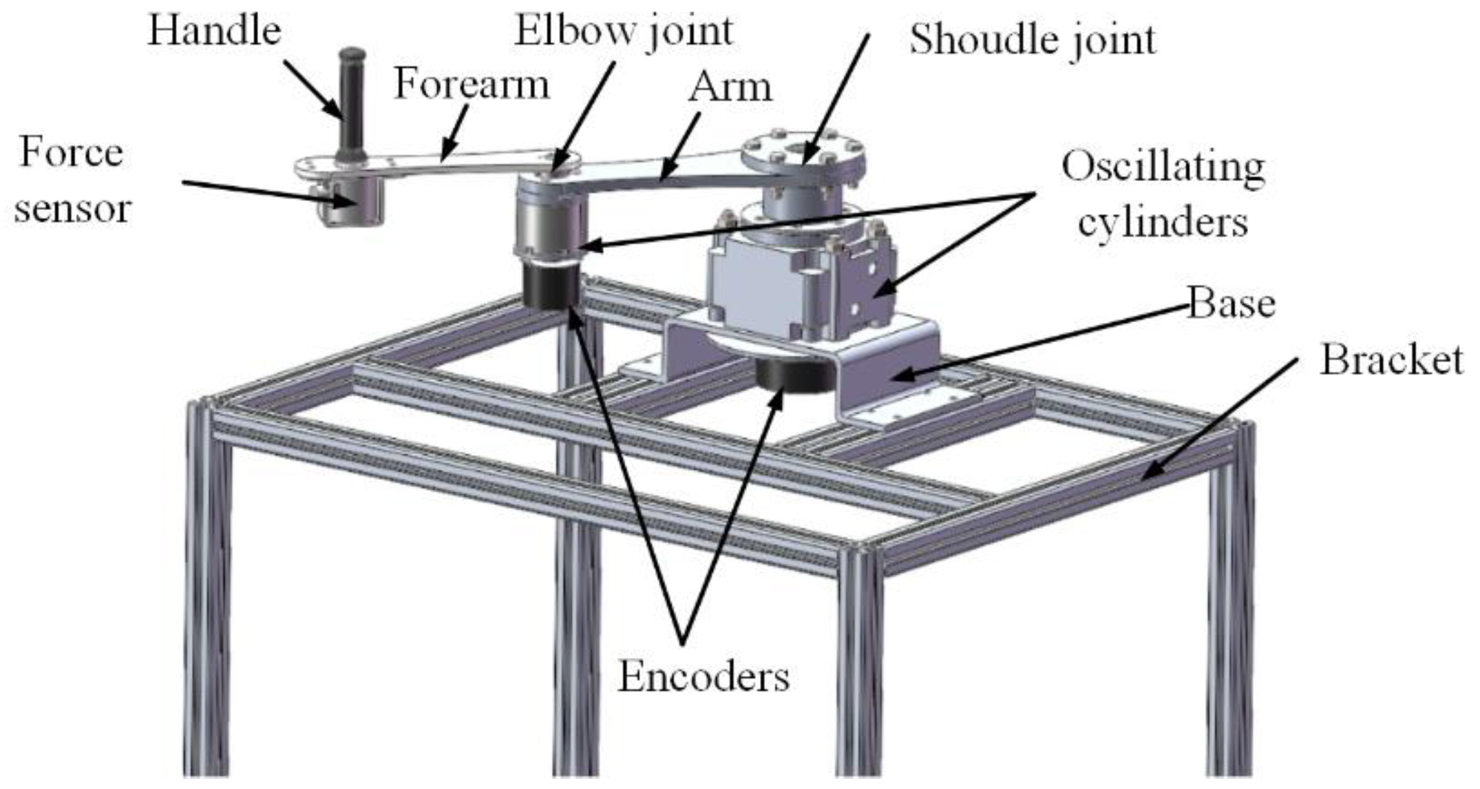
The upper limb rehabilitation training robot developed by us is a pneumatic-driven end-effector robot which drags the patient to complete the rehabilitation training when he grasps the handle. This robot is composed of an arm linkage, a forearm linkage, two joint components, a handle, and a base. The three-dimensional structure of the robot is shown in
Figure 1, and the mechanical structural parameters of the robot are shown in
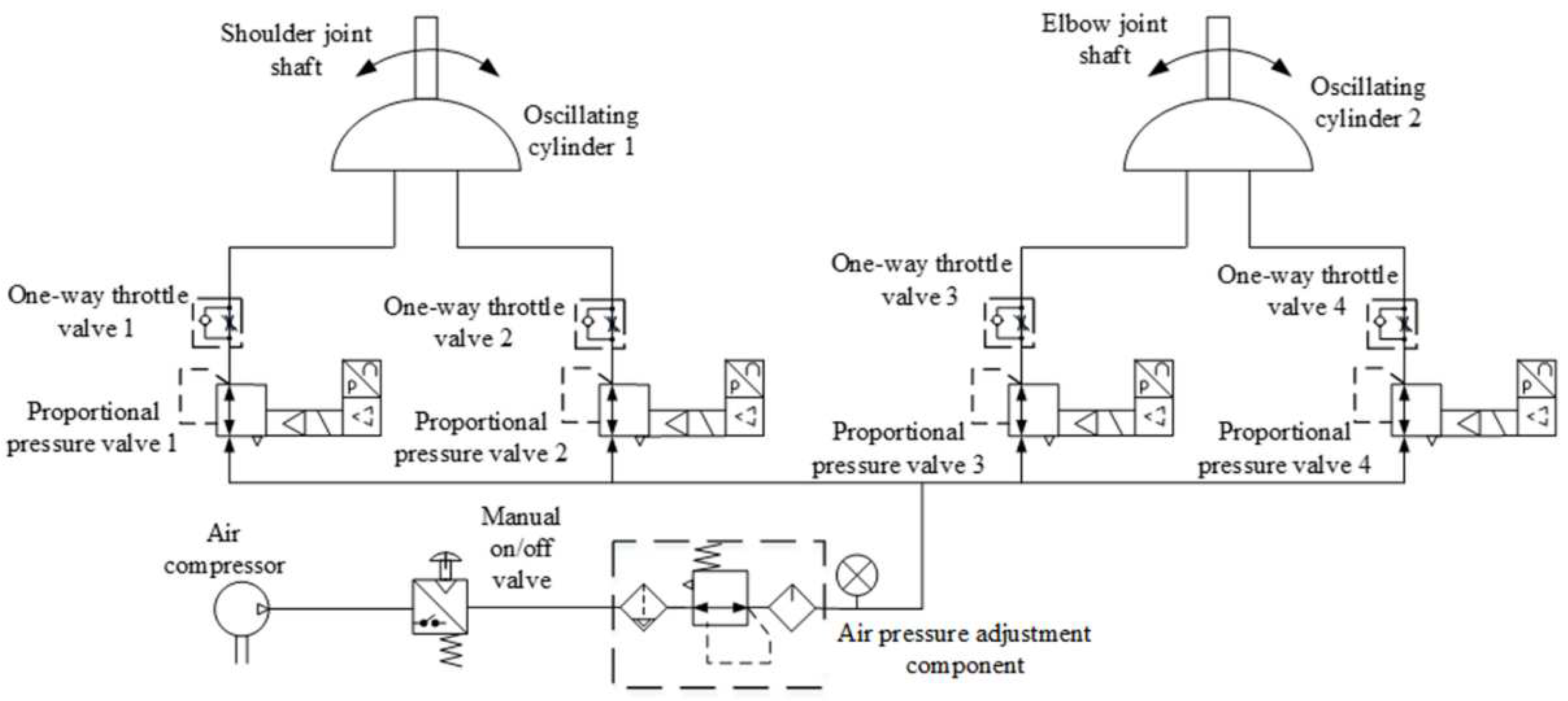
Table 1. Differing from the common form that servo motors drive the joints through the reducer, the robot's joints are directly driven by oscillating cylinders, possessing reverse driving capability and exhibiting a certain level of compliance due to pneumatic driving. Each joint axis is equipped with incremental encoders to detect joint rotation angles, while a three-dimensional force sensor is mounted at the end handle of the robot to measure human-robot interaction forces. Real-time detection of both sensors enables the collection and feedback of motion and force information. A joint oscillating cylinder is controlled by a pair of proportional pressure valves, with one side providing driving force and the other side providing back pressure to enhance start-up steadiness and motion stability. The pneumatic drive system for the robot joints is illustrated in
Figure 2. By adjusting the control voltage of the proportional pressure valves through a control strategy, the swing angle and output torque of the oscillating cylinder can be modified to facilitate trajectory tracking control for rehabilitation and dynamic adjustment of assisting forces. Proportional pressure valves, the gas supply system, and controllers are discreetly installed beneath the base bracket.
3. Personalized Assist-as-Needed Control Strategy
An adaptive AAN control strategy is proposed in this research. With the control strategy, the robot adjusts the assistance needs of the affected limb by comparing it with the movement characteristics of the healthy limb.
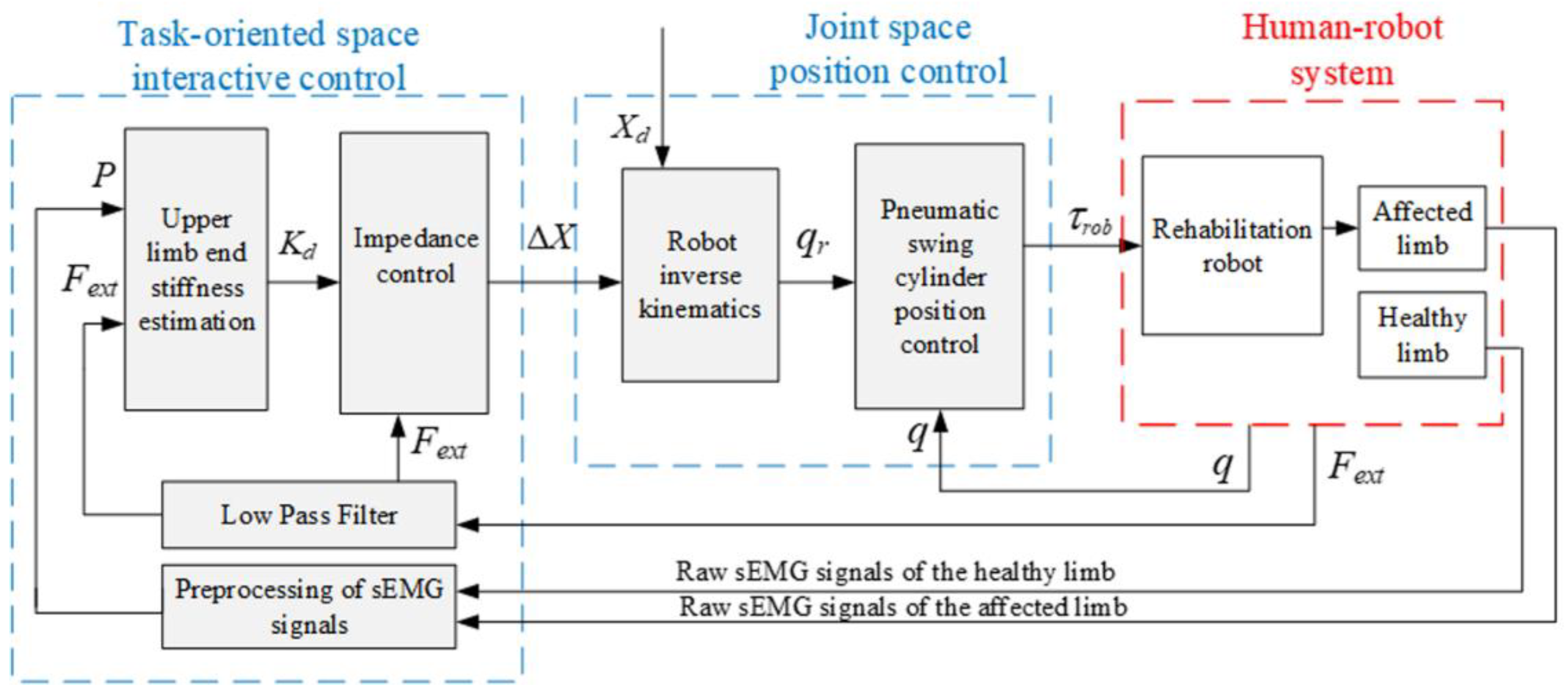
The end-effector robot interacts physically with the patient's hand, so rehabilitation tasks are planned in the task-oriented space, and the robot is controlled in the joint space. As shown in
Figure 3, the strategy comprises an interactive control module in the task-oriented space based on the quantitative evaluation of motion needs and an inner loop position control module for the pneumatic swing cylinder in the joint space. In the position control module, the planned trajectory
Xd and the adjusted value Δ
X are converted into the desired joint angle
qr through inverse kinematics, and the robot joints angles
q are controlled according to
qr through a position controller. A variable impedance control strategy based on patient upper limb end stiffness regulation is constructed in the interaction control module of the outer loop. For this strategy, the end stiffness of the healthy limb is estimated based on the vector
P of muscular activities obtained from preprocessed sEMG signals, and then quantified as the stiffness value
Kd of the impedance controller by comparing with the motor performance of the affected limb. Then the task trajectory is adjusted according to the human-robot contact force
Fext between the affected limb and the robot, aiming to provide AAN rehabilitation motion. The AAN assessment is grounded in the stiffness characteristics of the patient's own healthy limb when performing the interaction task. It better aligns with the force/position dynamic adjustment characteristics exhibited during the patient's daily motions, thereby providing individualized advantages for rehabilitation exercises.
3.1. Interactive control algorithms and stiffness mapping criteria
The impedance control strategy is a compelling method for effectively facilitating robot-environment interaction, employing an impedance model to articulate the dynamic relationship between force and position [16,17]. On the basis of the inner-loop position control, the outer loop employs a position-based impedance control strategy for interactive control, as illustrated in
Figure 3.
The impedance model of the robot in Cartesian space (i.e. the task-oriented space) is equivalent to a second-order dynamical system [18]:
where
,
and
are the mass, damping and stiffness coefficient matrix, respectively;
is the position correction in the task-oriented space;
is the external force applied to the robot.
The variation of impedance parameters will have varying degrees of impact on the effectiveness of robots in completing tasks [19]. In order to facilitate an effective rehabilitation process, the robotic systems should exploit the patient’s physical capabilities and offer proper stiffness range to provide assistance as needed in training processes. Consequently, an impedance control strategy with variable parameters is proposed in this study. This strategy takes the stiffness of the healthy limb and the affected limb as reference and can dynamically adjust impedance control parameters according to the patient's movement performance, so that the patient's rehabilitation needs can be met and the rehabilitation effectiveness can be enhanced.
The impedance parameters of the human upper limb are mapped to the impedance controller by designing a mapping criterion. As a result, the rehabilitation training robot, which mimics the motion characteristics of the patient's healthy limb, drives the affected limb. This alignment ensures that the rehabilitation training motion is more consistent with the individual's force generation habit. The parameter mapping criteria are outlined as follows:
where
is the endpoint stiffness of the healthy limb for normal motion, estimated based on sEMG;
is the endpoint stiffness of the affected limb for the same motion, estimated based on sEMG;
is the damping ratio, which is selected to be 0.8 according to the stability requirements in pneumatic robots.
The interactive force between the affected limb and the robot adjusts the end-effector trajectory. The corrected trajectory is:
where
is the desired rehabilitation motion trajectory.
The robot joints are actuated by the swing cylinders, which need to be controlled in the joint space. As a consequence, the external torque,
, can be obtained from the end interaction force
using the force Jacobian matrix
:
The force Jacobi matrix
of the 2-degree-of-freedom robot is represented as follows:
where
and
denote the joint angles of the upper arm and forearm, respectively;
L1 and
L2 represent the lengths of the linkage segments corresponding to the robot's upper arm and forearm.
The dynamical model of the robot in the joint space can be written as follow:
with
denoting the joint torque vectors output by the swing cylinder.
For the two-link planar robot shown in
Figure 1, the dynamical equation coefficients in Equation (6) are given as follows:
The mass matrix is composed of all those terms which multiply
and is a function of
. Therefore, we have
with
The velocity term, Coriolis/centrifugal matrix, contains all those terms that have any dependence on joint velocity. Thus, we obtain
with
In Equation (7) and Equation (8), m1, m2 are the concentrated masses of the robot's upper arm and forearm.
3.2. Position control algorithms in the joint space
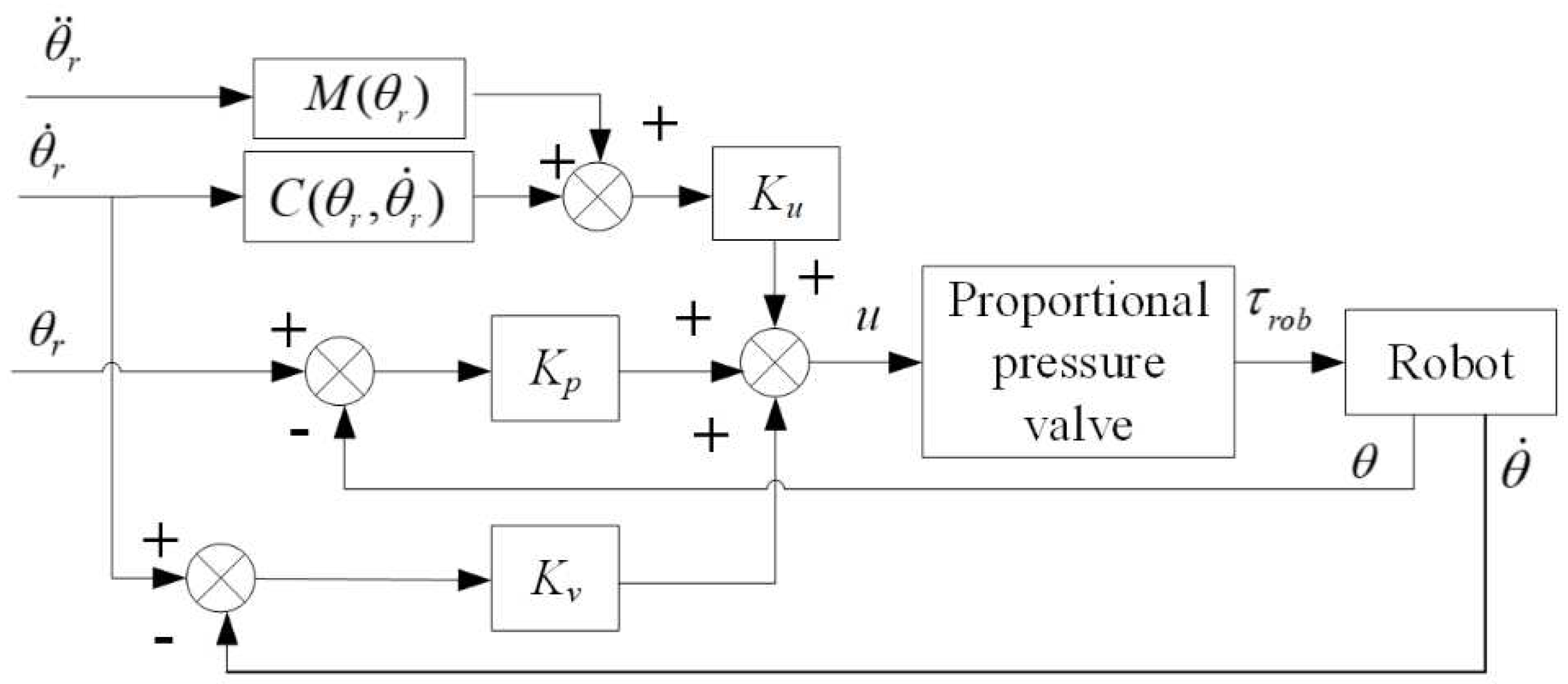
The position control module employs the PD (Proportional-Derivative) control strategy with dynamic terms feedforward. To address the characteristics of the pneumatic proportional system [20], PD control is employed to increase system damping, thereby enhancing system stability. Given the low-speed crawling issue in the swing cylinder and the joint motion coupling characteristics of the robot, dynamic terms feedforward control is introduced to compensate for torque, thereby improving the dynamic response of the pneumatic system and enhancing the robot's position control accuracy. The schematic diagram of the position control strategy is shown in
Figure 4.
The PD control with dynamic terms feedforward algorithm is outlined as follows:
where
is the desired joint trajectory;
is the actual joint trajectory;
is the output voltage of the PD control;
is the control voltage for the proportional pressure valve;
is the proportional coefficient matrix of the dynamic terms feedforward control;
and
are the proportional and differential coefficient matrices of the PD control, respectively.
The control voltage of proportional pressure valve is linearly related to the output torque of the swing cylinder installed on the robot to drive joints. The output torque
is calculated as Equation (10), and the proportional coefficient
Kτ can be determined experimentally.
4. Human Arm Endpoint Stiffness Estimation Method
The mechanical characteristics of the human arm reflect the patient's movement ability in the motion interaction of the end-effector rehabilitation robot dragging the patient. One way to quantify the performance of the interaction between the limb and the robot in rehabilitation tasks is through the estimation of the endpoint stiffness. The stiffness can be modified via co-contraction of muscles involve in task execution [21]. Therefore, an upper limb endpoint stiffness estimation model based on sEMG signals is constructed to map between muscular activities and resulting arm endpoint force and stiffness. And then the parameters within the model are identified by the small perturbation method.
4.1. Endpoint Stiffness Estimation Modeling
When humans perform tasks, the force required for task completion is generated by altering the activation pattern of individual muscles, and the stiffness for task completion is regulated through the co-contraction of muscle groups, with both processes operating independently. Specifically, the resulting modifications in force and impedance can be regarded as the effects of internal force regulation exerted by group of extensor and flexor muscles. Agonist–antagonist muscle co-contractions affect and modify the stiffness of the arm endpoint. In the equilibrium position, the counterbalance of flexor and extensor muscle forces results in no force variation and joint rotation, but the co-contraction of the muscles leads to an increase in stiffness. When maintaining posture amidst mechanical perturbation, changes in force and impedance exhibit a linear relationship with the level of muscle activation [22,23]. The mapping between muscular activities and resulting arm endpoint force and stiffness in Cartesian coordination can be compactly described by [24]
where
and
represent the endpoint force and stiffness vectors,respectively;
is the EMG-to-force map matrix;
is the EMG-to-stiffness map matrix;
P is the vector of muscular activities, as obtained from preprocessing EMG signals from electrodes applied on each muscle, and
K0 is the intrinsic stiffness in relaxed conditions.
The robot pulls the patient to move in the plane, and thus
and
are both 2-dimensional vectors. The EMG-to-force map matrix
is defined as
where
and
are the force-map coefficients of the
-th agonist muscle in the X and Y directions;
and
are the force-map coefficients of the
-th antagonist muscle in the X and Y directions.
The identification of the EMG-to-force map matrix is relatively easily done by precise measurements of endpoint force and the EMG signals of the individual muscles, while it is more challenging to identify the EMG-to-stiffness map matrix matrix by the EMG signals due to the co-contraction of muscle groups. To solve the problem, Arash Ajoudani [21] proposed an algorithm for estimating the human arm stiffness using the null-space which contains information about the co-contraction component of stiffness generation.
A decomposition of the space of muscular activations
P as the direct sum of a force-generating subspace
and the force-map null space
, i.e.
Let
NF denote a basis matrix for the kernel of
TF, and it is written as
where
is the right-inverse matrix of
TF, i.e.
.
Consequently, the null-space component
can be expressed as
The model for Cartesian stiffness regulation through co-contraction is formulated as
where
is a mapping from the force-map null space
(the set of muscle activations that do not change endpoint force) to stiffness variations.
From the above algorithms, it can be seen that the established estimation model for endpoint stiffness based on force-map null space vectors describes the relationship between muscle co-contraction and stiffness.
4.2. Parameter Identification of Stiffness Estimation Model
4.2.1. Identification of EMG-to-force map matrix
The relationship between the endpoint force and the muscular activities vector can be derived from Equation (11) as
The dataset {, P} is constructed by acquiring multiple sets of EMG signals from dominant muscles and the endpoint forces during the completion of rehabilitation training tasks. Then the identification of the EMG-to-force map matrix can be accomplished by utilizing the projected gradient descent algorithm for the linear equation (17).
For the end-effector rehabilitation robot, dragging the patient's upper limb in-plane to accomplish rehabilitation, we estimate by combining the endpoint force vectors in the horizontal plane with the measured activities of four involved muscles. The endpoint forces in the horizontal plane, = , are detected by a 3-axis force sensor connected to a handle equipped at the endpoint of the robot arm. The analogue sEMG signals from the dominant muscles associated with shoulder and elbow joint motions are collected and amplified separately utilizing an EMG signal detector. Four dominant muscles acting on elbow and shoulder joints [25] are chosen as the sources of sEMG recordings, including two flexors: Biceps long head (BILH) and Deltoid clavicular part (DELC), and two extensors: Triceps lateral head (TRIA) and Deltoid scapular part (DELS). Due to the raw surface electromyographic (sEMG) signals directly acquired through electrode pads contain information about the activity of motor units on muscle fibers, along with the introduction of some noise signals, a preprocessing algorithm is employed to extract the envelope amplitude of the raw sEMG signals. The preprocessing algorithm includes procedures such as linear noise removal, Butterworth bandpass filtering, and root mean square envelope calculation.
4.2.2. Identification of EMG-to-stiffness map matrix
From equations (14) - (16), it can be inferred that the kernel matrix NF is initially obtained from the identified EMG-to-force map matrix . Subsequently, the identification of the EMG-to-stiffness map matrix for the linear equation (16) can be achieved through the application of the projection gradient descent algorithm.
During the identification process, the participant grasps the handle at the robot's end-effector and generates random perturbation forces of a certain peak value in the X and Y directions by varying degrees of muscle contraction, respectively, thereby the process creating a sufficient dataset. This interactive process is described by the Cartesian space impedance model:
where
is the human-robot interaction force,
,
and
are the mass, damping and stiffness matrices of the endpoint of the upper limb, respectively;
is the endpoint position, and
is the initial position point.
During the experiment, it is necessary for the testers to perform contraction motions at varying levels of muscle activity. This can be referenced using the co-contraction index
TCI as a criterion [25], with the definition as follows:
where
and
are the contraction indices corresponding to the forces acting in the X and Y directions at the end-effector in the plane. They can be solved by the identified EMG-to-force map matrix
and the muscular activities vector
P:
The co-contraction index (TCI) needs to be normalized for different patients, with
TCImin representing muscle relaxation and
TCImax representing full muscle contraction. The muscle contraction rate
is defined based on the normalized
TCI index:
When the muscles are in a relaxed state,
= 0, as indicated by equation (18), by applying a small mechanical perturbation to the endpoint of the human arm by the robot, the initial intrinsic impedance parameters (
,
,
) can be obtained based on the measured restoring force and position deviation. When the patient has active motions, the muscles are in a certain contraction state exerting force to the robot. The endpoint stiffness of the human upper limb
is calculated by Equation (18) at this time. let
, and then the formula (16) is rewritten as
For the linear equation (22), the endpoint stiffness mapping matrix identification can also be accomplished by employing the projected gradient descent algorithm.
5. Experiments and Results Analysis
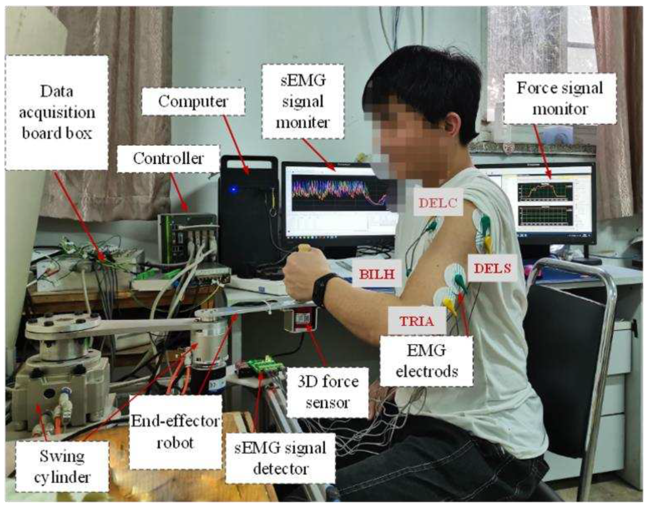
In order to evaluate the effectiveness of the proposed control method, experiments have been carried out. The experimental system primarily consists of a two-degree-of-freedom end-effector rehabilitation training robot prototype driven by pneumatic swing cylinder, a computer, a controller, data acquisition boards, a three-dimensional force sensor, and a sEMG signal acquisition device, as depicted in
Figure 5.
5.1. Parameter Identification and Stiffness Estimation Experiment
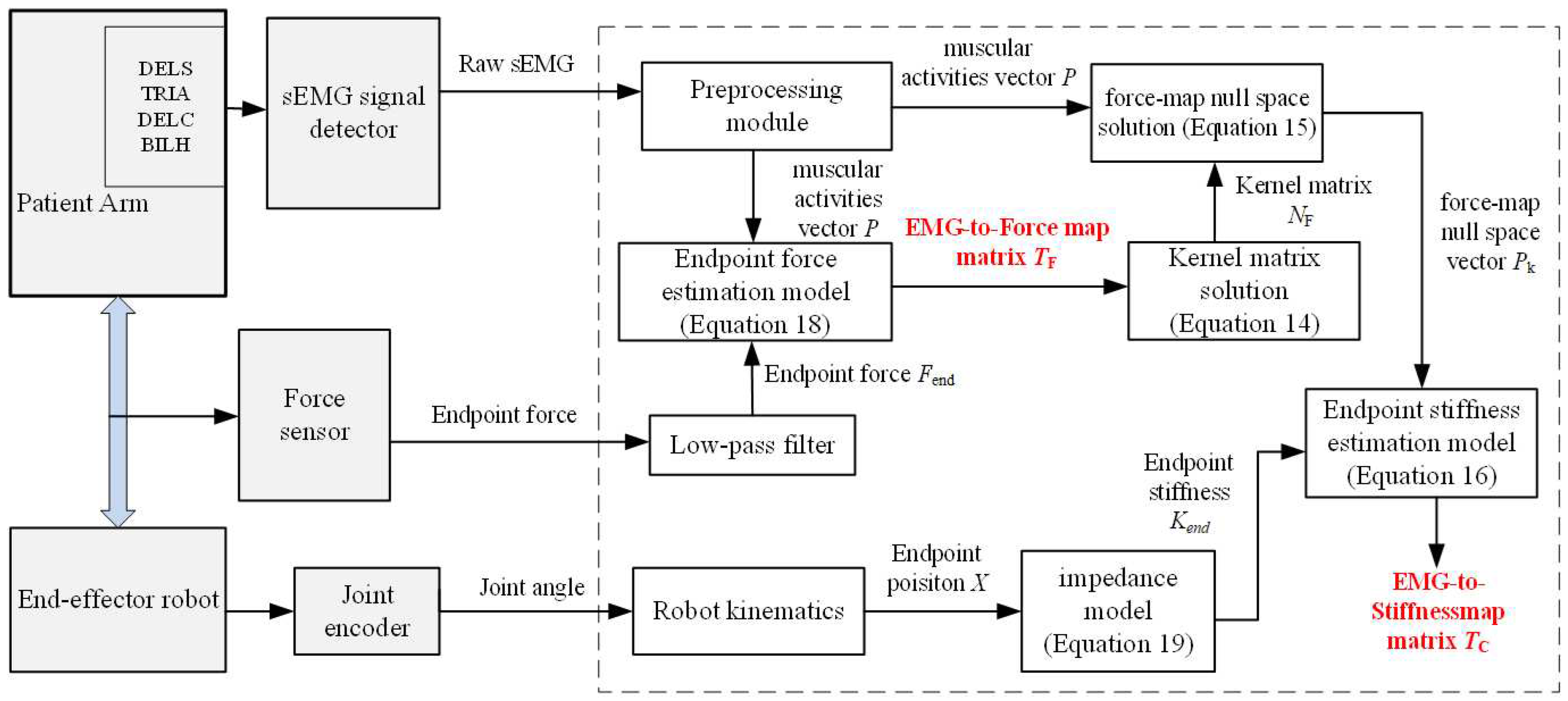
Based on the stiffness estimation model, the experimental and computational procedures are designed according to the parameter identification method explained in part IV, as illustrated in
Figure 6.
Initially, the identification of the EMG-to-force map matrix
was completed. The robot was in a no-drive mode and serves only as a support for the force sensors. The test subject sat upright, naturally placing the upper arm, and tightly gripped the robot handle by the hand. The participant, with electrode sheets affixed to four muscles of the healthy limb, generated specified force in the X and Y directions, respectively. Six sets of force data and twelve sets of sEMG data (across 4 channels) were obtained by measuring three times in each direction. Using these data, the identification of
was achieved through the application of the projected gradient descent algorithm, and the results were as follows.
Based on the identified
, the kernel matrix
was calculated by Equation (14).
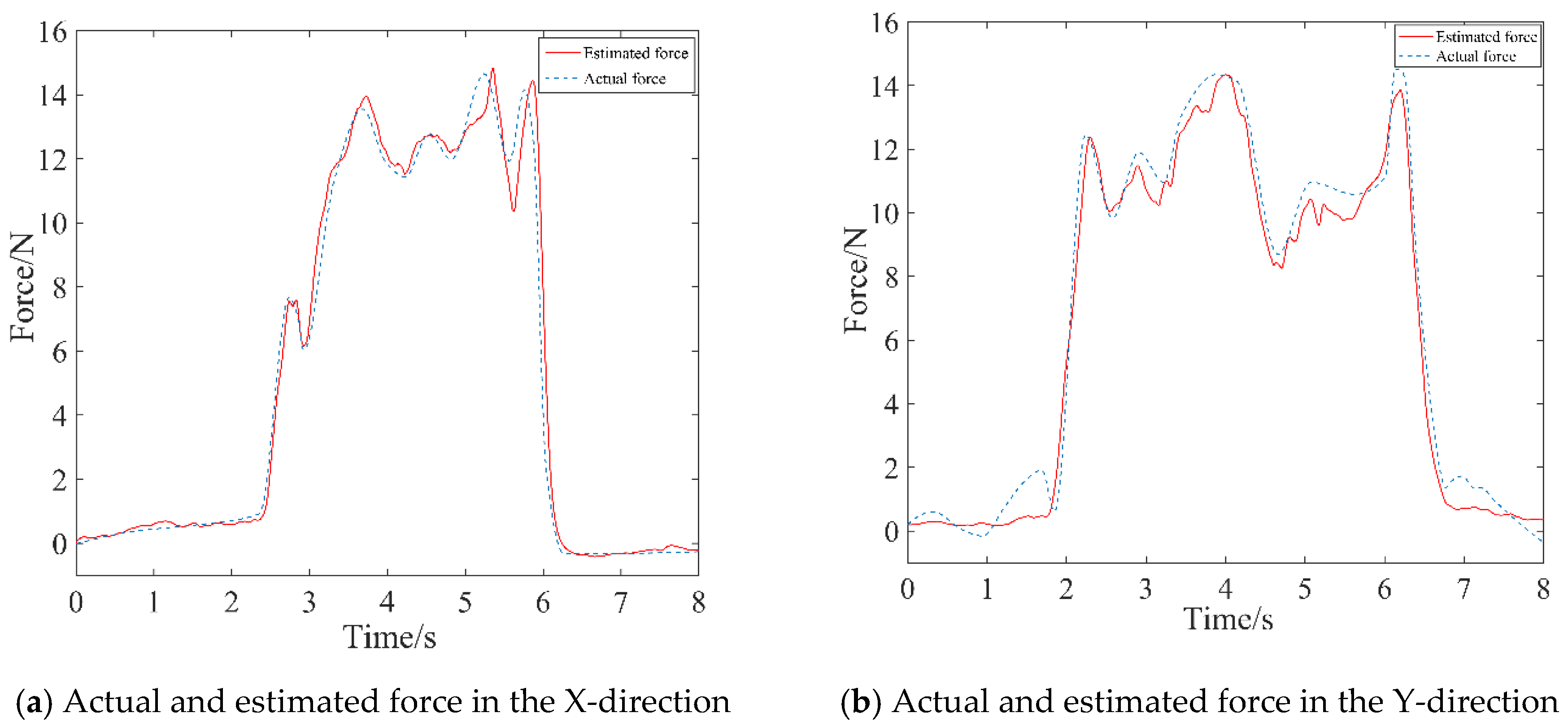
The estimated force was calculated by Equation (17), which was then compared to the actual force measured by the force sensor, as depicted by the curve in
Figure 7. Consequently, the proposed identification method was demonstrated, providing a better representation of the mapping relationship between sEMG signals and endpoint forces.
In the following phase, the upper limb end-effector rehabilitation robot transitioned into an active control mode. The participant gripped the handle at the robot's endpoint, generating random perturbations with specific peaks in the X and Y directions. The intrinsic impedance parameters (
,
,
) of the upper limb endpoint were calculated by Equation (18) in relaxed state of the muscles in the healthy limb, specifically at a contraction rate
= 0. These parameters were detailed in
Table 2.
The human-robot interaction force and positional deviation were detected again under the muscle contraction state of the healthy limb, and the endpoint stiffness
of the upper limb was calculated by Equation (18). Finally, the endpoint stiffness mapping matrix was identified, and the results were as follows.
5.2. Assist-as-Needed Control Experiment
Within the safe working space of the experimental prototype, the rehabilitation training experiments with AAN control were conducted by planning circular motion trajectory in Cartesian space. Multiple healthy individuals participated in the experiments, simulating different degrees of motion impairments. The robot pulled their arms to perform circular training in the plane.
Firstly, the effectiveness of the inner-loop position controller was verified through passive rehabilitation training experiments. The passive rehabilitation training mode referred to training that is completely driven by robots when the affected limb was in a flaccid state. Due to the lack of human-machine contact force during this training process, the interaction control of the outer loop was not effective, and the robot joint motion was only controlled by the position controller to track the planned circular training trajectory. The robot's joints were driven by the swing cylinders which were controlled by proportional pressure valves. Precision in pneumatic joints’ position control was ensured through the PD control with dynamic terms feedforward strategy as mentioned in
Section 3. The stable pressure provided by the pump during operation was 0.6 MPa, and the coefficient
Kτ of the proportional pressure valve was experimentally determined to be 0.06. The control parameters were listed in
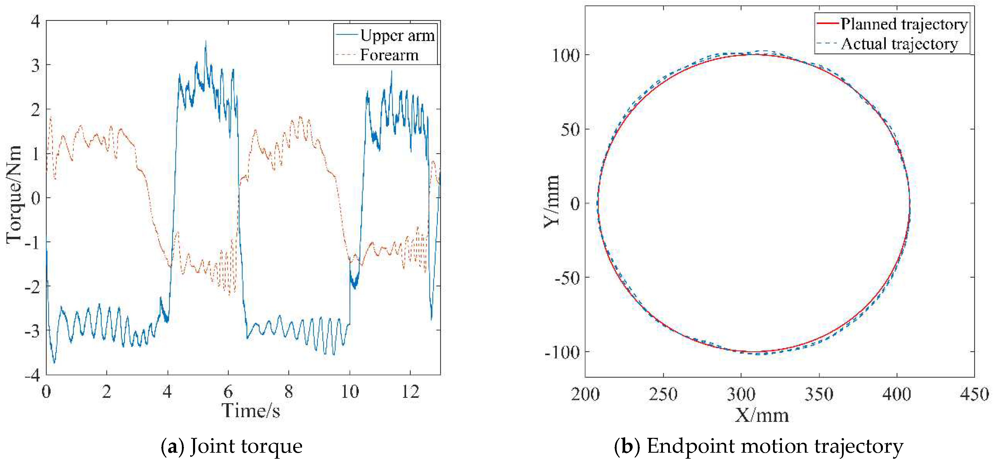
Table 3. The motion trajectory at the robot's endpoint and the joint torque curves were depicted in
Figure 8.
During passive rehabilitation training, the robot provided the patient with the maximum assistive torque, given that the affected limb had no active participation ability. As shown in
Figure 8(a), the joint torque provided by the robot upper arm is about 3 N m, and the joint torque provided by the forearm is about 1.5 N m. At the same time, the robot drove the affected limb according to the planned trajectory with a small error, as shown in
Figure 8 (a). The average absolute position errors in X-axis and Y-axis relative to the planning trajectory are 2.13 mm and 3.05 mm, respectively, through statistical calculations. The position accuracy meets the needs of rehabilitation training, thus verifying the effectiveness of the design of the position control strategy.
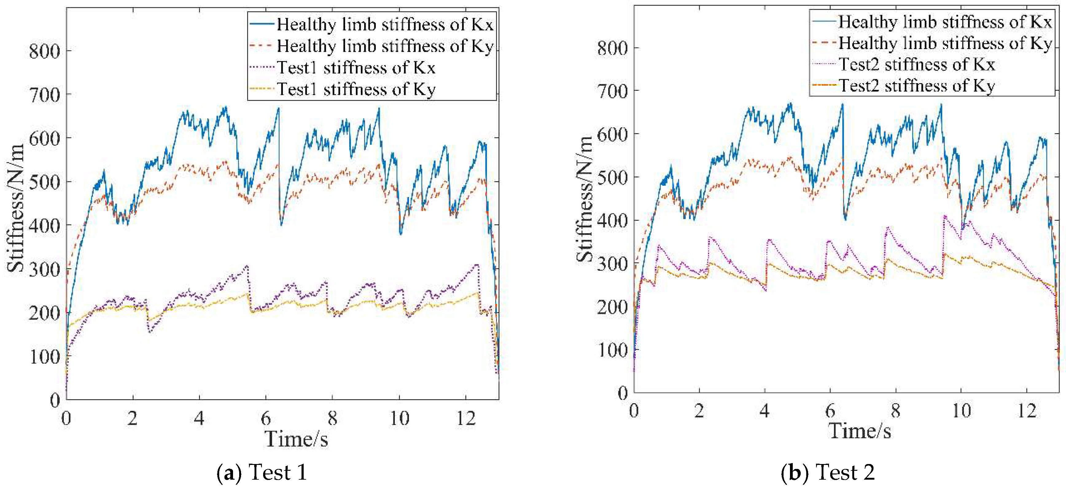
Active rehabilitation training was employed during stages when the affected limb possessed a certain level of motion capability, utilizing the AAN control strategy proposed in this study. In the AAN control experiments, the tester interacted with the robot by varying muscle contraction intensity and output force to imitate affected limbs with different motor abilities. These were referred to as Test 1 and Test 2 and labeled in the experimental curves. EMG signals from both the healthy and affected limbs were collected. Then the estimated stiffnesses were obtained by utilizing the stiffness estimation algorithm, and the curves were shown in
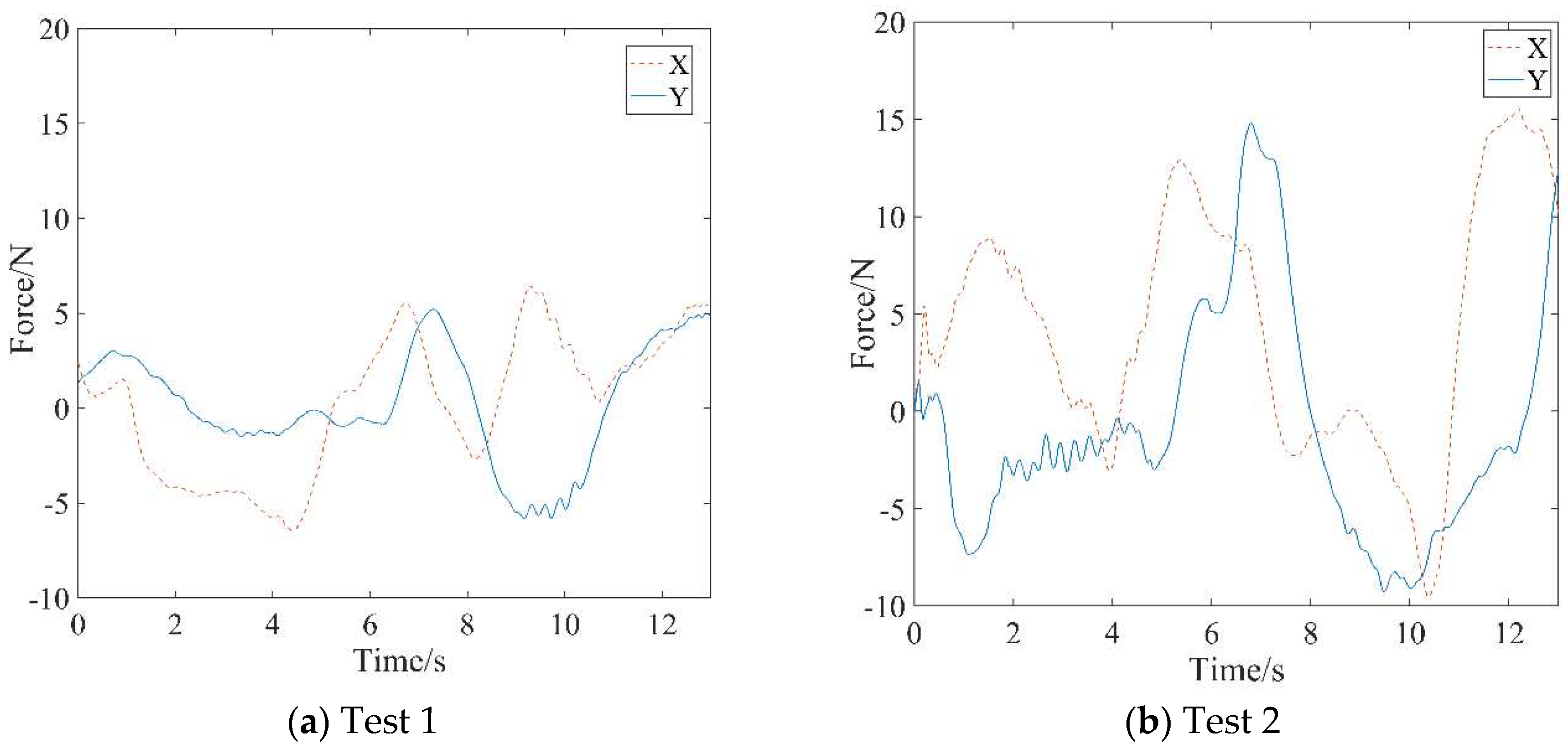
Figure 9. The forces between the affected limb and the robot were synchronously acquired, as depicted in
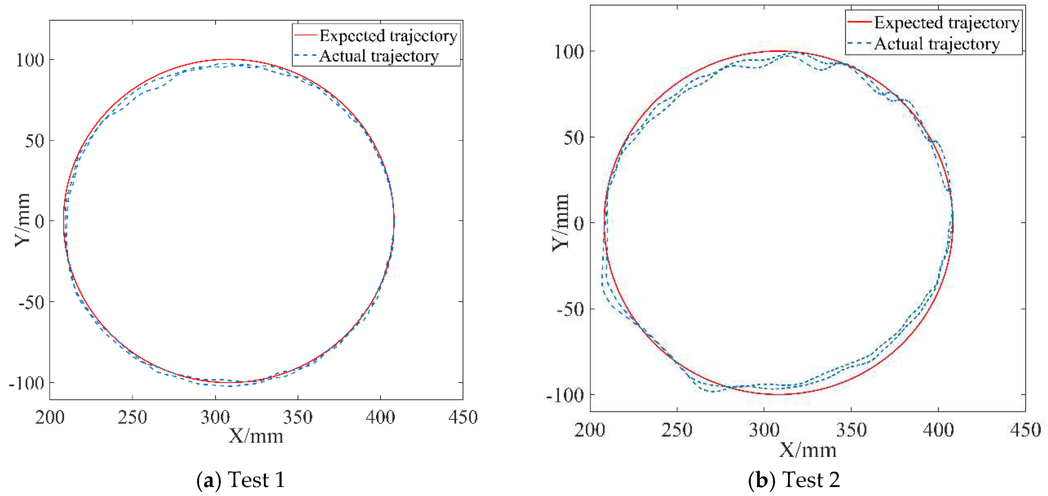
Figure 10. The robot endpoint motion trajectory under AAN control was illustrated in
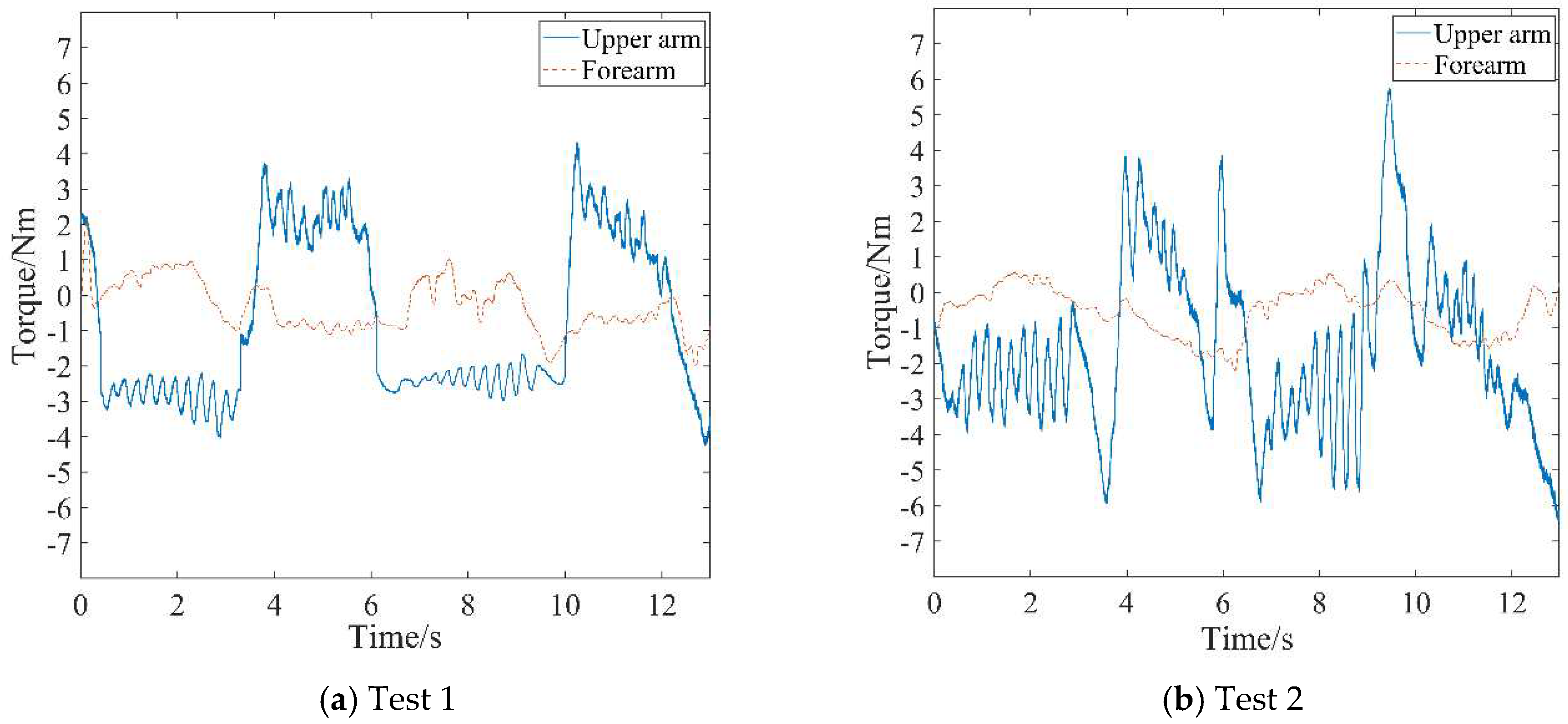
Figure 11, while the robot joint torques were presented in
Figure 12.
5.3. Discussion
Upon observing the aforementioned test data in
Figure 9 to 12, the AAN characteristics of the robot in active rehabilitation training are analyzed and discussed in detail as follows:
(1) As shown in
Figure 9, the mean value for the endpoint stiffness in the X-direction of the healthy limb is approximately 550 N/m, and the mean value for the endpoint stiffness in the Y-direction is about 450 N/m. The endpoint stiffness values of both Test 1 and Test 2 are lower than that of the healthy limb, with Test 1 having a lower stiffness than Test 2. Therefore, Test 1 is used to simulate the more severely affected limb, while Test 2 is used to simulate the less severely affected limb. Testers couldn't maintain entirely the same muscle contraction intensity during motion, so the measured stiffness has the characteristics of fluctuating at a constant level. Meanwhile, the stiffness in the X-direction is slightly greater than that in the Y-direction when completing the task of drawing a circle. This observation reflects the stiffness characteristics of human motion in different directions during the task, indicating good consistency of the algorithm's recognition.
(2) The real-time changes in endpoint forces detected by the force sensor mounted at the handle's endpoint for the two tests are illustrated in
Figure 10. A comparison reveals that the variation trends of endpoint forces in the two experiments are similar. Nevertheless, the endpoint force in Test 1 is significantly lower than that in Test 2. Corresponding to the stiffness curves in
Figure 9, since the affected limb condition simulated in Test 1 is more serious than that in Test 2, it indicates that the patient in Test 2 has a greater active motion ability, coinciding with the characteristics exhibited in the force curves.
(3) The variations between the expected and actual endpoint motion trajectories of the robot during the two tests are depicted in
Figure 11. Firstly, compared to the endpoint motion trajectory in passive rehabilitation training (
Figure 8(a)), the desired trajectory is regulated by the impedance model because of the addition of the interaction control outer loop and the participation of the affected limb in active rehabilitation training. The robot moved according to the adjusted trajectory, demonstrating its motion compliance. Comparing
Figure 12(a) and
Figure 12(b), the amount of trajectory adjustment in
Figure 12(b) is greater due to the higher active involvement of the affected limb in Test 2.
(4) The output joint torque reflects the robot's AAN characteristics, which can be calculated by Equation (10) with the air pressure values detected in the two chambers of the swing cylinder. Comparing the joint torque in passive training (
Figure 8(b)), the average assistive torques provided by the robot's upper arm and forearm in Test 1 of
Figure 12(a) and Test 2 of
Figure 12(b) are reduced by 0.68 Nm and 0.212 Nm, respectively. This suggests that the robot provides varying assistance based on the participant's motion performance.
Based on the above analysis, it can be concluded that the active movement ability of affected limbs in different conditions can be quantitatively described through the endpoint stiffness. Subsequently, compared to the normal movement ability of healthy limbs, the varying assistive forces provided by the robot are determined. This variation reflects personalized AAN features tailored to the patient's active movement abilities. Furthermore, the stiffness directionality of the same patient during task completion is also integrated into the auxiliary strategy due to the different stiffness values mapped to the robot in the X and Y directions. This integration highlights the second advantage of this method—the incorporation of robotic assistive features tailored to the patient's unique arm exertion habit.
6. Conclusions
In this paper, an AAN control method based on the motion characteristics of the healthy limb is proposed, using a pneumatic end-effector upper limb rehabilitation training robot as the controlled device. To evaluate the patient's motion performance, a stiffness estimation model is established by utilizing the sEMG signals containing skeletal muscle motion information, and a parameter identification method is designed to obtain the estimated endpoint stiffness of the patient's arm. A stiffness mapping algorithm is developed to the impedance controller. The impedance parameters of the controller are synchronously adjusted in real-time based on the estimated stiffnesses of the healthy and the affected limb. By using the stiffness information of the healthy limb as a benchmark for the required motion capability to complete tasks and combining it with the affected limb's stiffness to assess motor needs, the robot's assistive force can be dynamically modified. This method employs personalized stiffness parameters representing the force/position dynamic relationship in human-robot interaction, so that the robot-assisted force for completing the rehabilitation task is better aligned with the patient's pre-morbid limb habit, thereby promoting coordination in bilateral motions.
Through prototype experiments, including the endpoint stiffness estimation of the human arm based on sEMG, the position control of the robot, and variable impedance AAN control experiments, the results demonstrate that the established stiffness estimation model and identification algorithm provide a correct quantitative method for estimating the motion ability of the patient’s limb. The robotic assistance torque and motion trajectory undergo reasonable adaptive adjustments with changes in the motion ability of the affected limb and human-robot interaction forces, thereby validating the effectiveness of the AAN control strategy proposed in this study and affirming the feasibility of the pneumatic robot system design. The proposed techniques in this study contribute to the personal adaption in robot-assist active rehabilitation training.
Although the results obtained in this paper are encouraging, they have to be considered preliminary. Among the limitations of the present technique is the local validity of stiffness estimation data. This arises from the fact that, in the experiment described in this article, the upper limbs complete plane movements in a relatively consistent posture. When applied to other multi-degree-of-freedom rehabilitation training robots, such as completing spatial movements, three-dimensional stiffness recognition is related to upper limb posture and needs to be recalibrated in different postures. Additionally, the rehabilitation training robot is still in the prototype stage, and the selected experimenters are all healthy individuals. The experiment has been validated by simulating patients. In the future, clinical trial studies will be carried out as soon as possible to further optimize the design of the system.
Author Contributions
Conceptualization, B.G.; methodology, Z.L. and M.H.; writing—original draft preparation, B.G., Z.L. and M.H.; writing—review and editing, B.G., Z.L., M.H., X.L., J.H.; project administration, B.G.; funding acquisition, B.G. All authors have read and agreed to the published version of the manuscript.
Funding
This study was supported by the “Research on Key Technologies for Embodied Intelligent Collaborative Control of Upper Limb Exoskeleton Robots” project granted from “Project of science and technology of the Henan Province”.
Institutional Review Board Statement
Not applicable.
Informed Consent Statement
Informed consent was obtained from all the subjects involved in the study.
Data Availability Statement
All the test data mentioned in this paper will be made available upon request from the corresponding author with appropriate justification.
Conflicts of Interest
The authors declare no conflicts of interest.
References
- Donkor, E.S. Stroke in the 21st Century: A snapshot of the burden, epidemiology, and quality of life. Stroke Research and Treatment 2018, 2018, 1–10. [Google Scholar] [CrossRef] [PubMed]
- Hatem, S.M.; Saussez, G.; Della, F.M.; Prist, V.; Zhang, X.; Dispa, D.; Bleyenheuft, Y. Rehabilitation of motor function after stroke: a multiple systematic review focused on techniques to stimulate upper extremity recovery. Frontiers in Human Neuroscience 2016, 10, 442. [Google Scholar] [CrossRef] [PubMed]
- Hung, Y.; Chen, P.; Lin, W. Design Factors and Opportunities of Rehabilitation Robots in Upper-Limb Training after Stroke. In Proceedings of the 2017 14th International Conference on Ubiquitous Robots and Ambient Intelligence (URAI), Jeju, Korea (South), 25 July 2017; pp. 650–654. [Google Scholar] [CrossRef]
- Hu, W.; Li, G.; Sun, Y.; Jiang, G.; Kong, J.; Ju, Z.; Jiang, D. A Review of Upper and Lower Limb Rehabilitation Training Robot. In Intelligent Robotics and Applications; Huang, Y., Wu, H., Liu, H., Yin, Z., Eds.; Lecture Notes in Computer Science; Wuhan, China, 2017; pp. 570–580. [Google Scholar] [CrossRef]
- Fareh, R.; Elsabe, A.; Baziyad, M.; Kawser, T.; Brahmi, B.; Rahman, M.H. Will your next therapist be a robot?—a review of the advancements in robotic upper extremity rehabilitation. Sensors 2023, 23, 5054. [Google Scholar] [CrossRef] [PubMed]
- Meng, Q.; Yue, Y.; Li, S.; Yu, H. Electromyogram-based motion compensation control for the upper limb rehabilitation robot in active training. Mech. Sci 2022, 13, 675–685. [Google Scholar] [CrossRef]
- Mounis, S.Y.A.; Azlan, N.Z.; Sado, F. Assist-as-needed control strategy for upper-limb rehabilitation based on subject’s functional ability. Measurement and Control 2019, 52, 1354–1361. [Google Scholar] [CrossRef]
- Carmichael, M.G.; Liu, D. Admittance Control Scheme for Implementing Model-Based Assistance-As-Needed on a Robot. In Proceedings of the 2013 35th Annual International Conference of the IEEE Engineering in Medicine and Biology Society (EMBC), Osaka, Japan, 03–07 July 2013; pp. 870–873. [Google Scholar] [CrossRef]
- Li, Z.; Huang, Z.; He, W.; Su, C. Adaptive impedance control for an upper limb robotic exoskeleton using biological signals. IEEE Transactions on Industrial Electronics 2017, 64, 1664–1674. [Google Scholar] [CrossRef]
- Pehlivan, A.U.; Losey, D.P.; Ormalley, M.K. Minimal assist-as-needed (mAAN) controller for upper limb robotic rehabilitation. IEEE Transactions on Robotics 2016, 32, 113–124. [Google Scholar] [CrossRef]
- Teramae, T.; Noda, T.; Morimoto, J. EMG-based model predictive control for physical human–robot interaction: application for assist-as-needed control. IEEE Robotics and Automation Letters 2017, 3, 210–217. [Google Scholar] [CrossRef]
- Li, H.; Hu, S.; Song, A. Adaptive assist-as-needed upper limb mirror control strategy. Journal of Electronics & Information Technology 2022, 44, 437–445. [Google Scholar] [CrossRef]
- Wang, J.; Zuo, G.; Zhang, J.; Shi, C.; Song, T.; Guo, S. Research on assist-as-needed control strategy of wrist function-rehabilitation robot. Journal of Biomedical Engineering 2020, 37, 129–135. [Google Scholar] [CrossRef] [PubMed]
- Luo, L.; Peng, L.; Wang, C.; Hou, Z. A greedy assist-as-needed controller for upper limb rehabilitation. IEEE Transactions on Neural Networks and Learning Systems 2019, 30, 3433–3443. [Google Scholar] [CrossRef] [PubMed]
- Ding, Y.; Zhao, J.; Min, X. Impedance control and parameter optimization of surface polishing robot based on reinforcement learning. Proceedings of the Institution of Mechanical Engineers, Part B: Journal of Engineering Manufacture 2022, 237, 216–228. [Google Scholar] [CrossRef]
- Hogan, N. Impedance control-an approach to manipulation: part 1,2,3. Asme Transactions Journal of Dynamic Systems & Measurement Control B 1985, 107, 304–313. [Google Scholar] [CrossRef]
- Guo, Y.; Wang, H.; Tian, Y.; Xu, J. Position/force evaluation-based assist-as-needed control strategy design for upper limb rehabilitation exoskeleton. Neural Computing and Applications 2022, 34, 13075–13090. [Google Scholar] [CrossRef]
- Lv, B.; Zhong, Y.; Zhao, X.; Zeng, G. Research on Position-Based Impedance Control in Cartesian Space of Robot Manipulators. In Proceedings of the 2019 2nd World Conference on Mechanical Engineering and Intelligent Manufacturing (WCMEIM), Shanghai, China, 01 November 2019; pp. 549–551. [Google Scholar] [CrossRef]
- Mao, D.; Yang, W.; Du, Z. Fuzzy variable impedance control based on stiffness identification for human-robot cooperation. IOP Conference Series: Earth and Environmental Science 2017, 69, 1–9. [Google Scholar] [CrossRef]
- Lafmejani, A.S.; Masouleh., *!!! REPLACE !!!*; Kalhor, A. Dynamic modeling, identification, and a comparative experimental study on position control of a pneumatic actuator based on Soft Switching and Backstepping–Sliding Mode controllers. In Backstepping Control of Nonlinear Dynamical Systems; Vaidyanathan, S., Azar, A.T., Eds.; Elsevier, 2021; pp. 261–289. [Google Scholar] [CrossRef]
- Ajoudani, A.; Tsagarakis, N.; Bicchi, A. Tele-impedance: teleoperation with impedance regulation using a body–machine interface. The International Journal of Robotics Research 2012, 31, 1642–1656. [Google Scholar] [CrossRef]
- Song, T.; Yan, Z.; Guo, S.; Li, Y.; Li, X.; Xi, F. Review of sEMG for robot control: techniques and applications. Appl. Sci. 2023, 13, 9546. [Google Scholar] [CrossRef]
- Zhang, L. An upper limb movement estimation from electromyography by using BP neural network. Biomedical Signal Processing and Control 2019, 49, 434–439. [Google Scholar] [CrossRef]
- Ajoudani, A.; Fang, C.; Tsagarakis, N.G.; Bicchi, A. A Reduced-Complexity Description of Arm Endpoint Stiffness with Applications to Teleimpedance Control. In Proceedings of the 2015 IEEE/RSJ International Conference on Intelligent Robots and Systems (IROS), Hamburg, Germany, 1 September 2015; pp. 1017–1023. [Google Scholar] [CrossRef]
- Kiguchi, K.; Hayashi, Y. An EMG-based control for an upper-limb power-assist exoskeleton robot. IEEE Transactions on Systems, Man, and Cybernetics, Part B: Cybernetics 2012, 42, 1064–1071. [Google Scholar] [CrossRef] [PubMed]
|
Disclaimer/Publisher’s Note: The statements, opinions and data contained in all publications are solely those of the individual author(s) and contributor(s) and not of MDPI and/or the editor(s). MDPI and/or the editor(s) disclaim responsibility for any injury to people or property resulting from any ideas, methods, instructions or products referred to in the content. |
© 2024 by the authors. Licensee MDPI, Basel, Switzerland. This article is an open access article distributed under the terms and conditions of the Creative Commons Attribution (CC BY) license (http://creativecommons.org/licenses/by/4.0/).
