1. Introduction
Slender structures such as towers, bridges [
1], tall buildings [
2], wind turbines [
3,
4,
5], plates [
6], etc. suffer from mechanical vibrations leading to the increased fatigue and reduced life span. Most of these structures are fitted with dedicated solutions for vibration attenuation and fatigue reduction, such as tuned mass dampers / tuned vibration absorbers (TMDs/TVAs), tuned liquid column dampers, bracing systems, [
7,
8,
9,
10] etc. TVAs include an additional mass connected with the protected structure usually by a spring and a damper, and possibly an actuator / inerter connected in parallel. TVAs are widely spread vibration reduction solutions. Depending on the damper and actuator type, passive, semiactive, active, and hybrid TVAs are used. The parameters of the spring, damper or actuator are tuned to the selected mode of the vibration [
11]. Passive TVAs cope reasonably with the vibration of a single frequency but cannot adapt to a broader excitation spectrum, structure’s frequency response variations, etc. [
4]. Thus, advanced TVA solutions are used, among which TVAs utilising magnetorheological dampers (MR-TVAs) or the additional, small-scale active actuators (hybrid TVAs, H-TVAs, or hybrid MR-TVAs, H-MR-TVAs) gain an increasing interest [
12,
13,
14,
15,
16,
17,
18,
19,
20,
21,
22,
23,
24,
25,
26]. The MR dampers are smart, semiactive actuators exhibiting wide resistance force ranges, millisecond response times and high reliability, but it suffers from a nonzero remanent force and cannot generate active forces (being a semi-active device) [
27,
28]. The active force actuators of H-TVAs/H-MR-TVAs increase their vibration reduction efficiency; moreover, they provide greater robustness, eco-friendliness, and lower force/power requirements than active TVAs [
29,
30].
The paper focuses on the vibration control of a tower of a floating offshore wind turbine (FOWT), supported by a tension leg platform (TLP). The FOWT tower vibration arises due to both sea waves-induced platform motion and aerodynamic loads generated by wind, Karman vortices, variable inflow conditions for the blades, etc. Moreover, internal triggers such as unbalance in rotating machinery contribute to structural vibration and fatigue wear of the tower. The development of the offshore wind industry is inevitably linked to the challenge of installation of wind turbines at water depths below the range of 40-70 meters, an area where fixed structures cannot be economically installed and operated. For such depths, several designs have been proposed (spar buoys, barges, semisubmersibles and tension leg platforms), many projects are in the final design stage or in the experimental testing of scaled down prototypes, while there are also many pilot full scale developments. As of 2021, a total of 121.4 MW of floating wind is installed globally, 110.9 MW of them in Europe, and the remaining 10.5 MW in Asia. The offshore wind sector is expanding with a prediction of 18.9 GW likely to be built globally by 2030 [
31].
Spars have a simple construction composed of a single vertical cylinder which forms the basis for the installation of the wind turbine tower. Spars are stabilized by ballast weight at the bottom of the cylinder and thus require deep waters. Their conventional mooring arrangement results in a large sea bed footprint. Spars are large structures and require special docking area for building and special equipment turbine installation. Barges and semisubmersible platforms achieve stability through the large metacentric height obtained from the extended water plane area. Their design is a mature technology since they are in use for many years in the oil and gas sector. Barges and semi subs do not require special docks for building and can be towed relatively easily to the installation location. Their mooring arrangement usually follows conventional design resulting in large sea bed footprint. Tension leg platforms usually consist of a submerged hull connected to vertical mooring lines (tendons). The buoyancy of the hull is usually larger that the platform weight, resulting in a buoyancy surplus which loads the tendons with a positive force (pretension). The stability of the platform is maintained by this pretension. The design of the buoyant part of the hull should ensure positive tendon forces in all operating and extreme conditions, since compression in the tendons (which are usually made from steel pipes) results in buckling with catastrophic consequences. TLPs have simple construction which results in a reduced manufacturing cost. Moreover, they can be installed in a wide range of water depths and, due to the vertical arrangement of the tendons, exhibit small seabed footprint. If their hull is similar to semi subs they do not require special equipment-vessel for towing and installation. However, it should noted that TLP mooring system comprises a critical element for the strength of the whole structure and it is usually expensive, as compared against to the conventional mooring arrangements, and. Additionally, TLP concept makes difficult the installation in water areas with large tidal range.
Regarding the type of the support structure, the conventional mooring arrangement of the spars, barges and semisubmersibles permits significant linear and angular motions of the platforms, due to the inherent low stiffness of the catenary type mooring legs. In this respect, the tension leg concept offers the most stable solution, minimising the heave, pitch and roll motions by imposing large pretension mooring forces. In this way, the platform is moving by the wave action mainly in surge and the dynamics of the wind turbine are comparatively less affected. The fatigue damage equivalent loads are lowest for [
32]. TLP FOWT concepts combined with wave energy devices of the oscillating water column (OWC) type have been experimentally investigated in [
33] and [
34]. The surge response of a TLP FOWT combined with OWCs was measured in [
33] and forms the basis for the vibration mitigation examined in the current study.
The problem of FOWTs vibration control has been investigated many times within the last decade. The investigations concerned both structural fatigue and strength. National Renewable Energy Laboratory (NREL) is one of the leading parties in this area, providing a systematic background for a broader research (presented below) concerning the offshore version of NREL 5MW wind turbines [
35,
36]. In [
37], a monopile along with a barge, spar buoy, and TLP wind turbine supports were investigated. A set of optimum passive TMDs were developed by creating a limited degree-of-freedom model for each of the offshore wind supports. The TMDs parameters determined by the optimisation were applied to a series of wind turbine FAST SC simulations. A sensitivity analysis of the TMD parameters and a study on the effect of misaligned wind and waves on load reductions were also conducted. The tower fatigue damage reductions of up to 20% were achieved for the various TMD configurations. In [
38], the impact of passive and semiactive TMDs applied to both monopile and floating TLP-based FOWTs were evaluated under the fatigue limit state and ultimate limit state. Different control logics based on the ground-hook control policy were implemented, and the frequency responses were investigated. It was shown that the performance of each algorithm varies according to the load conditions. Fully-coupled time domain simulations were conducted through the developed simulation tool integrated into FASTv8 environment. It was shown that a semiactive TMD results in higher load reductions as well as smaller strokes. The ultimate loads at the tower base for the TLP-based structure were reduced by 9% with semiactive TMD. In [
39], the nonlinear dynamic behaviour of the NREL 5MW wind turbine structure is evaluated considering different earthquake and wind intensities using a newly developed finite element model. The model is first calibrated and verified using modal and static pushover analysis. From the findings in this research, it is shown that earthquake loads have considerable effects on the design and analysis of wind turbines. Moreover, the NREL 5MW tower failure conditions were established. A study [
40] investigates a vibration control strategy for a barge-type FOWT by setting a stroke-limited H-TVA in the nacelle. The LQR controller is designed to reduce vibration and loads of the wind turbine, and weighting coefficients are optimised considering the stroke of the H-TVA and the active control power. The designed controllers are implemented in high fidelity simulations under five typical wind and wave conditions. In [
41], the numerical predictions of a TLP wind turbine response are discussed. The numerical model is calibrated vs the physical test measurements. Open-FAST tools are used for hydrodynamic and motion response analyses. The dynamic response of the TLP-based NREL 5MW FOWT model is compared with the physical model response from free-decay, regular and irregular wave tests and discussed in time and frequency domains. This comparison addressed the uncertainties in physical model testing of TLP wind turbines. In [
42], a structural vibration control of a FOWT model with barge-type support was investigated. The system was equipped with MR-damper-based TVA located in the nacelle. Tower and barge angular displacement amplitude frequency responses were compared, proving the quality of the adopted optimal-based solutions, and their capability to minimise pitching amplitude of the vibrating structure (yielding improved wind energy extraction) as well as MR damper force and/or stroke amplitude; moreover, all of the actuator dynamics and force constraints were embedded in the control technique. Thus, the solution is optimal or suboptimal for the assumed actuator, respecting its limitations. Larsen et al. [
43] investigated the use of a electromagnetic-transducer-based pendulum absorber for damping of tower vibrations in monopile-supported wind turbines. An RCL network was designed as the supplemental shunt for the transducer intrinsic RL properties, resulting in an additional resonance. The optimal system calibration was derived using pole-placement method. The presented frequency and time domain results exhibited slight advantage of the obtained absorber vs the classic dashpot-based pendulum absorber concerning vibration mitigation. In [
44], Madsen et al. covered the experimental testing of a TLP-based, pitch-regulated DTU 10 MW wind turbine at 1:60 scale in wind and waves. The responses of the floater to hydrodynamic loading were analysed and compared for two different feedback controllers: a typical onshore one that was tuned by a pole-placement technique, and a floating wind turbine controller. Overall the performance of the onshore controller resulted in larger surge response than the offshore controller, leading to larger front mooring line tensions. This was due to higher blade pitch angle amplitudes, produced by the onshore controller. The shutdown cases of the offshore controller led to larger surge displacement when the shutdown was initialized right before the wave impact as the aerodynamic damping was disabled. The research demonstrated the potential of physical model testing and numerical models validation potential.
Most of the vibration control solutions are based on the bang-bang control (ground-hook, sky-hook, sliding mode, etc.) [
45,
46], fuzzy logic, or two-stage approaches [
1,
19,
22], which suffer from the inability to generate the force calculated in the first stage by the second stage algorithm due to the actuator limitations, including force and stroke constraints, the inability to produce active forces, etc. The stroke constraints of the real-world vibration reduction system / TVA, is frequently addressed by the use of end-stop collision bumpers or spring-damper buffer systems with stroke-dependent stiffness restoring force [
40], which prevent the impact with the protected structure but, at the same time, deteriorate the vibration attenuation quality. Moreover, many first stage algorithms require real-time vibration frequency determination, which is problematic for transient, polyperiodic, multi-mode vibrations, for which these systems switch to the passive mode.
To address the limitations mentioned above, a concept was devised to embed actuators’ constraints into the control problem formulation [
25,
26,
29,
30] to avoid efficiency and robustness problems of the calculated control function being imprecisely mapped or beyond the actuator output limits. This involved the use of nonlinear control methods, which may be grouped generally as maximum-principle-based [
5,
6,
47], Lyapunov-function-based [
16,
46], and linearisation-based methods utilising linear optimal control theory (LQR/LQG/
H2/
H∞) [
7,
21,
40,
48,
49]. The main implementation issues regarding these methods are the high computational load of the real-time operation or control quality degradation due to dynamics/disturbances that were unmodelled during offline pre-calculations. Thus, the concept of the maximum-principle-based nonlinear optimal-based vibration control was previously developed [
25,
26,
30], eliminating all of the above computational or control authority problems.
The idea of simultaneous operation of the MR damper and the active force actuator was seldom investigated. Recently, it was literature-reviewed and implemented on a scaled laboratory model of an onshore wind turbine tower-nacelle structure with H-MR-TVA [
30]. The developed concurrent MR damper – electric drive quasi-optimal and modified ground-hook control solutions provided significant attenuation of the steady-state monoharmonic vibration with regard to a passive system. The quasi-optimal control solution offered a significant energy efficiency advantage over the modified ground-hook law thanks to its various optimisation fields covered by the quality index; moreover, the MR damper and force actuator constraints were embedded in the optimal control task of the former, so they did not compromise the vibration control quality. No offline calculations nor disturbances assumption was required for proper controller operation. The obtained results may be transferred to a full-scale real-world wind turbine structure thanks to the dynamical similarity [
50,
51].
Based on these results, the current research addresses the utilisation of the optimal-based, concurrent control algorithm for the TLP – NREL 5MW full-scale FOWT structure under excessive wave/wind conditions (characterised by polyperiodic excitations and continual transient vibration states), along with the design and tuning of the H-MR-TVA located in the nacelle; the optimal control task is enhanced with regard to the TVA stroke amplitude minimisation, including the implementation of the nacelle’s acceleration and relative displacement terms as well as nonzero velocity term in the quality index, yielding the redeveloped optimal-based control propositions for both the MR damper current and the actuator force, being the main contributions of the paper. As a reference, the optimal-based, modified ground-hook law with the sole objective of the primary structure deflection minimisation is used along with the passive TVA system.
The paper is organised as follows. The succeeding section presents a regarded system. Next, the Pontryagin maximum-principle-based nonlinear optimal vibration control problem is stated and solved. Then, the numerical tests conditions, simulation model setup, and control implementation procedure are described. This is followed by the vibration control results and discussion. The paper is summed up with several conclusions.
3. Control Problem Formulation and Solution
The regarded system dynamics is described in a form of equation (1):
where
is a state vector:
while
(
) is a piecewise-continuous control vector. A quality function to be minimised is:
According to
Figure 1,
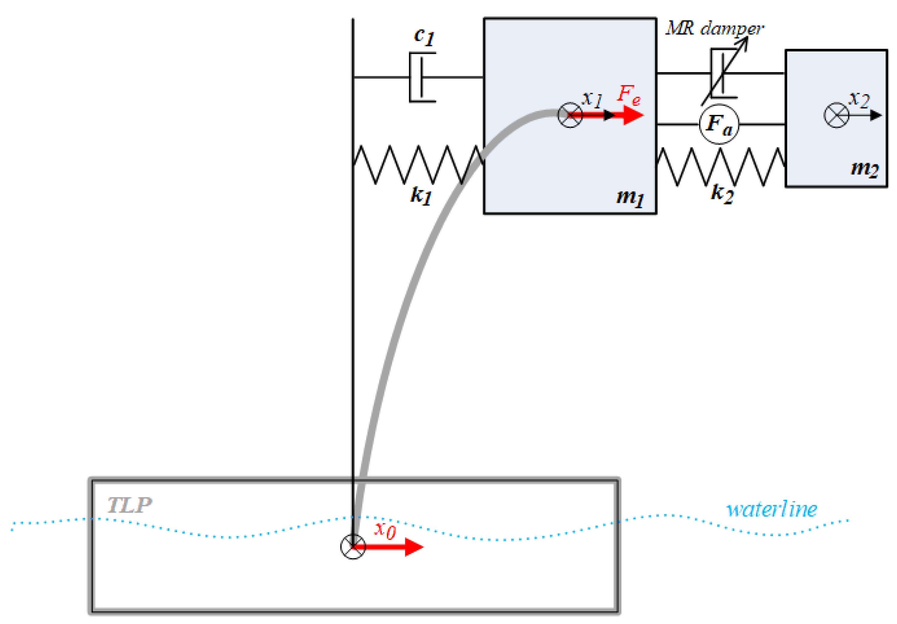
Section 2, let us assume:
,
,
,
, thus:
where:
is the MR damper force as described in [
25,
42] with parameters tuned to the present application as given in
Table 4;
is the MR damper control current,
is the actuator force [
30],
is the nacelle horizontal excitation force, and
is the TLP surge that is assumed to be independent of the wind turbine tower-nacelle system bending in this research, as the NREL 5.0MW 1st tower bending modal mass is small in relation to the TLP structural mass plus an added mass due to the outgoing waves created by the floater motion [
41]. The force produced by the MR damper includes electric current
dependent friction force and viscous damping as well as stiffness components with a scaling parameter
.
The MR damper current limitation to
range (
) and the actuator output nominal force limitation to
range were assumed as in [
30]:
The regarded quality function (8) is:
to account for the protected structure relative displacement (i.e., tower deflection)
and relative velocity (tower deflection rate)
minimisation, the protected structure (nacelle) acceleration
minimisation, the TVA stroke
and relative velocity
minimisation, the MR damper coil current
and force
minimisation, and the actuator force
and power
minimisation, where:
The newly introduced term
implementation, being the original contribution of current research, is intended to minimise the protected structure (i.e., nacelle/rotor with its sensitive instrumentation) acceleration. As the structure acceleration increases with the square of the frequency (for the constant oscillation displacement amplitude), this term is aimed to minimise predominantly higher frequency content of the displacement
(thus minimising the acceleration
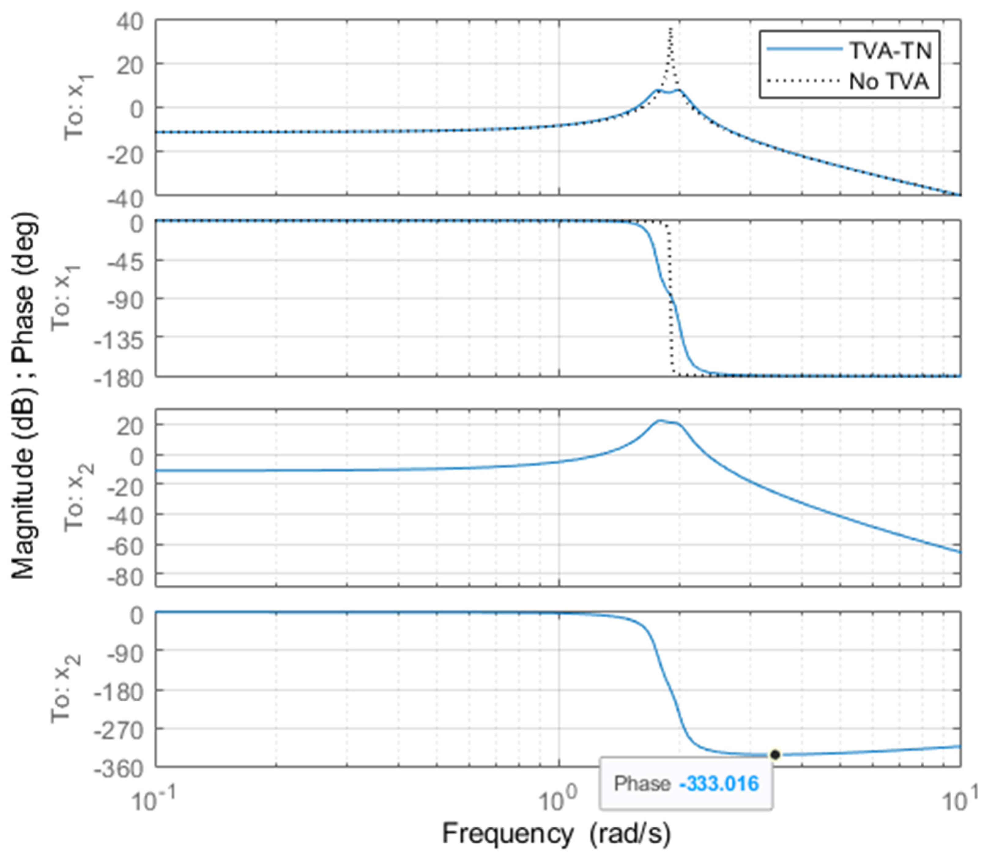
). At these, higher frequencies, TVA mass vibrates at a close antiphase to the protected structure’s mass – see
x1 vs
x2 phase diagrams (
Figure 2). Thus, the minimisation of the high frequency content of
with the use of appropriate
weight consequently reduces moving away the protected structure and the TVA (due to the close antiphase). This in turn reduces the TVA stroke amplitude and MR damper force amplitude, which will be proven in the
Control results section.
Let us consider he Hamiltonian in a form (10):
If
pair is an optimal control process, there exists an adjoint vector function
satisfying:
with a transversality condition:
so that
maximises the Hamiltonian over the set
for almost all
(see details in [
52]). For the regarded system, the adjoint (co-state) vector is:
whereas:
and:
with:
The Hamiltonian therefore takes the form (16):
The Hamiltonian maximisation conditions [
52] are:
with the appropriate sign change conditions, where:
Fixing an attention on
range of
, equation (17) results in (
):
or:
Analogically to [
26]:
where
is the right-hand side of equation (20).
From condition (18) we obtain (
):
Fixing an attention on
range of
, equation (22) results in proposition (23abc), analogically to [
30]:
- 1)
- 2)
(22) is fulfilled and
exhibits
sign change (Hamiltonian maximisation) for:
- 3)
- 4)
(22) is fulfilled and
exhibits
sign change for:
only; thus:
- 5)
- 6)
(2) is fulfilled and exhibits sign change for:
- 7)
only; thus:
4. Test Conditions
The TLP surge
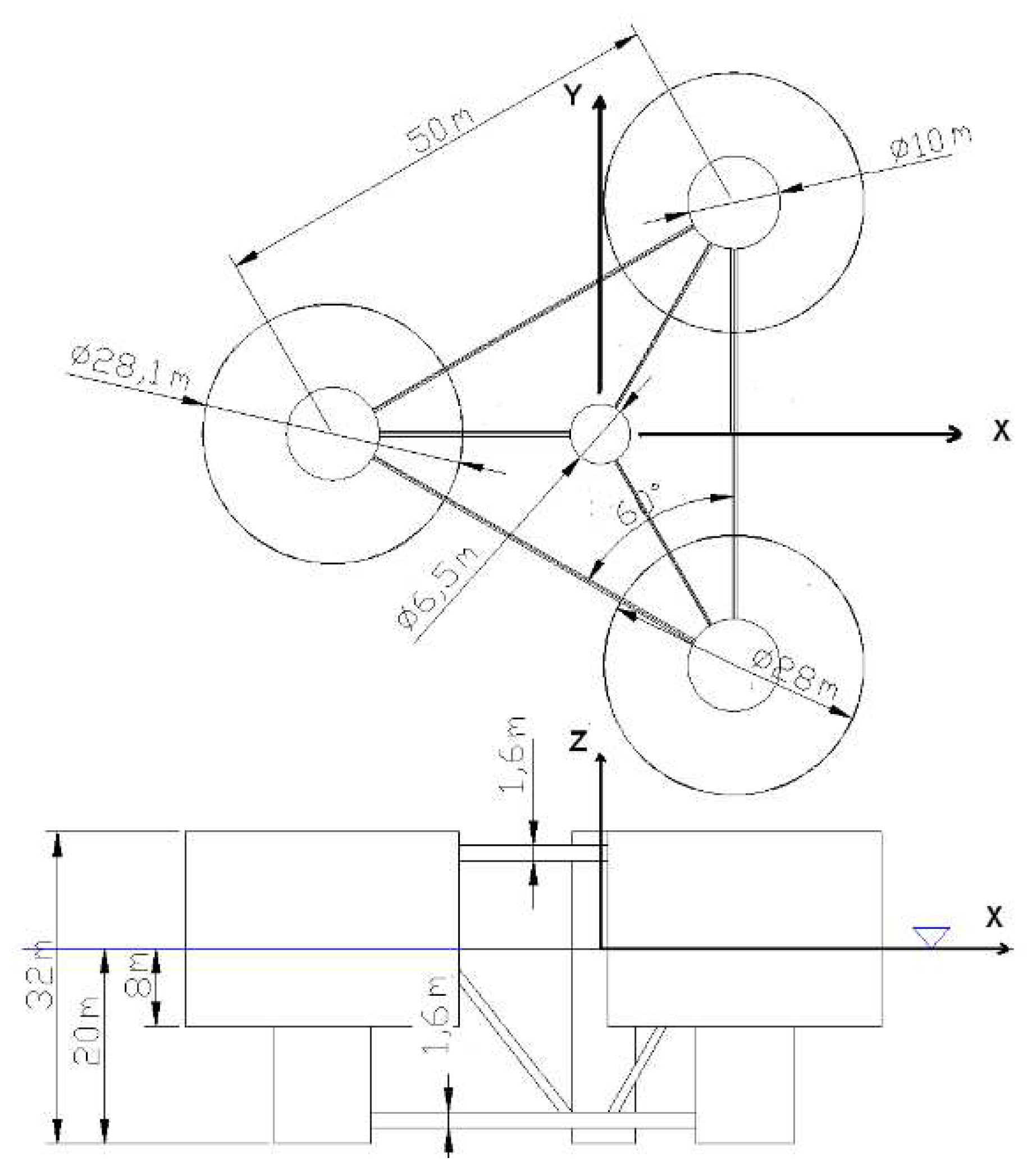
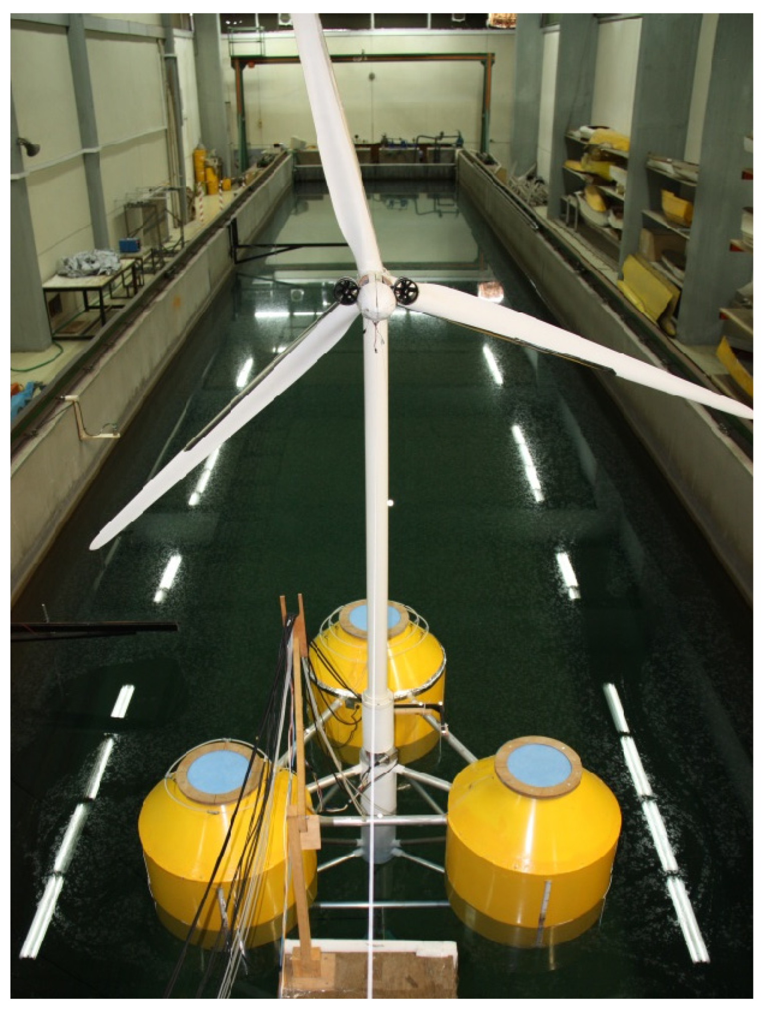
realisations used in this research correspond to the response of the platform under the action of an ocean wave spectrum of Bretschneider type. The examined TLP platform is shown in
Figure 3 and
Figure 4. It forms a floating basis for the installation of a 5MW NREL offshore wind turbine and combines also three wave energy devices, i.e., three vertical cylinders at the vertices of the triangle, which provide the required buoyancy. Each of them is surrounded by a thin skirt, open at its lower end, forming the oscillating water column (OWC) chamber. A central vertical cylinder is also included in the arrangement, for the installation of the wind turbine. All the cylinders of the hull of the platform are structurally connected and supported by cylindrical bracing.
The mooring system of the platform follows the tension leg concept. Three tendons connect the bottom of the corner cylinders to the sea bed foundation, providing also the required pretension for the stabilization of the platform and for station keeping.
The weight groups of the platform and the tendon characteristics are summarised in
Table 2. In order to examine the hydrodynamic behaviour of such a system, an extensive set of experiments were conducted on a scaled down model of the platform (scale 1:40), in the wave tank of the Laboratory for Ship and Marine Hydrodynamics of the National Technical University of Athens (NTUA).
The Froude scaling law for dynamic similarity was followed, for the modelling of the wave environment and the seakeeping behaviour of the platform. Experiments were conducted for a wide range of incident waves’ periods and amplitudes, both harmonic and irregular, corresponding to the sea-states the TLP is expected to encounter in the Aegean Sea.
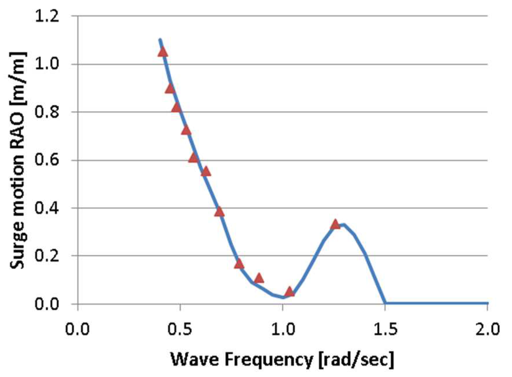
Figure 5 depicts the measured surge response amplitude operators, RAOs (i.e., surge motion amplitude due to a harmonic wave of unit amplitude).
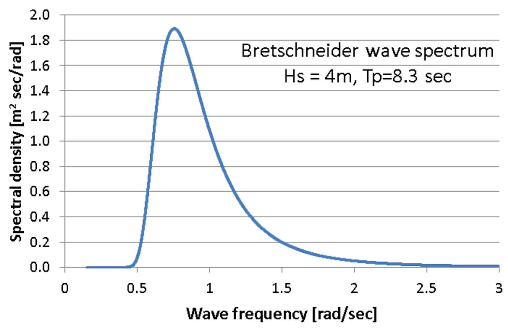
For the installation location considered in the Aegean Sea, the most probable severe wave state can be described by a Bretschneider wave spectrum
S(
ω) (
Figure 6) having a significant wave height
Hs = 4 m and a peak period
Tp = 8.3 s. The corresponding spectrum of the surge response (24) can be found through the combination of the sea wave spectrum and the surge motion
RAOs:
On the basis of the surge spectrum, ten random realizations (numbered 0 through 9) of surge motion were produced by combining the spectral density and random phases for individual motion components.
The external excitation applied on the tower-nacelle structure through the rotor is mainly due to changeable aerodynamic loads. The wind realisations at the height of 90 m above the open sea were generated using the Weibull distribution with a scale parameter of 10 and shape parameter of 2.0, resulting in 8.86 m/s mean wind speed and 4.63 m/s standard deviation. The horizontal nacelle excitation force
was then calculated using the rotor thrust data from ‘Steady-state responses as a function of wind speed’ characteristics [
35], which is generally consistent with [
53].
The most severe vibration response case of uniaxial excitations was assumed. Ten Bredsneider spectrum ocean wave realisations 0÷9 were paired with ten Weibull distribution wind patterns 0÷9, 2500 seconds in length each, 1 ms of time resolution, as described above. Due to a continual thrust asymmetry during all the 360ᵒ rotor angular positions but six ones (i.e., 0ᵒ, 60ᵒ, 120ᵒ, 180ᵒ, 240ᵒ, 300ᵒ), both tower fore-aft and side-side bending mode is excited, whereas TLP horizontal excitation directions (surge/sway) may vary, too. Current analyses are conducted assuming (H-)MR-TVA direction of operation to be the excitations direction. In a practical implementation, two (H-)MR-TVAs operating along mutually perpendicular directions (side-side / fore-aft) may be installed, or a single (H-)MR-TVA operating along side-side direction (fore-aft vibrations attenuated by the rotor aerodynamic damping and collective pitch control of the blades). The assumed here excitations combinations, including their alignment, are not necessarily in the real world conditions. The analyses of the wave/wind misalignment [
37] suggest side-side TVA installation necessity due to side-side loads being a large contributor to the overall fatigue. The work [
44] indicates that the aerodynamic damping is strongest on the surge motion for unidirectional conditions; thus, a fore-aft TVA may also be essential for wave/wind misalignment.
5. Simulation Setup
The NREL 5MW tower-nacelle 1st bending mode model equipped with passive TVA / MR-TVA / H-MR-TVA located in the nacelle, excited horizontally by the supporting TLP platform surge
and resultant load applied to the nacelle
, was embedded in
MATLAB/Simulink environment, adopting the fixed
ms sampling step. A relatively low TVA mass
m2 of 10 ton (0.35% of the total structure’s mass) was assumed, yielding 2.33%
m2/m1 mass ratio, regarding 1st bending mode mass
m1 of 428.8 ton. As discussed earlier [
30], an increased TVA mass ratio does not yield a proportional efficiency gain, not to mention the spatial and structural support requirements; however, it contributes to lower TVA sensitivity to detuning [
54] and more limited TVA stroke. The selection of 10 ton absorber mass is consistent with [
37]. Therefore, the current study discusses the benefits of implementation of an MR damper (and possibly a small-scale force actuator) to address all the regarded efficiency, stroke / space / structural support limitations and detuning issues, using a smaller absorber mass.
In addition to the MR damper’s and actuator’s static non-linearities discussed above (5)(6)(7), their linear dynamics (25)(26) are also included in the current study:
where
and
are Laplace transforms of actual MR damper and electromagnetic actuator outputs, respectively. However, as the MR damper dynamics (25) may be modelled with a 2nd order inertia, while the electromagnetic actuator time-delayed transfer function (26) [
30] may be modelled with a 2nd order oscillatory dynamics with a 1st order inertia, the corresponding optimal control task would be of the 9th order. This would yield a computational load that was real-time tested to be unrealisable. Thus, the dynamics of the MR damper and the electromagnetic actuator are both embedded in the simulation model of the NREL 5MW tower-nacelle system equipped with a TVA, supported by the TLP, and the actual values of
/
are fed as
/
into equations (4)(8)(11)(21)(23abc) (in this way, the modelled MR damper and force actuator responses inertia and delays influence state and co-state variables’ values as well as
and
control patterns), but they do not augment optimal problem order. This guarantees simplicity of the real-time implementation, while not impairing the overall system performance (partially due to the frequency spectrum of the regarded vibration problem being low in relation to actuators’ dynamics).
All the structural model parameters as in
Table 3 along with the MR damper model parameters (
Table 4) were assumed for the simulations. The value of
A yielding respective
ranges and nominal actuator output force
kN were tuned to the current application. As it was previously proven [
30], the MR damper responds faster than the electromagnetic actuator, while the actuator may cancel the MR damper undesirable (i.e., of improper sign due to its dissipative nature) force. The resultant maximum MR damper force was ca. 50 kN (excluding the more demanding
Mod.GH and
Mod.GH-H solutions), whereas the mean actuator power was up to 6.27 kW for
TVA-TN hybrid solutions; however, less force/power demanding solutions were investigated as well.
7. Control Results
The efficiency of the considered solutions was analysed using the following quality indexes: tower tip relative displacement (i.e., tower deflection) root-mean-square (RMS)
) (
Figure 7 and
Figure 8), tower tip relative displacement (tower deflection) amplitude
) (
Figure 9 and
Figure 10), TVA stroke amplitude
) (
Figure 11 and
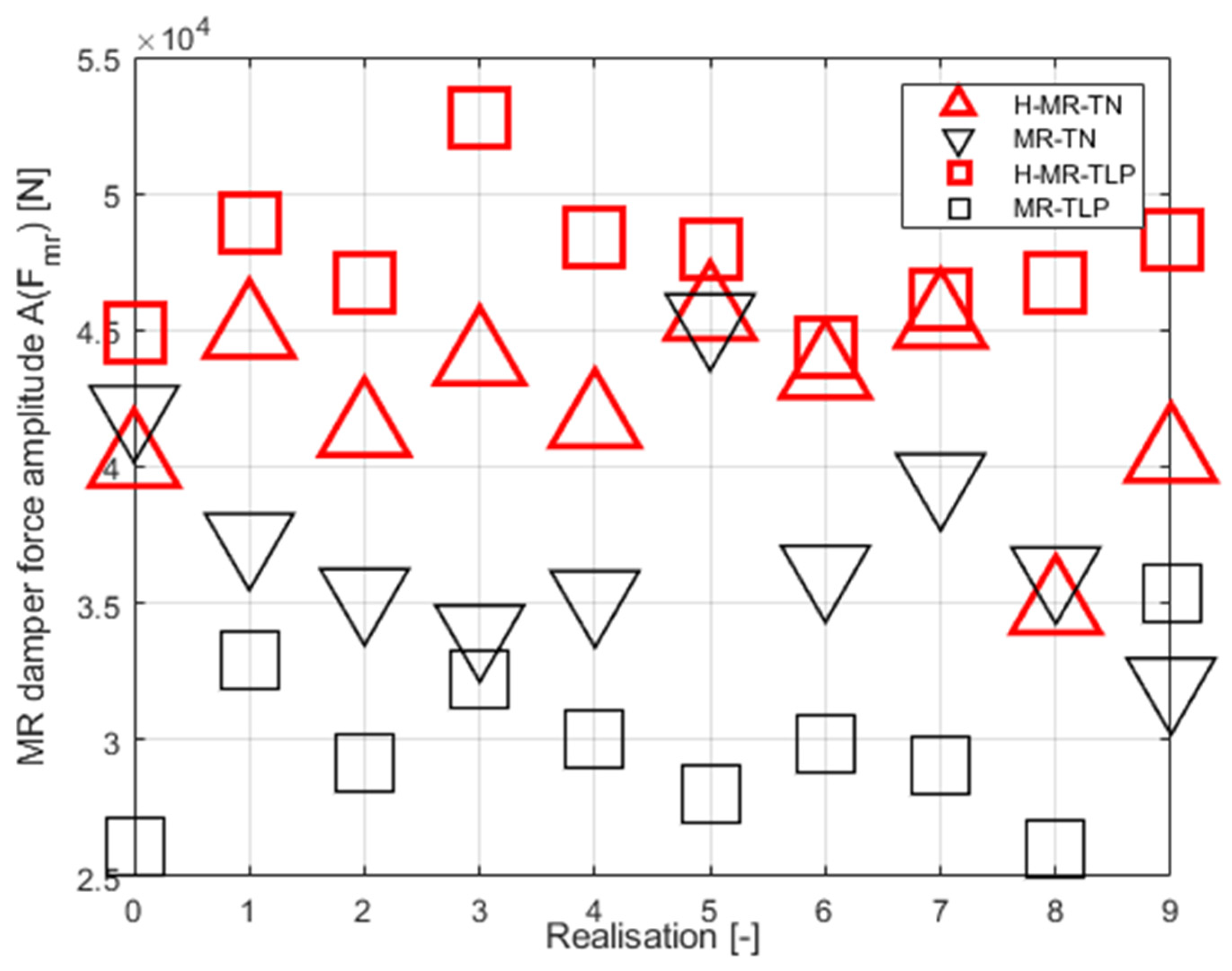
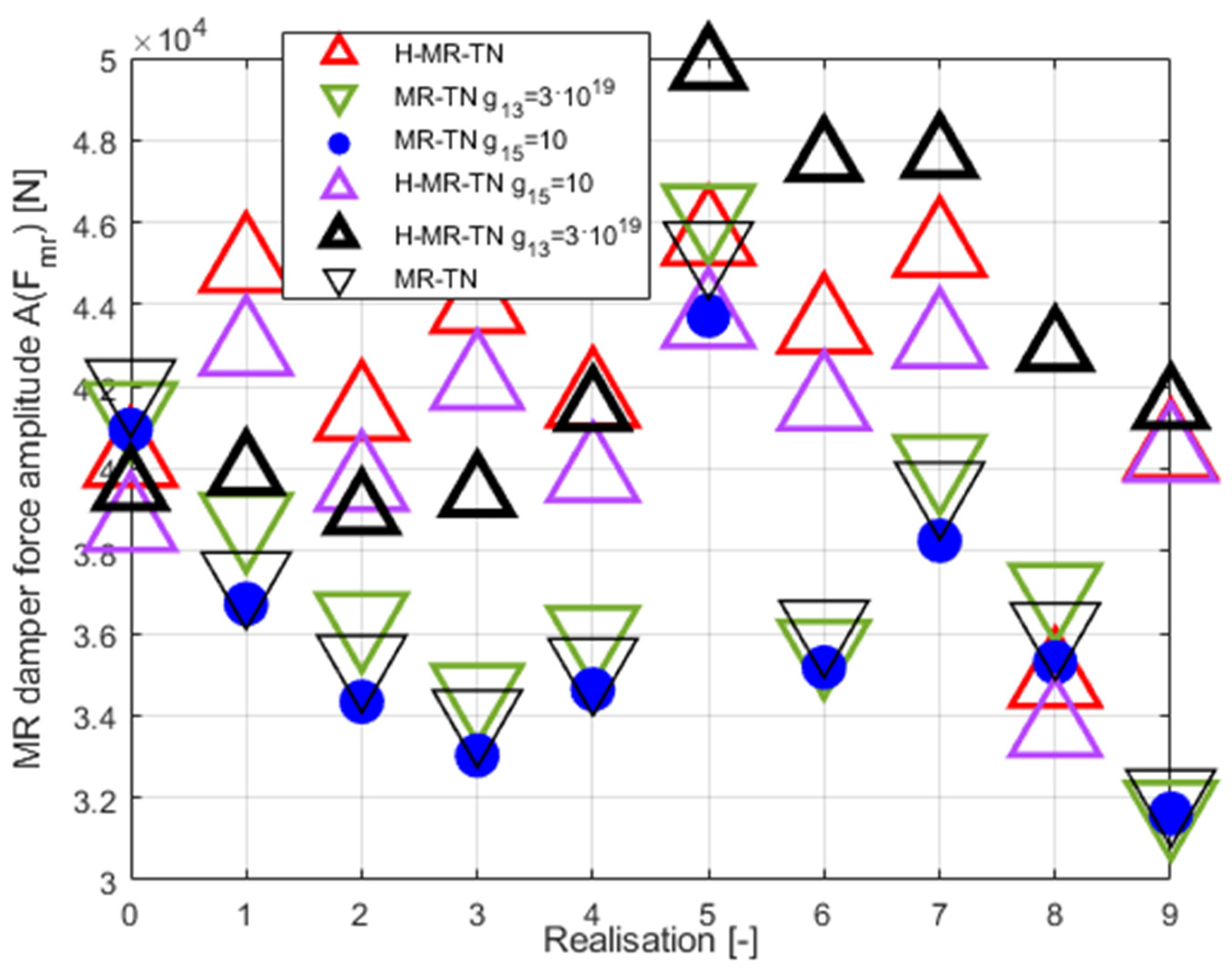
Figure 12), the MR damper force amplitude (
Figure 13 and
Figure 14;
Mod.GH and
Mod.GH-H results excluded due to seriously outlying values – see
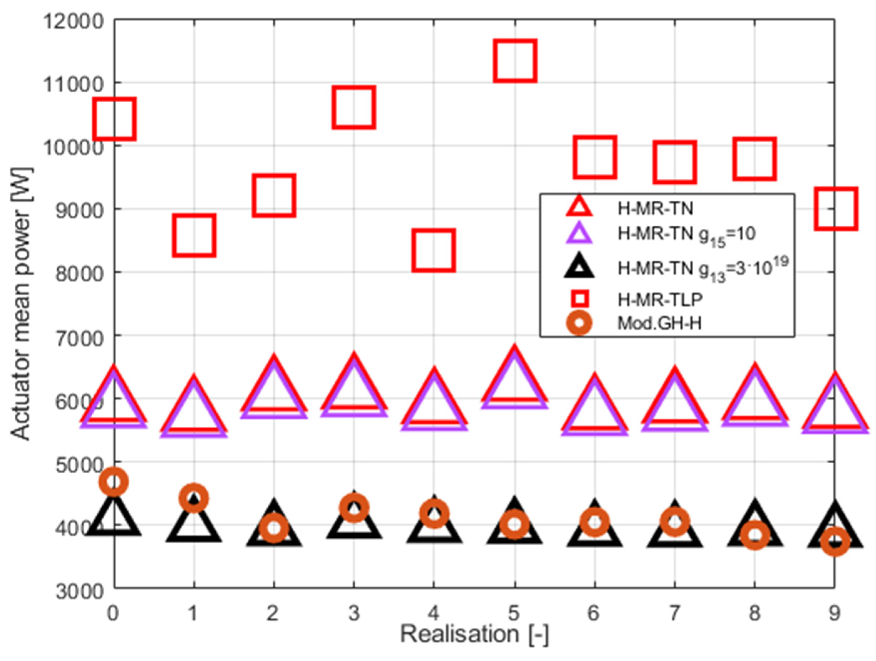
Table 5), and mean actuator power (
Figure 15), along with the time patterns of
,
,
,
, and
(
Figure 16,
Figure 17 and
Figure 18) and
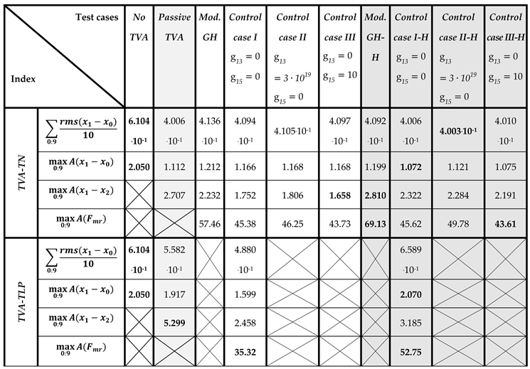
Table 5 (
states for the amplitude i.e., the maximum deviation from the equilibrium state). The
) (equal to standard deviation for zero mean value) value indicates the tower structure operational fatigue, the tower deflection amplitude
indicates the maximum structural stress, whereas the TVA stroke amplitude
determines the spatial and structural applicability of the vibration control solution; the required MR damper force
, associated with the particular solution, conditions its efficiency. In
Table 5, the most favourable results are marked in green bold face, the worst results are marked in red bold face, whereas the runner up solutions are marked in green/red (respectively) regular face.
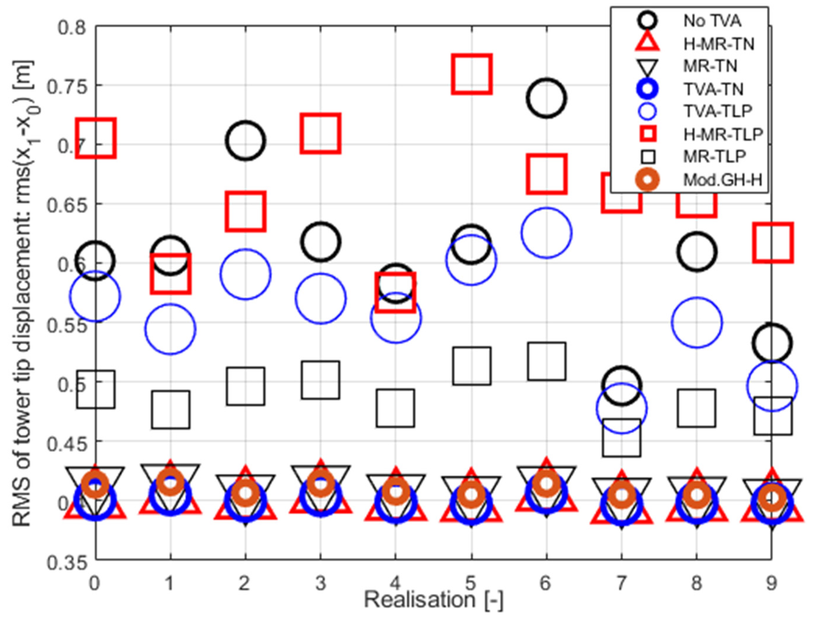
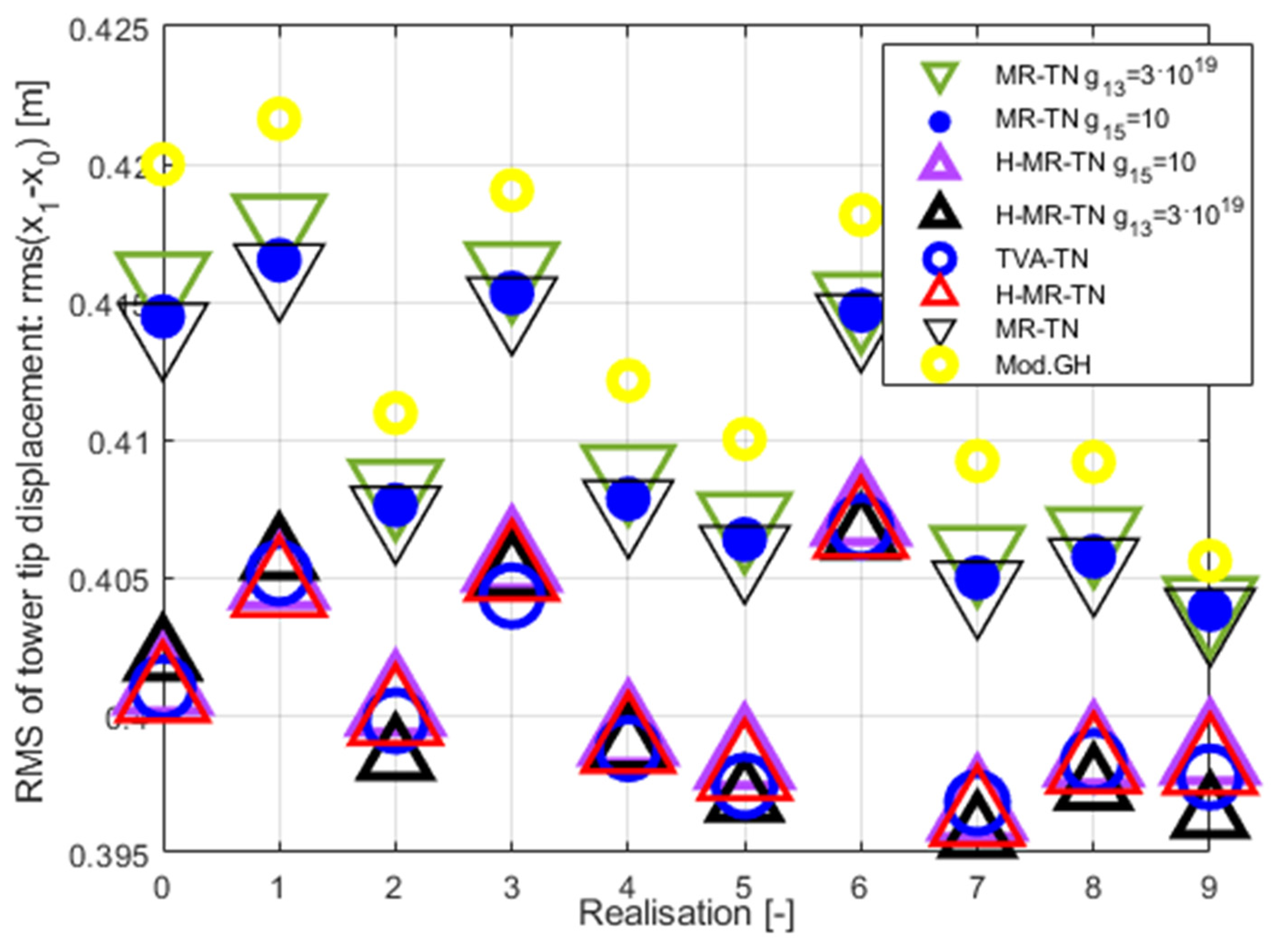
Figure 7 and
Figure 8 present tower tip relative displacement RMSs for a 0÷9 Bredsneider spectrum ocean wave realisations paired with Weibull distribution wind patterns. The TVA was tuned either to the NREL 5MW tower-nacelle first bending mode case (
H-MR-TN legend for H-MR-TVA case;
MR-TN legend for MR-TVA case), or to the TLP surge frequency case (
H-MR-TLP legend for H-MR-TVA case;
MR-TLP legend for MR-TVA case).
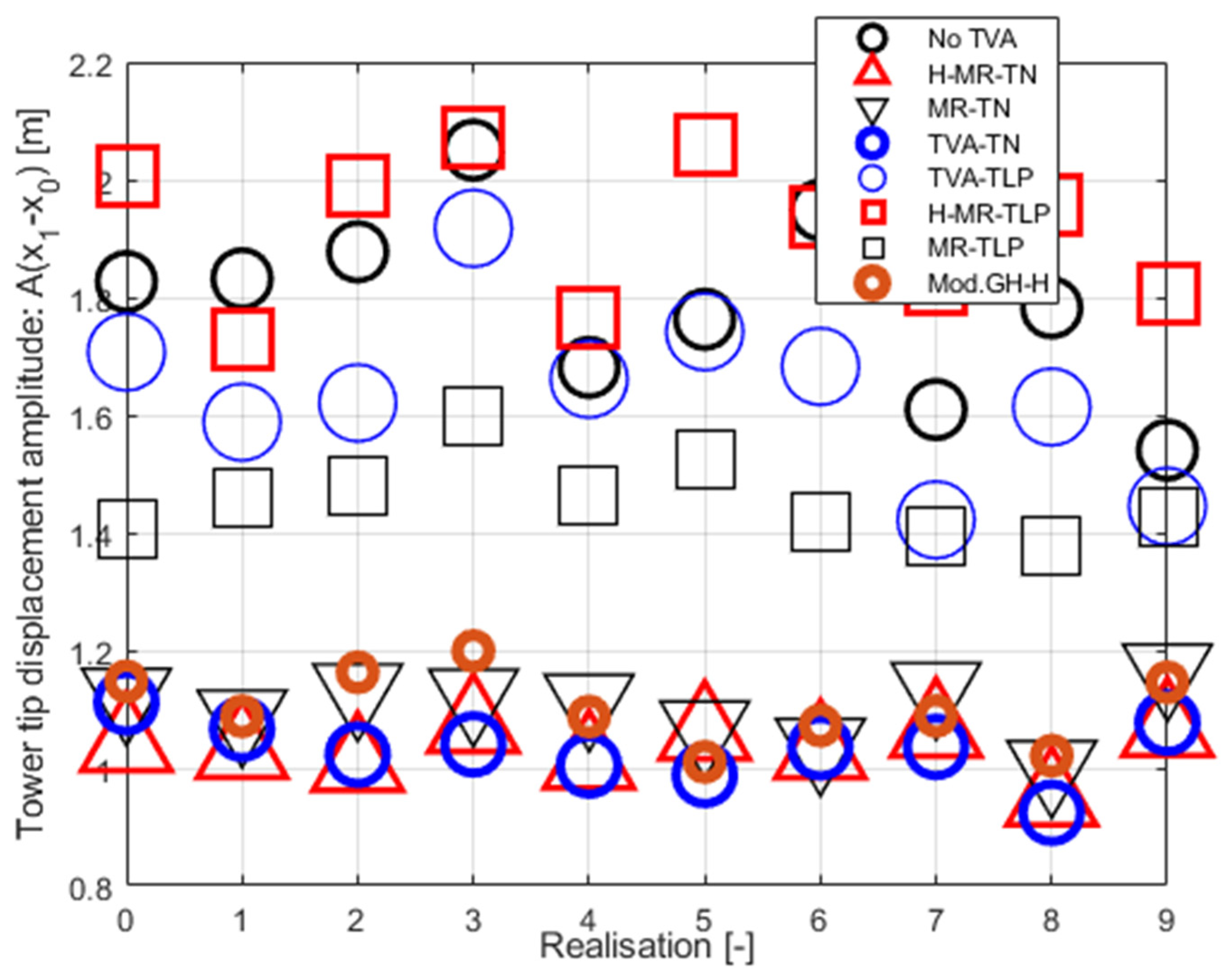
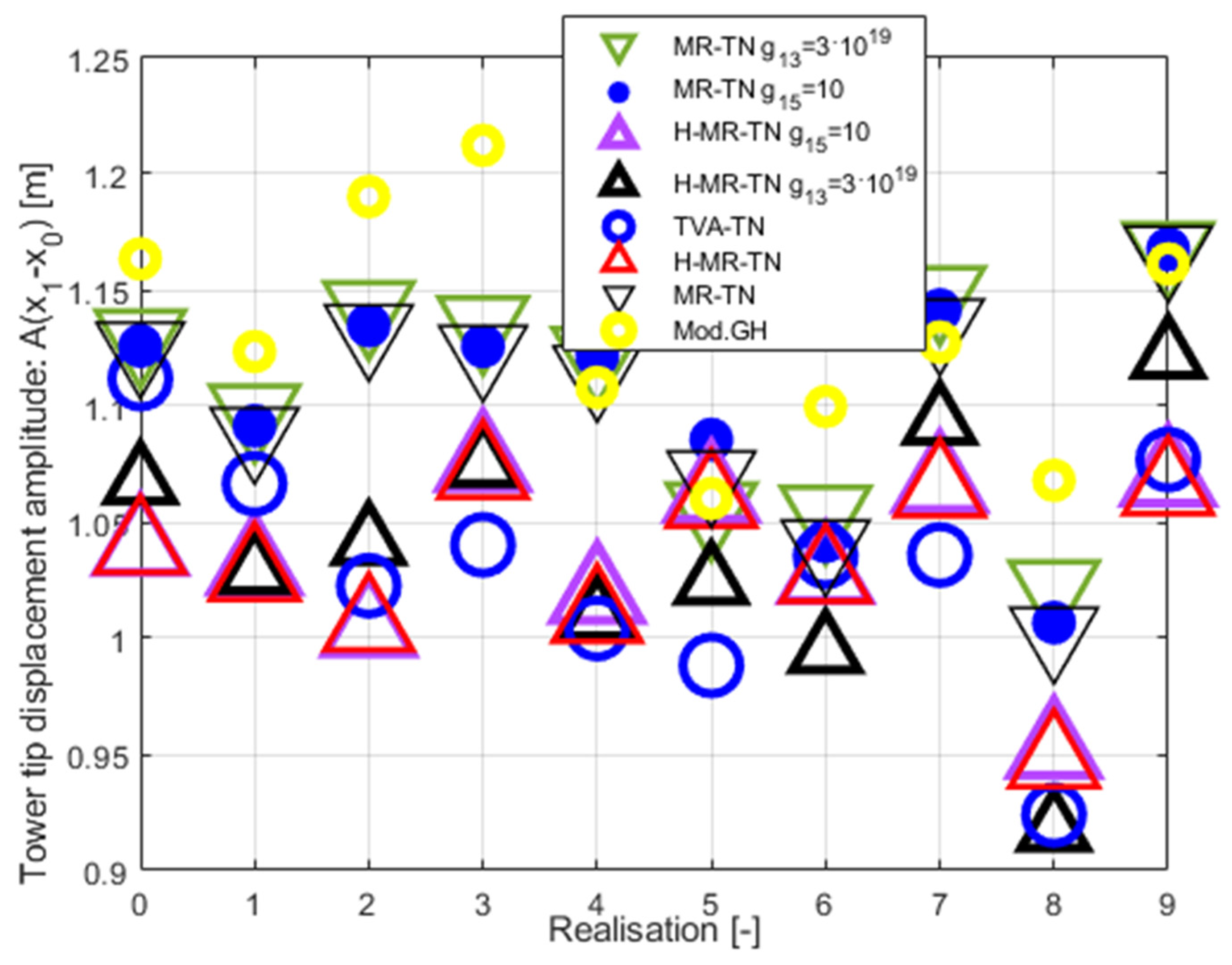
Figure 9 and
Figure 10 present tower tip relative displacement amplitudes for the same set of ten ocean wave / wind realisations, for the TVA tuned to the tower-nacelle first bending mode or the TLP surge frequency. Similarly,
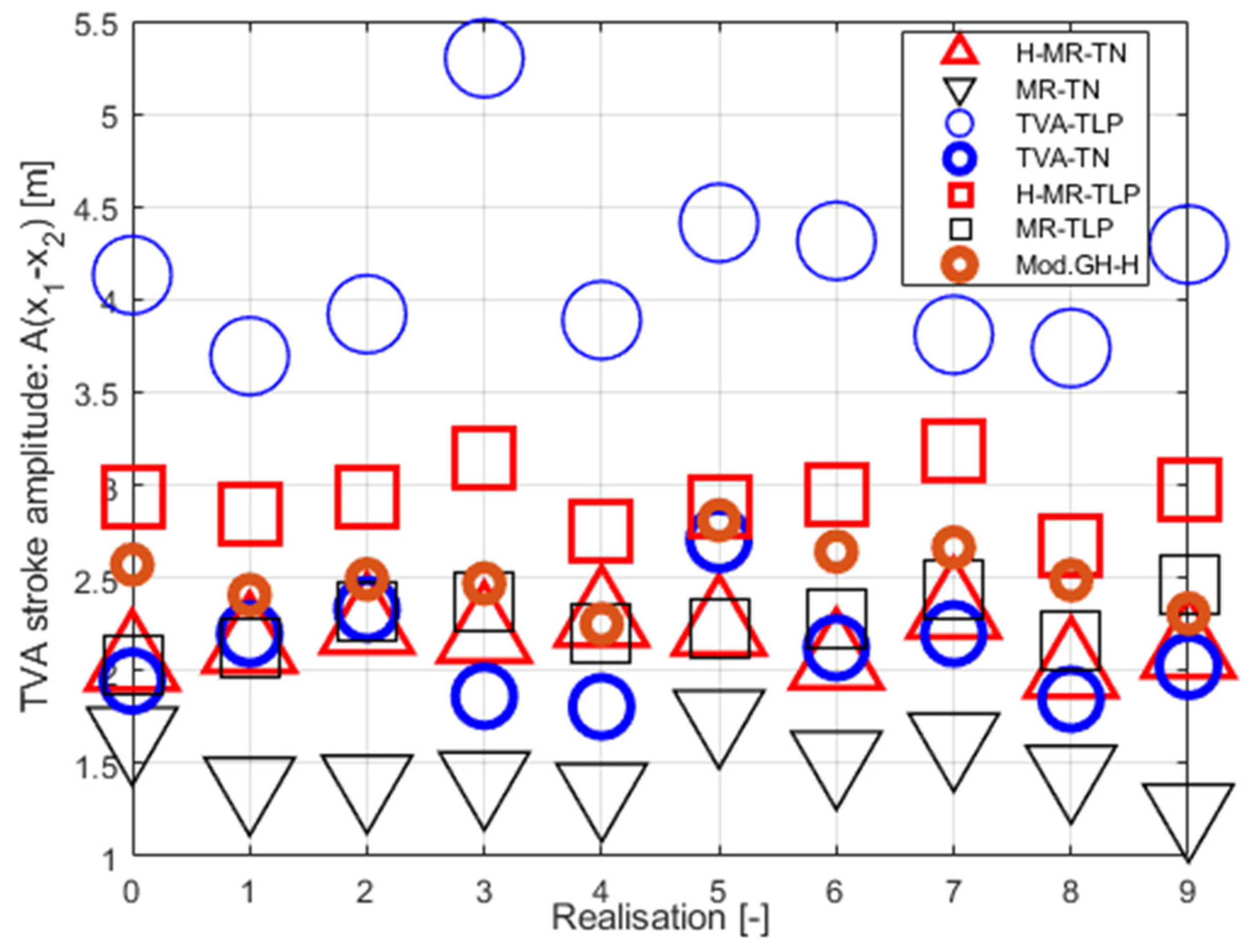
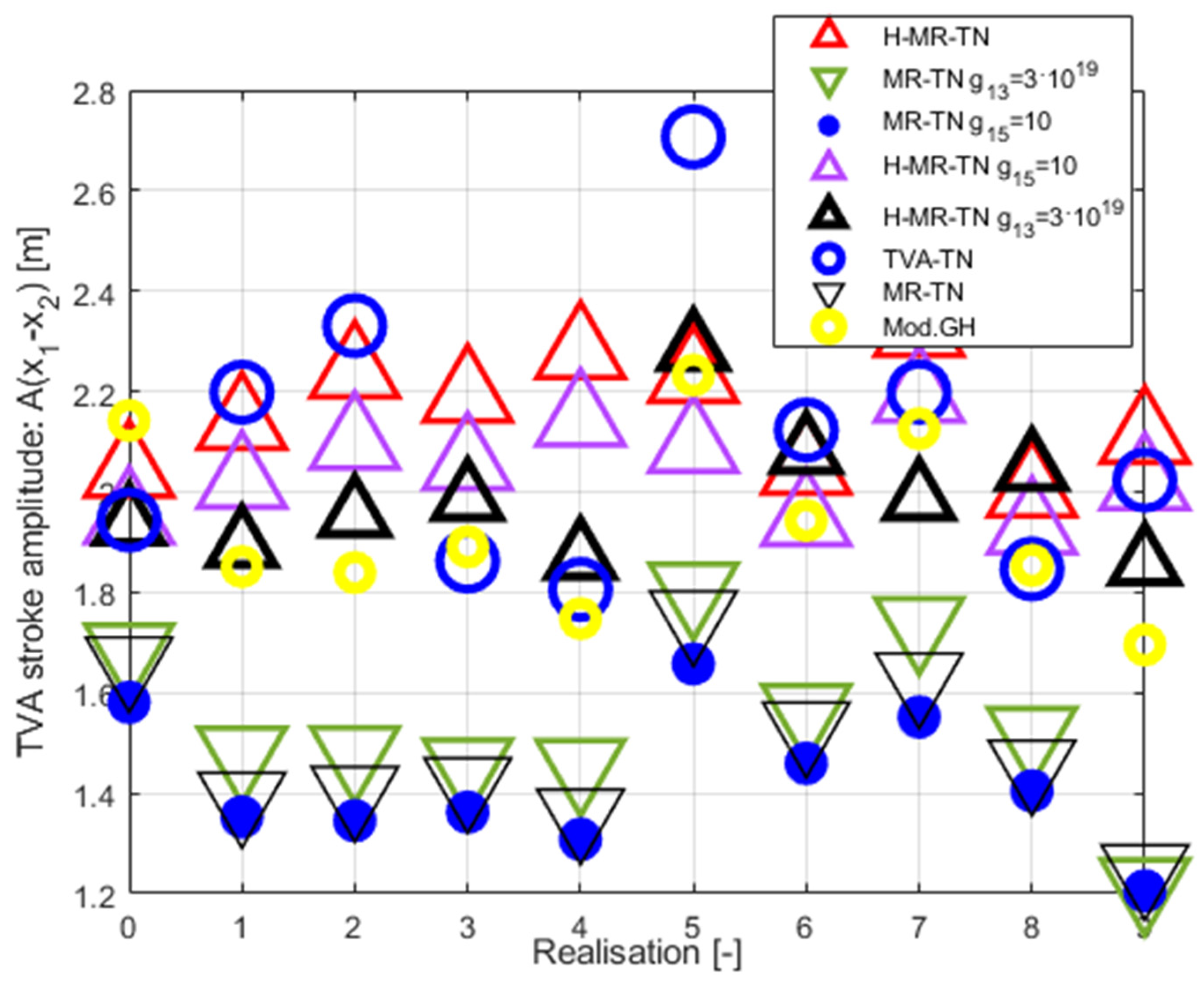
Figure 11 and
Figure 12/
Figure 13 and
Figure 14 present the TVA stroke amplitudes / MR damper force amplitudes (respectively), whereas
Figure 15 presents the mean actuator power values obtained for
TVA-TN cases. The regarded control solutions comparison, covering the vibration attenuation results cumulated over all 0÷9 wave/wind realisations, is presented in
Table 5, including: mean of RMSs of tower tip relative displacements (tower deflections)
, tower tip relative displacements (tower deflections) maximum amplitudes
, TVA stroke maximum amplitudes
, and MR damper force maximum amplitudes
.
On the basis of the obtained results, the general conclusion regarding the TVA tuning frequency is consistent with the previous work [
42], i.e., the
TVA-TN solution is by far superior to the
TVA-TLP one regarding tower deflection RMS / amplitude and TVA stroke values. Thus, the
TVA-TN case only was selected for more thorough analyses described below. The obtained values of the maximum tower tip relative displacement (tower deflection) amplitude
indicate that under the assumed extreme wave/wind conditions the regarded TLP – NREL 5MW structure without a TVA (or any other vibration attenuation solution) or with a TVA tuned to the TLP surge frequency (especially passive and hybrid
TVA-TLPs) are at risk of tower structural failure, which starts to occur when the tower deflection reaches 2.2 m according to [
39] research. All the regarded
TVA-TN solutions provide tower structural deflection safety factor of ca. 2 in accordance with [
39].
The results shown in
Figure 7,
Figure 8,
Figure 9 and
Figure 10 and
Table 5 indicate mixed benefits of the force actuator utilisation in the TVA system. Up to a 2.5 % cumulative (i.e., across all ten ocean wave/wind realisations – see
Table 5) minimisation of the RMS tower deflection, along with up to an 8.8% tower deflection amplitude minimisation in the
TVA-TN case, at the cost of up to 32.5 % increased TVA stroke, is the result of the implementation of this active machinery along with the control circuity and computation resources for the H-MR-TVA system vs the MR-TVA one (BTW, a significant increase in the tower deflection RMSs / amplitudes, TVA strokes, and MR damper force amplitudes may be observed for the active actuator utilisation in the
TVA-TLP case). The MR damper is a semiactive, dissipative device, which force
attenuates the relative travel of the protected structure and the absorber, whereas the active actuator regularly generates the force
of the opposite sign, leading to the primary structure deflection and acceleration minimisation through the TVA stroke extension (see Figs. 18 vs Figs 17), as observed for all the regarded H-MR-TVA systems vs MR-TVA systems (
Table 5).
According to the assumed here amplitude
definition, the TVA effective peak-peak travel distance has to be regarded as
, i.e., twice the value from
Table 5 and Figs. 11–12. Thus, passive TVA solutions with 10 ton absorber mass cannot be implemented along the demanding side-side direction in the nacelle (including the
TVA-TN solution with 5.414 m TVA total travel distance), as well as the
Mod.GH-H solution, without enforcing end-stop collision bumpers, which limit the TVA stroke, but result in efficiency deterioration with regard to the results presented in
Table 5 and Figs. 7–10. Therefore, the promising tower deflection indexes of the passive
TVA-TN system are hardly realisable, considering the NREL 5MW nacelle dimensions (
Table 1) [
37]. The H-MR-TVA travel distance values admissibility must be confirmed prior to implementation, although
control case III-H may be regarded as applicable with proper
weight selection (i.e., a possible increase with regard to
assumed here).
The superiority of the newly developed optimal-based solutions (control case I(-H), II(-H), III(-H)) over the baseline Mod.GH(-H) control law is evident, especially regarding maximum tower deflection amplitude (up to 10.3% reduction) and TVA stroke amplitude (up to 25.7% reduction) values, and the MR damper force amplitudes to even further extend (up to 36.9% reduction). The modified ground-hook approach is devoted to the case when only the protected structure’s relative displacement (tower deflection) has to be minimised. In contrast, the redeveloped control case I(-H), II(-H), and III(-H) use various optimisation fields (i.a., the nacelle relative velocity and acceleration, or the TVA stroke length) embedded in quality function (8), and the MR damper / force actuator constraints embedded in state and co-state equations (4)(11), to produce more favourable results.
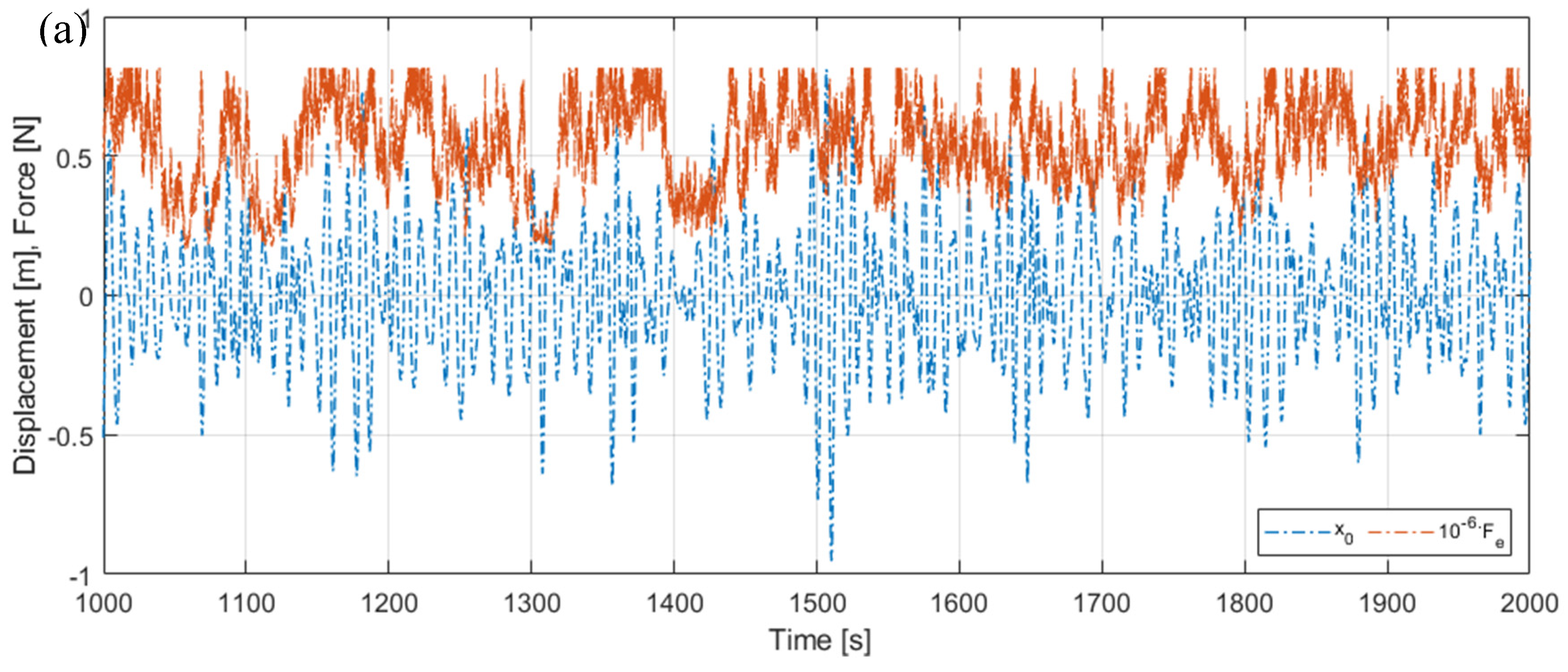
Figure 16,
Figure 17 and
Figure 18 present selected time characteristics obtained for the exemplary wave/wind realisation no. 7: The excitations (TLP surge
combined with the nacelle horizontal load
), the relative displacements of the tower tip (tower deflection
) and the TVA (
), the nacelle acceleration
, the force produced by the MR damper
(and the electromagnetic actuator
for the H-MR-TVA system only), and the MR damper electric current
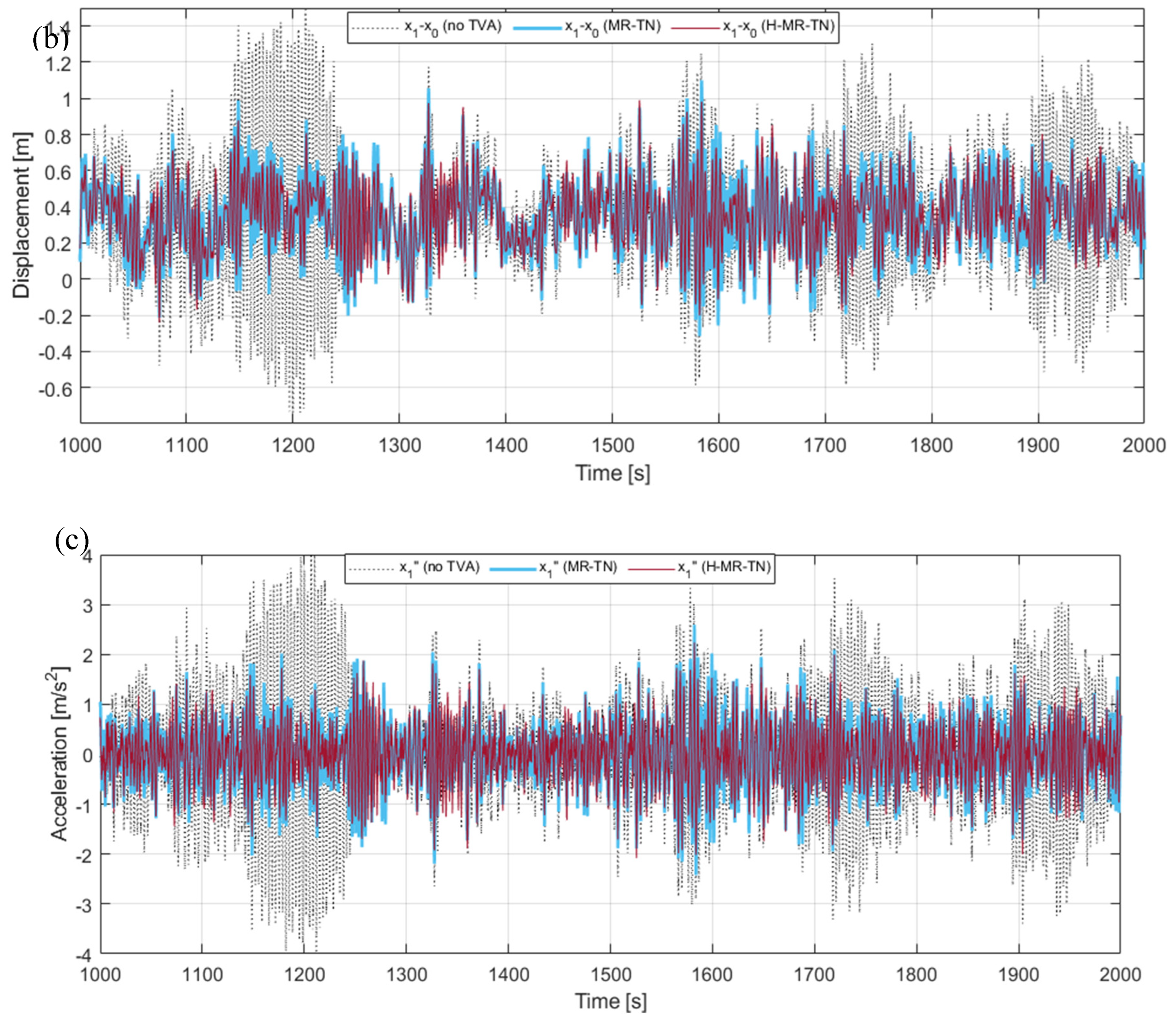
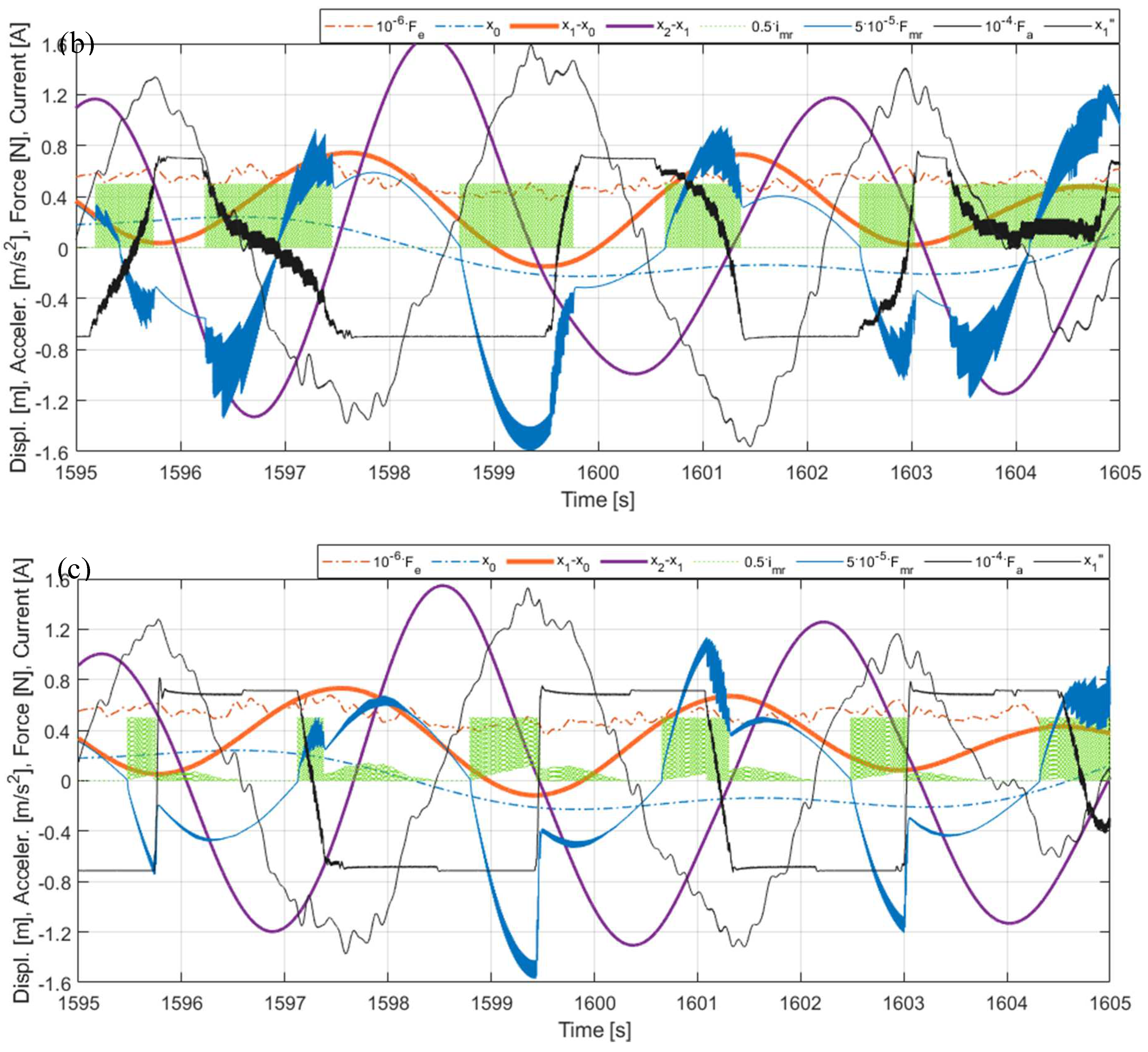
, obtained for the TVA tuned to the NREL 5MW tower-nacelle 1st bending mode vs the structure without the TVA (tower deflection for the latter only; mind the signals multipliers in the legends). Figs. 16 (a)(b)(c) present the excitations time patterns and the corresponding tower tip relative displacement and nacelle acceleration responses obtained for the system without the TVA and two (H-)MR-TVA solutions:
MR-TN (
control case I) and
H-MR-TN (
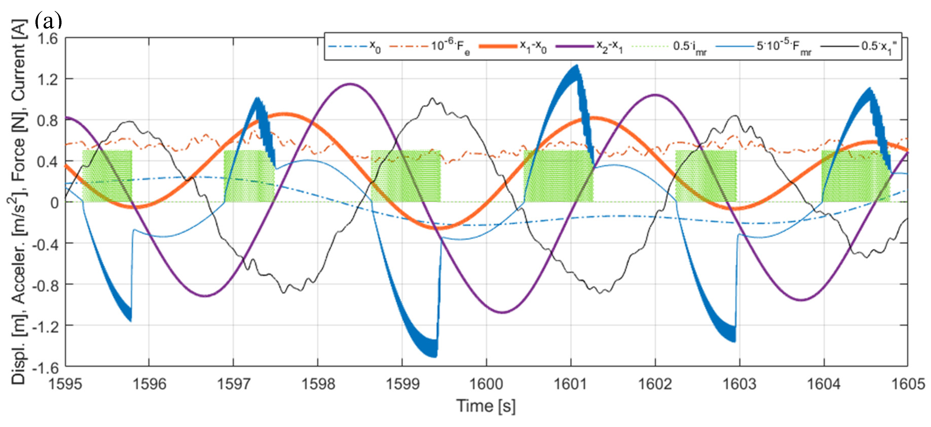
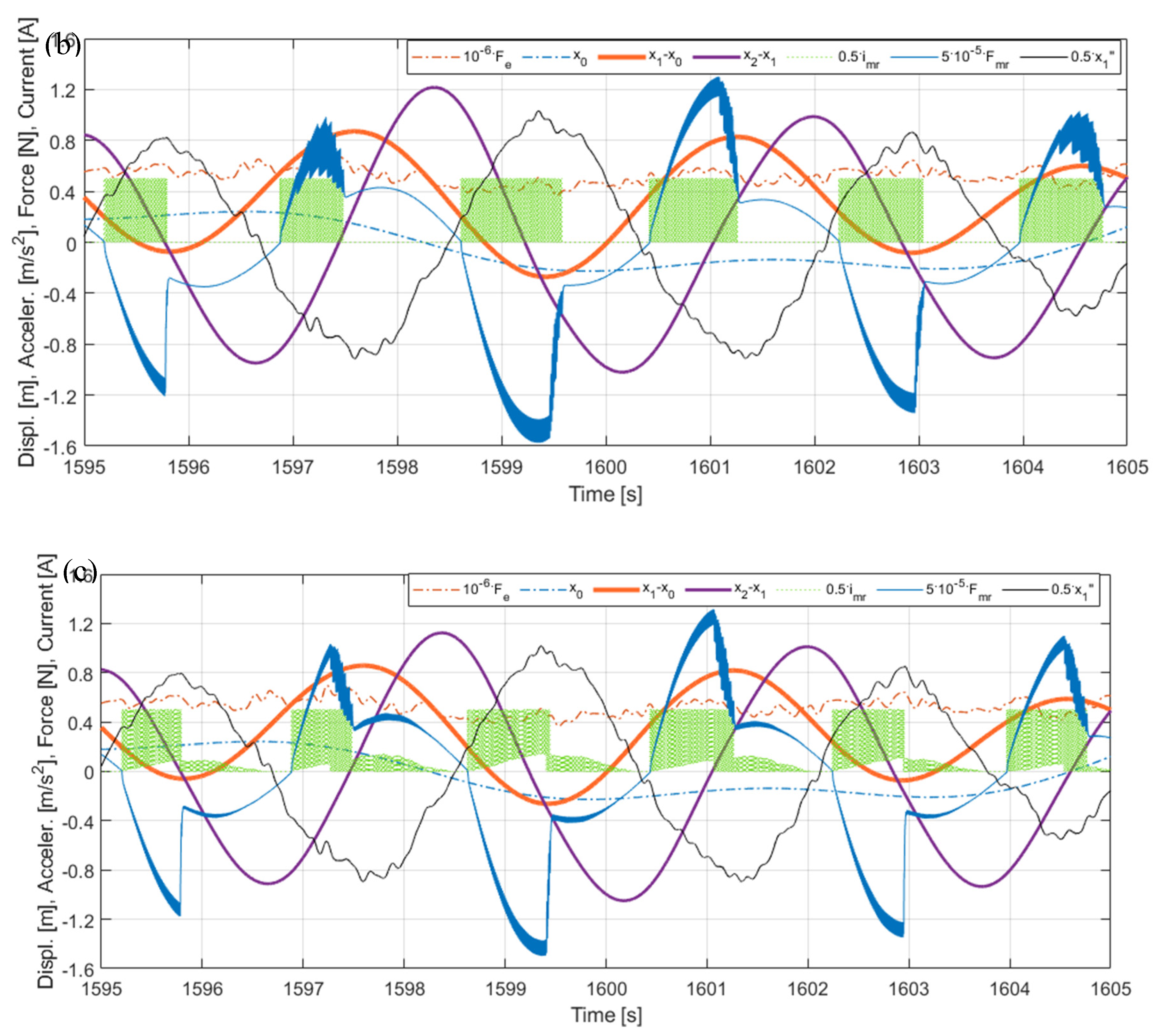
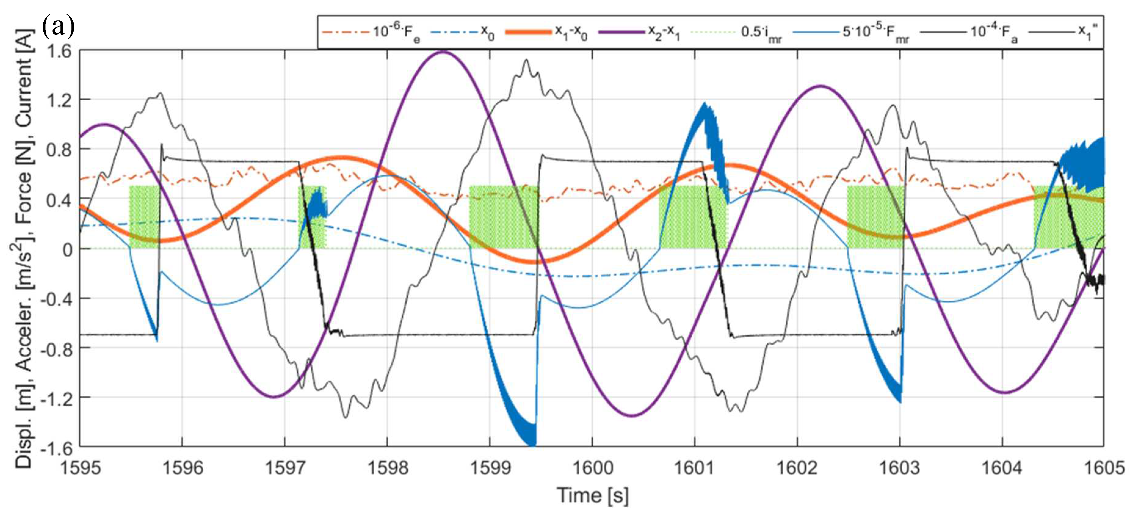
control case I-H). Figs. 17 (a) vs (b) vs (c) show comparable time histories, zoomed in along the time axis to illustrate the control action for the MR-TVA system, while Figs. 18 (a) vs (b) vs (c) – for the H-MR-TVA system. As is evident in Figs. 16, both MR-TVA and H-MR-TVA substantially reduce tower deflection as well as nacelle acceleration amplitudes, although the additional force actuator operation of the latter yields preferable protected structure vibration mitigation results. The operation of the MR-TVA system (Figs. 17),
control case II vs
control case I is characterised by the slightly increased MR damper force modulus mostly during time intervals of high absorber velocity (both
and
) values and the appropriate
sign, opposing absorber’s drawing away form the primary structure. On the other hand, the operation of
control case III solution vs both
control case I and
control case II is indicated with nonzero MR damper current during time intervals when force
opposes the maximum acceleration
values. The optimal control task quality function (8) is aimed to minimise
H2 norm of the included quantities; thus, the maximum amplitude of the TVA stroke is in fact not reduced for
control case II solution vs
control case I (
Figure 12,
Table 5), as for
control case III, but the TVA stroke RMS value is actually slightly lower for
control case II vs
control case I and
control case III (0.346 m vs 0.353 m and 0.348 m, respectively, for the regarded exemplary
Realisation 7 response, see Figs. 17). The operation of the H-MR-TVA system (
Figure 18),
control case II-H and
control case III-H vs
control case I-H, exhibits similar MR damper control
conditions as described for the MR-TVA system, although TVA stroke amplitude and RMS values are both reduced for
control case II-H and
control case III-H with regard to
control case I-H thanks to the force actuator active support. When analysing Figs. 18 (a)(b)(c), it is evident that both actuators’ forces are used in cooperation by the vibration control system, e.g., in
Figure 18 (c) the
modulus increased due to the increased (with regard to Figs. 18 (a)(b)) MR damper current
is reflected by decreased
modulus. Moreover, most
transients are accompanied by the
support, as the MR damper response (25) is faster than the assumed electromagnetic force actuator’s (26). The MR damper force
support for the
control case II-H solution, as visible in
Figure 18 (b), also leads to the mean actuator power reduction (see
Figure 15,
H-MR-TN g13=3.1019 legend).
The implementation of the protected structure’s acceleration term
in the quality index (8) reduces the TVA stroke amplitude
more effectively than using
term and, apart from that, the required MR damper force amplitude is also reduced, as reflected in
Figures 12, 14, 17 and 18 and
Table 5. It also is worth to mention that
term used here for the MR-TVA system (
control case II) is ineffective in
minimisation (see
Figure 12 and
Figure 17 (b), and
Table 5); at the same time, it marginally deteriorates the primary structure response (
Figure 8,
Figure 10 and
Figure 17 (a)(b),
Table 5). For the H-MR-TVA,
control case II-H yields both less favourable primary structure deflection and less favourable TVA stroke length than
control case III-H, i.e., similar mean tower deflection RMS values, but 4.3% higher maximum tower deflection amplitude, and 4.3% higher maximum TVA stroke amplitude over all wave/wind realisations, see
Table 5. On the contrary, the
term implementation for the MR-TVA (
control case III) results in 9.0% and 5.7% maximum TVA stroke amplitude reduction over all wave/wind realisations with regard to
control case II and
control case I, respectively, while its primary structure response differences with regard to the preferable
control case I (
Figure 8,
Figure 10 and
Figure 17,
Table 5) are negligible (within 0.2%). The implementation of the
term for the H-MR-TVA system (
control case III-H) results in 6.0 % maximum TVA stroke amplitude reduction with regard to the baseline
control case I-H, while the primary structure response differences are negligible (within 0.3%), as for the MR-TVA system. The TVA travel distance reductions are obtained thanks to the sole control algorithm alteration. Thus, no additional hardware/software resources are necessary, while this pure advantage is accompanied with up to 4.4% reduction in the MR damper force amplitude vs the
control case I(
-H) solutions.
With regard to the limited TVA stroke, the most favourable vibration control solution is the semiactive MR-TVA control case III implementation, providing favourable cumulative primary structure deflection indexes (over all wave/wind realisations) at the lowest obtained TVA travel distance. A possible alternative is the hybrid H-MR-TVA control case III-H implementation, providing even more favourable cumulative primary structure deflection indexes and reduced nacelle acceleration levels thanks to the utilisation of the force actuator of relatively low mean power (up to 6.15 kW), which side effect is, however, the increased TVA travel distance.
8. Conclusions
The purpose of this research was the implementation and numerical study of the nonlinear optimal-based vibration control solutions for the full-scale TLP – NREL 5MW wind turbine tower-nacelle model with the (H-)MR-TVA vibration reduction system, using the MR damper control, combined with the force actuator operation or independent, under the excessive wave/wind polyperiodic excitations yielding continual transient vibration states.
On the basis of the obtained results, the TVA-TN approach (tuned to the tower-nacelle 1st bending mode) is by far superior to the TVA-TLP one regarding the tower deflection amplitude/RMS and TVA stroke amplitude values. All the regarded TVA-TN solutions provide tower deflection safety factor of ca. 2, while a structure without any vibration reduction solutions or with a TVA tuned to the TLP surge frequency (especially passive and hybrid TVA-TLPs) are at risk of tower structural failure. Thus, TVA-TN solutions are the core of the current research.
The implementation of the protected structure’s acceleration and nonzero relative velocity terms in the quality function (8) results in 23.2% / 21.5% maximum TVA stroke amplitude reduction along with 3.3% / 9.7% maximum tower deflection amplitude reduction for the MR-TVA / H-MR-TVA case vs the baseline, previously developed, modified ground-hook law Mod.GH / Mod.GH-H (respectively) devoted to the single objective of the protected structure deflection minimisation. The sole usage of protected structure’s acceleration term yields ca. 6 % maximum TVA stroke amplitude reduction with regard to the control case I and I-H approaches, while the tower deflection response differences are negligible. The TVA travel distance reductions are obtained thanks to the sole control algorithm enhancement. Thus, no additional resources are necessary, while this pure advantage is accompanied with a reduction in the MR damper force that is necessary for the TVA operation. The protected structure’s acceleration term utilisation produces the TVA stroke amplitude reduction more efficiently than standard TVA relative displacement term usage as in the previously developed approach (the latter being ineffective for the MR-TVA system implementation) which, in turn, efficiently reduces the TVA stroke RMS (H2 norm) values and, apart from that, the required mean actuator power for the H-MR-TVA system implementation.
With regard to the limited TVA stroke, the most favourable vibration control solution is the semiactive MR-TVA control case III implementation, providing favourable cumulative primary structure deflection indexes at the lowest obtained TVA travel distance. A possible alternative may be the hybrid H-MR-TVA control case III-H, providing even more favourable primary structure deflection qualities and reduced nacelle acceleration levels thanks to the utilisation of the force actuator of the relatively low power (ca. 6 kW), which side effect is, however, the increased TVA stroke amplitude. The analysed passive TVA systems (both TVA-TN and TVA-TLP) with relatively small 10 ton absorber mass can hardly be implemented in the nacelle, especially along the demanding side-side direction, without enforcing end-stop collision bumpers, which result in the efficiency deterioration.
The results of the current study may be used in the design process of the full-scale vibration reduction system attached to the real-world NREL 5MW-class floating, TLP-based, wind turbine structure. No offline calculations, MR damper or force actuator force tracking, disturbances or dominant frequency assumption is necessary for proper real-time implementation.
Figure 1.
Diagram of a regarded system with an H-MR-TVA.
Figure 1.
Diagram of a regarded system with an H-MR-TVA.
Figure 2.
Bode diagram of a regarded simulation model with and without TVA.
Figure 2.
Bode diagram of a regarded simulation model with and without TVA.
Figure 3.
TLP platform dimensions.
Figure 3.
TLP platform dimensions.
Figure 4.
TLP with NREL 5MW model in the experimental facilities.
Figure 4.
TLP with NREL 5MW model in the experimental facilities.
Figure 5.
Surge motion RAOs for the TLP FOWT.
Figure 5.
Surge motion RAOs for the TLP FOWT.
Figure 6.
Wave spectrum considered.
Figure 6.
Wave spectrum considered.
Figure 7.
RMS of tower tip relative displacement ) for and Results summary.
Figure 7.
RMS of tower tip relative displacement ) for and Results summary.
Figure 8.
RMS of tower tip relative displacement ) for and . TVA tuned to the NREL 5MW tower-nacelle 1st bending mode.
Figure 8.
RMS of tower tip relative displacement ) for and . TVA tuned to the NREL 5MW tower-nacelle 1st bending mode.
Figure 9.
Tower tip relative displacement amplitude ) for and . Results summary.
Figure 9.
Tower tip relative displacement amplitude ) for and . Results summary.
Figure 10.
Tower tip relative displacement amplitude ) for and . TVA tuned to the NREL 5MW tower-nacelle 1st bending mode.
Figure 10.
Tower tip relative displacement amplitude ) for and . TVA tuned to the NREL 5MW tower-nacelle 1st bending mode.
Figure 11.
TVA stroke amplitude ) for and . Results summary.
Figure 11.
TVA stroke amplitude ) for and . Results summary.
Figure 12.
TVA stroke amplitude ) for and TVA tuned to the NREL 5MW tower-nacelle 1st bending mode.
Figure 12.
TVA stroke amplitude ) for and TVA tuned to the NREL 5MW tower-nacelle 1st bending mode.
Figure 13.
MR damper force amplitude ) for and . Results summary.
Figure 13.
MR damper force amplitude ) for and . Results summary.
Figure 14.
MR damper force amplitude ) for and . TVA tuned to the NREL 5MW tower-nacelle 1st bending mode.
Figure 14.
MR damper force amplitude ) for and . TVA tuned to the NREL 5MW tower-nacelle 1st bending mode.
Figure 15.
Mean actuator power .
Figure 15.
Mean actuator power .
Figure 16.
Time patterns for exemplary Realisation 7: (a) TLP surge combined with the nacelle horizontal load , (b) tower tip relative displacement (tower deflection), (c) nacelle acceleration.
Figure 16.
Time patterns for exemplary Realisation 7: (a) TLP surge combined with the nacelle horizontal load , (b) tower tip relative displacement (tower deflection), (c) nacelle acceleration.
Figure 17.
Time responses for MR-TVA tuned to the NREL 5MW tower-nacelle 1st bending mode: (a) Control case I, (b) Control case II, (c) Control case III (Realisation 7).
Figure 17.
Time responses for MR-TVA tuned to the NREL 5MW tower-nacelle 1st bending mode: (a) Control case I, (b) Control case II, (c) Control case III (Realisation 7).
Figure 18.
Time responses for H-MR-TVA tuned to the NREL 5MW tower-nacelle 1st bending mode: (a) Control case I-H, (b) Control case II-H, (c) Control case III-H (Realisation 7).
Figure 18.
Time responses for H-MR-TVA tuned to the NREL 5MW tower-nacelle 1st bending mode: (a) Control case I-H, (b) Control case II-H, (c) Control case III-H (Realisation 7).
Table 1.
NREL 5MW Baseline Wind Turbine parameters [
35,
37]
.
Table 1.
NREL 5MW Baseline Wind Turbine parameters [
35,
37]
.
| Rotor Diameter |
126 m |
| Hub Height |
90 m |
Wind Speed:
Cut-In, Rated, Cut-Out |
3.0, 11.4, 25.0 m/s |
| Rotor Speed: Cut-In, Rated |
6.9, 12.1 rpm |
Rotor Mass
Nacelle Mass
Tower Mass |
110.0 t
240.0 t
347.5 t |
| Nacelle Dimensions |
18 × 6 × 6 m |
Table 2.
TLP platform main particulars [
33]
.
Table 2.
TLP platform main particulars [
33]
.
| Platform mass |
2183 t |
| Displacement |
6086.3 m3
|
| Vertical centre of gravity of the platform (below sea level) |
4.05 m |
| Draft, Freeboard |
20, 12 m |
| Nominal Tendon pretension (each) |
10.8 MN |
| Water depth |
120 m |
Table 3.
TLP – NREL 5MW with TVA-TN/TVA-TLP simulation model parameters.
Table 3.
TLP – NREL 5MW with TVA-TN/TVA-TLP simulation model parameters.
| NREL 5MW tower-nacelle 1st bending mode model |
| m1 |
428.8 t |
| k1 |
1.546 MN/m |
| c1 |
3.542 kNs/m |
| TVA tuned to NREL 5MW tower-nacelle 1st bending mode |
| m2 |
10.0t (2.33% m1) |
| k2 |
34.421 kN/m |
| c2 |
3.352 kNs/m |
| TVA tuned to TLP surge |
| m2 |
10.0t (2.33% m1) |
| k2 |
3.770 kN/m |
| c2 |
1.109 kNs/m |
Table 4.
MR damper simulation model parameters.
Table 4.
MR damper simulation model parameters.
| C1 |
1581 |
| C2 |
38.25 |
| C3 |
12240 |
| C4 |
3570 |
|
1300 |
Table 5.
The test cases – cumulative results over realisations 0÷9 (baseline weights: g11 = 1021, g12 = 1019.
Table 5.
The test cases – cumulative results over realisations 0÷9 (baseline weights: g11 = 1021, g12 = 1019.

