Submitted:
17 January 2024
Posted:
18 January 2024
You are already at the latest version
Abstract
The capability of in-house transient wave-multibody computational tool of ITU-WAVE are extended to predict the wave power absorption with Wave Energy Converters (WECs) arrays placed in front of a vertical breakwater. The analyses of hydrodynamic exciting and radiation forces are approximated solving boundary integral equation at each time interval. The reflection of incoming waves due to a vertical wall is predicted with method of images. The constructive or destructive performance of WECs arrays with different array configurations is measured with mean interaction factor. The behaviour of the exciting and radiation hydrodynamic forces of each WEC due to a vertical wall effect shows considerable differences than those of WECs arrays without a vertical wall influence. When the wave power absorption with WECs arrays with and without a vertical wall effect are compared, it is shown with numerical experiences that WECs placed in front of a vertical wall have much greater effects on wave power absorption. This can be attribute to the hydrodynamic interaction, standing waves, and nearly trapped waves in the gap between a vertical wall and WECs arrays. The analytical and other numerical results are used to for the validation of the numerical results of the present ITU-WAVE computational tool for exciting and radiation forces, and mean interaction factor of WECs arrays which show satisfactory agreements.
Keywords:
mean interaction factor
; absorbed wave power
; multibody interaction
; WECs arrays
; method of images
1. Introduction
The performances of isolated WECs for wave power absorption can be improved using different array configurations of rectangular, square, or linear forms. In addition, single or multimode of motions (e.g., surge, heave, pitch), separation distance between WECs (Kara 2016a), heading angles (e.g., head seas, beam seas), Power-Take-Off systems or control strategies (e.g., discrete, or continuous) (Kara 2010) plays significant role on the performances of WECs arrays. Wave power absorptions could also significantly be improved replacing isolated device with WECs arrays (Kara 2016a). The array configuration results in increasing absorbed wave power due to wave interaction and standing waves between a vertical wall and WECs. Wave power could be exploited either nearshore or offshore environments. The efficiency of WECs arrays and absorbed wave power could be further improved replacing WECs arrays in front of the marine structures (e.g., a vertical wall) (Kara 2022a, 2021, Chatjigeorgiou 2019) or integrating them with breakwaters. The overall cost WECs arrays in the offshore environment increases considerably due to the cost of the maintenance, installations, and operations. However, the overall cost could be decreased significantly by sharing it with existence marine structure and replacing WECs arrays in front of a breakwater or integrating them (Mustapa et.al. 2017) with, such as, a vertical wall.
When wave power absorption of WECs arrays is compared that of isolated WEC, the experimental (Ning et.al. 2016) and numerical (Kara 2016a, Zhao et.al. 2019) analyses show that WECs arrays are superior to isolated WEC. The nearly trapped waves and hydrodynamic interaction in the gap is the reason for the considerably improved wave power absorption with WECs array configurations. The competitiveness of WECs arrays can be further improved and enhanced by exploiting the optimum hydrodynamic interaction in the gap of array system. A vertical wall effect on the efficiency and behavior of WECs arrays due to the wave interaction in the gap between WECs arrays and between a vertical wall and WECs are investigated numerically and experimentally (Kara 2022a,2021, Loukogeorgaki et.al. 2020). The effects of a vertical wall for maximum absorbed wave power are strongly influenced with the separation distance between a vertical wall and WECs arrays as well as between WECs (Schay et.al. 2013). The integration of WECs with breakwater has significant influence in the behavior and performance of WECs arrays with the configurations of floating and stationary systems (e.g., oscillating buoys, overtopping, oscillating water columns) (Ning et.al. 2016).
The effects of a breakwater on hydrodynamic performance and flow behaviour around WECs arrays could be considered with method of images in which a breakwater is used as the line of symmetry. This methos is used to approximate hydrodynamic coefficients in front of a vertical wall or in a channel (Zhao et.al. 2019, Newman 2016). A vertical wall could be considered either wall with infinite length (Konispoliatis et.al. 2020) or wall with finite length (Loukogeorgaki et.al. 2020). The perfect reflection of the incoming waves is achieved with an infinite wall length whilst the effects on hydrodynamic variables of WECs arrays are taken with a finite wall length assumption into account. The integral equation which includes method of images to approximate hydrodynamic parameters is obtained by three preferred and most used methods considering three-dimensional effects and taking the hydrodynamic interactions in the gap of WECs arrays and between a vertical wall and WECs arrays into account automatically. Two of them are numerical methods implying that geometry of WECs arrays could be arbitrary whilst third one is an analytical method. One of the numerical methods is Rankine panel method (Kring & Sclavounos 1995, Nakos et.al. 1993) whilst the other one is wave Green function with the solution of Boundary Integral Equation Method (BIEM) (Kara 2020, 2016a, 2016b, Chang 1977). Point absorber (Budal 1977), plane wave analysis (Ohkusu 1972), direct matrix method (Kagemoto & Yue 1986) is the widely used analytical method which is used if the geometry of WECs arrays is defined analytically (e.g., vertical cylinder, sphere).
The novel element of the effects of the breakwater on wave power absorption from ocean waves are not studied extensively although much attention is given to wave power absorption and hydrodynamic performances without breakwater effects. The effects of a breakwater or vertical wall increase the efficiency and absorbed wave power considerably due to strong hydrodynamic interactions and standing waves between WECs and breakwater. In addition, most of the papers in the open literature considers the predictions of the exciting force calculations whilst the analyses of the radiation force prediction are not studied extensively. These knowledge gaps are studied and will be filled in the present paper. The other novel element and contribution to the knowledge of the present paper is the solution and prediction of the exciting and radiation forces using transient wave Green function, which is not studied before, for wave power absorption with WECs arrays placed in front of a breakwater.
The hydrodynamic parameters of diagonal and interaction exciting and radiation IRFs in the present paper are predicted by time marching of time dependent integral equation with BIEM method (Kara 2022b, 2016b) and method of images which consider an infinite wall length assumption whilst the superpositions of Impulse Response Functions (IRFs) of diffraction and Froude-Krylov are used for prediction of IRFs of the exciting force. The isolated WEC, linear (1x3, 1x5), square (2x2, 3x3, 5x5), and rectangular (2x3, 2x5, 3x5, 5x3) WECs arrays with or without a breakwater effect are used to predict hydrodynamic parameters in heave and sway modes. The exciting force IRFs are used to predict the frequency dependent exciting force amplitude through Fourier transform which has link between the frequency and time domain variables whilst the radiation IRFs are used for the radiation added mass and damping coefficients. The numerical results of present three-dimensional ITU-WAVE computational tool are then validated against other numerical and analytical results which show acceptable level of agreements. The superpositions of instantaneous wave power due to the time-dependent exciting and radiation forces are used to obtain the absorbed wave power with time average approximation. The transient effects on the predicted absorbed wave power in direct time domain analysis are avoided by considering only last half of time domain simulations which are achieving the steady state condition.
2. Materials and methods
The numbers (1, 2, 3,…,10) in Figure 1 are used to show the location of 2x5 array system with a vertical wall. is used for heading angle whilst the separation distance between WECs arrays is given with . The separation distance between 2x5 WEC arrays and a vertical wall is given with . The WECs arrays with free surface intersection is given with whilst is used for free surface. is used to represent the surface at infinity.
Potential theory to solve the hydrodynamic parameters of WECs arrays with effects of a vertical wal in time domain is studied in the present work to approximate the velocity potential in time. Potential theory results in the assumptions that fluid flow is irrotational implying no fluid separations, and fluid is incompressible and inviscid implying no lifting effects. The velocity potential gradient is used to approximate the flow velocity which results from the potential theory assumption.
2.1. Time domain equation of motion of WECs arrays
The simulation of the equation of motion in time domain with effect of a breakwater on WECs in an array system is achieved through contribution from time dependent exciting forces acting external forces, time dependent radiation forces acting hydrodynamic restoring forces and representing wave damping, damping due to PTO system acting control forces, hydrostatic restoring forces due to wave motion and PTO system, and inertia mass and added mass at infinity in Eq. (1) (Cummins 1962). The pressure disturbances around WECs arrays are created due to incoming waves which are represented with right-hand side convolution integral in Eq. (1). The pressure changes also result in the disturbances of the free surface which is represented with left-hand side convolution integral in Eq. (1).
where (surge, sway, heave, roll, pitch, yaw mode of motions respectively) on upper and lower boundary of summation symbol is used to present rigid behavior of each WEC. The number of WECs arrays is represented with . The acceleration, velocity, and displacement of each WEC are given , , and respectively where time derivatives of the displacements are given with dots. The elements of inertia mass matrix and those of restoring coefficients in Eq. (2) are represented with and which correspond to an isolated WEC’s inertia mass and restoring coefficient respectively. As each WEC in an array system has the same radius R, all elements of hydrostatic restoring coefficient matrix and those of inertia mass matrix be the same.
The geometry dependent, and time and frequency independent variables of infinite added mass, damping coefficient, and restoring coefficient in Eq. (3) are given with and which are relate acceleration, velocity, and displacement respectively. The influence of each WEC is given with diagonal terms whilst the interaction of each WEC with each other is given with off-diagonal terms. The hydrodynamic relevant forces are presented with the time and geometry dependent IRF (Ogilvie 1964).
A uni-directional impulsive incident wave elevation in body coordinate system at origin of Fig. (1) with arbitrary incident wave angle in Eq. (4) result in exciting force IRFs on the body (King 1987). The exciting force IRFs are obtained by summation of diffraction IRFs due to reflected waves from array of each WEC and Froude-Krylov IRFs due to incoming incident waves.
The damping and restoring matrix of PTO system in Eq. (5) are frequency dependent and time independent variables. The damping coefficient at resonant frequency is selected as PTO damping matrix elements of . The maximum wave power (Budal & Falnes 1976) is absorbed at resonance condition in which each WEC’ natural frequency in an array system equals to incident wave frequency. As there is no hydrostatic restoring force in sway mode for a floating system, the present paper assumes that the elements of PTO restoring matrix in sway mode have the same as those of heave mode. The same displacement and natural frequency are achieved with this assumption in heave and sway modes which also results in the direct comparison of the performance of each WEC in heave and sway modes with respect to maximum power absorption.
where represents each isolated WEC’ natural frequency in an array system. The time domain simulation of equation of motion Eq. (1) (Kara 2022a,2021, 2016b, 2015) is achieved Runge-Kutta method with fourth order version after determining of parameters in Eq. (2) – Eq. (5).
2.2. Mean and instantaneous wave power
PTO system at each mode is used to convert the absorbed instantaneous wave power in Eq. (6) to electrical energy with WECs arrays which takes the effects of a vertical wall into account. The instantaneous wave power is obtained with the superposition of wave power generated by exciting and radiation forces.
where the incident coming waves and waves diffracted from each WEC in front of a breakwater result in the generation of instantaneous exciting forces in Eq. (7) whilst the oscillations and interactions of each WEC in Eq. (8) result in the generation of instantaneous radiation forces (Kara 2022a, 2021,2016a,2010).
The absorbed instantaneous exciting wave power at any heading angles, which are the functions of the exciting force in Eq. (7) and the velocity of each WEC, are the total wave power absorbed from incident wave. The instantaneous radiation wave power at any mode of motion in Eq. (8), which are obtained multiplying radiation forces with velocity of the each WEC, represent the wave power which is returned to sea with radiation of absorbed wave power. The time averaged over period in Eq. (9) is used to obtain the mean absorbed wave power with PTO system.
The superposition of the mean wave power in mode with N number of WEC in an array system in Eq. (10) is used to obtain the total mean wave power absorption .
2.3. Constructive and destructive effects with mean interaction factor
The frequency dependent mean interaction factor is used to predict the gain factor at any incident wave frequency and mode of motion. Mean interaction factor at arbitrary heading angles is the ratio of wave power absorbed by N interacting WECs to N number of isolated WEC. The separation distance between WECs and a breakwater, control strategies, geometry of WECs, incident wave angles, determine the destructive ( or constructive effect. Mean interaction factor in Eq. (11) is given as (Thomas & Evans 1981).
where total WECs number in an array system is given with N. The average wave power absorbed with an isolated WEC is given with at the resonant frequency . represents total mean absorbed wave power at mode and wave frequency . The mean values of and are used to predict at the incoming wave frequency and at the resonant frequency respectively.
3. Transient boundary integral equation for WECs arrays
The transient boundary integral equation is used to solve the initial value problem with transient wave Green function which satisfy the condition at infinity, free surface boundary condition, and initial conditions automatically. This implicitly means that the surface of WECs arrays needs to be discretised to satisfy the body boundary condition (Wehausen and Laitone 1960). The potential theory and transient wave Green function with application of Green theorem over surface of WECs arrays in Eq. (12) are used to obtain transient boundary integral equation for the source strength (Kara 2000).
and transient potential over each WEC in an array system is given in Eq. (13)
where and are used for field points and source or integration points respectively. represents transient wave Green function in which is used for time independent Rankine part and analytically solved and integrated over discretised quadrilateral elements (Hess & Smith 1964). is used for transient part due to oscillation of floating systems representing free surface effect. is solved analytically and then numerically integrated with two-dimensional 2x2 Gaussian quadrature over quadrilateral elements (Liapis 1986, King 1987, Kara 2000). and are Dirac delta function and Heaviside unit step function respectively. The influence of discretised surface against each other is given with underneath of free surface, and image part against free surface is presented with . ( in Eq. (12) is the transient source strength, and ( in Eq. (13) is the transient potential where the number of WECs in an array system is given with N.
4. Results and discussions
The present ITU-WAVE in-house computational tool (Kara 2023, 2022b, 2020, 2016b, 2015, 2010) is used for the predictions of exciting force amplitudes, radiation and exciting IRFs, damping and added-mass coefficients, response amplitude operator, mean interaction factor. Vertical cylinder and sphere WECs arrays are used to approximate the effects of a vertical wall on hydrodynamic performances of each WEC.
4.1. Validation of ITU-WAVE numerical results
4.1.1. Added mass and damping coefficients
The in-house ITU-WAVE computational results of interaction hydrodynamic coefficients of added mass and damping between WEC1 and WEC 4 using vertical cylinder of 1x5 arrays in sway mode in Figure 2(a) and (b) are validated against analytical results of nondimensional added mass and damping coefficients respectively (Konispoliatis et.al. 2020). The analytical and in-house ITU-WAVE computational results are in satisfactory agreements as observed from Figure 2(a) and (b). In , subscript is used for mode of motion (e.g., 2 is for sway mode) whilst superscript is used for interaction between WECs (e.g., 14 is the interaction between WEC1 and WEC4).
The interaction added mass and damping coefficients between WEC1 and WEC5 of truncated vertical cylinder of 1x5 arrays in sway mode are given with Figure 3(a) and (b) respectively in which the present numerical results of ITU-WAVE are validated against analytical results which shows good agreement (Konispoliatis et.al. 2020). It can be observed from Figure 2 and 3 for added mass and damping coefficients that when the separation distance between WECs increases, the amplitudes of the oscillations are getting greater at higher incident wave frequencies in Figure 3 compared to Figure 2.
4.1.2. Exciting force amplitude
In addition to validation of radiation damping and added mass coefficients with analytical results, ITU-WAVE numerical results of truncated vertical cylinder of square 2x2 arrays for exciting force amplitudes in surge mode in Figure 4(a) and (b) are also validated against the analytical results (Chatjigeorgiou 2019) at the heading angle 270o for WEC1 & WEC2 () and WEC3 & WEC4 () respectively. In , subscript represents the mode of motion for exciting force (e.g., 1E is exciting force for surge mode) whilst superscript represents WECs (e.g., 1 is for 1st WEC and 2 is for 2nd WEC in the array system). The compared present numerical results of exciting force amplitude are also in good agreement with analytical results.
4.1.3. Mean interaction factor
Mean interaction factor of a vertical cylinder with hemisphere bottom of rectangular 2x5 arrays at heading angle 900 in heave mode is used to validate ITU-WAVE numerical results against analytical result (McCallum et.al. 2014) in Figure 5. The present numerical result and analytical result show satisfactory agreement as observed from Figure 5. The contributions of 1st row (WEC1-WEC5) and 2nd row (WEC6-WEC10) of rectangular 2x5 arrays in Figure 5 are presented together with overall mean interaction factor, which is the superposition of 1st and 2nd rows, to show the effects of each row. WECs in 2nd row is closer to a vertical wall as presented in Figure 1. When mean interaction factor of 1st and 2nd rows of 2x5 rectangular arrays is compared, it can be observed in Figure 5 that 2nd row has much better constructive effects due to the nearly trapped waves and wave interactions in the gap of 1st and 2nd rows. The dominant constructive effects happen around nondimensional resonant frequency of 0.5, however, away from natural frequency, the destructive effects start to be dominant around the nondimensional incident wave frequency of 0.6. When the nondimensional lower and upper frequency ranges are considered, the same amount of wave power which oscillates around = 1.0 is absorbed with isolated WEC and WECs arrays in the lower frequency range up to nondimensional wave frequency of 0.4, however, at upper frequency range, more wave power is exploited with WECs in 2x5 rectangular array system compared to isolated WEC.
4.2. Exciting and radiation force IRFs
4.2.1. Exciting force IRFs
The nondimensional exciting force IRFs of 5th row of sphere 5x5 arrays with radius R are presented in Figure 6 which shows with and without vertical wall effects. WEC22 and WEC24 as well as WEC21 and WEC25 are symmetric with respect to heading angle 900 and WEC23 is placed at the center of 5x5 array configuration. The symmetric configuration with respect to heading angle 900 of 5th row of WECs in 5x5 array system results in the same exciting force IRFs in heave mode for WEC22 and WEC24 as well as WEC21 and WEC25. The area under IRFs represents wave energy implying available wave power that could be absorbed by WECs in an array system. A vertical effect in an array system results in greater bandwidth and amplitudes of IRFs in Figure 6 over a range of time.
The effects without and with a vertical wall on exciting force IRFs in Figure 7(a) and (b) are presented at the center of each row of rectangular 3x5 sphere arrays in heave mode respectively. The effects of a vertical breakwater on IRFs of the exciting forces bandwidth are superior to those of without a breakwater effect. This implies that there is more available wave energy to be absorbed with arrays placed in front of a vertical breakwater. It can be also observed from Figure 7(b) that WEC at the center of 1st row at heading angle 900 has greater bandwidth compared to WEC at the center of 3rd row.
4.2.2. Radiation force IRFs
The effects without and with a vertical wall on radiation interaction force IRFs between WEC1 and WECs at the center of 1st row (WEC3) and 3rd row (WEC13) in Figure 8(a) and (b) respectively are presented for linear 3x5 sphere arrays in heave mode of motion. The amplitudes of the interaction heave IRFs increase over time with increasing separation distances between WECs in an array system in the case of effects of a vertical wall. As pointed out before, the greater amplitudes of radiation IRFs imply more wave energy is stored under the area of the radiation IRFs to be exploited with effects of a vertical wall.
4.3. Response of each WEC in an array system - RAOs
The effects of a vertical breakwater on sway and heave RAOs for sphere with linear 1x3 arrays at heading angle 900 are presented in Figure 9(a) and (b) respectively. As WECs in 1x3 arrays is symmetric with respect to the center of the coordinates system, heave RAOs () and sway RAOs () of are the same. In , subscript represents mode of motion (e.g., 3 is for heave) whilst superscript represents positions of WECs in an array system (e.g., 1, 3 are for WEC1 and WEC3 respectively).
RAOs of 1st and 2nd rows in heave and sway modes at incident wave angle 900 for sphere 2x3 arrays with effects of a vertical wall are presented in Figure 10(a) and (b) for sway mode, and Figure 10(c) and (d) for heave mode. In 2x3 arrays, 2nd row is closer to vertical wall whilst 1st row meets the incoming wave first at heading angle 900. RAOs in both heave and sway modes have finite resonance conditions over a range of the absolute wave frequencies due to the wave interactions, standing waves, and nearly trapped waves between WECs arrays and a vertical wall in Figure 10. As the some of the trapped wave energy in the gap of the array system is radiated back to sea, these resonances are finite in both heave and sway modes. The standing wave frequencies are the main reason for the stronger excitations of the wave motion in the gap of 2x3 array system. In addition, the incident waves could have complete transmission or reflection with a vertical wall at the frequencies of the standing waves and wave motion is resonant in the gap (Newman 1974, Evans 1975). The effects of standing waves, wave motion, and nearly trapped waves in the gap can be observed in both sway and heave mode 2nd row RAOs as the amplitude of 2nd row RAOs, which is closer to a vertical breakwater, in Figure 10(b) and (d) are greater compared to 1st row RAOs in Figure 10(a) and (c) respectively although it is not much greater compared to heave mode. The 1st row RAOs of WEC1 & WEC3 have equal amplitudes due to symmetric configurations of WECs with respect to the center of the coordinate system in both sway () and heave () modes in Figure 10(a) and (c) respectively whilst 2nd row RAOs of WEC4 & WEC6 are the same again due to the same symmetric condition in both sway () and heave () modes in Figure 10(b) and (d) respectively.
4.4. Wave power absorption with 2x3 arrays
Figure 11 are used to present the effect of the incident wave angle 900 on RAOs (, ) in Figure 11(a) and absorbed wave power (, ) in Figure 11(b) for the isolated WEC in sway and heave modes. In and , subscripts represent mode of motion (e.g., 2 is used for sway mode). It is known that the hydrostatic restoring force coefficient in sway mode is not exist for floating systems. Assuming PTO restoring force coefficient of sway mode equals to that of heave mode in the present study. If the restoring force coefficients are the same in sway and heave modes, this implies that the floating system of an isolated sphere WEC will have the same displacements and its hydrodynamic performances can be directly compared to determine which mode of motion perform better for absorbed wave power. When the natural frequency of floating system of an isolated sphere WEC ( rad/s) and incident wave frequency equal each other, the floating system is in resonance conditions at which the maximum wave power is absorbed as it is shown in the present numerical study in Figure 11(b) and theoretical studies (Budal & Falnes 1976). When the performances of an isolated sphere WEC in sway and heave modes are compared, it can be observed from Figure 11(b) that sway mode shows better performance at around resonant frequency region and higher incident wave frequency range whilst mode of heave shows better performances in lower frequency ranges in which swell waves are present implying more wave power are available to be absorbed at these lower frequency range.
Figure 12(a) and (b) in heave and sway modes with vertical wall effect represent the absorbed wave power with sphere 2x3 arrays at heading angle 900. The contribution from 1st row, 2nd row and overall wave power absorption, which is obtained with the superposition of 1st and 2nd rows of sphere 2x3 arrays, is also presented in saway and heave modes in Figure 12(a) and (b) respectively. The absorbed wave power in sway mode is given with respect to absolute incident wave frequency and has wider bandwidth in Figure 12(a) whilst the wave power absorption in Figure 12(b) is mostly concentrated around absolute wave frequency of rad/s in heave mode for 2nd row. The wave power in sway mode at lower incident wave frequency performs better compared to heave mode. Maximum wave power absorption from 1st and 2nd rows is mixed in heave mode in Figure 12(b). The performance of 1st row are distributed over incident wave frequencies whilst 2nd row generates more wave power at resonant frequency region in heave mode in Figure 12(b). The wave power absorption has wider absorption bandwidth with both 1st and 2nd rows in sway mode.
4.5. Effects of a vertical wall on mean interaction factors
Figure 13(a) and (b) present mean interaction factors of 2x3 and 3x3 arrays with separation distance between WECs 4R for each row in heave mode at heading angle 900 discarding the effect of a vertical wall. The incident wave meets the 1st row first at heading angle 900. The constructive effects for WECs arrays are dominant with increasing row numbers as it can be observed in 2nd row of 2x3 arrays in Figure 13(a) and 3rd row of 3x3 arrays in Figure 13(b). When the row numbers are increased, whilst keeping column number the same in an array system, the destructive effects become more dominant at lower row numbers at higher absolute wave frequency. This can be observed when mean interaction factor of 1st row of 2x3 arrays in Figure 13(a) are compared with those of 1st row of 3x3 arrays in Figure 13(b).
The effects of a vertical breakwater on mean interaction factors in heave mode at heading angle 900 in Figure 14(a) and (b) are presented for sphere 2x3 arrays and 3x3 arrays respectively which are the same configurations that are considered in Figure 13(a) and (b) without a vertical wall effect. In the case of rectangular sphere 2x3 arrays, 2nd row is closer to a vertical wall whilst it is 3rd row in the case of square 3x3 arrays. 1st row in Figure 14(a) and 14(b) shows mixed of constructive and destructive effects in a range of incident wave frequencies. However, WECs closer to vertical breakwater, which is 2nd row in Figure 14(a) and 3rd row in Figure 14(b), show different behaviors as the dominant mean interaction factors in both 2x3 and 3x3 arrays configurations are at around incident wave frequency of whilst they show mixed of constructive and destructive effects at lower and higher incident wave frequencies range. When the effects of a vertical wall on the amplitudes of mean interaction factors in Figure 13(a) and Figure 14(a) for 2x3 arrays as well as Figure 13(b) and 14(b) for 3x3 arrays are compared, it can be observed that a vertical breakwater has greater effects on the amplitudes of mean interaction factor in Figure 14(a) and (b) over those of without vertical breakwater effect in Figure 13(a) and (b). This implies that more wave power is available to be absorbed in the case of WECs arrays with a vertical breakwater.
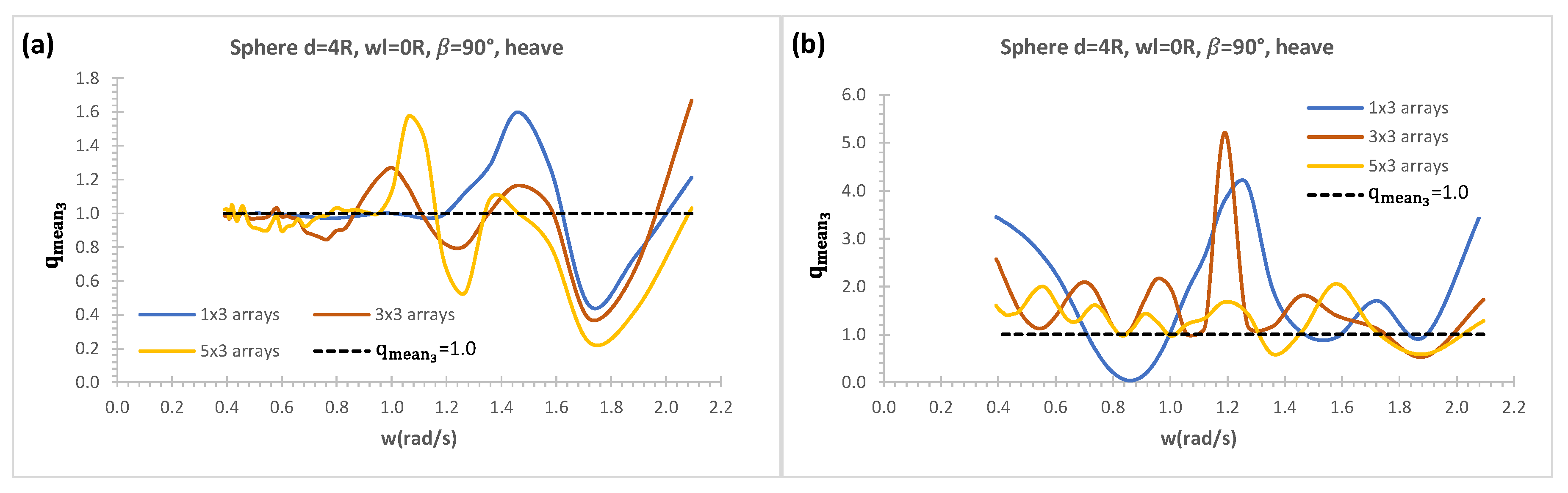
Figure 15(a) and (b) are used to present heave mean interaction factors at heading angle 900 with respect to absolute wave frequencies for 1x3, 3x3, 5x3 arrays keeping column constant and increasing row numbers without and with the effects of a vertical wall respectively. Sphere 1x3 array shows significant constructive effect around absolute wave frequencies of 1.2-1.6 rad/s compared to other configurations in Figure 15(a) in the case of without a vertical wall effect. Mean interaction factor oscillates around 1 up to 1.2 rad/s implying wave power absorption with N number of interacted arrays and isolated N number of WEC are approximately the same. When the row numbers are increased keeping column number constant, there are mixed of constructive and destructive effects with 3x3 arrays as the constructive effect are dominant at lower incident wave frequencies which has more wave power to be absorbed with WECs. It can be observed that 5x3 arrays do not show constructive effect with respect to absolute wave frequencies after absolute wave frequency of 1.1 rad/s in Figure 15(a) although it has considerably high constructive effects at lower wave frequencies. The effects of a vertical wall on all array configurations show dominant constructive effects with respect to absolute wave frequencies in Figure 15(b). The arrays of 1x3, 3x3 in Figure 15(b) show considerably higher constructive effects around 1.2 rad/s and mean interaction factor reaches up to between 4 and 5 whilst 5x3 array also has significant constructive effect in a range of incident wave frequencies. However, when the row numbers are increased, although arrays show the constructive effect, the magnitude of mean interaction factors are considerably reduced (e.g., 5x3 arrays) in Figure 15(b). When mean interaction factor without and with the influence of a vertical wall in Figure 15(a) and (b) are compared, the constructive effects due to a vertical breakwater effect show significantly higher superiority over without a vertical effect with respect to absolute wave frequencies especially lower and mid-range of absolute wave frequencies.
5. Conclusions
The transient in-house computational tool ITU-WAVE, which has a wide range of applications for wave-multibody interactions of floating systems of rigid and elastic isolated or array configurations, are used to predict absorbed wave power with and without a vertical wall effect to determine the behaviors of WECs in an array system. The radiation and exciting IRFs, which are directly calculated in time domain with the time marching of boundary integral equation method and method of images, are used to approximate the absorbed wave power due to the superpositions of wave power from the radiation and exciting forces.
The absorbed wave power is significantly improved and increased with effects of a vertical wall which enhances the absorption considerably. The enhancements of wave power absorption results from the wave motion, standing waves, and nearly trapped waves between WECs arrays and a vertical wall as well as between WECs in an array system. The numerical analyses have shown that the influence of a vertical wall increases the wave power absorption considerably which approximately 2.5 times greater than those of without vertical wall effect at around absolute wave frequency of 1.2 rad/s. In addition, the constructive effects are dominant at lower and mid-range of the incident wave frequencies.
The numerical results of present in-house ITU-WAVE are validated against analytical and other numerical results for interaction and diagonal added mass, and damping coefficients with 1x5 WECs arrays of truncated vertical cylinder, exciting force amplitudes with 2x2 WECs arrays of truncated vertical cylinder, and mean interaction factor with 2x5 WECs arrays of vertical cylinder with hemisphere bottom. The comparison of the present numerical results of ITU-WAVE with analytical and other numerical results show satisfactory agreements.
References
- Budal, K. Theory for absorption of wave power by a system of interacting bodies. J. Ship Res. 1977, 21, 248–253. [Google Scholar] [CrossRef]
- Budal K, Falnes J. Optimum operation of wave power converter. Internal Report, Norwegian University of Science and Technology, 1976.
- Chang MS. Computation of Three-Dimensional Ship Motions with Forward Speed. Proceedings of the 2nd International Symposium on Numerical Ship Hydrodynamics, University of California, Berkeley, 1977; pp. 124-135.
- Chatjigeorgiou, IK. Semi-analytical solution for the water wave diffraction by arrays of truncated circular cylinders in front of a vertical wall. Appl. Ocean Res. 2019, 88, 147–159. [Google Scholar] [CrossRef]
- Cummins, WE. The Impulse response function and ship motions. Shiffstechnik 1962, 9, 101–109. [Google Scholar]
- Evans, DV. A note on the total reflection or transmission of surface waves in the presence of parallel obstacles. J. Fluid Mech. 1975, 67, 465–472. [Google Scholar] [CrossRef]
- Hess, JL; Smith, AMO. Calculation of non-lifting potential flow about arbitrary three-dimensional bodies. J. Ship Res. 1964, 8, 22–44. [Google Scholar] [CrossRef]
- Kagemoto, H; Yue, DKP. Interactions among multiple three-dimensional bodies in water waves: an exact algebraic method. J. Fluid Mech. 1986, 166, 189–209. [Google Scholar] [CrossRef]
- Kara, F. Time domain potential and source methods and their application to twin-hull high speed crafts. Ships Offshore Struct. 2023, 18, 191–204. [Google Scholar] [CrossRef]
- Kara, F. Effects of a vertical wall on wave power absorption with wave energy converters arrays. Renew. Energy 2022, 196, 812–823. [Google Scholar] [CrossRef]
- Kara, F. Application of time domain methods for marine hydrodynamic and hydroelasticity analyses of floating systems. Ships Offshore Struct. 2022, 17, 1628–1645. [Google Scholar] [CrossRef]
- Kara, F. Hydrodynamic performances of wave energy converters arrays in front of a vertical wall. Ocean Eng. 2021, 235, 109459. [Google Scholar] [CrossRef]
- Kara, F. Multibody interactions of floating bodies with time domain predictions. J. Waterw. Port Coast. Ocean Eng. 2020, 146, 04020031. [Google Scholar] [CrossRef]
- Kara, F. Time domain prediction of power absorption from ocean waves with wave energy converters arrays. Renew. Energy 2016, 92, 30–46. [Google Scholar] [CrossRef]
- Kara, F. Time domain prediction of seakeeping behaviour of catamarans. Int. Shipbuild. Prog. 2016, 62. [Google Scholar] [CrossRef]
- Kara, F. Time domain prediction of hydroelasticity of floating bodies. Appl. Ocean Res. 2015, 51, 1–13. [Google Scholar] [CrossRef]
- Kara, F. Time domain prediction of power absorption from ocean waves with latching control. Renew. Energy 2010, 35, 423–434. [Google Scholar] [CrossRef]
- Kara F. Time domain hydrodynamics and hydroelastics analysis of floating bodies with forward speed. PhD thesis, University of Strathclyde, Glasgow, UK, 2000.
- King BW. Time domain analysis of wave exciting forces on ships and bodies. PhD thesis, The University of Michigan, Ann Arbor, Michigan, USA, 1987.
- Konispoliatis, DN; Mavrakos, SA; Katsaounis, GM. Theoretical evaluation of the hydrodynamic characteristics of arrays of vertical axisymmetric floaters of arbitrary shape in front of a vertical breakwater. J. Mar. Sci. Eng. 2020, 8, 62. [Google Scholar] [CrossRef]
- Kring, DC; Sclavounos, PD. Numerical stability analysis for time-domain ship motion simulations. J. Ship Res. 1995, 39, 313–320. [Google Scholar]
- Liapis, S. Time Domain Analysis of Ship Motions. Ph.D. Thesis, The University of Michigan, Ann Arbor, MI, USA, 1986. [Google Scholar]
- Loukogeorgaki, E; Boufidi, I; Chatjigeorgiou, IK. Performance of an array of oblate spheroidal heaving wave energy converters in front of a wall. Water 2020, 12, 188. [Google Scholar] [CrossRef]
- McCallum P, Venugopal V, Forehand D, Sykes R. On the performance of an array of floating wave energy converters for different water depths. In Proceedings of the ASME, 33rd International Conference on Ocean, Offshore and Arctic Engineering, 8–13 June 2014, OMEA2014, USA.
- Mustapa, MA; Yaakob, OB; Ahmed, YM; Rheem, C.-K.; Koh, KK; Adnan, FA. Wave energy device and breakwater integration: A review. Renew. Sustain. Energy Rev. 2017, 77, 43–58. [Google Scholar] [CrossRef]
- Nakos D, Kring D, Sclavounos PD. Rankine Panel Method for Transient Free Surface Flows. Proceedings of the 6th International Symposium on Numerical Hydrodynamics, Iowa City, I.A., USA, 1993, 613-632.
- Newman, JN. Interactions of water waves with two closely spaced vertical obstacles. J. Fluid Mech. 1974, 66, 97–106. [Google Scholar] [CrossRef]
- Newman JN. Channel wall effects in radiation-diffraction analysis, 31st International Workshop on Water Waves and Floating Bodies, 2016.
- Ning, DZ; Zhao, XL; Goteman, M; Kang, HG. Hydrodynamic performance of a pile-restrained WEC-type floating breakwater: an experimental study. Renew Energy 2016, 95, 531–541. [Google Scholar] [CrossRef]
- Ogilvie TF. Recent progress toward the understanding and prediction of ship motions. Proceedings of the 5th Symposium on Naval Hydrodynamics, Office of Naval Research, Washington, D.C., USA, 1964, 3-128.
- Ohkusu, M. Wave action on groups of vertical circular cylinders. J. Soc. Nav. Archit. Jpn. 1972, 131. [Google Scholar] [CrossRef]
- Schay J, Bhattacharjee J, Soares CG. Numerical Modelling of a Heaving Point Absorber in front of a Vertical Wall. In Proceedings of the ASME 32nd International Conference on Ocean, Offshore and Arctic Engineering, Nantes, France, 9–14 June 2013.
- Thomas, GP; Evans, DV. Arrays of three-dimensional wave-energy absorbers. J. Fluid Mech. 1981, 108, 67–88. [Google Scholar] [CrossRef]
- Wehausen JV, Laitone EV. Surface Waves in Fluid Dynamics III in Handbuch der Physik; 1960; Chapter 3, pp. 446–778.
- Zhao, XL; Ning, DZ; Liang, DF. Experimental investigation on hydrodynamic performance of a breakwater integrated WEC system. Ocean Eng. 2019, 171, 25–32. [Google Scholar] [CrossRef]
Figure 1.
Positions of WECs in 2x5 arrays with a vertical wall (breakwater) and a coordinate system in xy-plane.
Figure 1.
Positions of WECs in 2x5 arrays with a vertical wall (breakwater) and a coordinate system in xy-plane.
Figure 2.
Nondimensional interaction sway radiation force coefficients between WEC1 and WEC4; (a) ; (b) .
Figure 2.
Nondimensional interaction sway radiation force coefficients between WEC1 and WEC4; (a) ; (b) .
Figure 3.
Nondimensional interaction sway radiation force coefficients between WEC1 and WEC5; (a) ; (b) .
Figure 3.
Nondimensional interaction sway radiation force coefficients between WEC1 and WEC5; (a) ; (b) .
Figure 4.
Nondimensional amplitudes of exciting forces in surge mode; (a) ; (b) .
Figure 5.
Mean interaction factor of rectangle 2x5 arrays.
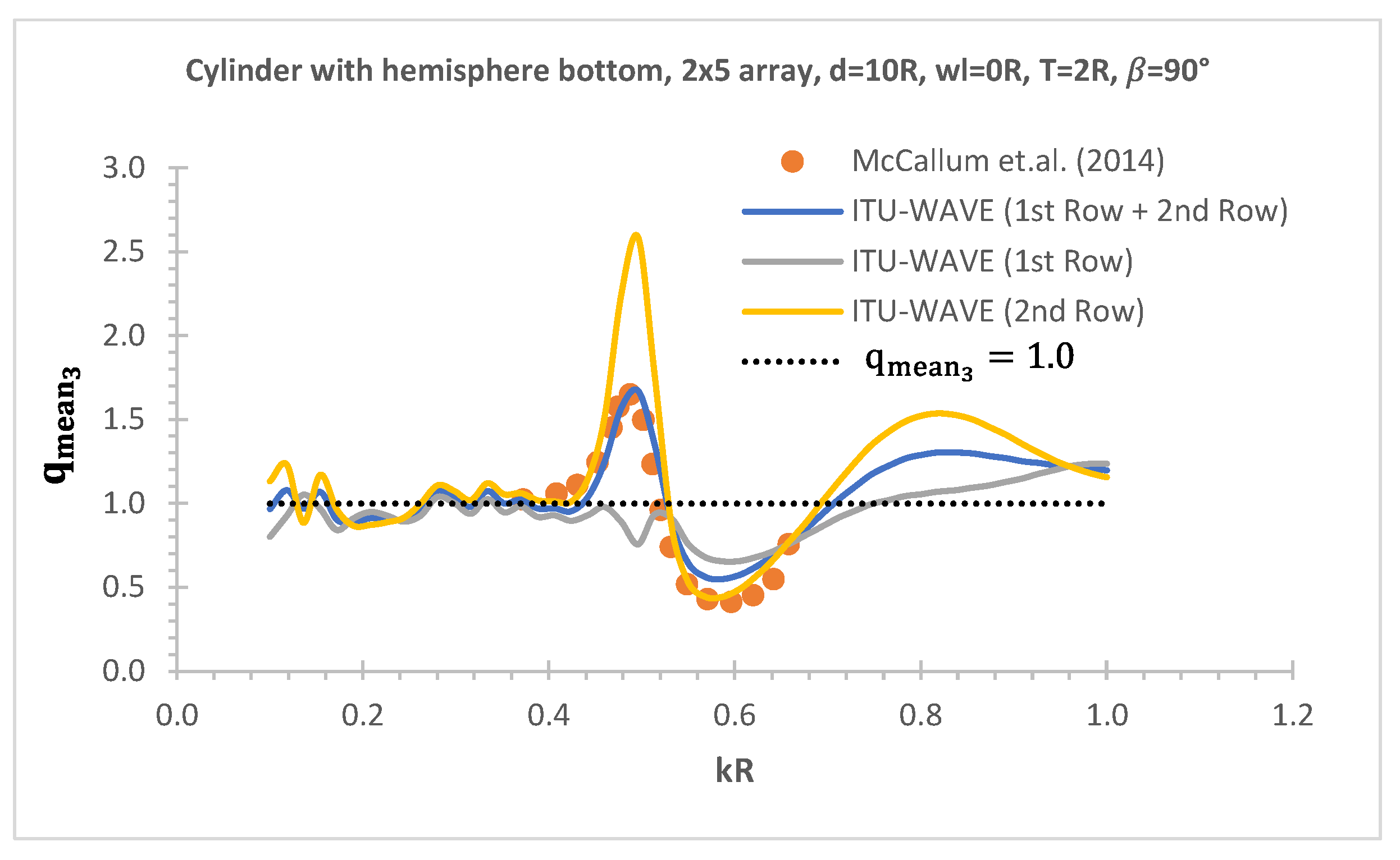
Figure 6.
Nondimensional heave IRF of exciting force for 5th row of 5x5 arrays with and without a vertical wall effect.
Figure 6.
Nondimensional heave IRF of exciting force for 5th row of 5x5 arrays with and without a vertical wall effect.
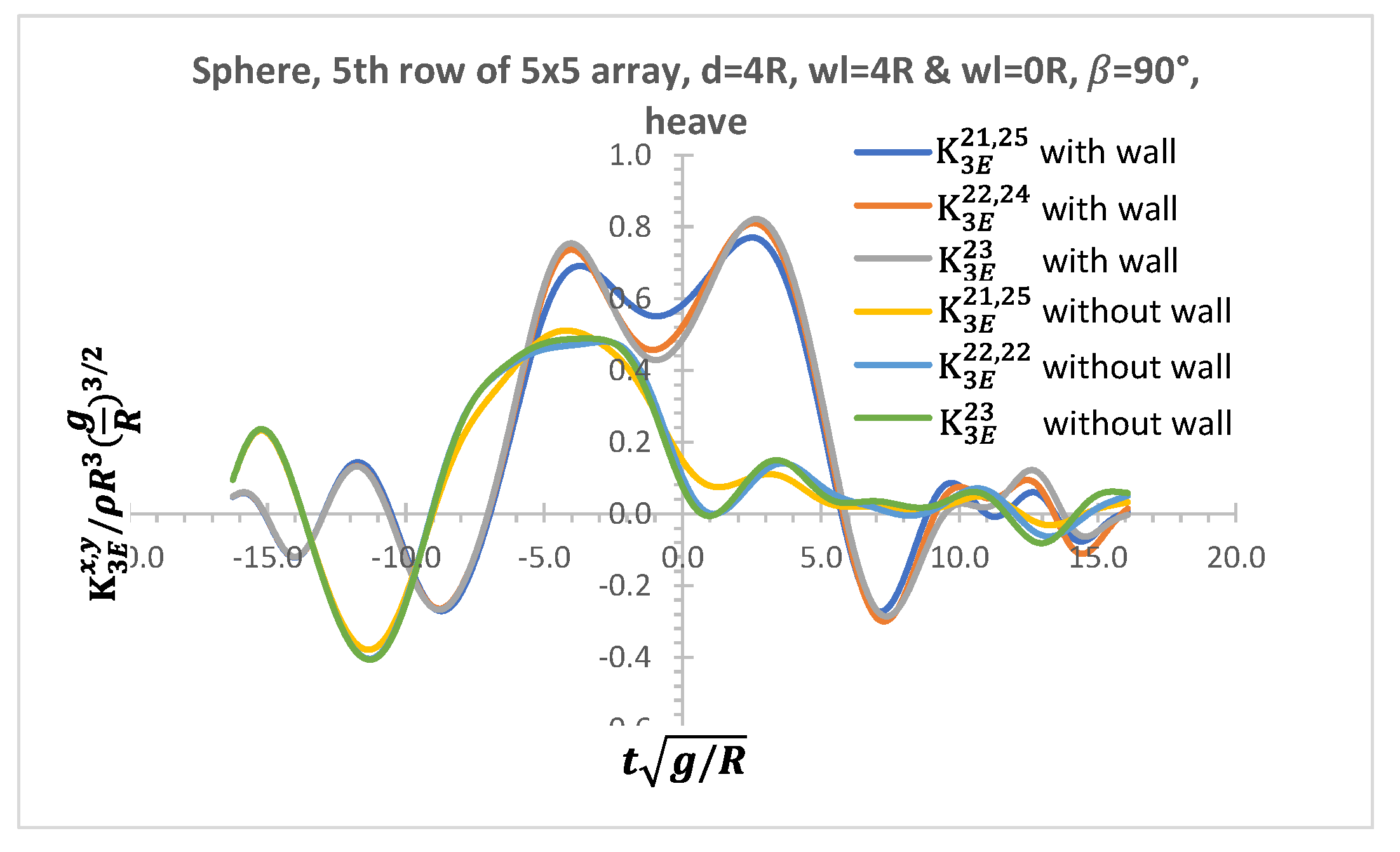
Figure 7.
Nondimensional IRFs of exciting force in heave mode at the center of each row of 3x5 arrays; (a) without a vertical breakwater; (b) with a vertical breakwater.
Figure 7.
Nondimensional IRFs of exciting force in heave mode at the center of each row of 3x5 arrays; (a) without a vertical breakwater; (b) with a vertical breakwater.
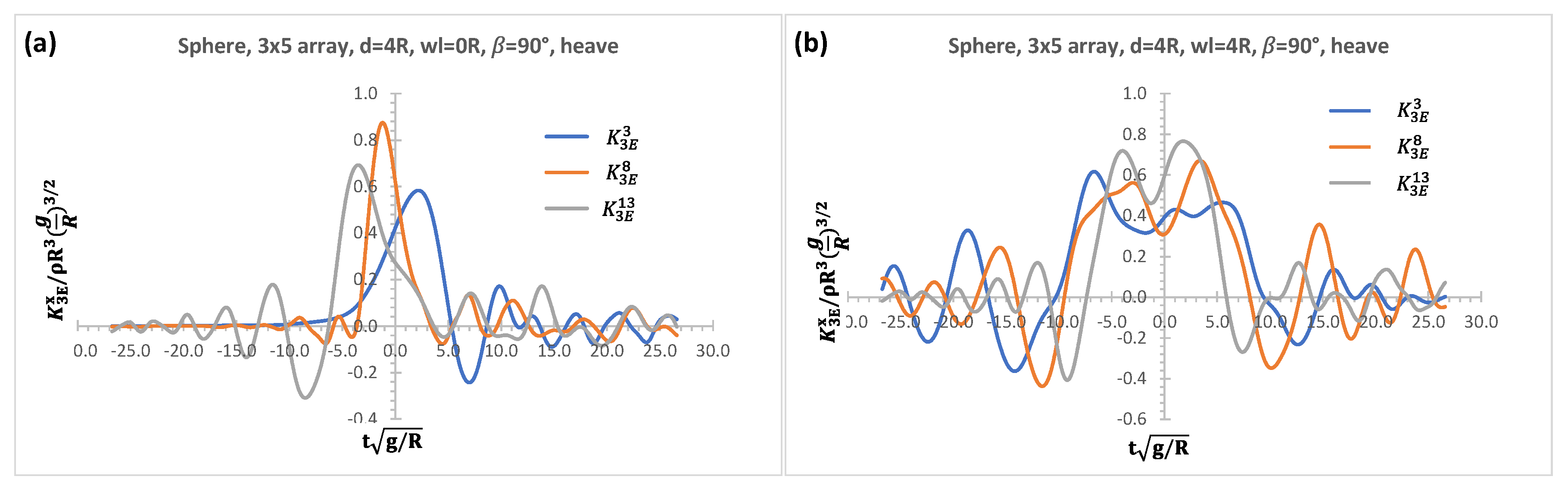
Figure 8.
Nondimensional heave radiation interaction IRFs of 3x5 arrays; (a) without a vertical wall; (b) with a vertical wall.
Figure 8.
Nondimensional heave radiation interaction IRFs of 3x5 arrays; (a) without a vertical wall; (b) with a vertical wall.
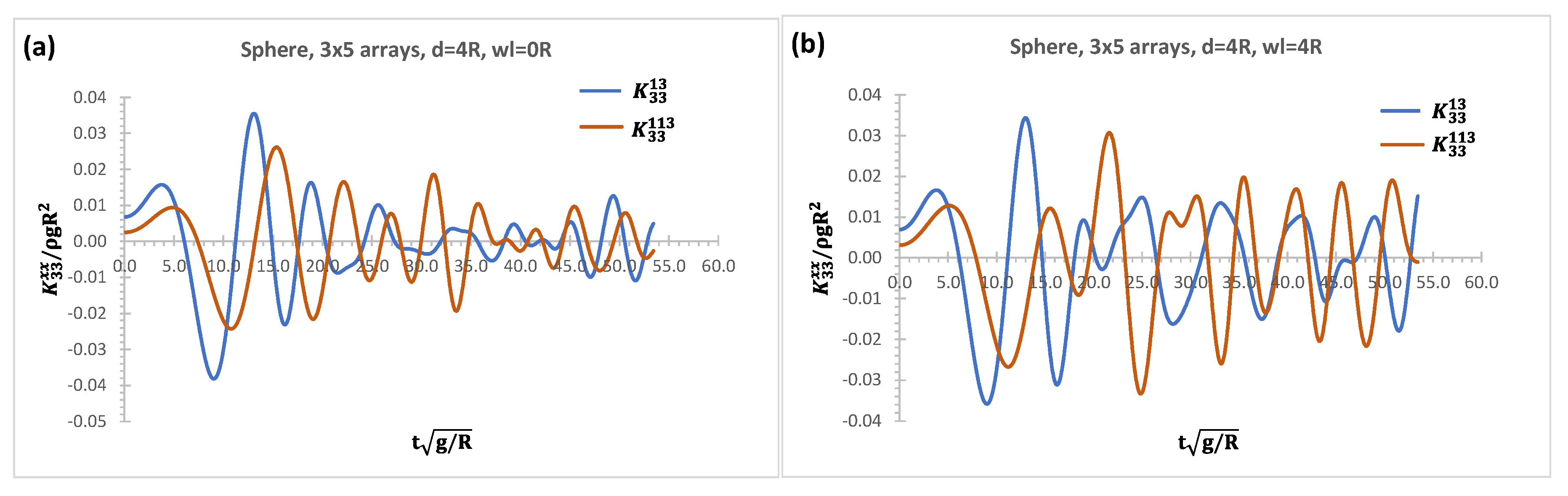
Figure 9.
Effects of a vertical wall on each WEC’s RAO for 1x3 arrays of sphere; (a) sway; (b) heave.
Figure 9.
Effects of a vertical wall on each WEC’s RAO for 1x3 arrays of sphere; (a) sway; (b) heave.
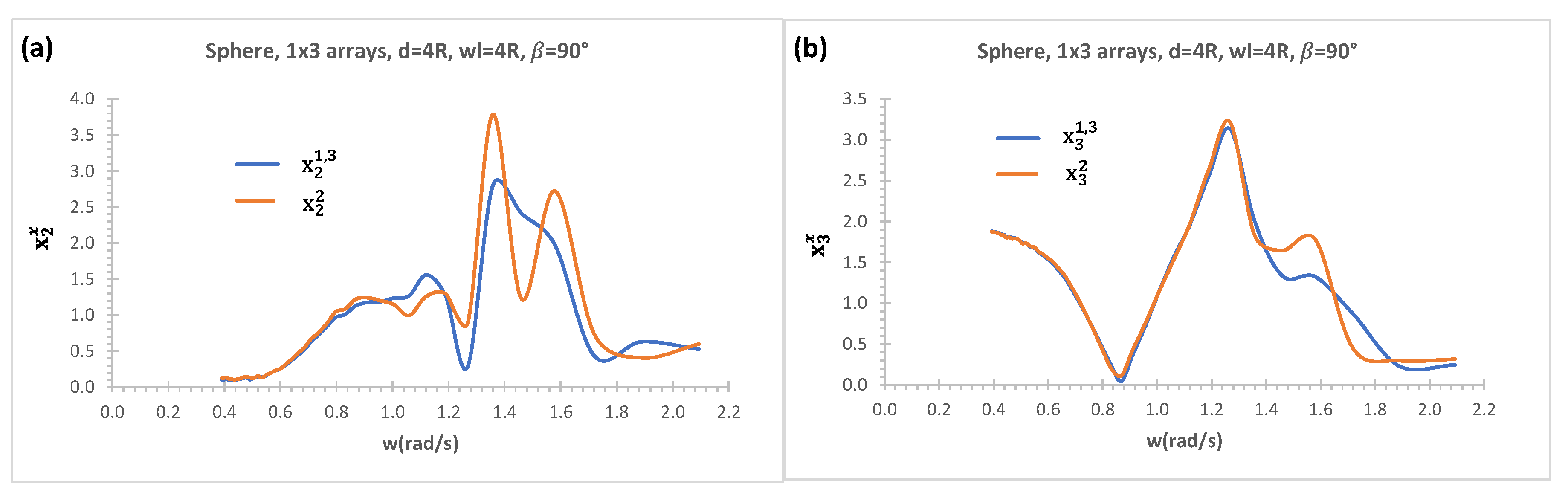
Figure 10.
Effects of a vertical wall on each WEC’s RAO for 2x3 arrays of sphere; (a) 1st row sway; (b) 2nd row sway; (c) 1st row heave; (d) 2nd row heave.
Figure 10.
Effects of a vertical wall on each WEC’s RAO for 2x3 arrays of sphere; (a) 1st row sway; (b) 2nd row sway; (c) 1st row heave; (d) 2nd row heave.
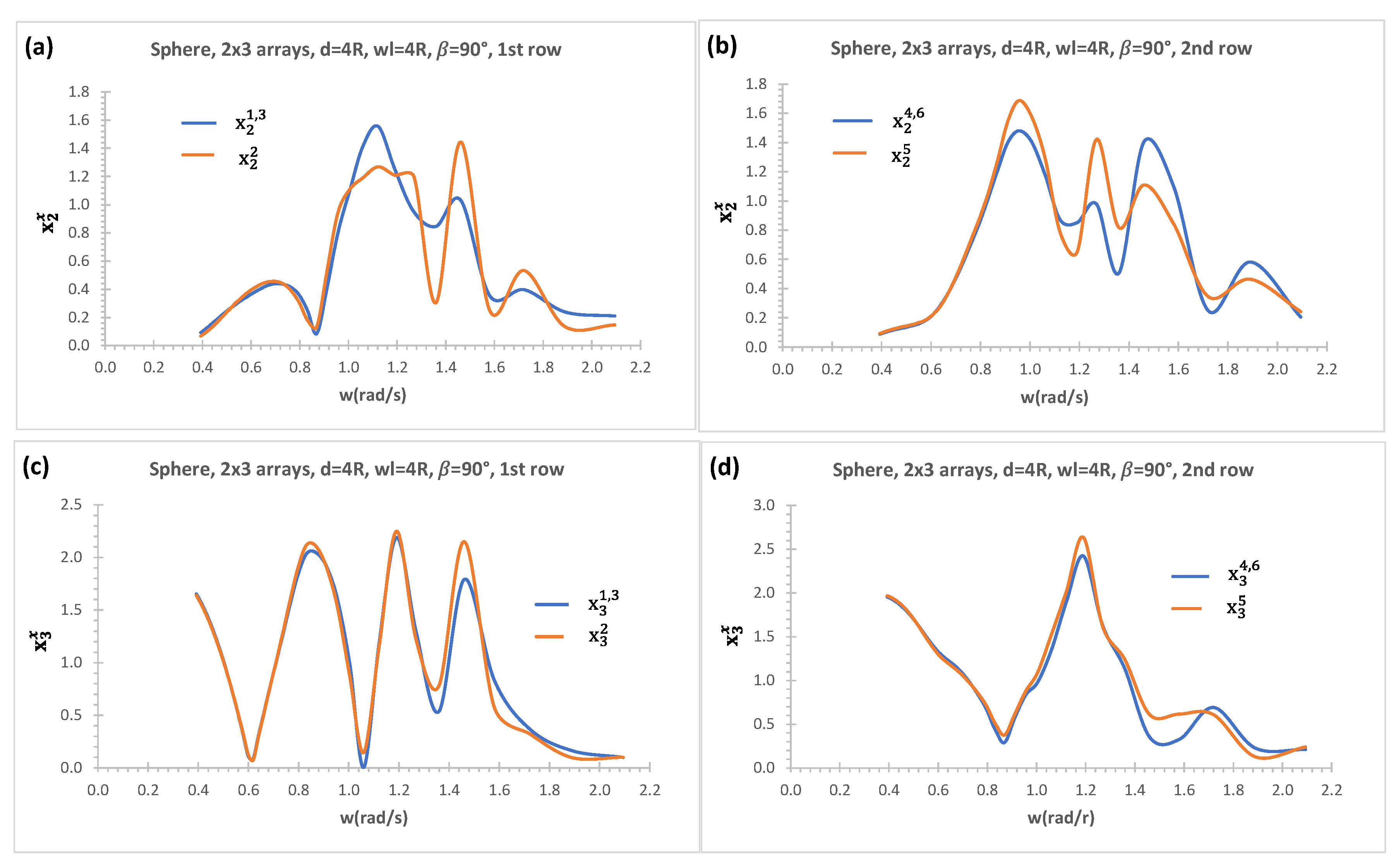
Figure 11.
Heave and sway modes of isolated sphere; (a) , ; (b) .

Figure 12.
Effects of a vertical wall with 2x3 arrays on wave power absorption; (a) (b) .
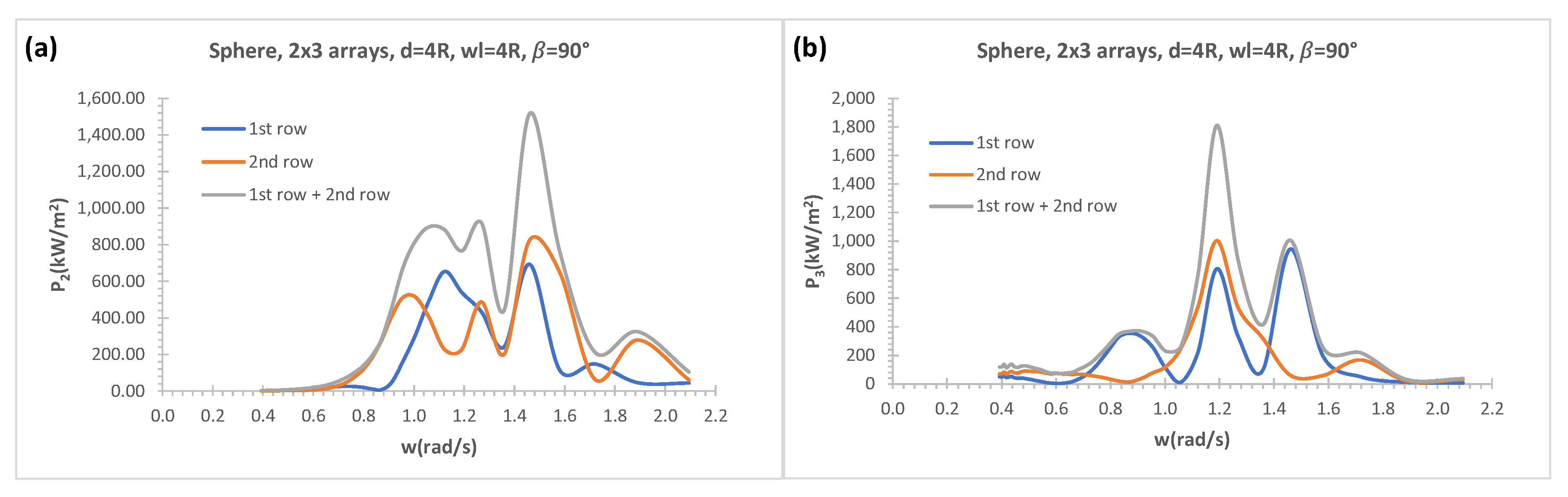
Figure 13.
Heave mean interaction factors of each row without a vertical wall effect; (a) 2x3; (b) 3x3 arrays.
Figure 13.
Heave mean interaction factors of each row without a vertical wall effect; (a) 2x3; (b) 3x3 arrays.
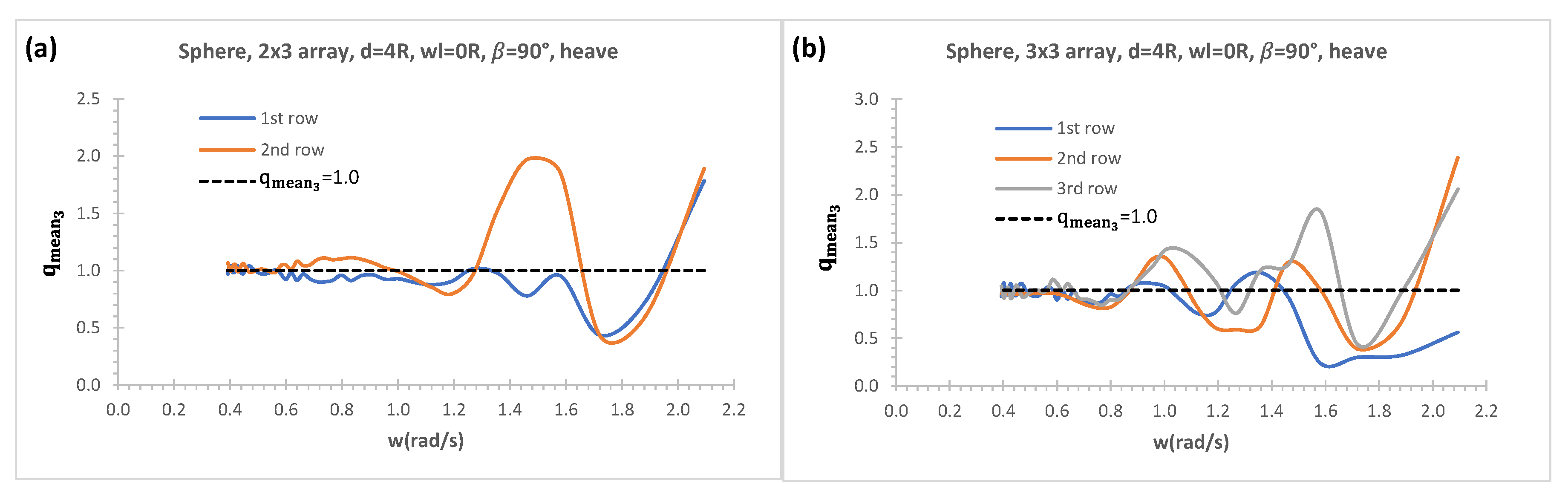
Figure 14.
Effects of a vertical wall on heave mean interaction factors of each row; (a) 2x3 arrays; (b) 3x3 arrays.
Figure 14.
Effects of a vertical wall on heave mean interaction factors of each row; (a) 2x3 arrays; (b) 3x3 arrays.
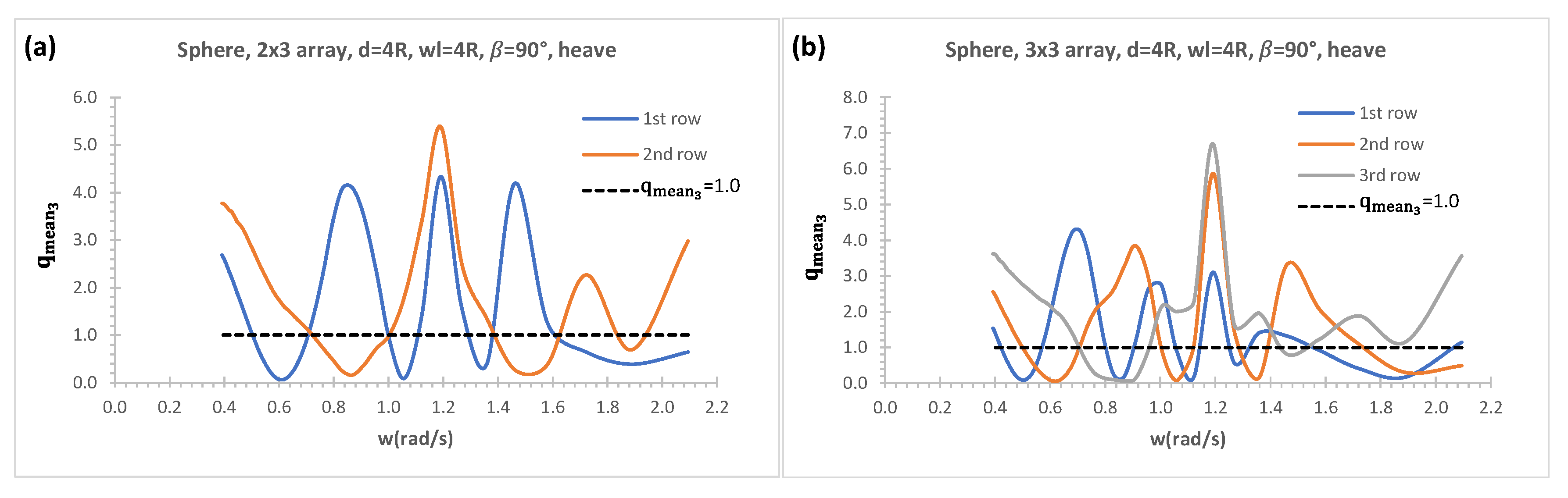
Figure 15.
Heave mean interaction factors in a range of row numbers; (a) without a vertical wall; (b) with a vertical wall.
Figure 15.
Heave mean interaction factors in a range of row numbers; (a) without a vertical wall; (b) with a vertical wall.
Disclaimer/Publisher’s Note: The statements, opinions and data contained in all publications are solely those of the individual author(s) and contributor(s) and not of MDPI and/or the editor(s). MDPI and/or the editor(s) disclaim responsibility for any injury to people or property resulting from any ideas, methods, instructions or products referred to in the content. |
© 2024 by the authors. Licensee MDPI, Basel, Switzerland. This article is an open access article distributed under the terms and conditions of the Creative Commons Attribution (CC BY) license (http://creativecommons.org/licenses/by/4.0/).
Copyright: This open access article is published under a Creative Commons CC BY 4.0 license, which permit the free download, distribution, and reuse, provided that the author and preprint are cited in any reuse.


