1. Introduction
Short-arc xenon discharges at high pressure are used as a source of optical radiation when the emission spectrum has to be as close to the diffuse sky radiation as possible and when it is necessary to have high intensity radiation of a point source of light. These lamps produce a bright white light with applications in movie projectors in theaters, in searchlights, and for specialized uses in industry. Xenon lamps are also widely used in scientific research. They can take the form of flash lamps (pulsed) or continuous-action lamps (DC). One of the main advantages of xenon flash lamps is their ability to provide high optical light energy in a short pulse (a few microseconds), producing high peak power. Due to their broad and continuous spectra (200nm–2.5μm), xenon lamps can be used for laser light pumping, absorbance measurements, scattering, medical purposes and more. Xenon lamps can also be used for illumination, whether for scientific microscopy or cameras. The typical discharge conditions of short-arc xenon lamps are as follows: xenon pressure up to 3.000 kPa (~30 atm.), electric power up to 15kW (electric current up to several hundred A), and the distance between electrodes of several mm.
High-pressure discharges in rare gases (Ar, Kr, Xe), which are widely used for developing sources of intensive optical radiation, are rather well understood (see e.g., [
1,
2]). However, a number of problems remain unexplored. The high discharge current density and a considerable heating of the discharge electrodes raise the question of the possible presence of electrode material atoms, especially cathode atoms, in the discharge gap. These atoms usually have a lower ionization potential in comparison with xenon (or other rare gases) and hence can affect the discharge properties, at first, the ionization balance. A very interesting result was obtained in [
3], where by doping a discharge with metal halide such as thallium iodide the spectral radiant intensity per unit area in the plasma zone immediately in front of the cathode was substantially increased compared with an undoped xenon short-arc discharge lamp. It showed that the presence of atoms with low ionization and excitation potentials noticeably changed the plasma properties near the cathode and improved the plasma emission characteristics. Xenon light sources of high pressure generally have thoriated tungsten cathodes to increase electron emission. A high cathode temperature could lead to thorium atom evaporation into the discharge gap and due to the low ionization energy of thorium atoms (~6ev) compared to xenon atoms (~12.1ev) the process could produce an effect similar to that of [
3]. There exists a wide range of experimental and calculated data about cathode surface temperature. The temperatures obtained vary from 3,000K [
4,
5,
6] to approximately 4,000K [
7,
8,
9,
10,
11,
12]. The result [
13] for a high-pressure Xe discharge with a conical cathode shape and 2% ThO
2 doping shows the cathode temperature of 3,631K. Based on the temperature dependence of thorium saturated vapor pressure [
14] one can conclude that the cathode tip temperature of about 3,600K provides thorium atom concentration ≥10
23m
−3. This value is comparable to the expected electron concentration in the plasma [
9,
10,
11,
12,
13,
14,
15], so we suppose that this concentration is sufficiently high to have a strong influence on the near-cathode plasma.
The possible presence of cathode atoms in the discharge volume was also mentioned in [
16], but was not analyzed in detail. Similar effects were also studied in [
17,
18], where the effect of barium transport on the operation of dispenser hollow cathodes discharge was investigated in numerical modeling of a cathode with orifice.
The effect of the discharge electrode surface on the plasma properties is very interesting question that has not been studied in detail so far. The plasma characteristics are primarily determined by the electric field strength E in the discharge gap. The electric field determines the heat of a plasma. The surfaces of discharge electrodes are equipotential, the potential difference between them being equal to the voltage applied to the discharge. Changing the shape of the anode and/or cathode surface necessarily changes the spatial distribution of the electric field in the discharge volume. The shape of the cathode surface can also have a pronounced effect: changing the cathode cone angle can strongly affect the strength of the electric field near the cathode, the spatial distribution of E in the adjacent plasma region and, consequently, other plasma characteristics.
We were not successful in finding previously carried out researches of the electrode surface shape influence on the discharge plasma characteristics. We found only some patents concerning the modification of the anode working surface shape (anode form) with general purposes to diminish anode heat load or to make discharge operation more stable and an article describing the study of Hg-discharge with different electrodes shapes.
A special shape of an anode working surface for a short arc discharge lamp is described in [
19]. The anode has an anode-inner wall surface formed by an anode tip end surface that is inwardly caved in a circumferential direction. This cavity increases the working surface of the anode, which reduces thermal load on the anode and, therefore, evaporation of anode material and the blackening of discharge tube walls. Another construction of an anode is presented in [
20]. The purpose of the invention is the same. The anode has a concave portion, which is formed on the central axis of anode tip surface. To provide a discharge lamp obtaining a higher illuminance maintenance rate while obtaining a brightness equivalent to that of the conventional discharge lamp, the anode is formed with a recess in a shape of a spherical surface on the centerline of the anode on a tip face of the anode [
21]. A similar anode surface form is used in [
22] to provide a short arc discharge lamp for improving utilization efficiency of light by actively utilizing light radiated from the cathode tip to the tip surface of an anode. As in [
21] the anode includes a recessed spherical part formed on an end facing to the cathode.
The subject of [
23] is the modeling of DC and AC high-intensity Hg-discharge lamps with differently shaped electrodes. Modeling results for a 0.6MPa mercury discharge considering six different electrode shapes (anode and cathode) are presented and compared with experimental results. The electrodes have different diameters and different electrode tips, such as hemispherical, flat, or conical tip with 60° or 90° apex angle (concave shapes were not considered). An important result is that the shape of the electrode tip influences the lamp characteristics essentially.
Note that mentioned above researches did not take into account possible presence of electrodes material in the plasma and hence their influence on plasma properties. The effect of electrodes shape has also not been analyzed in detail. In our opinion, this did not allow for a proper explanation of the results obtained.
An earlier analysis of the radiation spectrum along the axis of the high-pressure short-arc xenon discharge [
24] led to results that could not be explained disregarding the emission of thorium in the discharge gap: when evaporating into the plasma volume thorium atoms decreased the plasma temperature near the cathode and affected other plasma characteristics.
Modeling of the plasma in question in a simplified geometry, a plane one-dimensional case [
25], really showed a strong influence of thorium atoms on the electrokinetic plasma characteristics near the cathode, while the plasma properties near the anode were wholly determined by xenon.
The present study is aimed at presenting the model of the short-arc xenon discharge plasma at a high pressure in the real geometry (short arc) taking into account the influence of thorium atoms on plasma processes. The developed model makes it possible to study the effect of the electrode surface shape on the plasma electrokinetic and optical characteristics. Anodes of concave and convex shapes and cathodes with different cone angles are examined.
2. Assumptions and basic relations
We assume that the plasma in question is in the local thermodynamic equilibrium (LTE) [
1,
2,
15,
25,
26]. It means that all plasma characteristics, except radiation, are in equilibrium and the following relations are fulfilled: Maxwellian velocity distributions of particles with the same temperature, Boltzmann distributions of excited states, and Saha relation for the density of charged particles. Planck's law for radiation is invalid, as follows from the concept of LTE. The second assumption is that the plasma contains thorium atoms emitted by the thoriated cathode. As the estimate shows, the thickness of the near-electrode layers is significantly small in comparison with the plasma dimension. Realizing that the description of electrode layers is a complex and difficult task, we do not include the description of the electrode layers, as well as the discussion of the electrode operation (spot mode for the cathode and diffusive mode for the anode). We also do not consider a possible impact of the massive cathode and anode on the profiles of the plasma temperature and temperatures of the electrodes themselves.
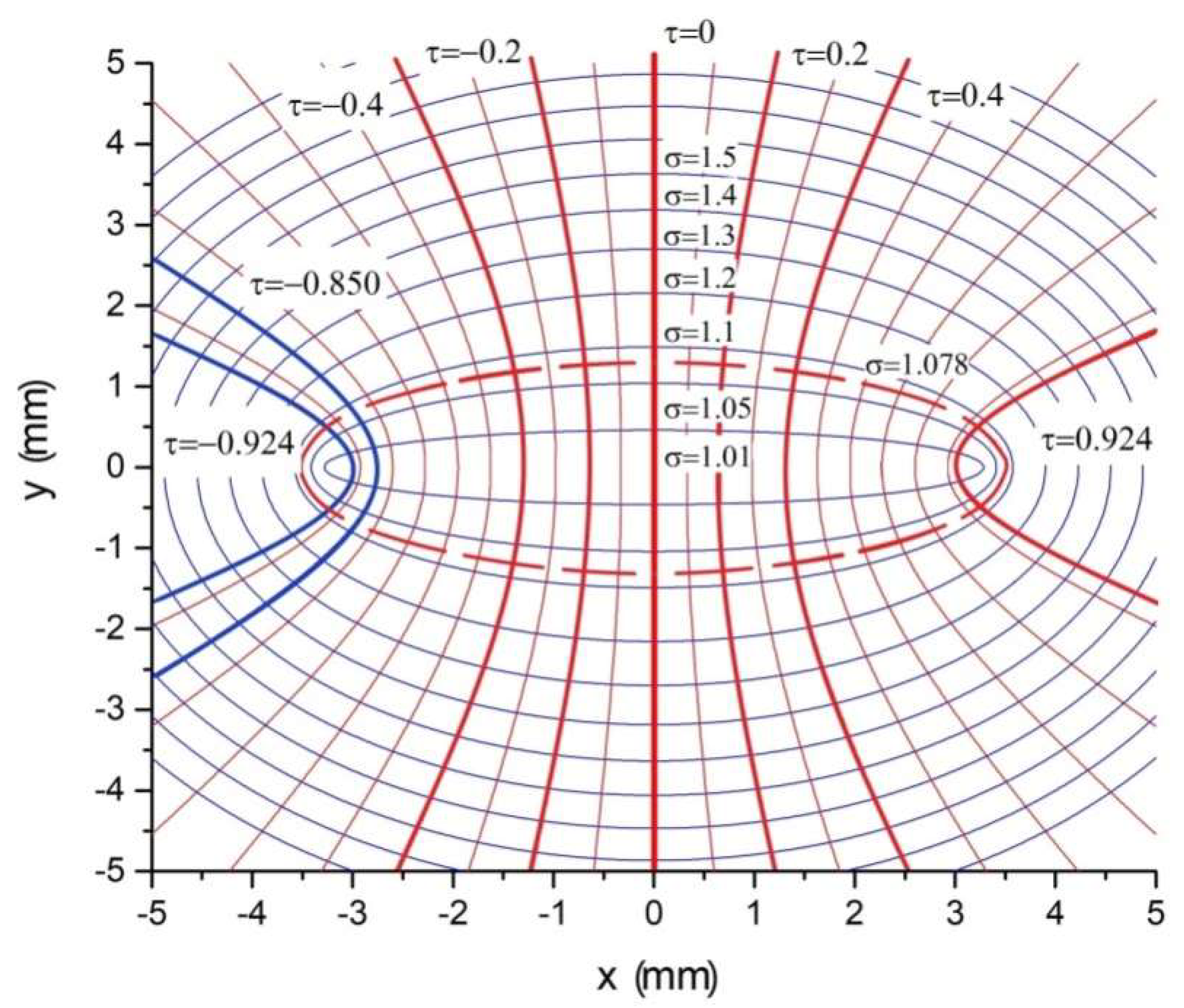
The discharge geometry is such that it is convenient to use the ellipsoidal coordinates (oblong ellipsoid of revolution) [
27] for describing spatial distributions of plasma characteristics. In this representation we suppose that the cathode surface coincides with some surface τ
0, and the anode surface coincides with τ
L, these surfaces being surely equipotential. It can be expected that all other surfaces τ = const are also approximately equipotential. Lines perpendicular to τ surfaces set the direction of the electric field. Such a representation makes it possible to determine straight away the electric current lines.
Figure 1 shows the geometry of the short-arc discharge in question, surfaces of the electrodes and the electric current channel. Two cathode surface shapes, τ
0 = −0.924, −0.850 (blue thick lines), and six anode surface shapes, τ
L = −0.4, −0.2, 0, +0.2, +0.4, +0.924 (red thick lines), are considered. The case τ
L = +0.924 corresponds to the surface of the anode, which is symmetrical to the cathode τ
0 = −0.924. There are practically no thorium atoms near the anode, and plasma is formed as a result of processes involving only xenon atoms and ions. Thus, the case τ
L = +0.924 gives a comparison of the plasma discharge of pure xenon (at the anode) and the plasma with the presence of thorium atoms (at the cathode), since the special distributions of the electric field strength near the cathode and anode are close to it other.
To determine plasma characteristics (temperature T electric field strength E thorium atomic concentration N
Th, and densities of thorium and xenon ions
and
respectively), we formulated five equations: two Saha equations for thorium and xenon ions, the power balance equation, the equation for the electric current through the plasma, and the balance equation for the number of thorium atoms and ions. We do not know the temperature of the cathode hotspot. Based on the data [
4,
5,
6,
7,
8,
9,
10,
11,
12,
13,
14] we assume a gap in the most probable values of the thorium atom concentration
in the range (10
23 − 10
24)m
−3. In fact, we use this concentration as a parameter of our task.
Estimation shows that thermal conductivity do not play a significant role in the plasma energy balance [
28,
29]. It is governed by heating in the electric field and plasma radiation. This is a common phenomenon for light sources, since the radiation must be the main channel to get the output power. The conclusion is confirmed by empirical data on the radiation power of discharges in rare gases [
28]. These data, in particular, show that (85 − 88)% of the total electric power goes to the radiation of Xe arc discharges. We also did not account for thermal diffusion, ambipolar diffusion and convection due to the LTE assumption, which means there are no spatial fluxes. We are aware that convection could play a certain role, however this process proceeds rather slowly and, in our opinion, does not affect the plasma modeling, characteristics of which are determined by faster processes.
The plasma radiation, which we take into account, consists of two parts: 1) recombination-bremsstrahlung radiation, in which recombination prevails over bremsstrahlung for the discharge in question [
28], and 2) emission of xenon spectrum lines (the most intensive lines in the range ~(870 − 1070) nm). Emission in the continuous spectrum is calculated using the data of [
28]; information about the most intensive xenon lines are taken from [
14,
30,
31]. The spectrum lines of thorium, as shown by estimate, do not contribute to the total radiation (note that thorium spectrum lines were not registered in [
24]).
The desired configuration of electrodes is selected by the appropriate choice of the cathode and anode surfaces with the coordinates τ
0 and τ
L. These surface coordinates are included in the coefficients of the solution to the balance equation for the number of thorium atoms and ions, which is described in detail in [
26]. The case of the flat anode is described in [
25].
3. Results of modeling and discussion
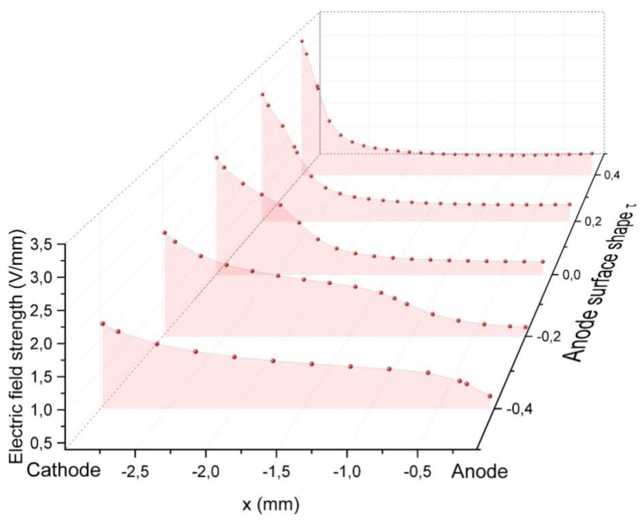
The strength of the electric field on the discharge axis at τ
0 = −0.924 is shown in
Figure 2. The calculations were carried out for different shapes of the anode surface and the same distance between the electrodes L = 3mm. It is seen that the shape of the anode strongly affects the electric field strength E It is approximately twice as high at the cathode for the convex shape with τ
L = +0.4 compared with the concave shape with τ
L = −0.4 The latter configuration shortens the length of the electric field lines, and makes the spatial distribution of the electric field wider.
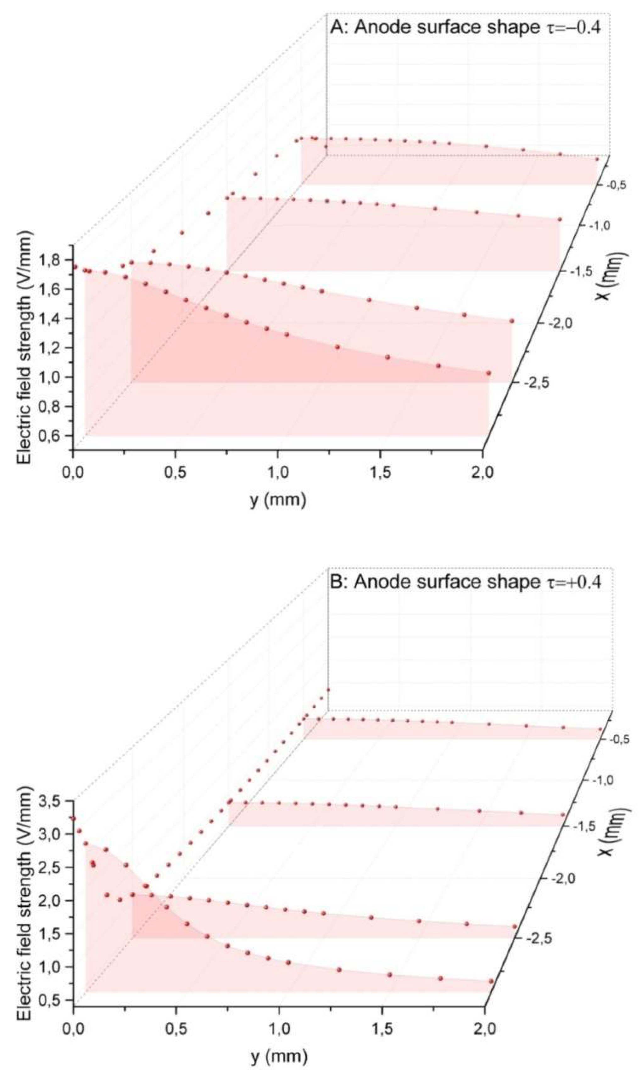
Figure 3 with the results of calculating the dependence of E(y) on the radial Cartesian coordinate y in the discharge volume for two opposite anode shapes τ
L = −0.4 (concave) and τ
L = +0.4 (convex) confirms the conclusion. E(y) is presented for four points on the discharge axis: x = −2.9mm, −2.5mm, −1.5mm, −0.5mm. At τ
L = −0.4 (
Figure 3A) the electric field strength decreases with y noticeably more slowly than with the shape τ
L = +0.4 (
Figure 3B). For example, in the case of the concave anode the twofold drop of E near the cathode (x = −2.9mm) is observed at y > 2.0mm, in the case of the convex anode, at
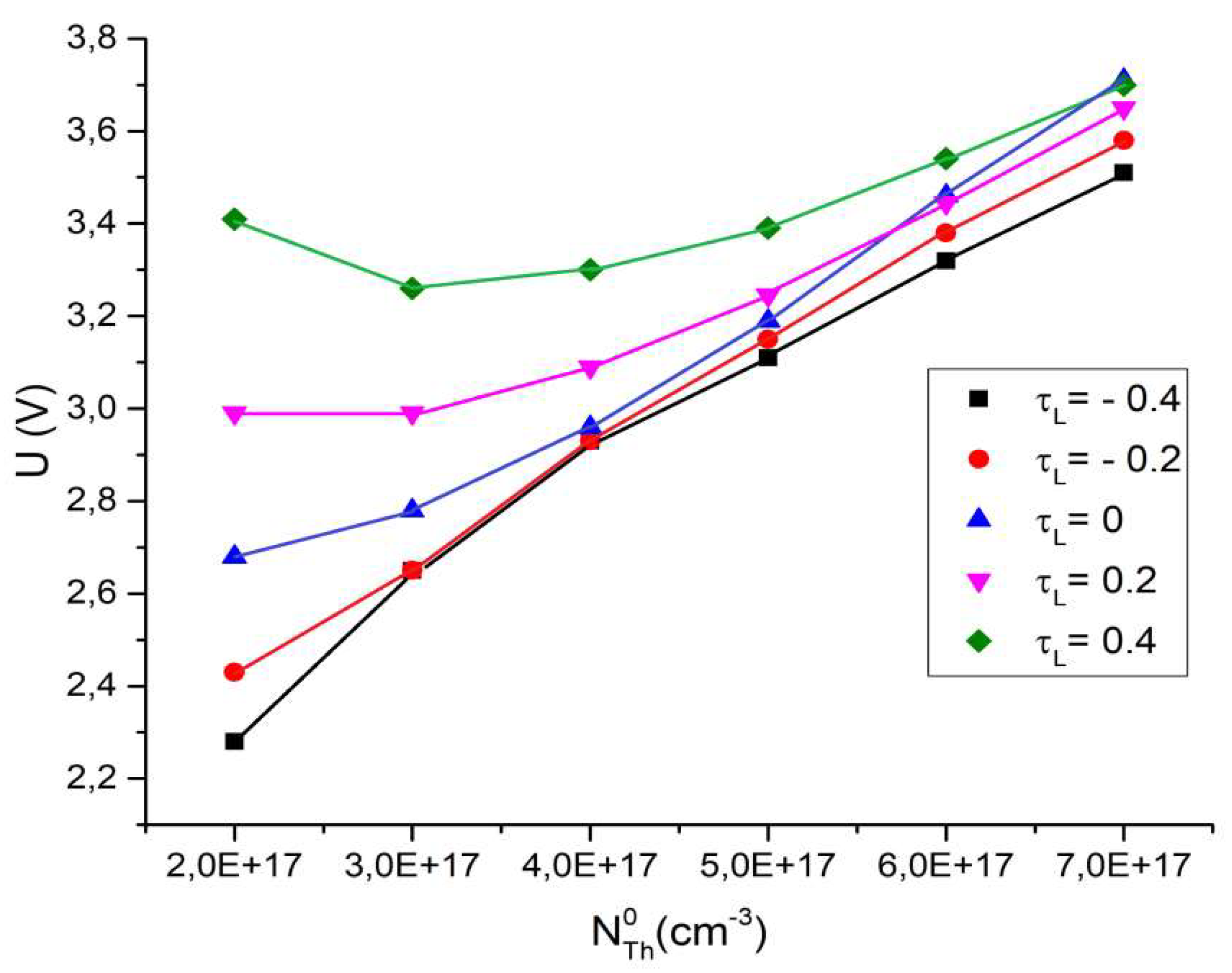
One can argue that a lower value of the electric field strength for the case of a concave anode surface should decrease the voltage at the discharge electrodes. The following
Figure 4 shows the voltage U for a discharge with anodes of different shapes. The concentration of thorium atoms is also varied.
The transition from the convex shape of the anode surface to the concave shape actually reduces the discharge voltage. The difference is more pronounced at a low concentration of thorium atoms; however, an increase in the concentration makes the voltage to be approximately the same for discharges with different anode shapes. The possible reason is a decrease in the electron density with an increase in the thorium content (see [
26]).
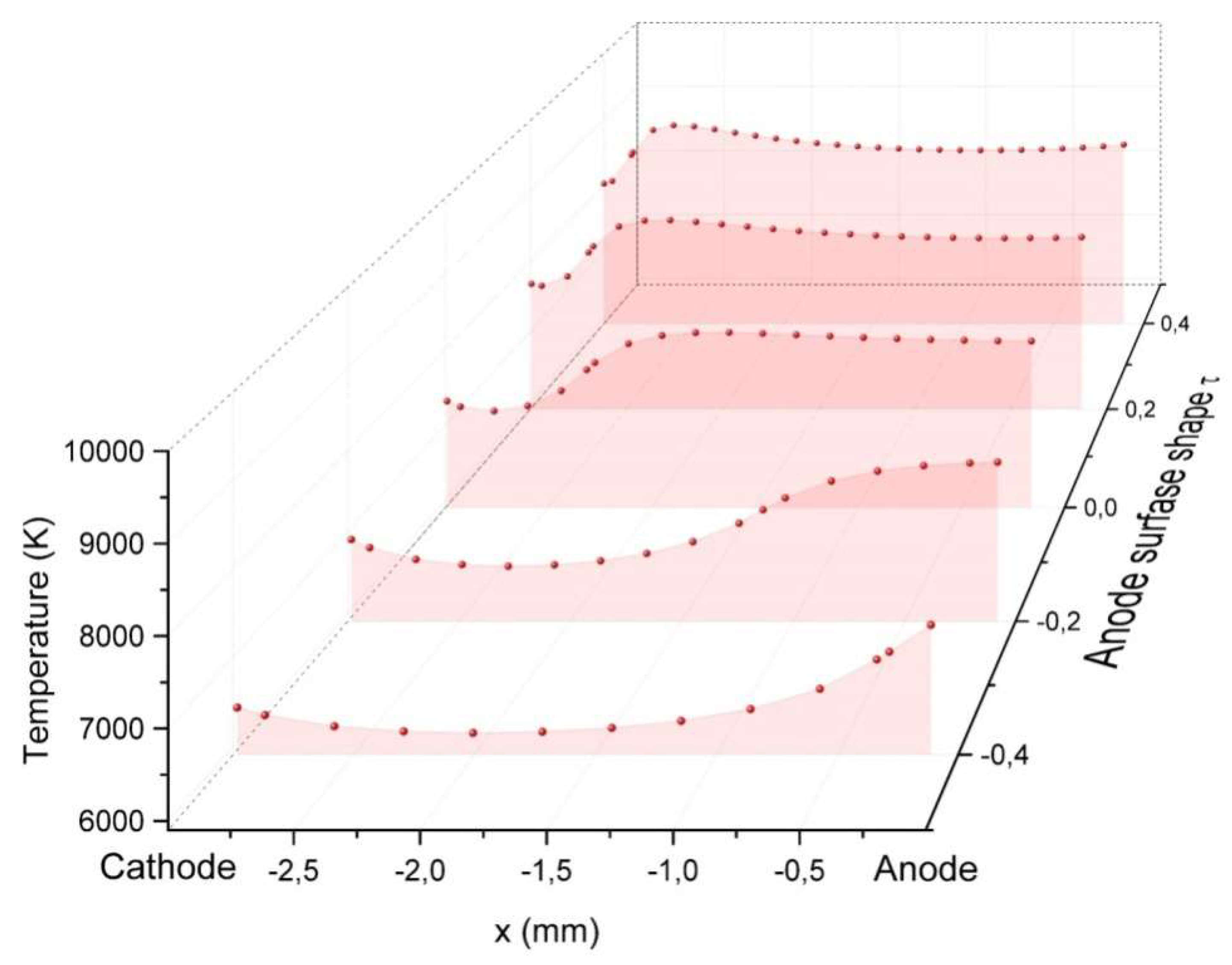
Figure 5 shows the plasma temperature T for the cathode shape τ
0 = −0.924 and five shapes of the anode τ
L = −0.4, −0.2, 0, +0.2, +0.4. It is seen that the shape of the electrodes, strongly affecting E, strongly affects T as well. Calculations show that the effect of the cathode cone angle is quite expected: the smaller the angle, the higher the temperature due to the higher strength of the electric field on the cathode surface. The cathode with τ
0 = −0.850 decreases the plasma temperature near the cathode by (500 − 800)K. At the anode the influence of the cathode cone angle on the plasma temperature is small. The shape of the anode surface also strongly affects T: in comparison with the flat anode, the concave surface of the anode decreases the plasma temperature, while the convex surface increases it. The difference is large and reaches the order of (2,500 – 3,000)K. The case τ
L = +0.4 shows that the temperature at the electrodes reaches a value of (9,300 – 9,500)K; in the middle of the discharge gap it is about 9,000K. The temperature obtained is close to that of a discharge in pure xenon [
28].
The spatial distribution of the electric field strength (
Figure 3) determines the corresponding spatial distribution of the plasma temperature.
Figure 6 shows these data.
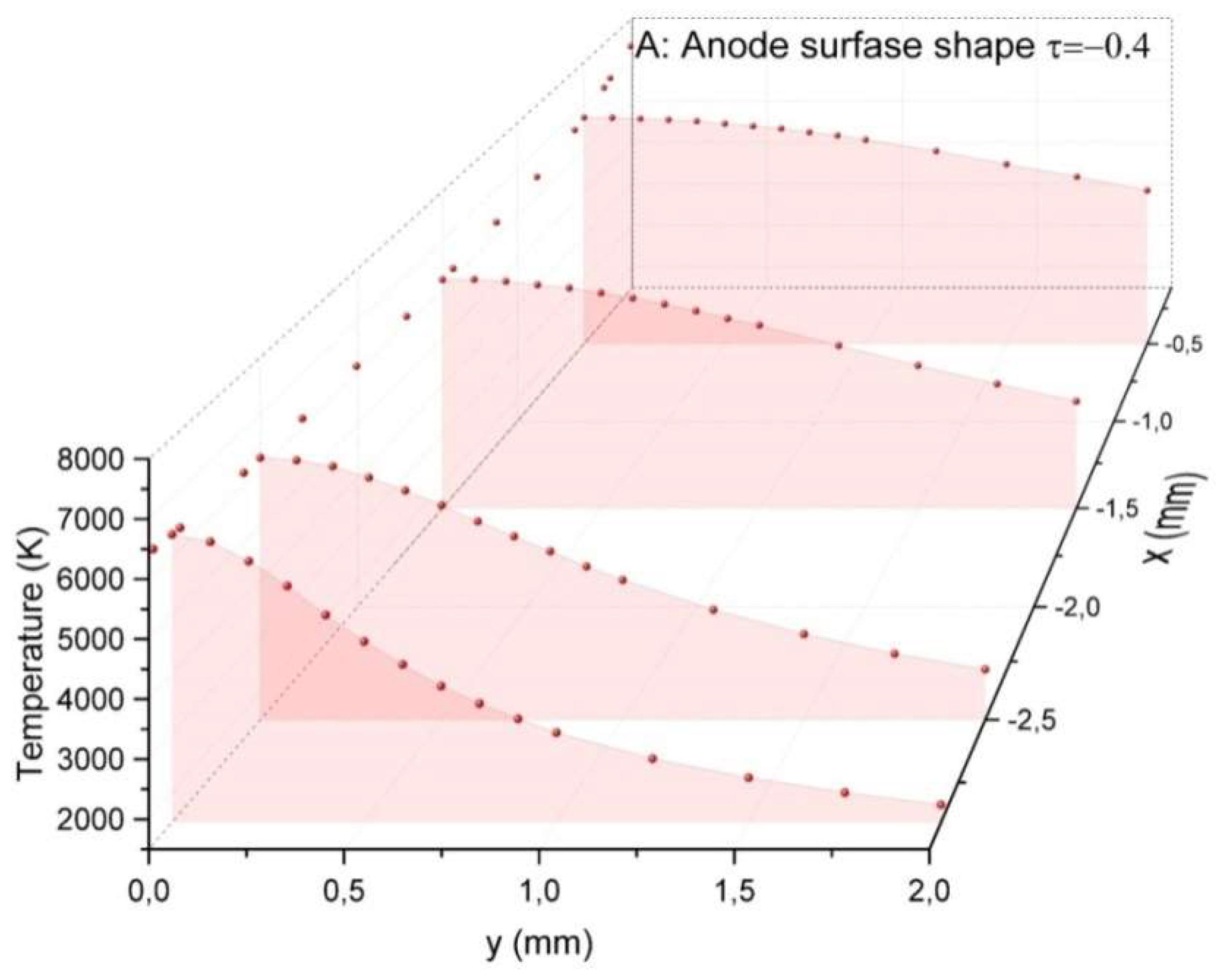
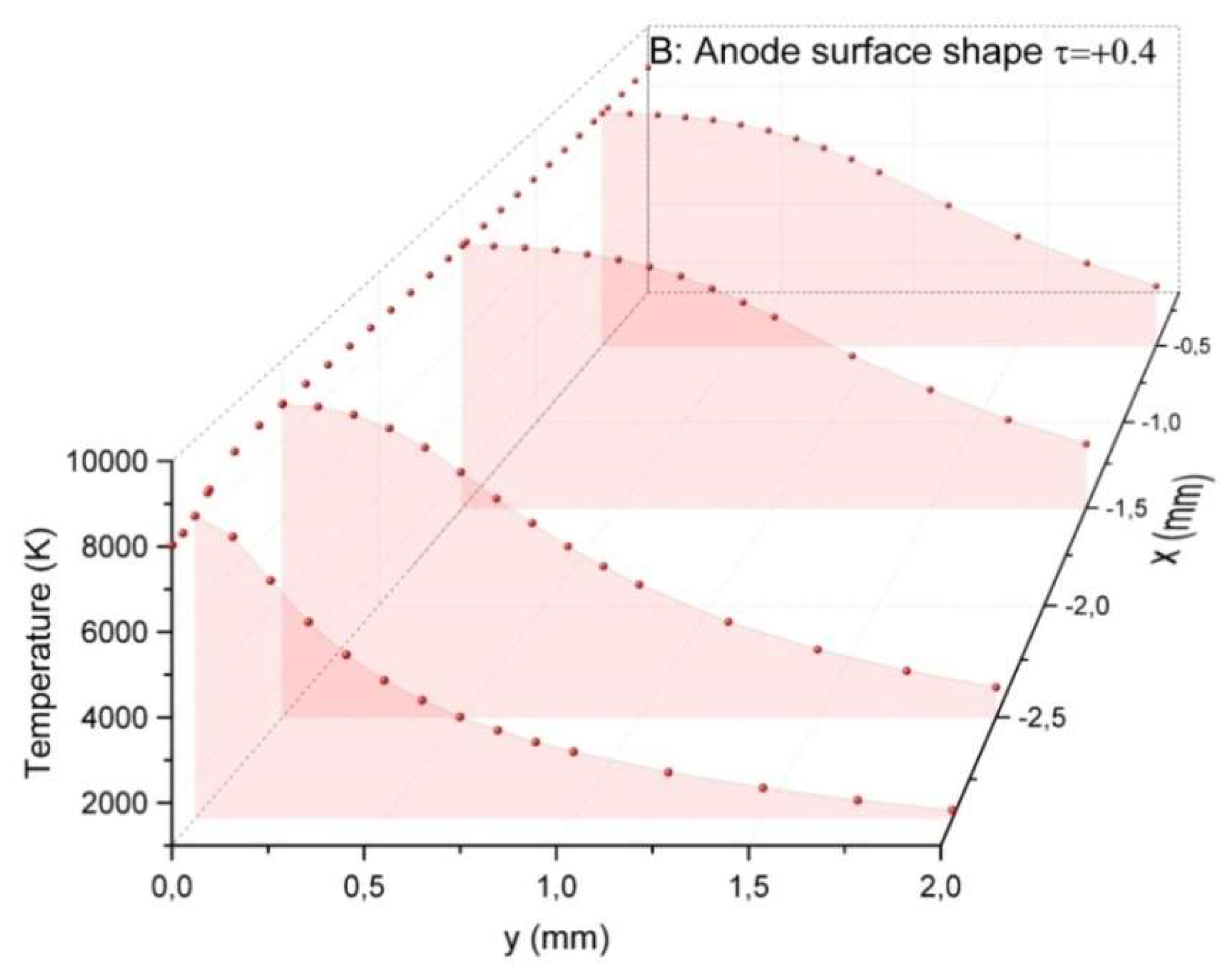
The temperature radial dependence for the concave shape of the anode (
Figure 6A) is noticeably wider than that for the convex shape (
Figure 6B). It is true for both near-cathode region and anode one, where the difference is more pronounced. It is true for both near-cathode region and anode one, where the difference is more appreciable. The consequence of this temperature behavior should inevitably be an expansion of the radial distribution of the electron density and, hence, an expansion of the electric current channel.
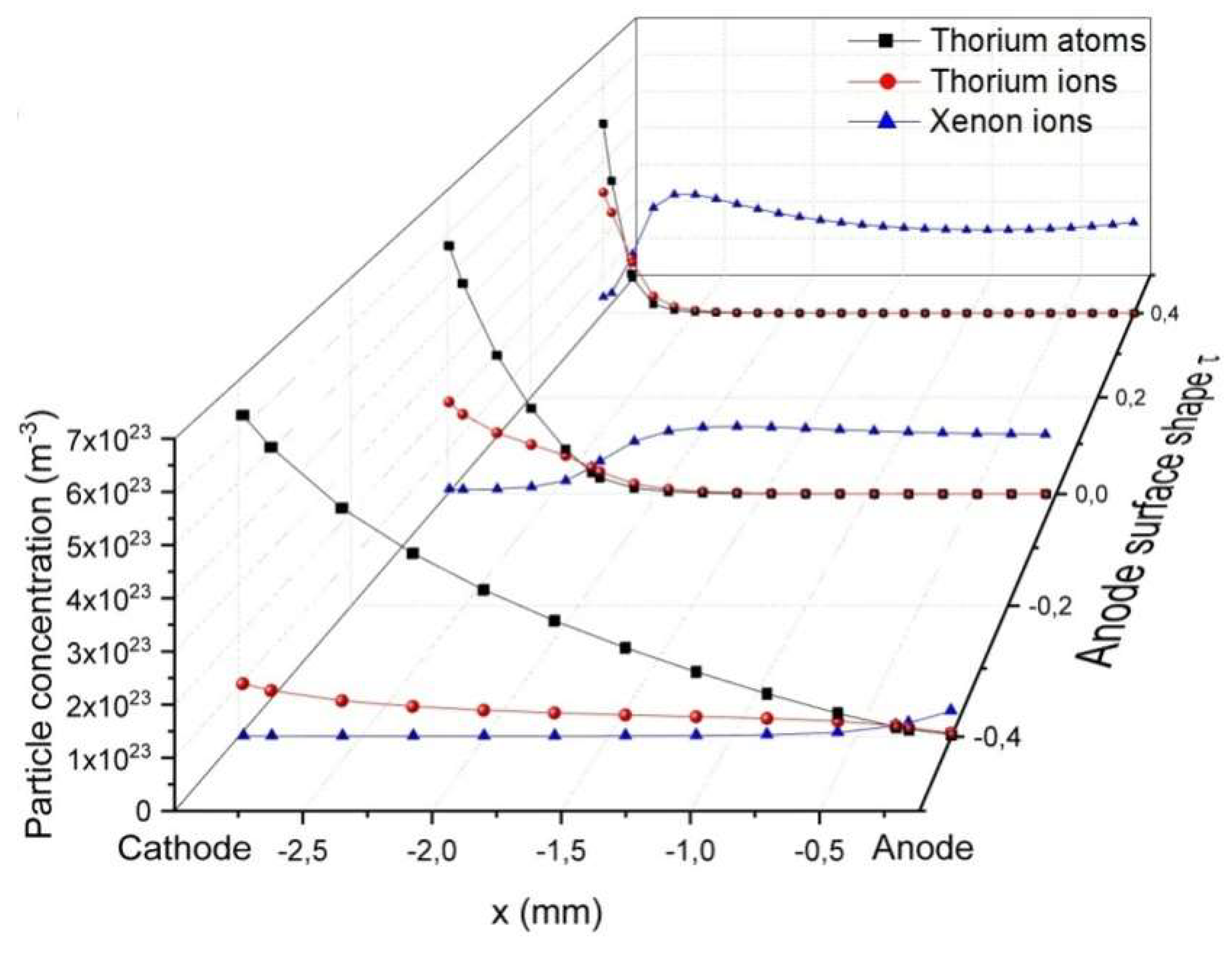
The shape of the anode surface strongly affects the spatial distributions of plasma particles. The following
Figure 7 shows the longitudinal distributions of axial thorium atom concentration N
Th, densities of thorium
and xenon
ions for three shapes of the anode surface: τ
L = −0.4, 0, +0.4.
The case of the flat anode τ
L = 0 (
Figure 7A) was described in [
26] and in [
25] for a discharge between infinite parallel planes. The results demonstrated a strong influence of thorium atom evaporation into the discharge volume. The main conclusion was the predominance of thorium ions and, as a result, the low plasma temperature in the near-cathode region. Another important result was that the density of xenon ions tended to be close to zero in this region.
Transition to the concave shape of the anode τ
L = −0.4 dramatically changes the plasma particle distribution (
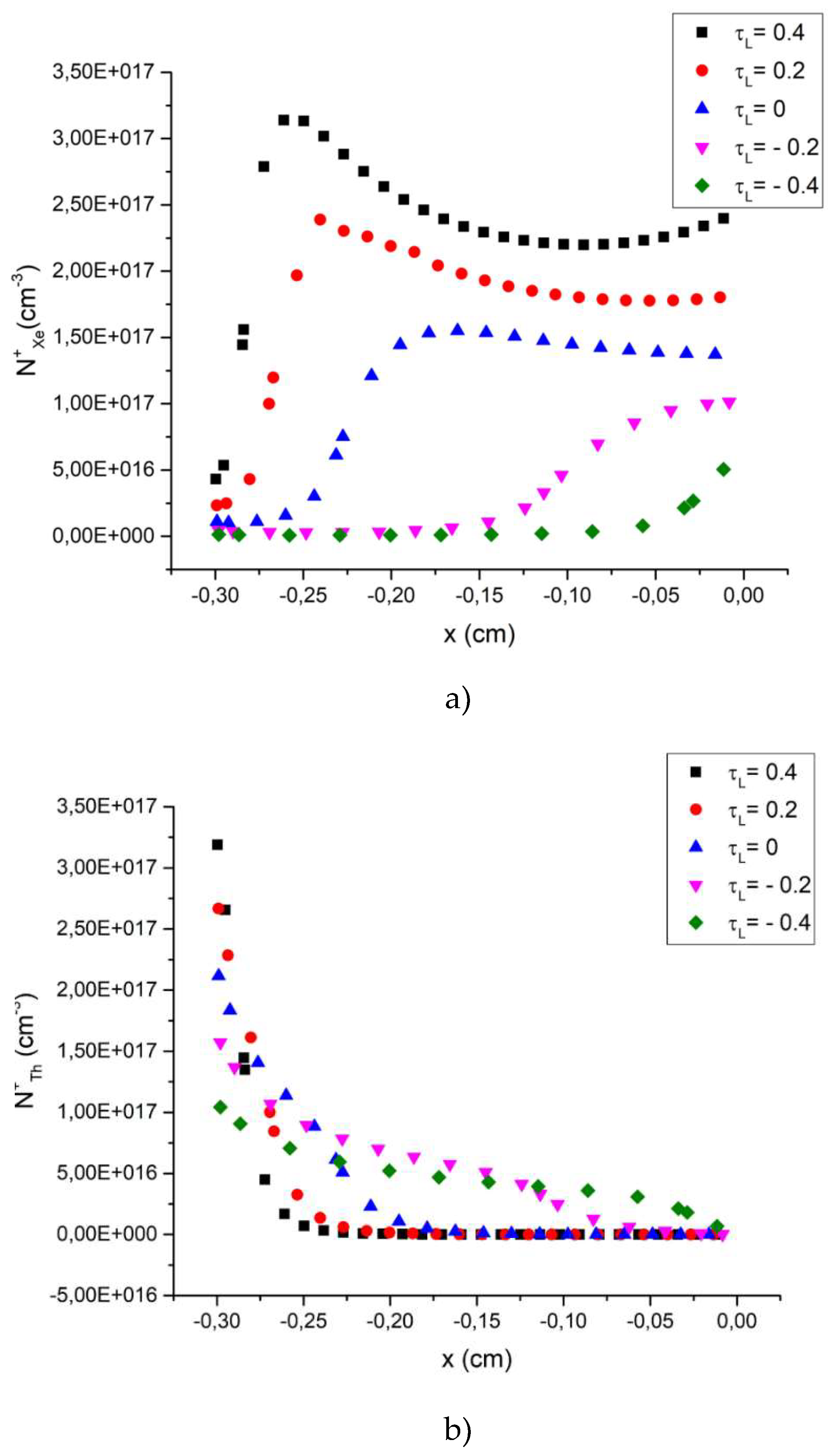
Figure 7B). Thorium atoms are actually located in the entire discharge gap, the xenon ion density is close to zero almost to the anode, so that the main type of ions in the gap is thorium one.
The distribution of plasma particles changes no less sharply upon the transition to the convex shape of the anode surface τ
L = +0.4 (
Figure 7C). The presence of thorium particles is still noticeable near the cathode, but the length of this region is rather small. It can be seen that really the main ions in the entire volume of the plasma are xenon ones. The ion density is approximately 3-5 times higher than for the concave anode shape. This is clear if we take into account the high plasma temperature for the convex anode configuration (see
Figure 5).
A very important issue concerning any discharge plasma is the possibility of practical use of this discharge. For a high current high-pressure xenon discharge this is primarily a light source. We see that the shape of the anode surface strongly affects 1) the plasma temperature and 2) the spatial distributions of plasma particles, above all thorium and xenon ions. The concave anode shape provides the lower plasma temperature and high thorium ion density (at least in the near-cathode region); the convex anode shape gives opposite result: the significantly higher plasma temperature and predominance of xenon ions in the discharge gap. It is known (see e.g., [
28]) that the optical radiation of such a discharge is mainly generated by the processes of bremsstrahlung and recombination of plasma ions. Therefore, there is an opportunity of influencing the plasma temperature, the particle composition and, consequently, the optical radiation of the plasma in question by choosing appropriate shape of the electrode surface, first, the anode surface. The plasma temperature is defining factor in the ionization and excitation in plasmas (the higher the temperature, the higher the concentration of excited atoms and the density of ions). The thorium evaporation into the discharge volume changes both factors, plasma temperature and content of ions, and, therefore, changes the generation of optical radiation including the emission of atomic spectrum lines.
In support of the above, the following
Figure 8 shows in more detail the change in the concentration of xenon and thorium ions for various anode shapes. The convex anode surface really ensures the predominance of xenon ions in the entire discharge gap; at the concave case xenon ions are located only near the anode. On the contrary, thorium ions are located near the cathode in the convex case and spread towards the anode when the surface of the anode is concave. This should give a change in the light generation.
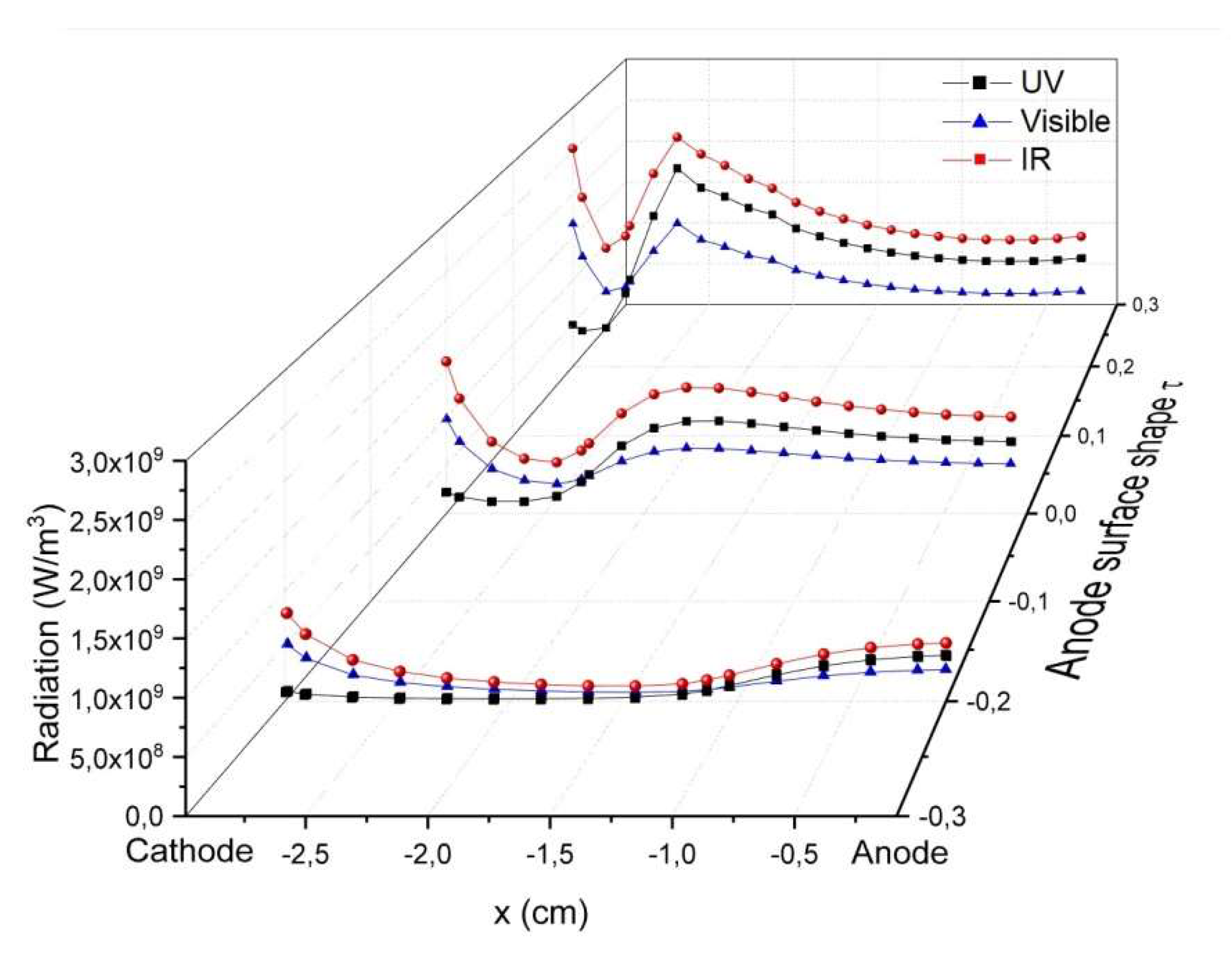
Figure 9 presents the radiation in three spectral regions: ultraviolet (UV) region Δλ = (200−400)nm, visible region Δλ = (400−800)nm, and infrared (IR) region λ > 800nm for three anode surface shapes: τ
L = −0.2, 0, +0.2. The radiation is obtained by integrating the spectral density on the discharge axis in the specified ranges of the spectrum [
28].
The shape of the anode surface actually strongly affects the optical radiation of the plasma. The convex case of the anode surface provides the higher radiation intensity and its maximum is closer to the cathode. The drop in the plasma temperature with the concavity of the anode surface gives the lower radiation intensity and shifts its maximum towards the anode. The UV radiation in the near-cathode region is close to zero for all three anode configuration, because of the low plasma temperature. Ultraviolet radiation is largely formed due to the processes with xenon ions; therefore, this radiation is very sensitive to the plasma temperature. The visible radiation is not so sensitive to T, and its intensity is quite high near the cathode. Moreover, for the concave anode shapes the visible intensity is significantly higher than the UV radiation.
Figure 9 shows that the IR emission prevails over the other two – UV and visible radiations. This is due to the fact that it includes two parts – xenon spectrum lines in the range of ~(870−1070)nm and recombination-bremsstrahlung continuum at λ > 800nm. The latter is more intense for the discharge conditions in question and infrared region λ > 800nm where bremsstrahlung prevails over the recombination processes [
28]. The following
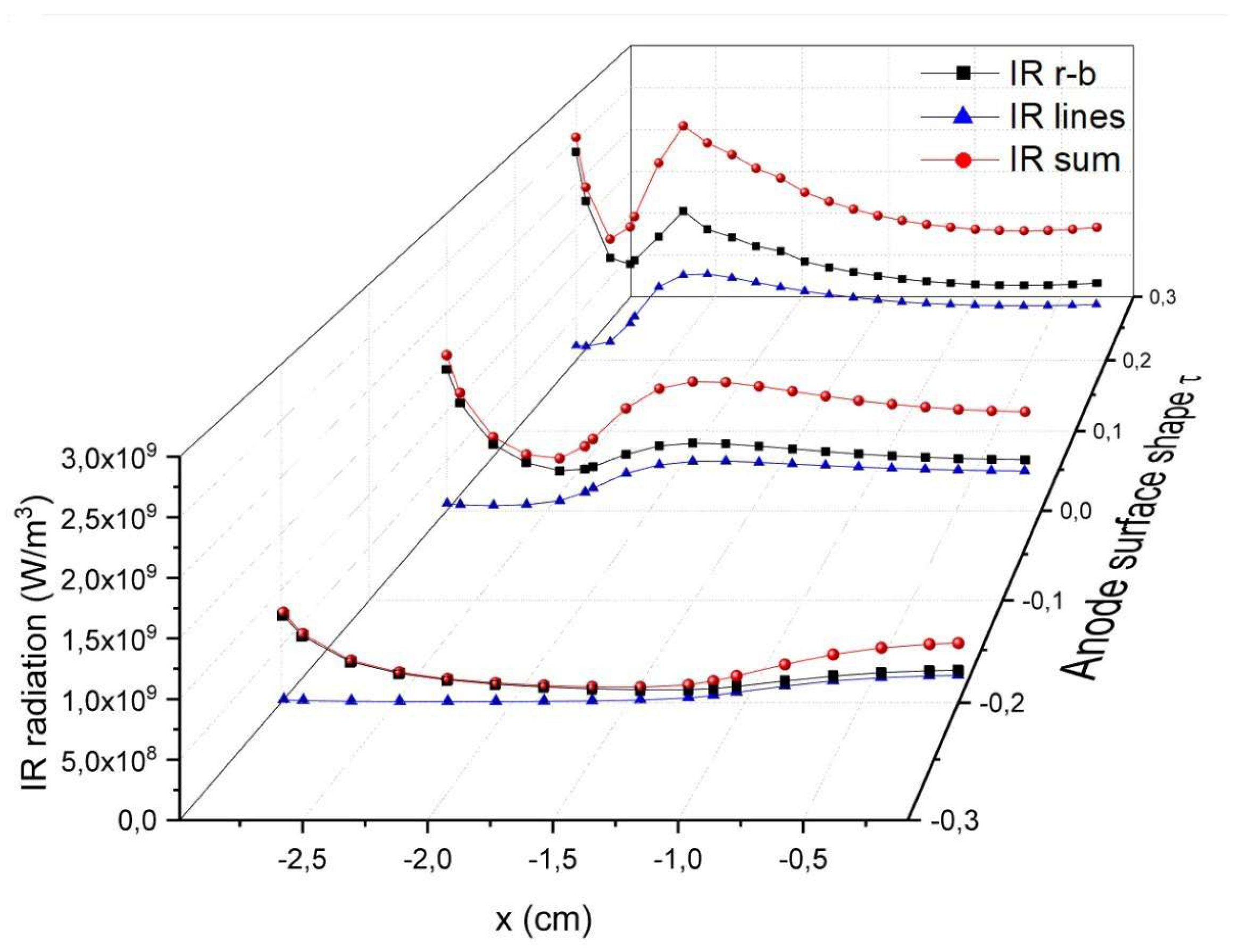
Figure 10 presents the longitudinal distribution of IR radiation at various anode shapes: recombination-bremsstrahlung radiation (IR r-b), spectrum lines (IR lines) and total intensity (IR sum). One can see that the intensity of xenon spectrum lines is about two times less than in the continuum and is close to zero near the cathode due to its strong dependence on the plasma temperature. Note here that the intensity “IR r-b” is quite high mainly due to the integration of the spectral density to infinity.
The intensity of the plasma radiation on the discharge axis decreases when using the concave anode shape (see
Figure 9). This is due to the lower plasma temperature and the change in the composition of plasma particles. However, the total radiation from the discharge as a whole should be comparable for all considered cases: the electric power supplied to the plasma is approximately equal for all cases (the electric current is the same, and the discharge voltage is approximately the same as well, see
Figure 4), the radiation is the main power output in the energy balance, and the concave anode shapes provide wider radial distributions of plasma characteristics, which increases the area of optical light generation.
This raises a very important question regarding the efficiency of light generation in the desirable spectral region.
Figure 9 shows that the convex anode configuration is preferable for optical emission in UV and IR spectral regions, the concave anode configuration is preferable for light (visible) generation. Therefore, by choosing the shape of the anode surface it is possible to optimize the emission spectrum and more efficient use of the electricity supplied to the light source.
4. Conclusions and further prospects
The main result of the previous researches was the development of a short-arc xenon discharge model for real geometry taking into account evaporation of thorium atoms from a thoriated tungsten cathode into a discharge volume [
26]. The strong influence of thorium atoms on plasma properties was shown. Addition of thorium to the plasma decreased the plasma temperature, increased the strength of the electric field, and changed the composition of ions in the discharge gap. The data obtained were in reasonable agreement with the known ones [
1] and the results for the one-dimensional model [
25].
The question that seems very interesting and has not yet been investigated is to study the effect of the shape of the electrode surface on the plasma properties. One can argue that this influence should be noticeable. The role of the cathode surface shape is quite expected: the smaller the cone angle, the higher the temperature due to the higher strength of the electric field near the cathode surface. The role of the anode surface shape is much more complex and somewhat unexpected. As it was shown there is a significant difference between the discharges with a concave and a convex anode surface: the concave anode provides lower values of the strength of the electric field, lower plasma temperature, and wider radial distributions of plasma characteristics. The convex shape provides higher values of the electric field strength, higher plasma temperature, and narrower radial distributions of plasma characteristics.
The shape of the anode surface affects the composition and spatial distributions of plasma particles, in particular, xenon and thorium ions. This leads to the consequence change in the plasma optical emission. The convex shape of the anode increases the UV recombination radiation and IR xenon spectral lines emission (due to the higher plasma temperature), while the concave shape reduces these emissions and increases the radiation in the visible region. We believe that the results obtained can give the impact of cathode and anode designs for the development of xenon light sources with desirable characteristics.
Several important questions arise here.
Changing the shape of the electrode surface can undoubtedly affect the lamp lifetime and lumen maintenance. The cathode cone angle is very important because of the influence on the temperature of the cathode tip – the sharper the angle, the higher the temperature and the shorter the lamp life. Apparently, the cone angle of modern xenon lamps with thoriated cathodes is optimized and can hardly be changed. As shown, changing the shape of the anode surface seriously affects the characteristics of the plasma. We suppose that the lamp life does not decrease due to an increase in the anode working surface for at least the concave shapes, because the anode with the concave shape reduces the electric field strength, plasma temperature, expands the electric current channel, and, hence, decreases the power load on the anode surface. However, it remains to be seen whether the radiation spectrum is preserved, what is the efficiency of optical radiation generation, and what is the lamp life when changing anode surface shape. These questions are supposed to be studied in the future.
There is another issue that should undoubtedly attract our attention. It is known [
32] that for a low pressure discharge the transition from DC to pulse-periodic power supply strongly affects the discharge characteristics, and under certain conditions makes it possible to increase the power share going to the excitation of atoms and molecules. In the case of a discharge in the mixture of mercury vapor with rare gases the pulse-periodic power supply allows one to increase the efficacy of mercury fluorescent lamps [
32].
The transition to a pulse-periodic mode in the case of a short-arc high-pressure xenon discharge can also give new opportunities to improve xenon lamp characteristics. Firstly, one can expect that the electric field strength in current pulses of a pulse-periodic discharge is higher than in a DC discharge; so the plasma temperature is also higher. The irradiance of the discharge plasma under the local thermodynamic equilibrium (LTE) does not correspond to the emission of an absolutely black (gray) body, for which the total (integrated) radiation is proportional to the plasma temperature in the fourth power. Nevertheless, one can assume that for a high-pressure xenon discharge the total radiation is also a strong rising function of the plasma temperature. If the growth of the electric power supplied to the discharge is lower than the increase in the radiation power, one should expect an increase in the light emission output. Secondly, the pulse-periodic supply can reduce the thermal load onto the electrodes, since the time averaged current is expected to be less. Thirdly, an additional gain could be achieved due to the change in the regime of the diffusion and drift movement of the thorium atoms and ions in the plasma in question. Indeed, in a DC mode the thorium atoms evaporate into the plasma from the cathode surface, are ionized and return to the cathode as positive ions. Therefore, the “thorium cloud” near the cathode is formed by the diffusion motion of the thorium atoms from the cathode and the reverse drift of the positive thorium ions to the cathode in the attracting electric field. In the afterglow of a pulse-periodic discharge the electric field strength is close to zero, so that the thorium ions move in the diffusion regime (the time that it takes for the attracting electric field to get the thorium ions back to the cathode is less). Even if the thorium ions recombine in the afterglow, the resulting thorium atoms remain in the plasma, increasing the “thorium cloud”. This can lead to an increase in the size of the cathode spot and, as a consequence, in the total optical emission of atoms and thorium ions.
These assumptions have been confirmed experimentally [
24]. For the pulse-periodic discharge, two effects were described: a decrease in the anode temperature of about 400K and an increase in the light efficiency of about 35% in some discharge conditions. These can be used for the development of more powerful and effective xenon light sources. Changing the shape of the anode surface may provide new opportunities for such development. This issue will be studied in the future.
The results of the study are valid for discharges with another doping of a cathode (e.g., currently investigated compounds with rare earth elements La
20
3-W, ZrO
2-W, CeO
2-W, Y
20
3-W [
33], Ce-W, La-W, Y-W [
34]). Moreover, we believe that the characteristics of a discharge with an undoped cathode are also affected by the shape of the electrode surface, but may be to a lesser extent.
6. Patents
Based on the submitted data, a Patent RU2806877, Short-arc gas discharge lamp of high and ultrahigh pressure, 26.11.2021, was obtained.
Author Contributions
Conceptualization, Timofeev N.A.; Zissiz G.; formal analysis, Sukhomlinov V.S.; methodology, Timofeev N.A.; Sukhomlinov V.S.; Zissis; project administration, Timofeev N.A.; software, Mukharaeva I.Yu.; Borodina V.S.; supervision, Timofeev N.A.; Mustafaev A.S-U.; validation, Solikhov D.Q.; Makhsudov B.I.; writing - original draft, Timofeev N.A.; Zissis G.
Funding
This research was funded by the Theoretical Physics and Mathematics Advancement Foundation “BASIS”, the grant No 22-1-1-61-1 and the Russian Science Foundation (RSF), the grant No 21-19-00139.
Data Availability Statement
All necessary information about modeling and used constants (reaction rates, cross-sections etc.) can be found in our previously published papers (see References to the manuscript).
Conflicts of Interest
The authors declare no conflicts of interest.
References
- Rokhlin, G.N. Discharge light sources, 2nd ed.; Energoatomizdat”: Moscow, Russia, 1991; pp. 674–697. [Google Scholar]
- Benilov, M. Plasma-physics aspects of high-intensity discharge lamps. Summer school on Plasma Physics PlasmaSurf 2016, Portugal, Oeiras, Jul. 15, 2016. http://plasmasurf.tecnico.ulisboa.pt.
- Neiger, M.; Hoppstock, R.; Kleiner, B. A Xenon short arc discharge lamp. US Patent 4 937 496, Jun. 26, 1990.
- Bergner, A.; Scharf, F.H.; Kuhn, G.; Ruhrmann, C.; Hoebing, T.; Awakowicz, P.; Mentel, J. Simulations of the hot core mode of arc attachment at a thoriated tungsten cathode by an emitter spot model. Plasma Sources Sci. Technol. 2014, 23, 054005–054017. [Google Scholar] [CrossRef]
- Chittka, U.; Postma, P.; Schlager, W. Electrodes for gas discharge lamps. App. Surf. Sci. I 1997, 11, pp. 302-310. [CrossRef]
- Bouwknegt, A.; Nienhuis, H.; Schipper, D.J.; Tielemans, P.A.W. Electrodes in discharge lamps. Philips technical Review 1975, 35, pp. 356-359.
- Sillero, J.L.; Ortega, D.; Munoz-Serrano, E.; Casado, E. An experimental study of thoriated tungsten cathodes operating at different current intensities in an atmospheric plasma torch. J. Phys. D: Appl. Phys. 2010, 43, p. 185204. [CrossRef]
- Reinelt, J.; Westermeier, M.; Ruhrmann, C.; Bergner, A.; Awakowicz, P.; Mentel, J. Investigating the dependence of the temperature of high-intensity discharge (HID) lamp electrodes on the operating frequency by pyrometric measurements. J. Phys. D: Appl. Phys. 2011, 44, p. 95204. [CrossRef]
- Zhu, P.; Lowke, J.J.; Morrow, R. A unified theory of free burning arcs, cathode sheaths and cathodes. J. Phys. D: Appl. Phys. 1992, 25, pp. 1221-1230. [CrossRef]
- Wendehtorr, J.; Wohlfahrt, H; Simon, G. Two-temperature, two-dimensional modeling of cathode hot spot formation including sheath effects: In Proceedings of ICOPS’99 [IEEE], 2002. [CrossRef]
- Baeva, M.; Uhrlandt, D.; Benilov, M.S.; Cunha, M.D. Comparing two non-equilibrium approaches to modeling of a free-burning arc. Plasma Sources Sci. Technol. 2013, 22, pp. 065017-065025. [CrossRef]
- Baeva, M. Non-equilibrium modeling of tungsten-inert gas arcs. Plasma Chem. Plasma Process. 2017, 37, pp. 341-370. [CrossRef]
- Minayeva, O.B.; Doughty, D.A. Influence of the Cathode Composition on the Performance of High Pressure Short Arc Xenon Lamps: In Proceedings of 59th GEC Conference, 2006, Columbus, OH.
- Stull, D. In American Institute of Physics Handbook, 3rd ed.; D. E. Gray, Ed.; McGraw Hill: New York, 1972. ISBN 07-001485-X.
- Waymouth, J.F. LTE and Near-LTE Lighting Plasmas. IEEE Trans. Plasma Sci. 1991, 19, p. 1003. [CrossRef]
- Hoebing, T. The anodic emitter effect and its inversion demonstrated by temperature measurements at doped and undoped tungsten electrodes. J. Phys. D: Appl. Phys. 2016, 49, p. 155504. [CrossRef]
- Polk, J.; Mikellides, I.; Katz, I.; Capece, A. Tungsten and barium transport in the internal plasma of hollow cathodes. J. App. Phys. 2009, 105, p. 113301. [CrossRef]
- Polk, J.; Mikellides, I.; Capece, A.; Katz, I. The effect of cathode geometry on barium transport in hollow cathode plasmas. J. Appl. Phys. 2014, 115, p. 183301. [CrossRef]
- Patent DE102010024240 A1, IPC: H01J-009/02 H01J-061/00 H01J-061/04 H01J-061/073 H01J-061/84 H01L-021/027, 2009-06-30.
- Patent DE102010044259 B4, IPC: H01J-061/06 H01J-061/073 H01J-061/84 H01J-061/86 H01J-061/88, 2009-09-15.
- Patent JP2011065756 A, Short arc discharge lamp, H01J-061/073*, 2009-09-15.
- Patent JP4337968 B2, Short arc type discharge lamp, H01J-061/073* H01J-061/86 H01J-061/88.
- Flesch, P.; Neiger, M. Time-dependent simulation of plasma and electrodes in high-intensity discharge lamps with different electrode shapes. J. Phys. D: Appl. Phys. 2003, 36, pp. 849–860. [CrossRef]
- Timofeev, N.A.; Sukhomlinov, V.S.; Zissis, G.; Mukharaeva, I.Yu.; Dupuis, P. Investigation of short-arc high-pressure xenon discharge: effect of electrode material evaporation on discharge properties and pulse operation. IEEE Trans. Plasma Sci. 2019, 47, pp. 3266-3271. [CrossRef]
- Timofeev, N.A.; Sukhomlinov, V.S.; Zissis, G.; Mukharaeva, I.Yu.; Dupuis, P. Simulation of an Ultra-High Pressure Short-Arc Xenon Discharge Plasma. Technical Physics 2019, 64, pp. 1473-1479. [CrossRef]
- Timofeev, N.A.; Sukhomlinov, V.S.; Zissis, G.; Mukharaeva, I.Yu.; Mikhaylov, D.V.; Mustafaev, A.S.; Dupuis, P.; Solikhov, D.Q.; Borodina, V.S. Modeling of high pressure short-arc xenon discharge with a thoriated cathode. IEEE Trans. Plasma Sci. 2021, 49, pp. 2387-96. [CrossRef]
- Korn, G.A.; Korn, T.M. Mathematical Handbook for Scientists and Engineers: Definitions, Theorems, and Formulas for Reference and Review. Courier Corporation: 2013, 1152p. ISBN 0486320235, 9780486320236.
- Raizer, Yu.P. Gas Discharge Physics. 3rd ed.; Publ. House “Intellect”: Moscow, 2009; 734 p. ISBN: 978-5-91559-019-8.
- Granovsky, V.L. Electric current in gases. Steady state current. Nauka Publ.: Moscow, 1971; 543 p.
- Aymar, M.; Coulombe, M. Theoretical transition probabilities and lifetimes in Kr I and Xe I spectra. In Atomic Data and Nuclear Data Tables 1978; 21, no. 6, 537-566. Online ISSN: 1090-2090 Print ISSN: 0092-640X. [CrossRef]
-
https://physics.nist.gov/asd National Institute of Standards and Technology (NIST). [CrossRef]
- Milenin, V.M.; Timofeev, N.A. Plasma of low-pressure gas discharge light sources; Leningrad University Publ.: St-Petersburg, Russia, 1991; pp. 144-180.
- Haidar, J.; Farmer, A.J.D. Surface temperature measurements for tungsten-based cathodes of high-current free-burning arcs. J. Phys. D: Appl. Phys. 1995, 28, pp. 2089-2094. [CrossRef]
- Gu, Z.; Xi, X.; Yang, J.; Xu, J. Properties of RE-W cathode and its application in electrostatic precipitation for high temperature gas clean-up. Fuel 2012, 95, pp. 648-654. [CrossRef]
Figure 1.
The geometry of the discharge in question in the ellipsoidal coordinate system: thick blue lines on the left with the coordinates τ = −0.924, −0.850 are the cathode surfaces; thick red lines with the coordinates τ = −0.4, −0.2, 0, +0.2, +0.4, +0.924 are the anode surfaces; a thick dashed line is the outer border of the electric current channel. The Cartesian coordinate grid is also shown in the figure.
Figure 2.
The electric field strength E on the discharge axis for the different shape of the anode τL = −0.4, −0.2, 0, +0.2, +0.4; the cathode shape is τ0 = −0.924. The electric current i is 10A; the thorium concentration on the cathode surface is 7 · 1023m−3; the xenon atom concentration NXe is 3 · 1025m−3. The absolute values of E near the cathode are indeed higher in the discharge with the convex shape of the anode. The electric field strength E is given in the Cartesian coordinates (x is the longitudinal coordinate along the discharge axis).
Figure 3.
The radial dependence of the electric field strength E(y) (y is the Cartesian coordinate) for two anode surface shapes τL = −0.4 (concave) and τL = +0.4 (convex) at different points on the discharge axis x = −2.9mm, −2.5mm, −1.5mm, −0.5mm Discharge conditions are as follows: i = 10A, It is seen that the concave surface (A) is characterized by a broader distribution of the electric field in the discharge volume compared to the convex shape (B).
Figure 4.
The discharge voltage U for the various anodes with τL = −0.4, −0.2, 0, +0.2, +0.4 in dependence on the concentration of thorium atoms . i = 10A NXe = 3 · 1025m−3. One can see an increase in the voltage with an increase in the thorium concentration, so that at = 7 · 1017m−3 it is close to ≈3.1 – 3.2V and does not strongly depend on the anode shape.
Figure 5.
The plasma temperature T for the shape of the cathode τ0 = −0.924 and the shapes of the anode τL = −0.4, −0.2, 0, +0.2, +0.4. The discharge parameters are as follows: i = 10A; = 7 · 1023m−3; NXe= 3 · 1025m−3. The convex surface shape of the anode significantly increases the plasma temperature.
Figure 6.
The radial distribution of the plasma temperature T(y) for two shapes of the anode τL = −0.4, +0.4. The discharge parameters are as follows: i = 10A; = 7 · 1023m−3; NXe= 3 · 1025m−3. The distributions are broader for the concave anode. The difference is more noticeable in the area near the anode (x = −0.5mm).
Figure 7.
The plasma particle distributions for the various shapes of the discharge anode: flat anode τL = 0 (A), concave anode τL = −0.4 (B), and convex anode τL = +0.4 (C). The discharge parameters are as follows: i = 10A; = 7 · 1023m−3; NXe= 3 · 1025m−3. The transition from the concave shape of the anode to the convex one radically changes the content of particles in the plasma. In the concave case thorium atoms actually extend all the way to the anode, in the convex case the picture is the opposite: xenon ions are the main ones in the discharge gap. The flat anode case (τL = 0) occupies an intermediate position. The discharge gap is the same (3 mm) for the three shapes presented.
Figure 8.
The longitudinal distribution of xenon (a) and thorium (b) ion densities for various shapes of the anode τL = −0.4, −0.2, 0, +0.2, +0.4. The discharge parameters are as follows: i = 10A; = 7 · 1023m−3; NXe= 3 · 1025m−3.
Figure 8.
The longitudinal distribution of xenon (a) and thorium (b) ion densities for various shapes of the anode τL = −0.4, −0.2, 0, +0.2, +0.4. The discharge parameters are as follows: i = 10A; = 7 · 1023m−3; NXe= 3 · 1025m−3.
Figure 9.
The radiation in three spectral regions: UV Δλ = (200−400)nm, visible Δλ = (400−800)nm, and IR λ > 800nm for three anode surface shapes: τL = −0.2, 0, +0.2. The discharge conditions are as follows: i = 10A; = 7 · 1023m−3; NXe= 3 · 1025m−3.
Figure 9.
The radiation in three spectral regions: UV Δλ = (200−400)nm, visible Δλ = (400−800)nm, and IR λ > 800nm for three anode surface shapes: τL = −0.2, 0, +0.2. The discharge conditions are as follows: i = 10A; = 7 · 1023m−3; NXe= 3 · 1025m−3.
Figure 10.
The intensity of the infrared radiation in dependence on the anode surface shape: recombination-bremsstrahlung radiation (IR r-b), spectral lines (IR lines), and total intensity (IR sum). The discharge conditions coincide with those shown in
Figure 9.
Figure 10.
The intensity of the infrared radiation in dependence on the anode surface shape: recombination-bremsstrahlung radiation (IR r-b), spectral lines (IR lines), and total intensity (IR sum). The discharge conditions coincide with those shown in
Figure 9.
|
Disclaimer/Publisher’s Note: The statements, opinions and data contained in all publications are solely those of the individual author(s) and contributor(s) and not of MDPI and/or the editor(s). MDPI and/or the editor(s) disclaim responsibility for any injury to people or property resulting from any ideas, methods, instructions or products referred to in the content. |
© 2024 by the authors. Licensee MDPI, Basel, Switzerland. This article is an open access article distributed under the terms and conditions of the Creative Commons Attribution (CC BY) license (http://creativecommons.org/licenses/by/4.0/).
