1. Introduction
In the digital age, marked by a drive towards data-driven processes, the megatrends of Industry 4.0 and the Internet of Things (IoT) are increasingly coming into focus and bring with them the need for data acquisition. Specifically, in the manufacturing sector, a fivefold increase in data volumes is forecasted, creating a demand for sensor technologies in complex environments [
1]. In this context, filament-shaped sensors (FSS) are gaining crucial importance due to the small size and flexibility. The filament form is especially fitting to integration into textile-based applications. The monitoring of fibre reinforced composites has been of focus for many years, in which commercial strain gauges are applied to the external surfaces or fibre optical sensors (FOS) are integrated during the production [
2,
3]. Although these are important steps to the long-term structural health monitoring of such lightweight components, strain gauges can only measure at the point of application and FOS are often accompanied by expensive and complex measurement equipment. Additionally, the monitoring of civil structures through the sensor integration in geotextiles has been of interest [
4]. Here, sensors provide early detection for needed maintenance, but also alert locals about possible imminent dangers, such as landslides and sinkholes [
5]. Lastly, filament sensors can be integrated into wearable textiles in order to monitor vital signals, such as breathing, which can provide early indications of respiratory problems in epileptic patients, therefore reducing the chance of sudden unexpected death in epilepsy (SUDEP) [
6]. Seeing as how these applications had a wide range of mechanical properties as well as production processes, there is a demand for a versatile FSSs, which provide quantitative information about the current strain in the component or structure.
In order to cover large strain ranges, an elastomeric material is to be chosen. With a refinement to a thermoplastic elastomeric material, this material can be processed to filaments through the industrialized melt spinning process. Through the doping of this elastomeric material with conductive nanoparticles an electrical conductivity can be achieved, which is utilized for the resistive based sensor principle. In order to fulfill these technical requirements, a nanocomposite material consisting of thermoplastic polyurethane (TPU) and carbon nanotubes (CNTs) is chosen as the conductive, sensing material.
There is no shortage of work reporting the development of nanocomposites of TPU and CNTs. Much of the research has focused on understanding the influence of the nanoparticle concentration on the resulting static resistivities. A percolation threshold has been reported, below which no conductive network is formed in the nanocomposite and above which additional doping of the nanoparticles does not contribute to an improvement of the electrical properties. These works have shown that a CNT concentration of 4 wt.% in TPU is generally sufficient in order to employ the filament as a sensor [
7,
8,
9].
Despite the detailed previous work, the filaments are always produced in a fashion so that the filament surface is the electrically conductive component [
7,
8,
9]. This may be beneficial if the sensor is meant to detect moisture or electrical signals, but detrimental when strain is to be sensed in a possible environment of moisture, such as rain or sweat, or other conductive components, such as carbon fiber. In this work a core conducting, bicomponent filament (schematically shown in
Figure 1) is developed as well as a contacting method for the electrical analysis of such filaments.
2. Materials and Methods
2.1. Materials
2.1.1. Sheath component
In order to protect the conductive core from the environment, an insulating sheath is coextruded around the conductive core. A TPU sheath is selected in order to allow for high strains and elasticity during cyclic loading. This TPU sheath is the commercially available Elastollan® 1185 from BASF Polyurethanes GmbH, Lemförde, Germany. This material will be further referred to as TPU1185.
2.1.2. Core component
A nanocomposite material is a multiphase material in which at least one of the phases measures less than 100 nm in one of the dimensions. In this work, multiwalled carbon nanotubes (CNTs) are compounded together with a thermoplastic polymer in order to achieve a conductive polymer nanocomposite. In order to further ensure the high stretchability and elasticity of the filaments as well as a good adhesion between the core and sheath components, a TPU is chosen as the matrix material for the core conducting nanocomposite.
It is widely known that the properties of the starting compound are a critical factor for the final properties of the final product. The dispersion and agglomeration of the compounded particles can rarely be improved upon after the initial compounding process. For this reason, the compound employed in this work is a commercially available material, for which the compounding process has been optimized and a homogeneous product can be produced. The material in this work is a thermoplastic polyurethane (TPU) base with 4 wt.% CNTs by the name PLASTICYLTM TPU from the company NanoCyl SA, Sambreville, Belgium. This material will be further referred to as TPU0401.
2.2. Processing methods
2.2.1. Filament production
Due to the hydroscopic nature of TPU, the granulate materials are dried previously to extrusion to a residual moisture content of < 200 ppm [
10]. For this purpose, the oven LUXOR A from the company motan holding gmbh, Constance, Germany is used. The materials are dried at 80 °C with hot air for 16 hours. The moisture contents are measured using Karl-Fischer titration using the Coulometric KF Titrator C30 from the company Mettler Toledo, Inc., Columbus, Ohio, USA. The moisture content was reduced from 794,8 (+/- 35,16) to 114,233 (+/- 9,08) and 1115,73 (+/- 49,17) to 126,10 (+/- 18,73) for the TPU 1185 and TPU0401, respectively.
The core and sheath materials are formed to filaments using the bicomponent, monofilament melt spinning process. In melt spinning, thermoplastic polymers are fed from a hopper to an extruder, in which a rotating screw is employed along with multiple heating elements to melt and liquify the polymer. Through the heating elements as well as the resulting shear stresses, heat is incorporated into the polymer. This molten polymer is then fed further to a gear spin pump, in order to ensure a constant volume throughput. After the spin pump, filters in the spinning pack are employed in order to remove foreign material and/or gelled polymer. Finally, the polymer passes through the spinneret with a defined hole diameter and capillary length from which the filament receives its form. For the case of bicomponent spinning, two hoppers, extruders and spin pumps are employed for a second polymer stream. These two polymer streams are then fed together into the spinning pack, consisting of the filters and spinneret, where they remain separated until joining in the capillary of the spinneret. Schematic representations of the melt spinning machine as well as the spinneret have been previously shown in [
11]. The precise spinning parameters are shown in
Table 1.
2.2.2. Filament cutting and contacting
In order to analyze the electrical properties a contact must be made with the core component of the filament. A standard contacting method for metallic wires is to strip the wire of the insulating plastic layer. Such a method is not suitable for the contacting of the bicomponent filament because of the strong interfacial adhesion between the core and sheath components. Alternative to stripping of the insulation layer, the conductive surface can be increased through the employment of silver paint. For this, the bicomponent filament is cleanly cut in the cross-section and the cut surface is dipped in silver paint. To protect the silver layer from mechanical damage, such as bending or flaking, a metal crimp is finally added to the surface of the silver paint. The conductive interfaces are shown in
Figure 2.
Three cutting methods are tested in this work: 1) scalpel at room temperature, 2) scalpel after freezing the filament and 3) laser at room temperature. The laser employed in this work is the R500 Rayjet from the company Trotec Laser GmbH, Marchtrenk, Austria. This laser is generally used for cutting or engraving of various materials, including wood, paper, leather and plastics. The main features of the laser cutting machine from this work are shown in
Table 2.
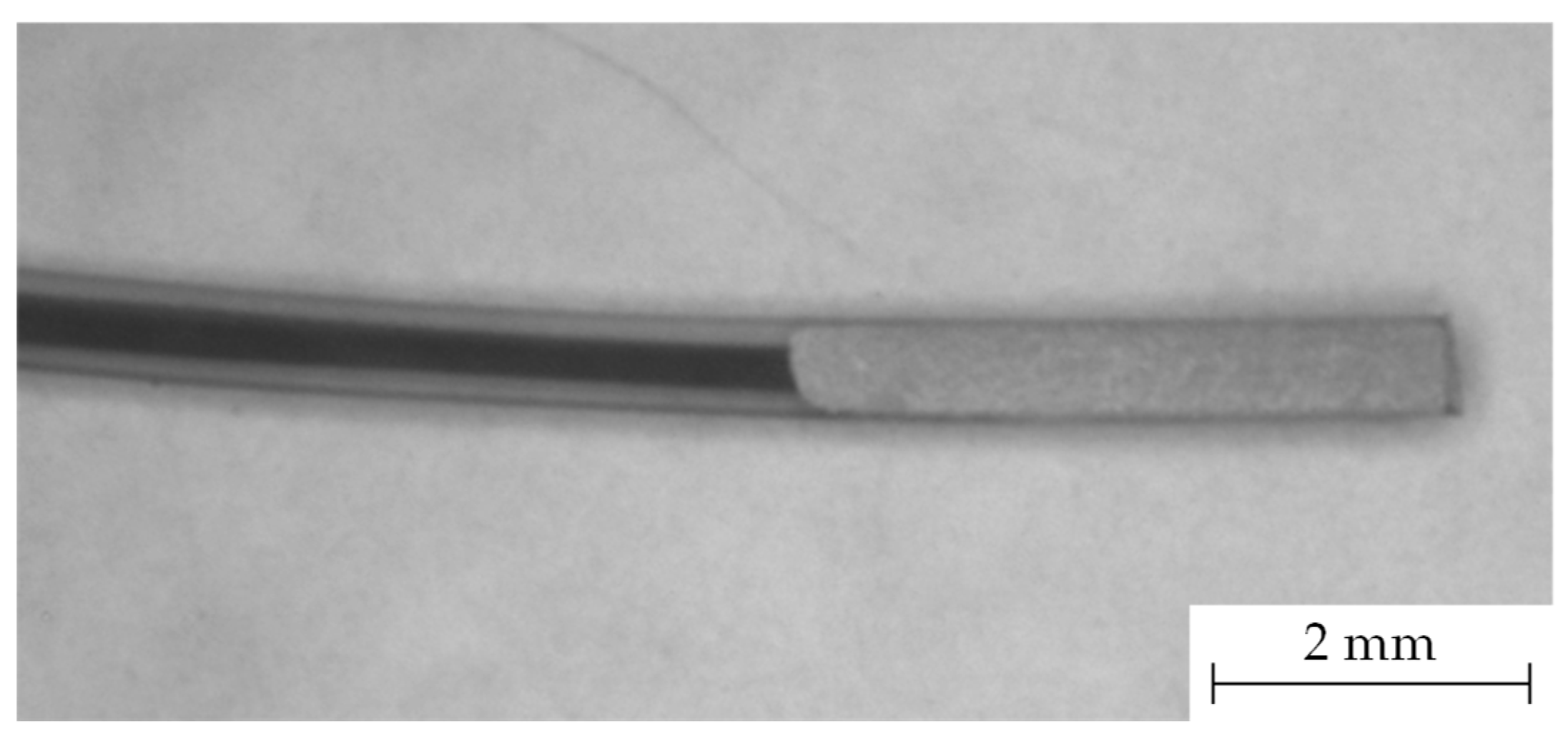
After the core of the filament is exposed through cutting, it is dipped 4 mm in silver paint, covering the cut surface as well as the insulating sheath material. The silver paint used in this work is from the company MARAWE GmbH & Co. KG, Regensburg, Germany. A microscopic image of a cut and silver painted filament can be seen in
Figure 3.
2.3. Analysis methods
2.3.1. Scanning electron microscopy
In order to qualitatively analyze the cut surface, scanning electron microscopy (SEM) is employed. The sample preparation consists of sputtering the as-cut (razor or laser) surface with gold. The SEM used in this work is the FlexSEM 1000 II from the company Hitachi High-Technologies Corporation, Tokyo, Japan.
2.3.2. Static electrical resistivity
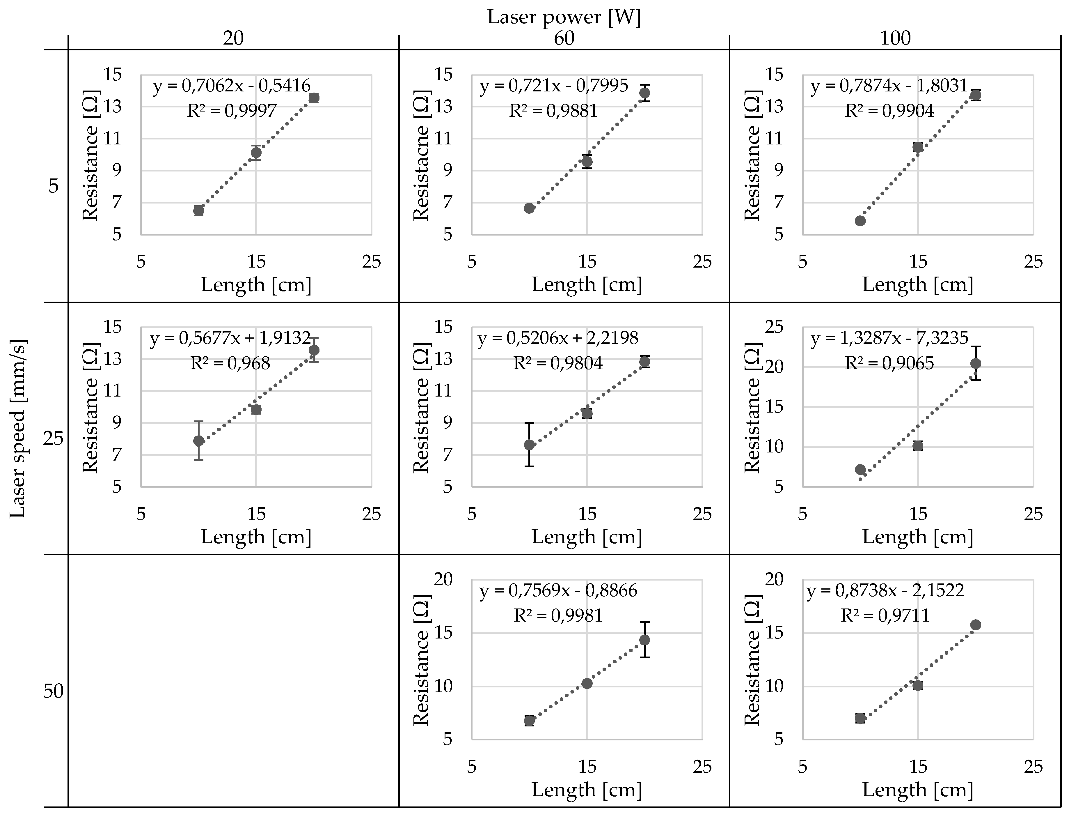
In addition to the qualitative SEM images, the static electrical resistivity of the filaments is measured in order to determine if the varied cutting parameters have a significant influence on the measured resistivity. After the successfully cutting and contacting, the resistance is measured with the multimeter Series 2100: 6 ½ Digit from the company Keithley Instruments, Cleveland, Ohio, USA in DC current. A four-point measurement method is used. In order to evaluate the contact resistances of the multiple interfaces, samples are cut to 3 different lengths (10, 15 and 20 cm) and the resulting resistance is plotted in relation to the cut length. Ideally, the data points form a linear trend and the y-intercept of the extrapolated trendline goes to 0. The linear resistance is calculated using the equation below
where R is the resistance in MΩ, L is the length of the filament in m and R
L is the linear resistivity in MΩ/m.
3. Results
The results of this work are separated into two sections. First the pretrials of the cutting with the razor at room temperature, after freezing and laser cutting will be described. Subsequently, the determination of the optical laser cutting parameters based on qualitative and quantitative analysis will be presented. For all the trials the filament described in
Table 1 is used.
3.1. Cutting pretrials
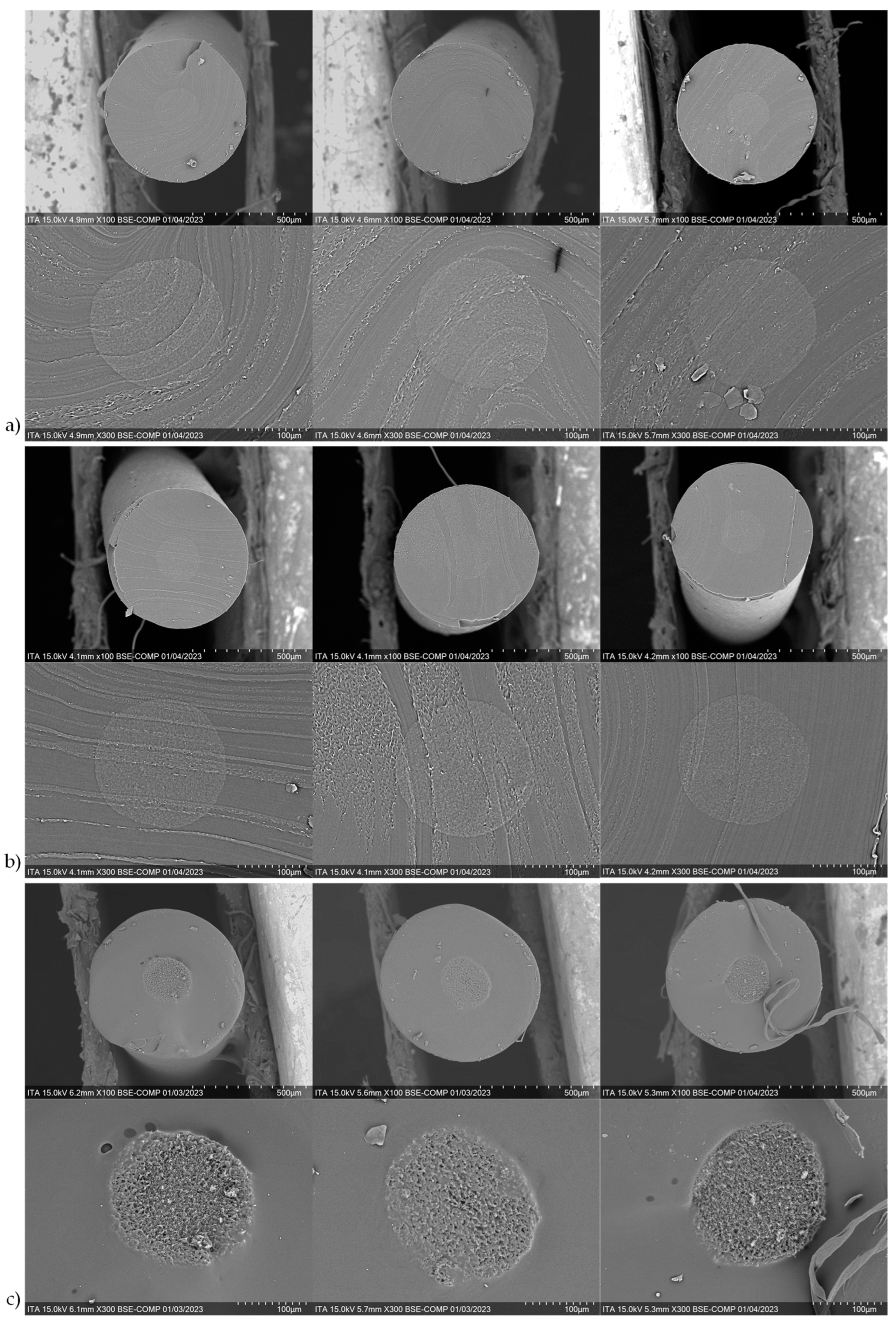
For each of the cutting methods, five samples are imaged with the SEM at two magnification levels (100x and 300x). The core and sheaths of the filaments are visible due to a slight difference in the grey tones of the higher magnified images. For the preliminary trials, the laser power is set to 60 W and the laser speed is set to 25 mm/s. Three representative images per cutting method are shown in
Figure 4.
In addition to the qualitative measurements, the filaments are contacted with silver paint and metal crimps and the electrical resistivities are measured. Unfortunately, the samples cut with the razor, at room temperature and frozen, are unable to be measured because the maximum resistance of the multimeter (100 MΩ) at all lengths is reached and only “Overload” is shown on the display [
13]. The resulting linear resistivity of the laser cut sample could be measured and is 68,21 (+/- 9,87) MΩ/m.
3.2. Determination of the optimal laser parameters
After evaluation of the cutting pretrials, the parameters of the laser cutting machine are investigated in order to determine if they have an influence on the quality of the cut surface and therefore on the electrical contact. For this purpose, the laser speed and laser power were varied. A 2² fully-factorial design of experiments (DOE) was planned, but the combination of the highest speed with the lowest power (50 mm/s and 20 W) was not able to cut through the filament. This is thought to be due to the fact that enough energy cannot be transferred to the filament in the short contact time. The resulting parameters tested are shown in
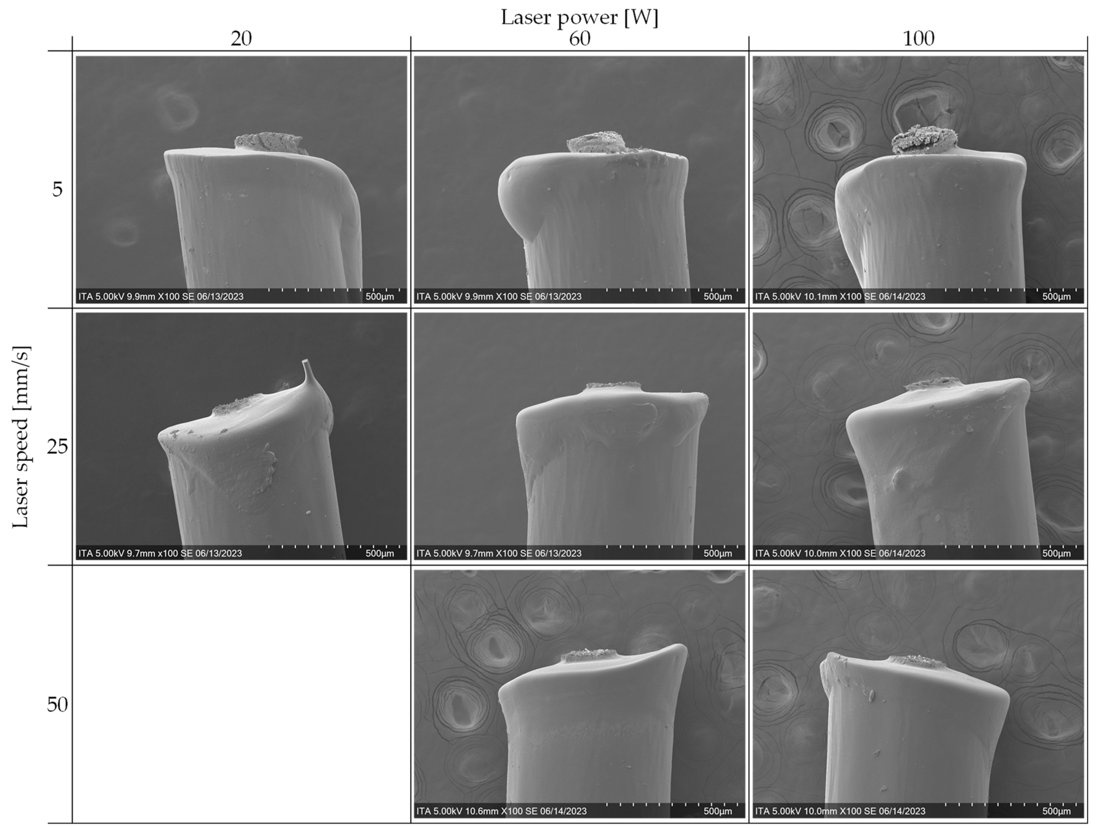
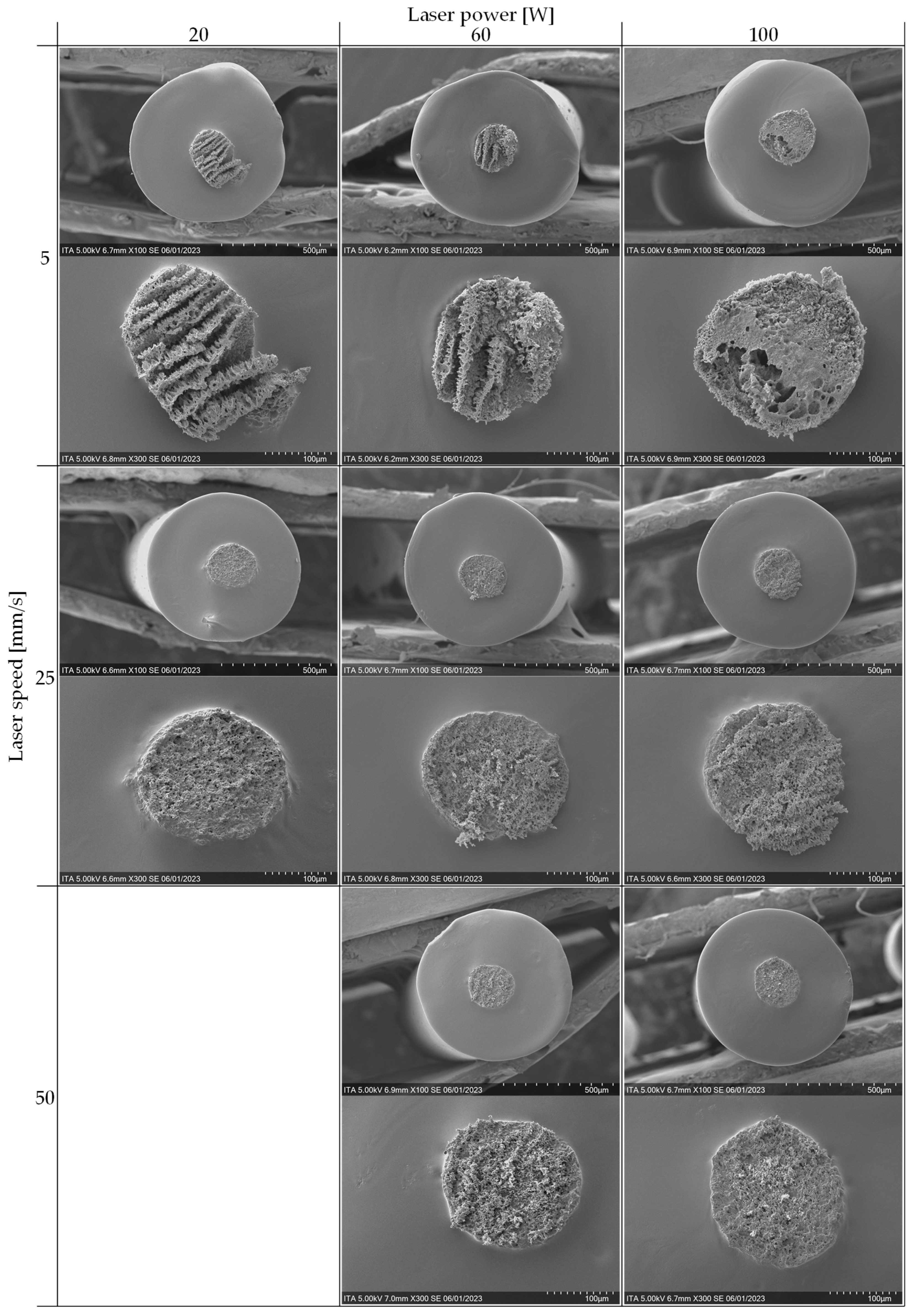
Table 3. As a consequence, two 2² DOEs are analyzed: 1) 5 vs. 25 mm/s and 20 vs. 100 W and 2) 5 vs. 50 mm/s and 60 vs. 100 W. The qualitative results from the SEM images are shown in
Figure 5 and
Figure 6.
The samples are also tested regarding the static linear resistivity. The best cutting parameters are those with the following characteristics:
Low average linear resistivity
Low standard deviation of the linear resistivity
Low absolute value of the y-intercept (length vs. resistance)
Linearity R² close to 1 (length vs. resistance)
The resulting data regarding the linear dependence of resistance is shown in
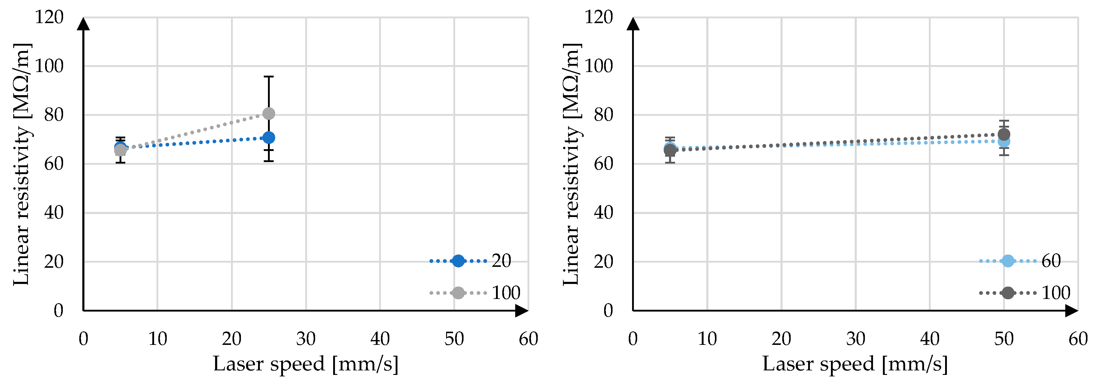
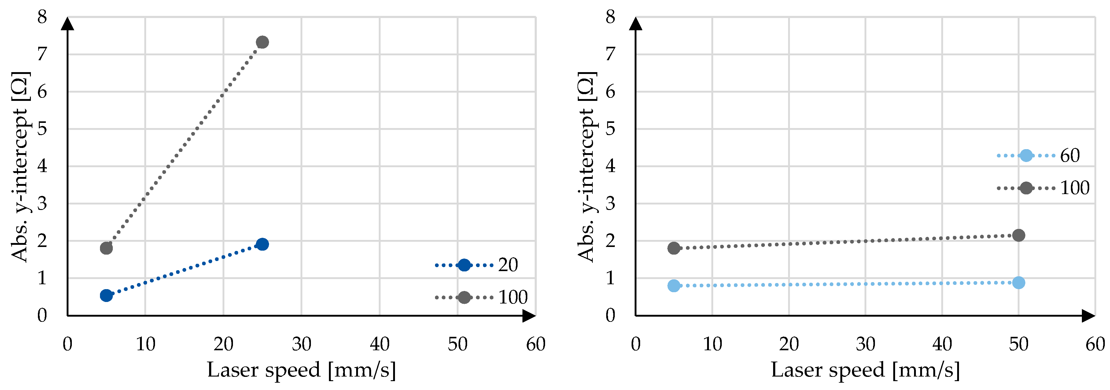
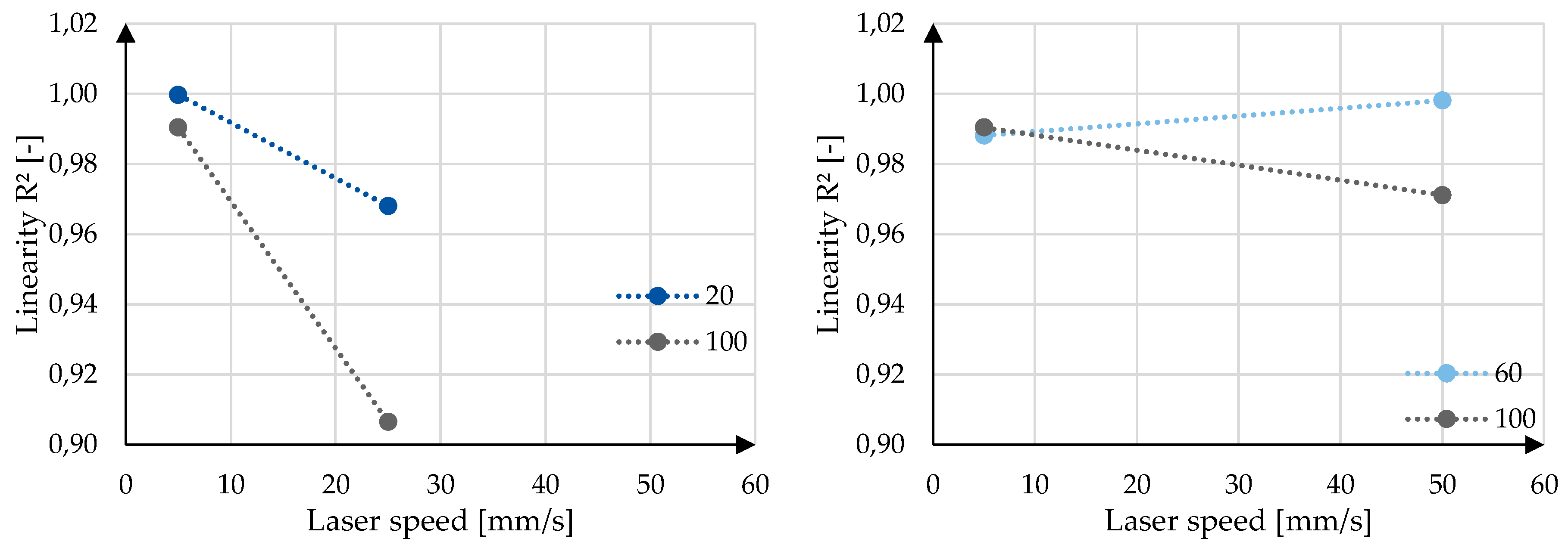
Figure 7. The interaction plots of the laser power and laser speed on the linear resistivity, y-intercept and linearity R² can be seen in
Figure 8,
Figure 9 and
Figure 10 for both comparison groups. Furthermore, the Pareto charts of the standardized effects of the linear resistivity and the laser parameters (A: laser speed, B: laser power) can be seen in
Figure 11. For this statistical analysis a level of confidence of 95 % (α = 0,05) is taken. Depending on the data and the number of samples tested (n = 15), a minimum effect, the reference line, is calculated and above which, the factor is considered significant. For the comparisons 1 and 2 in
Figure 11 these are 10,513 and 5,049 respectively.
4. Discussion
In this chapter, the presented results will be discussed with explanations for phenomena observed. First the SEM images of the pretrials will be evaluated. Subsequently, the SEM images as well as the static linear resistivities of the parameter optimization is discussed.
4.1. Cutting pretrials
In the SEM images, no clear difference can be observed when comparing the razor cut samples cut at room temperature and after freezing. On the other hand, there is a clear difference in the surface properties of the razor and laser cut samples, especially visible in the highly magnified (300x) images. This comparison can be seen in
Figure 12.
It appears that due to the cutting with the razor, the pure TPU from the sheath component is smeared over the conducting core. This would explain the inability to measure the resistance with the multimeter, as the sample, not having a contact to the conductive core, essentially has an infinite resistance. This is a phenomenon, which is not observed while razor cutting filaments with a different sheath material, such as polypropylene (PP) [
11]. This is thought to be due to the different mechanical properties of the sheath materials. TPU is a very soft and elastic material, even at room temperature. Conversely, PP is rather stiff and brittle. This difference makes the cutting and contacting of bicomponent filaments with PP in the sheath relatively trivial, whereas TPU poses a new problem.
Cutting the filaments with the laser essentially burns away the polymer material at the cut surface. This thermal rather than mechanical removal of the material allows for a cleaner cut of the surface. Furthermore, there is a clear difference in the surface of the conducting core and the insulating sheath for the laser cut samples. It is assumed that the CNTs remain to a certain extent in the core and this network structure is then visible as small cavities. This phenomenon is discussed in more detail in the following chapter.
4.2. Determination of the optimal laser parameters
4.2.1. Scanning electron microscopy
When analyzing the cross-sectional SEM images of
Figure 6 some qualitative characteristics can be observed. In only evaluating the three samples cut at 5 mm/s, all have larger and deeper cavities in the core component in comparison to those cut at the higher laser speeds of 25 and 50 mm/s. This is thought to result from the relatively long dwell times of the laser while cutting. Additionally, among the three samples cut at 5 mm/s, a difference can be seen from the lower to the higher laser power. At lower powers, the core has a striped visual effect, whereas the core cut at the higher powers has a more irregular pattern and rather larger, rounder cavities (
Figure 13). It is thought that the regular striped pattern at the lower laser powers results from the pulsing of the laser while moving and cutting the material. These cavities may represent the removal of the CNTs, TPU or both. On the other hand, at higher power (5 mm/s and 100 W), the amount of energy input is so high and the dwell time is so long (due to the slow speed), that the delicate structures remaining at the lower powers are destroyed leaving larger vacancies in the core. This hypothesis would need to be further investigated in following research.
In comparing the samples cut at the higher speeds, the SEM images appear relatively similar; at higher speeds the laser power has less of an influence on the surface. However, the resulting cavities of the samples cut with the two lowest powers (25 mm/s and 20 W; 50 mm/s and 60 W) appear deeper as stronger shadows in the core material. This fine and deep structure may mean that more of the TPU is burned away while cutting leaving the intricate CNT network visible. Conversely, at the higher powers, more of the complete material, not just TPU, is removed leaving a more homogeneous surface. These are first assumptions and would need to be further analyzed.
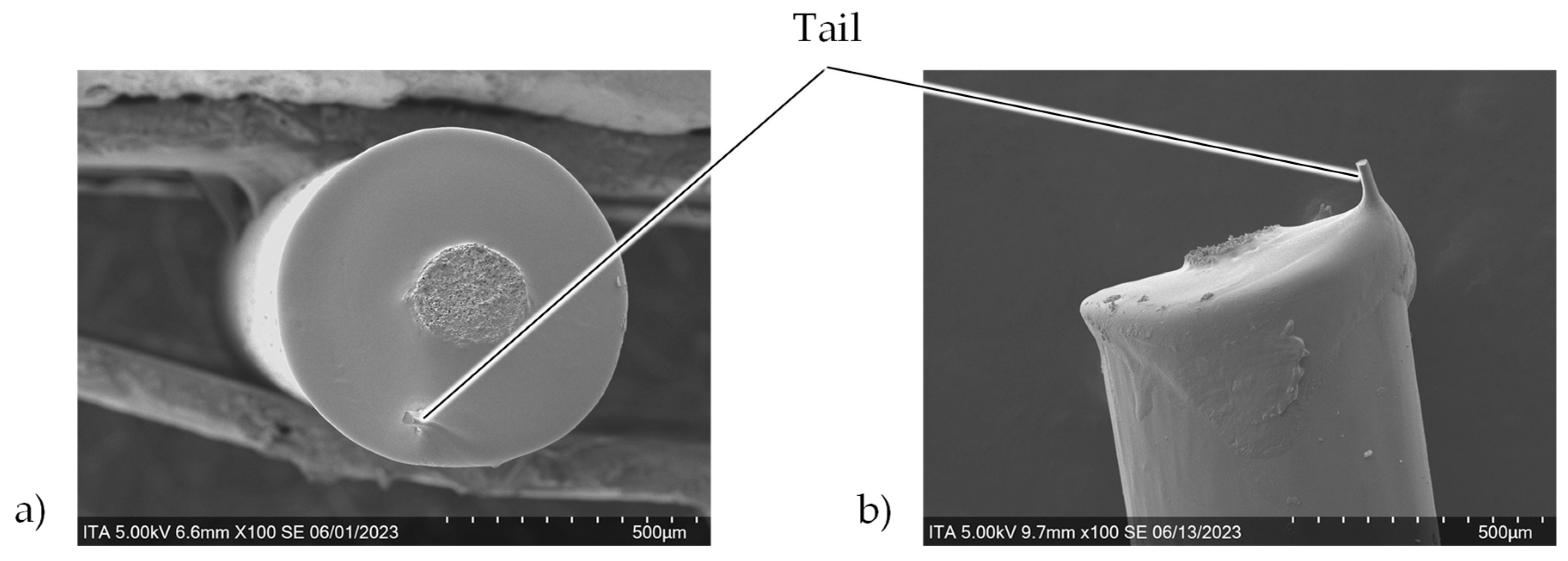
Lastly to be investigated from the cross-sectional images is the small tail visible in the samples cut at 25 mm/s and 20 W, which is also visible in the longitudinal images (
Figure 14). This may result from the relatively fast, but low energy input of the laser. There is not enough time for the sheath material to be fully and cleanly cut and the remaining “tail” is broken after cutting. This would also explain why the cutting with even higher speed was not possible at the lowest power (50 mm/s and 20 W). The even higher speed and less dwell time for cutting resulting in an uncut filament, which was visible macroscopically.
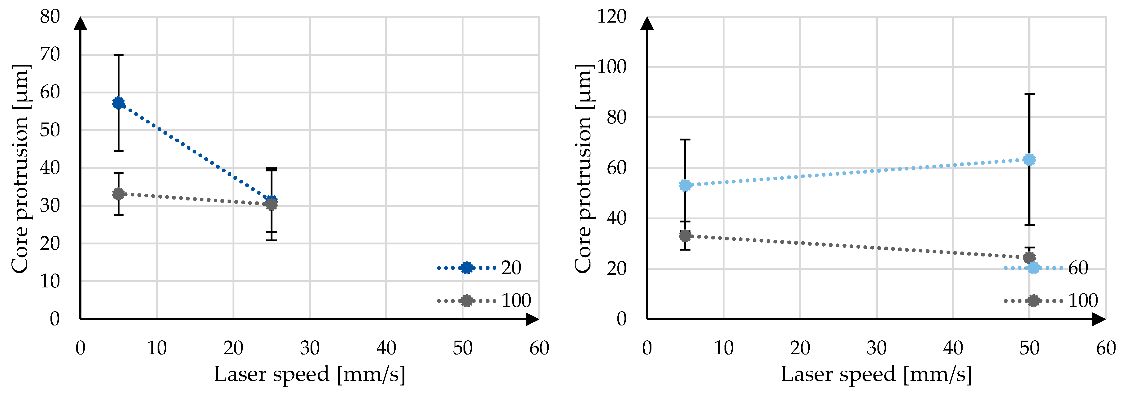
With analysis of the longitudinal images, other conclusions can be made. It can be seen that the cores of the samples cut at low speeds (5 mm/s) protrude more from the sheath than the samples cut at higher speeds (25 and 50 mm/s). This dependence of the protrusion on the laser parameters can be seen in
Figure 15.
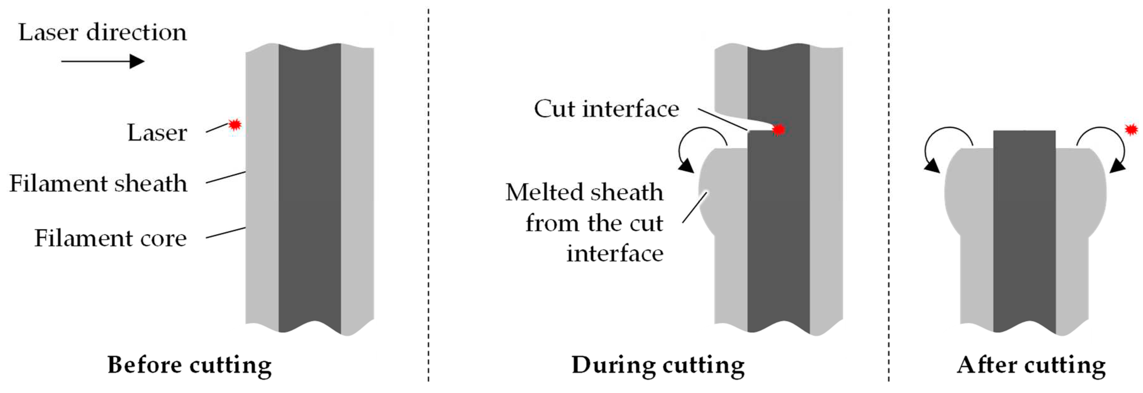
This could be explained by the melting of the sheath material during cutting. It is thought that the cut height of the laser is in line with the residual core component and not in line with the remaining sheath. The material at the cut interface is burnt away and material near the interface melts due to residual heat. This melting causes the sheath to retract and collect around the sheath. This is shown schematically in
Figure 16.
This thicker sheath near the cutting interface can be observed to different degrees for all the samples in
Figure 5. For the slower speed of 5 mm/s, however, the collection of the sheath is more prominent and, in some cases, appears to have even “dripped” down the filament. Additionally, the collection of the material seems to be more prevalent on one side of the filament. For the higher speeds, the thickening is less extreme and results in more of a diagonal cut as for the lower speed. It is hypothesized that the side of the large collection for the slow speed and the higher diagonal side for the higher speed is the bottom of the filament while cutting; the filaments are laid horizontally in the machine. Due to gravity, the melted sheath material may flow more to the lower side of the filament before resolidifying, either as the round collection or the diagonal cut. This could be further investigated by imaging filaments not fully cut or by maintaining the filament position between cutting and imaging.
4.2.2. Static electrical resistivity
In
Figure 7 it is observable that all the samples tested are relatively linear and that the data, when extrapolated to 0 cm, also tends towards 0 Ω. This is important because a non-zero y-intercept points towards either a contact resistance between the interfaces or inhomogeneous filaments and contacting method. This can be seen in
Figure 9 and
Figure 10 for the y-intercept as well as the linearity R². It can be generally said that both a lower laser speed and lower laser power lead to a smaller y-intercept. The lower speed and power additionally lead to a higher linearity, with the exception of 5 mm/s and 60 W, although the R² of 0,9881 is already very close to the ideal 1,0. Because these values, y-intercept and linearity, are calculated using all data points per sample, there is no possibility to calculate the significance with a t-test and therefore only the trend of the data, but not the significance of the data can be concluded.
Conversely, the static linear resistivity can be evaluated for both the trends and the significance of the parameter variation. Again, the trend shows that the lower laser speed and lower laser power tend towards a lower static linear resistivity average and standard deviation, whereby the difference appears more dramatic for the standard deviation. The significance of the static linear resistivity is shown in
Figure 11 with the help of a Pareto chart. In both comparison cases, both factors, laser speed (A) and laser power (B), as well as the combination of the parameters (AB) is found to be not significant. For this reason, based solely on the resulting linear resistivity, there is no evidence to select certain laser parameters. However, based on the observed trends, with keeping in mind that the difference may not be statistically significant, it is suggested to conduct further cutting and contacting of bicomponent TPU filaments with the 5 mm/s laser speed and 20 W laser power.
5. Conclusions
The motivation for this work is the trend towards digitalization in industrial applications. This required novel sensor systems, including filament formed sensors for applications in which textiles are applied, such as fiber reinforced composites, geotextiles and smart wearables. Bicomponent filaments allow the sensitive conductive core material to be protected from external influences such as moisture and wear. TPU has the advantage that the material is very flexible and variable, able to cover a wide range of applications. However, the soft nature of TPU makes the contacting of the conductive core in a bicomponent filament challenging.
In this work a cutting and contacting method for TPU core-conductive bicomponent filaments is developed. The cutting is carried out with a laser cutter, in order to avoid smearing the sheath TPU material. With silver paint and metallic crimps, the conductive area is enlarged and simultaneously protected from friction and flaking. Differences in the surface morphology of the cut samples were observed while altering the laser parameters (laser speed and laser power). However, it was found that these parameters do not have a significant influence on the resulting linear resistivity of the samples. Despite this lack of significance, it is suggested to continue cutting of the bicomponent filament with the lower laser speed (5 mm/s) and lower laser power (20 W) based on the trends of the average and standard deviation of the linear resistivity, as well as the y-intercept and linearity of the length vs. resistance trendlines.
This work serves as the starting point for much more research, as it makes the electrical analysis of TPU-bicomponent filament even possible through a stable cutting and contacting. For further work, the depth of the heat transfer into the core will be evaluated with monocomponent filaments. Additionally, the thickening of the sheath material after cutting can be investigated. Lastly, countless more filaments, with various production parameters, such as core pump speed, extrusion temperature, spinneret diameter and winding speed, can be examined. This will further the research in the development of filament based strain sensors and will give information about the dependence of the static and dynamic electrical resistivities on the spinning parameters, possibly allowing for a tailored filament for each application case.
Author Contributions
Conceptualization, J. Ortega; Data curation, Y. Li; Formal analysis, Y. Li, Funding acquisition, T. Gries; Investigation, J. Ortega, F. Krooß, Y. Li; Supervision, J. Ortega, T. Gries, Writing – original draft, J. Ortega; Writing – review & editing, J. Ortega, F. Krooß. All authors have read and agreed to the published version of the manuscript.
Funding
This research was funded by the Federal Ministry for Economy and Energy (Bundesministerium für Wirtschaft und Energie, BMWi) under the program “Central Innovation Programme for SMEs” (Zentrales Innovationsprogramm Mittelstand, ZIM), grant number KK5055907ZG0”.
Data Availability Statement
The data presented in this work are available on request from the corresponding author.
Acknowledgments
The authors would like to thank BASF Polyurethanes GmbH, Lemförde, Germany for providing the material TPU 1185 for this research.
Conflicts of Interest
The authors declare no conflict of interest. The funders had no role in the design of the study; in the collection, analyses, or interpretation of data; in the writing of the manuscript; or in the decision to publish the results.
References
- Splunk Inc. Das Datenzeitalter hat begonnen: Sind Sie bereit? 2020. Available online: https://www.splunk.com/de_de/campaigns/data-age.html.
- Roths, J.; Kratzer, P. Vergleich zwischen optischen Faser-Bragg-Gitter-Dehnungssensoren und elektrischen DehnungsmessstreifenIntercomparison of Optical FBG-based Strain Sensors and Resistive Strain Gages. Technisches Messen 2008, 75, 647–654. [Google Scholar] [CrossRef]
- Konertz, D.; Löschmann, J.; Clauß, F.; Mark, P. Faseroptische Messung von Dehnungs- und Temperaturfeldern/Fiber optic sensing of strain and temperature fields. Bauingenieur 2019, 94, 292–300. [Google Scholar] [CrossRef]
- HUESKER Synthetic GmbH. Embankments - Bridging of Sinkholes: Railway Junction Gröbers near Leipzig/Germany. 2013. Available online: https://www.huesker.us/fileadmin/media/Project_Reports/GB/JR_E_F_Embankments_Bridging_of_Sinkholes_Groebers.pdf (accessed on 20 July 2023).
- Alexiew, D.; Estêvão Ferreira da Silva, A. High-Strength Geogrids Bridging a Sinkhole: First Projet Worldwide Including Renewed Sinkhole Activity. 2006. Available online: https://www.huesker.es/fileadmin/media/Scientific_Revised_Paper/PT/09_Cobramseg_2006_-_Sink_Hole.pdf (accessed on 20 July 2023).
- van de Vel, A.; Cuppens, K.; Bonroy, B.; Milosevic, M.; Jansen, K.; van Huffel, S.; Vanrumste, B.; Cras, P.; Lagae, L.; Ceulemans, B. Non-EEG seizure detection systems and potential SUDEP prevention: State of the art: Review and update. Seizure 2016, 41, 141–153. [Google Scholar] [CrossRef] [PubMed]
- Bautista-Quijano, J.R.; Pötschke, P.; Brünig, H.; Heinrich, G. Strain sensing, electrical and mechanical properties of polycarbonate/multiwall carbon nanotube monofilament fibers fabricated by melt spinning. Polymer 2016, 82, 181–189. [Google Scholar] [CrossRef]
- Li, W.; Pei, Z. Strain-sensing fiber with a core–sheath structure based on carbon black/polyurethane composites for smart textiles. Textile Research Journal 2021, 91, 1907–1923. [Google Scholar] [CrossRef]
- He, Z.; Byun, J.-H.; Zhou, G.; Park, B.-J.; Kim, T.-H.; Lee, S.-B.; Yi, J.-W.; Um, M.-K.; Chou, T.-W. Effect of MWCNT content on the mechanical and strain-sensing performance of Thermoplastic Polyurethane composite fibers. Carbon 2019, 146, 701–708. [Google Scholar] [CrossRef]
- BASF Polyurethanes GmbH. Technical Data Sheet - Elastollan 1185 A 10 FC. 2019.
- Particle doped fiber based sensors for the monitoring of structures. In 2022 IEEE Sensors Applications Symposium, August 1-3, 2022, Sundsvall, Sweden: 2022 symposium proceedings. 2022 IEEE Sensors Applications Symposium (SAS), Sundsvall, Sweden, 8/1/2022 - 8/3/2022; IEEE: Piscataway, NJ, 2022; pp 1–6, ISBN 978-1-6654-0981-0.
- Trotec Laser GmbH. R500: Technical Specifications. 2021.
- Keithley Instruments. 2100 6 1/2 Digit Multimeter. 2023.
Figure 1.
Schematic representation of the developed core conducting, bicomponent filament.
Figure 1.
Schematic representation of the developed core conducting, bicomponent filament.
Figure 2.
Schematic of the longitudinal filament cross-section showing the electrical interfaces after contacting.
Figure 2.
Schematic of the longitudinal filament cross-section showing the electrical interfaces after contacting.
Figure 3.
Image of a cut and silver painted bicomponent filament.
Figure 3.
Image of a cut and silver painted bicomponent filament.
Figure 4.
Cross-sectional SEM images of the three cutting methods; a) razor at room temperature, b) razor after freezing, c) laser.
Figure 4.
Cross-sectional SEM images of the three cutting methods; a) razor at room temperature, b) razor after freezing, c) laser.
Figure 5.
Longitudinal SEM images of comparison of the laser parameters.
Figure 5.
Longitudinal SEM images of comparison of the laser parameters.
Figure 6.
Cross-sectional SEM images of comparison of the laser parameters.
Figure 6.
Cross-sectional SEM images of comparison of the laser parameters.
Figure 7.
Linear dependence of resistance and sample length.
Figure 7.
Linear dependence of resistance and sample length.
Figure 8.
Interaction plot linear resistivity and laser parameters.
Figure 8.
Interaction plot linear resistivity and laser parameters.
Figure 9.
Interaction plot abs. y-intercept and laser parameters.
Figure 9.
Interaction plot abs. y-intercept and laser parameters.
Figure 10.
Interaction plot linearity R² and laser parameters.
Figure 10.
Interaction plot linearity R² and laser parameters.
Figure 11.
Pareto charts of standardized effects of linear resistivity and laser parameters.
Figure 11.
Pareto charts of standardized effects of linear resistivity and laser parameters.
Figure 12.
Direct comparison of razor and laser cut samples; a) razor at room temperature, b) razor after freezing, c) laser.
Figure 12.
Direct comparison of razor and laser cut samples; a) razor at room temperature, b) razor after freezing, c) laser.
Figure 13.
Comparison of surface pattern with varied laser power at 5 mm/s; a) 20 W, b) 60 W, c) 100 W.
Figure 13.
Comparison of surface pattern with varied laser power at 5 mm/s; a) 20 W, b) 60 W, c) 100 W.
Figure 14.
Tail resulting from cutting at high speeds and low power (25 mm/s and 20 W); a) cross-sectional and b) longitudinal SEM images.
Figure 14.
Tail resulting from cutting at high speeds and low power (25 mm/s and 20 W); a) cross-sectional and b) longitudinal SEM images.
Figure 15.
Interaction plot core protrusion and laser parameters.
Figure 15.
Interaction plot core protrusion and laser parameters.
Figure 16.
Schematic representation of the laser cutting process.
Figure 16.
Schematic representation of the laser cutting process.
Table 1.
Spinning parameters for the investigated filament.
Table 1.
Spinning parameters for the investigated filament.
| Parameter |
Unit |
Value |
| Core |
Sheath |
| Extruder pressure |
bar |
30 |
30 |
| Extrusion temperature |
Zone 1 |
°C |
177,5 |
175,0 |
| Zone 2 |
187,5 |
185,0 |
| Zone 3 |
192,5 |
200,0 |
| End piece |
197,5 |
215,0 |
| Melt line |
202,5 |
220,0 |
| Pump block |
225,0 |
220,0 |
| Spinneret |
225,0 |
220,0 |
| Pump size |
cm³/min |
0,3 |
0,6 |
| Pump speed |
RPM |
6 |
20 |
| Spinneret capillary hole diameter |
mm |
1,1 |
| Spinneret capillary hole length |
mm |
2,2 |
| Godet speed 1 |
m/min |
28 |
| Godet speed 2 |
29 |
| Winding speed |
30 |
Table 2.
Features of the laser cutting machine R500 Rayjet [
12].
Table 2.
Features of the laser cutting machine R500 Rayjet [
12].
| Parameter |
Unit |
Value |
| Working area |
mm x mm |
1300 x 900 |
| Laser source |
- |
CO2
|
| Laser class |
- |
2 |
| Max. cutting speed |
m/s |
0,5 |
| Max. laser power |
W |
100 |
| Max. laser frequency |
Hz |
1000 |
| Software |
- |
Rayjet Manager |
Table 3.
Varied laser cutting parameters.
Table 3.
Varied laser cutting parameters.
| |
|
Laser power [W] |
| |
|
20 |
60 |
100 |
| Laser speed [mm/s] |
5 |
✓ |
✓ |
✓ |
| 25 |
✓ |
✓ |
✓ |
| 50 |
x |
✓ |
✓ |
|
Disclaimer/Publisher’s Note: The statements, opinions and data contained in all publications are solely those of the individual author(s) and contributor(s) and not of MDPI and/or the editor(s). MDPI and/or the editor(s) disclaim responsibility for any injury to people or property resulting from any ideas, methods, instructions or products referred to in the content. |
© 2024 by the authors. Licensee MDPI, Basel, Switzerland. This article is an open access article distributed under the terms and conditions of the Creative Commons Attribution (CC BY) license (http://creativecommons.org/licenses/by/4.0/).


