Submitted:
22 January 2024
Posted:
23 January 2024
You are already at the latest version
Abstract
Keywords:
1. Introduction
2. Materials and methods
3. Validation of the numerical simulations
4. Interface dynamics during droplet breakup
5. Model of the droplet formation
6. Conclusions
Author Contributions
Conflicts of Interest
Abbreviations
| CFD | Computational fluid dynamics |
| PIV | Particle image velocimetry |
References
- Garstecki, P.; Stone, H.A.; Whitesides, G.M. Mechanism for Flow-Rate Controlled Breakup in Confined Geometries: A Route to Monodisperse Emulsions. Physical Review Letters 2005, 94, 164501. [Google Scholar] [CrossRef] [PubMed]
- Xi, H.; Guo, W.; Leniart, M.; Chong, Z.Z.; Tan, S.H. AC electric field induced droplet deformation in a microfluidic T-junction. Lab Chip 2016. [Google Scholar] [CrossRef] [PubMed]
- Guillot, P.; Colin, A. Stability of parallel flows in a microchannel after a T junction. Phys. Rev. E 2005, 72, 066301. [Google Scholar] [CrossRef] [PubMed]
- Tan, S.H.; Nguyen, N.T.; Yobas, L.; Kang, T.G. Formation and manipulation of ferrofluid droplets at a microfluidic T-junction. Journal of Micromechanics and Microengineering 2010, 20, 045004. [Google Scholar] [CrossRef]
- Xiong, Q.; Chen, Z.; Li, S.; Wang, Y.; XU, J. Micro-PIV measurement and CFD simulation of flow field and swirling strength during droplet formation process in a coaxial microchannel. Chemical Engineering Science 2018, 185, 157–167. [Google Scholar] [CrossRef]
- Rostami, B.; Morini, G. Experimental characterisation of a micro cross-juntion as generator of Newtonian and non-Newtonian droplets in silicone oil flow at low Capillary numbers. Experimental Thermal and Fluid Science 2019, 103, 191–200. [Google Scholar] [CrossRef]
- DE MENECH, M.; GARSTECKI, P.; JOUSSE, F.; STONE, H.A. Transition from squeezing to dripping in a microfluidic T-shaped junction. Journal of Fluid Mechanics 2008, 595, 141–161. [Google Scholar] [CrossRef]
- Steegmans, M.; Schroën, K.; Boom, R. Generalised insights in droplet formation at T-junctions through statistical analysis. Chemical Engineering Science 2009, 64, 3042–3050. [Google Scholar] [CrossRef]
- Dolomite microfluidics: https://www.dolomite-microfluidics.com/.
- Chen, Q.; Jingkun, L.; Song, Y.; Christopher, D.; Li, X. Modeling of Newtonian droplet formation in power-law non-Newtonian fluids in a flow-focusing device. Heat and Mass Transfer 2020, 56. [Google Scholar] [CrossRef]
- Lindken, R.; Rossi, M.; Große, S.; Westerweel, J. Micro-particle image velocimetry (μPIV): recent developments, applications, and guidelines. Lab on a Chip 2009, 9, 2551–2567. [Google Scholar] [CrossRef] [PubMed]
- Barnkob, R.; Rossi, M. DefocusTracker: A Modular Toolbox for Defocusing-based, Single-Camera, 3D Particle Tracking. Journal of Open Research Software 2021, 9, 22. [Google Scholar] [CrossRef]
- Garstecki, P.; Fuerstman, M.J.; Stone, H.A.; Whitesides, G.M. Formation of droplets and bubbles in a microfluidic T-junction—scaling and mechanism of break-up. Lab on a Chip 2006, 6, 437. [Google Scholar] [CrossRef] [PubMed]
- Rostami, B.; Morini, G. Generation of Newtonian and non-Newtonian droplets in silicone oil flow by means of a micro cross-junction. International Journal of Multiphase Flow 2018, 105. [Google Scholar] [CrossRef]
- Yu, W.; Liu, X.; Zhao, Y.; Chen, Y. Droplet generation hydrodynamics in the microfluidic cross-junction with different junction angles. Chemical Engineering Science 2019, 203, 259–284. [Google Scholar] [CrossRef]
- Maurya, T.; Dutta, S. Pinch-off dynamics of droplet formation in microchannel flow. Chemical Engineering Science 2023, 282, 119296. [Google Scholar] [CrossRef]
- Z., L.; Y., M.; X., W.; Y., P.; Y., R.; D., L. Experimental and theoretical studies on neck thinning dynamics of droplets in cross junction microchannels. Experimental thermal and fluid science 2022, 139, 110739. [Google Scholar] [CrossRef]
- Loizou, K.; Wong, V.L.; Hewakandamby, B. Examining the Effect of Flow Rate Ratio on Droplet Generation and Regime Transition in a Microfluidic T-Junction at Constant Capillary Numbers. Inventions 2018, 3. [Google Scholar] [CrossRef]
- Liu, H.; Zhang, Y. Droplet formation in microfluidic cross-junctions. Physics of Fluids 2011, 23, 082101. [Google Scholar] [CrossRef]
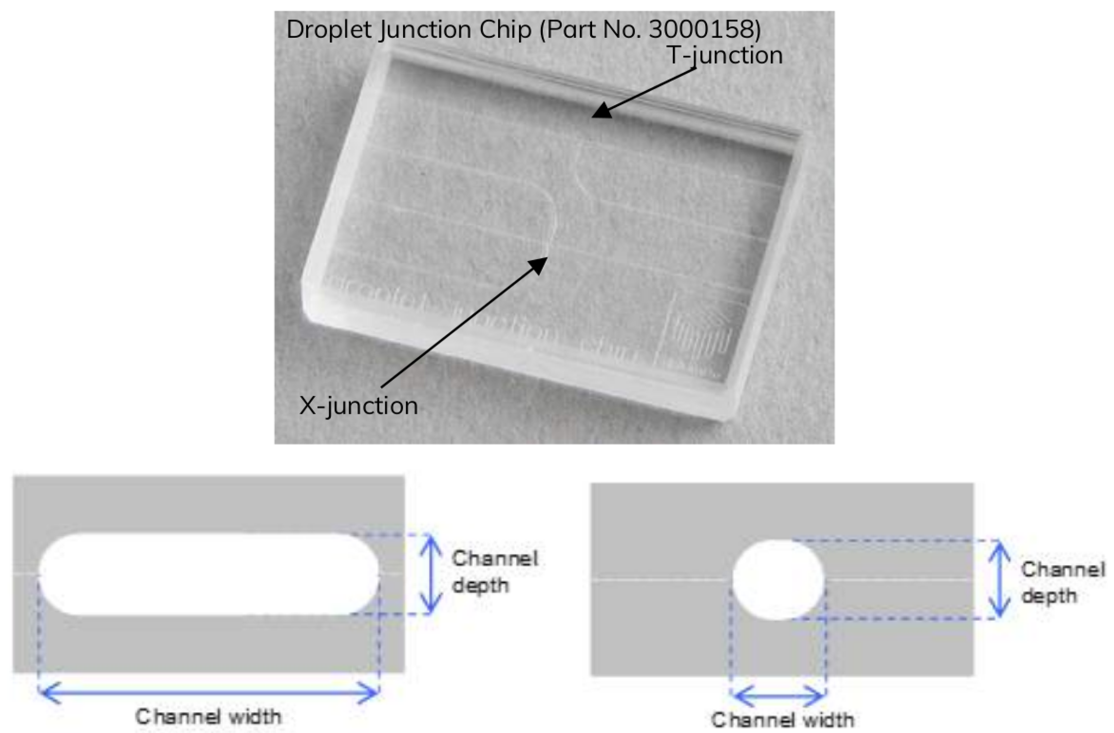
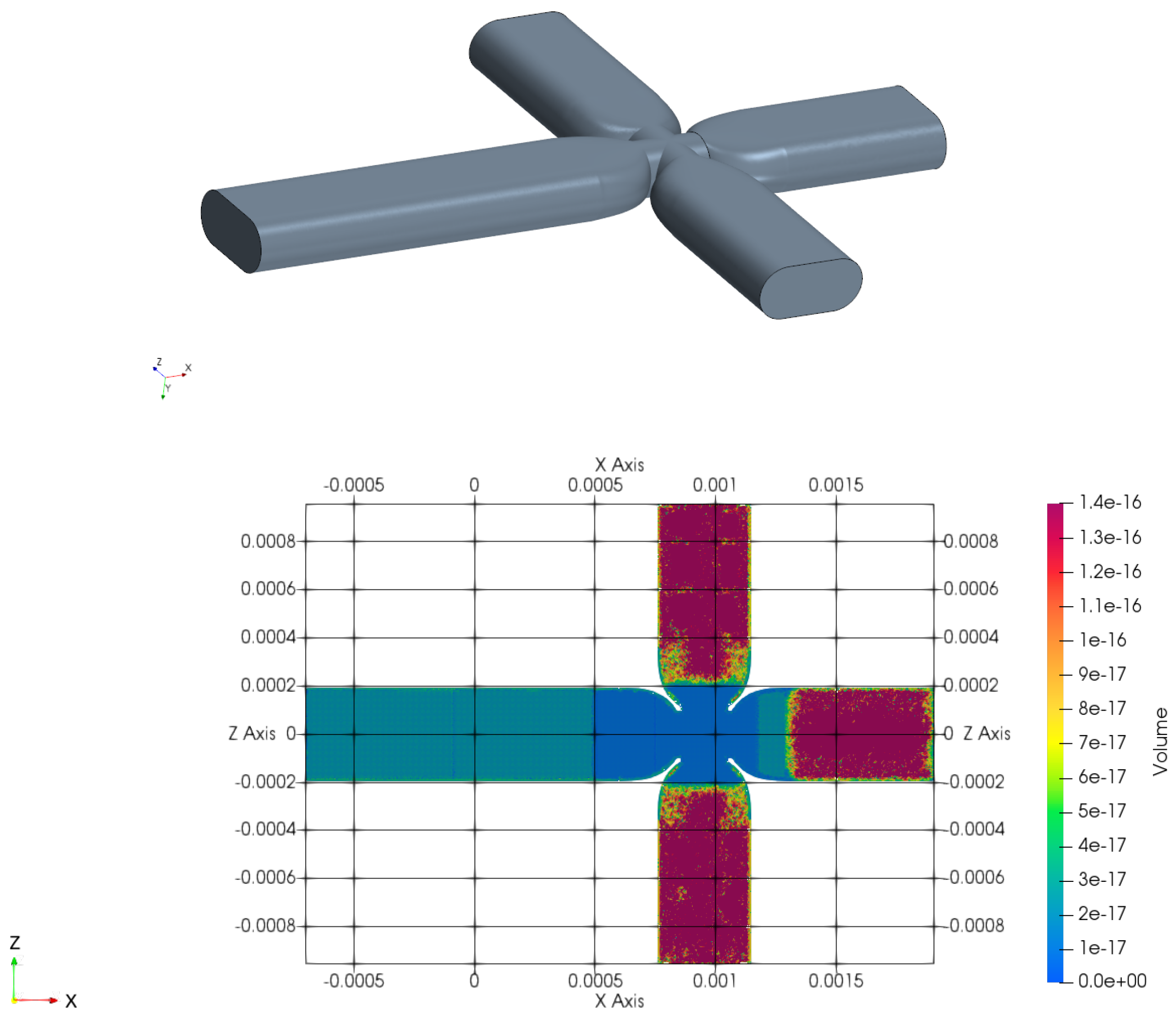
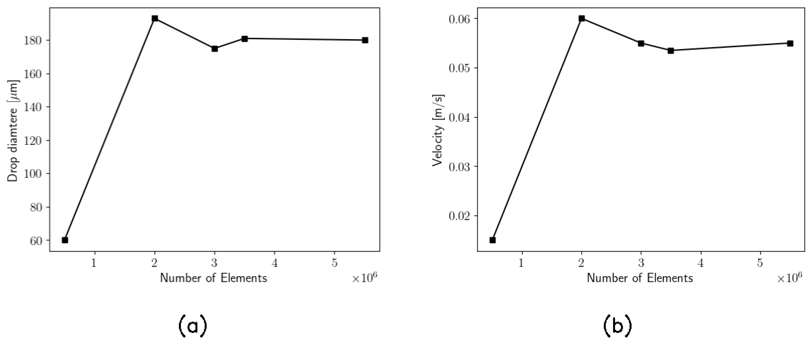
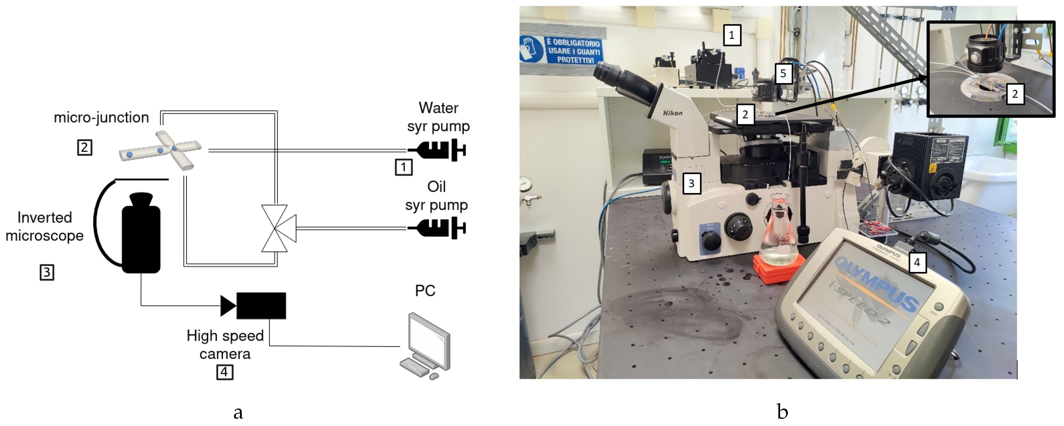


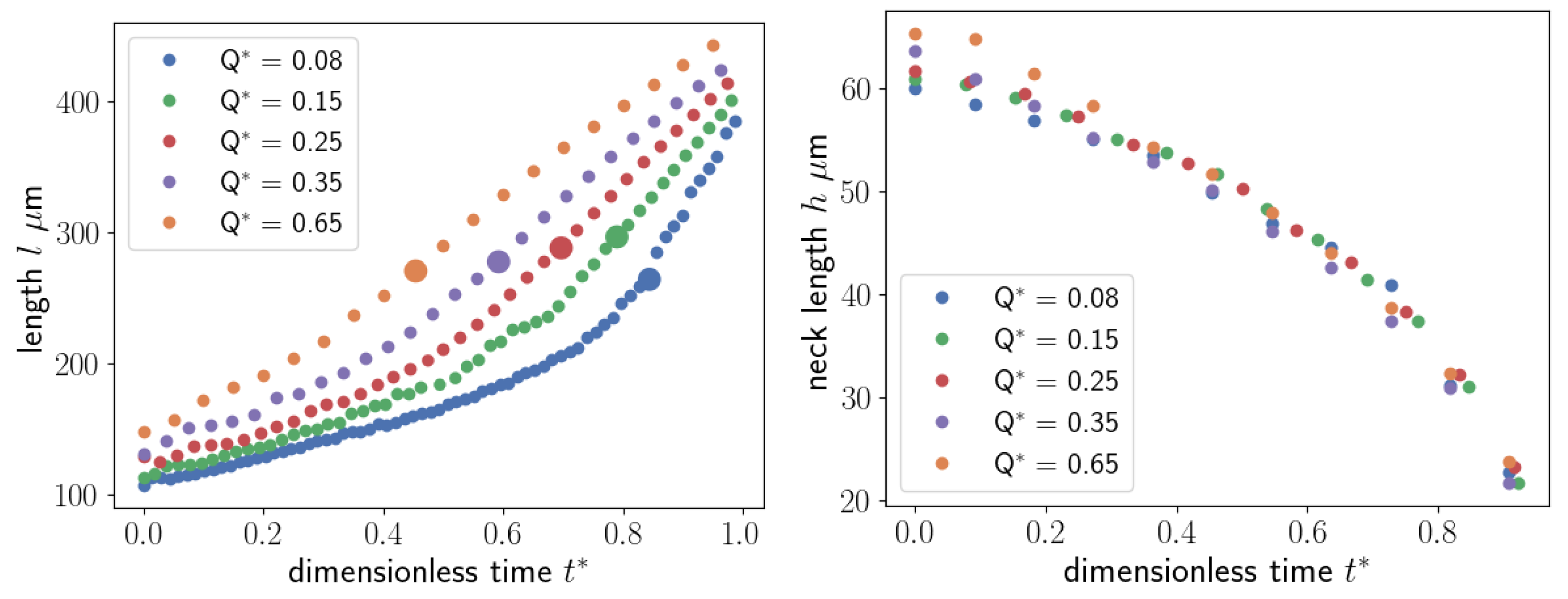
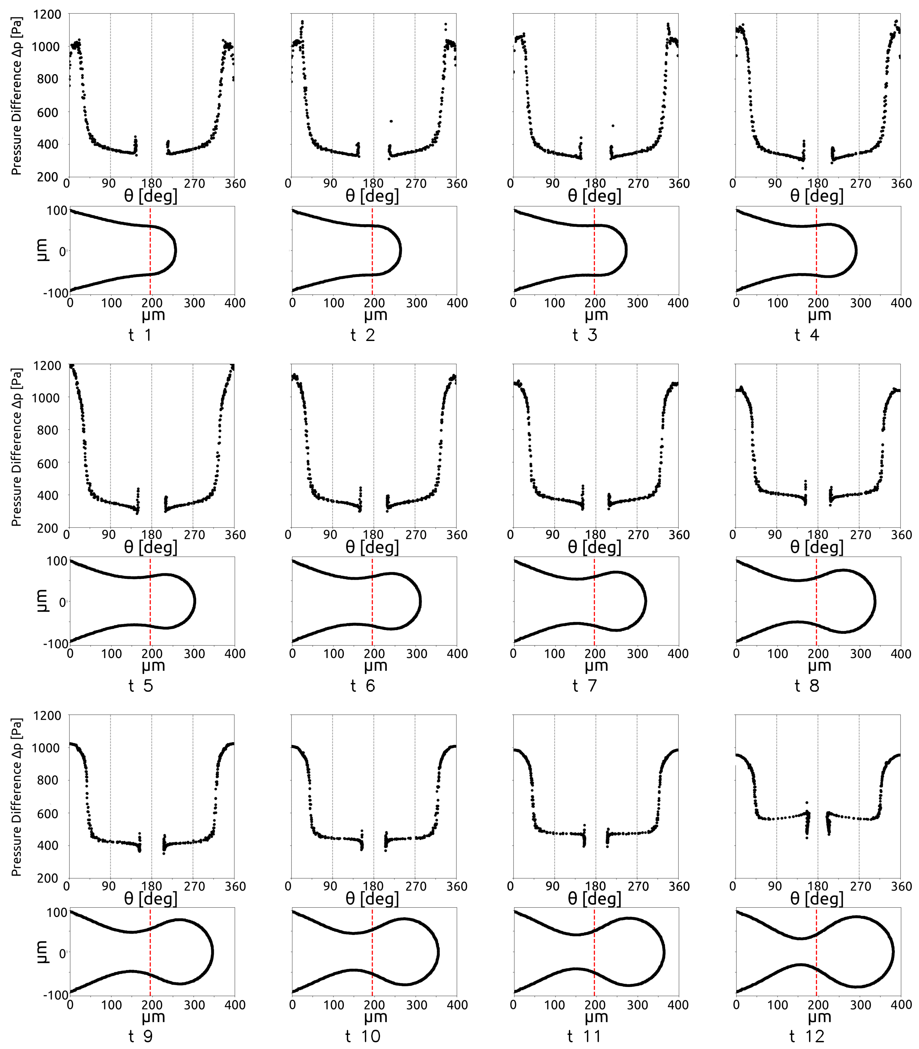
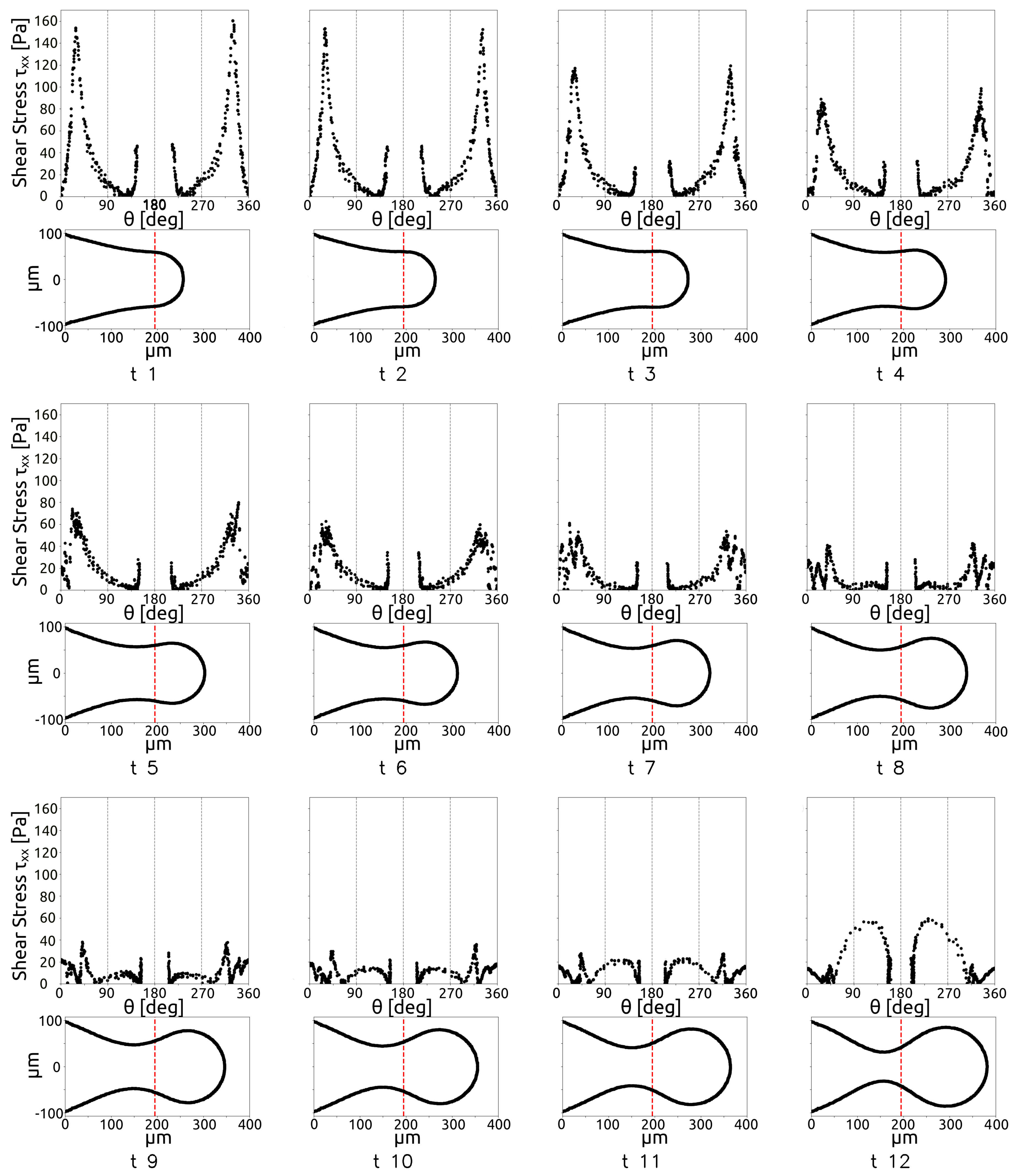
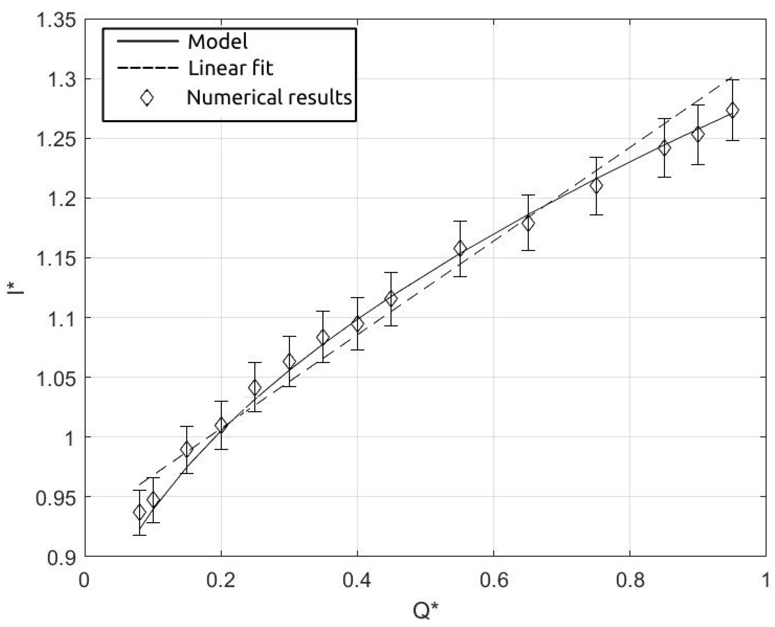
| sim. | Q* | drop length l [m] | |
|---|---|---|---|
| 1 | 0.08 | 178 | 0.913 |
| 2 | 0.10 | 180 | 0.923 |
| 3 | 0.15 | 188 | 0.964 |
| 4 | 0.20 | 192 | 0.984 |
| 5 | 0.25 | 198 | 1.015 |
| 6 | 0.30 | 202 | 1.036 |
| 7 | 0.35 | 206 | 1.056 |
| 8 | 0.40 | 208 | 1.067 |
| 9 | 0.45 | 212 | 1.087 |
| 10 | 0.55 | 222 | 1.128 |
| 11 | 0.65 | 224 | 1.149 |
| 12 | 0.75 | 230 | 1.179 |
| 13 | 0.85 | 236 | 1.210 |
| 14 | 0.90 | 238 | 1.221 |
| 15 | 0.95 | 242 | 1.241 |
Disclaimer/Publisher’s Note: The statements, opinions and data contained in all publications are solely those of the individual author(s) and contributor(s) and not of MDPI and/or the editor(s). MDPI and/or the editor(s) disclaim responsibility for any injury to people or property resulting from any ideas, methods, instructions or products referred to in the content. |
© 2024 by the authors. Licensee MDPI, Basel, Switzerland. This article is an open access article distributed under the terms and conditions of the Creative Commons Attribution (CC BY) license (http://creativecommons.org/licenses/by/4.0/).


