Submitted:
25 January 2024
Posted:
26 January 2024
You are already at the latest version
Abstract
Keywords:
1. Introduction
2. Ancient Times and Fictional References
3. Inventions in the Twentieth Century
3.1. Rotating Masses
3.2. Gyroscopes and Spinning Wheels
4. Progress in the Twenty-First Century
4.1. Theoretical Contributions
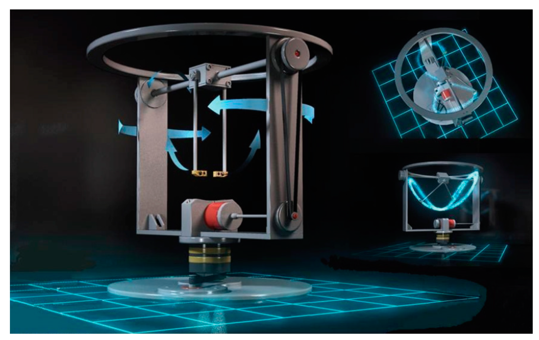
- An inertial drive attached to a vehicle or cart, which initially lies on the ground, causes alternating (sinusoidal) support forces on it. For an immobilized vehicle, the total linear momentum of the contra-rotating masses varies in time and its temporal derivative equals to the vertical support force (ground reaction exerted on the vehicle or cart). For the continuous motion of the contra-rotating masses at a constant angular velocity , external energy is generally required to withstand the friction loses [97].
- When the magnitude of the constant angular velocity, , is adequately high, the vehicle (cart) can perform a vertical jump. This happens because in the upward motion of the rotating masses (i) the reaction force is higher than the weight, and (ii) the center of mass of the system (cart + rotating masses) has an adequately large initial velocity which allows for a vertical shoot.
- An alternative explanation for the motion of the vehicle due to the attached inertial drive is as follows. In the beginning the rotating masses of the inertial drive possess a certain linear momentum toward the vertical -axis. When the orientation of the connecting rods (radii of out-of-balance masses) becomes vertical, the velocity vectors of these masses become horizontal thus the linear momentum of the rotating masses vanishes. If -for example- the angular velocity is high, the change of linear momentum per revolution () is a small percentage of the total initial value, thus practically the linear momentum of the system is preserved. Due to the said conservation of linear momentum in the vertical -axis, the lost momentum is undertaken by the vehicle. But since after 90 degrees the connecting rods will become horizontal with peak velocities, the instantaneous velocity of the vehicle vanishes, and so on.
- Obviously, if no extra energy is transmitted to the inertial drive, the initial angular velocity of the rotating masses cannot be preserved at a constant value but again the vehicle can jump [98].
- The maximum height the mechanical system “vehicle + drive” can reach depends on the initial velocity of the center of mass of this system.
- The initial velocity of the center of mass occurs when the two connecting rods to which the masses are attached are found on a horizontal position and at the same time the ground suddenly opens like the cover of a well. Then, the conservation of the linear momentum toward the vertical axis is ensured [98]. Again, it should become clear that while the vehicle stands on the ground the linear momentum is not preserved.
- Depending on the level of the initial velocity, the vehicle may elevate following an oscillating mode with the rods having performed usually a lot of revolutions, until the center of mass takes a zero value. Then the vehicle starts falling, again elevate following an oscillating mode until it takes its initial velocity in the opposite direction.
- During an extremely short time interval, it is possible to keep the vehicle immobile into the air. This phase ends when the rods which carry the rotating masses become vertical, thus the denominator of a closed-form expression vanishes, and the fraction becomes infinite [97].
- In some sense, the sinusoidal support forces are very similar to those exerted on the ground by a spring-mass system [100]. To better understand this issue, note that when the topic of oscillations is presented in high-schools or colleges, teachers say that the oscillation is the projection of a moving material point on a circle determined by the extreme positions of that oscillation.
- Therefore, the center of mass of the system performs a vertical shoot, but also an oblique shoot is possible [98].
4.2. Practical Applications
4.3. Other Patents and Broadcasts
5. A Critical Note on the Involved Mechanics in Inertial Drives
6. Discussion
7. Conclusions
Appendix A. Contra-Rotating Wipers

Appendix B. Radial Displacement of a Satellite
References
- Potier, O.N.R. The cancellation of gravity. Electronics and Power 1965, 11(3), 111. [Google Scholar] [CrossRef]
- Farrall. A.W. An Inertial Propulsion System. Transactions of the ASAE 1966, 9(4), 0586–0587. [CrossRef]
- Hancock R. (Ed.). Entry: “PROPULSION inertial”, In: The Illustrated Encyclopedia of Science and Technology: HOW IT WORKS, Marshall Cavendish Ltd, New York & London, 1977 (Vol. 14, 1874-1877). https://archive.org/details/howitworksillust14ralp/page/1874/mode/2up?q=inertial.
- Walgate, R. Eric Laithwaite defies Newton. New Scientist 1974, 14 November, p470. [Google Scholar]
- Engel, A.B.; Stiebitz, P.H. The cybernetics of inertial propulsion. Kybernetes 2009, 38(1/2), 141–157. [Google Scholar] [CrossRef]
- Fiala, H.E.; Fiala, J.E.; Fiala, J.-A. Inertial Propulsion Device to Move an Object up and Down. Patent No.: US 8.066,226 B2, Date of Patent: Nov. 29, 2011 YouTube: Harvey Fiala - Inertial Propulsion with ONLY 1 Moving Part, Extraordinary Technology Conference 2007: https://www.youtube.com/watch?v=RdxZEGPUSLI&ab_channel=TeslaTech.
- Goncharevich, I.F. Dynamics of vibrational transportation. Nauka, Moscow (1972); p. 244 [in Russian].
- Blekhman I.I., “Vibrational Mechanics: Nonlinear dynamic effects, General approach, Applications”, World Scientific, Singapore, 2000 (p.15 and p.19).
- Kononenko, V. O., Vibrating Systems with a Limited Power Supply. Iliffe Books Ltd: London, 1969, p.24 (in English). Translated from Russian: V. O. Kononenko, Oscillatory Systems with Limited Excitation. Moscow, Nauka, 1964.
- Blekhman, I.I. Synchronization in Science and Technology. ASME Press: New York, 1988 (in English, translated from Russian 1981).
- Majewski. T. Vibratory Forces and Synchronization in Physical Systems. Ingeniería Mecánica Tecnología y Desarrollo 2013, 4(4), 119–128.
- Chen, L.; Pei, Z.; Tang, Z. Maximum power control of gyroscopic wave energy converter, E3S Web Conf. 2019, 118 02022. [CrossRef]
- Townsend, N.; Shenoi, A. A gyroscopic wave energy recovery system for marine vessels. IEEE J. Oceanic Eng. 2012, 37(2), 271–80. [Google Scholar] [CrossRef]
- Tajmar M. Advanced Space Propulsion Systems. Springer: New York-Wien, 2002.
- Bruno, C.; Accettura, A.G. (Eds.) Advanced propulsion systems and technologies: Today to 2020, Volume 223 Progress in Astronautics and Aeronautics, American Institute of Aeronautics and Astronautics, Virginia, 2008.
- Millis, M.G.; Thomas, N.E. Responding to Mechanical Antigravity, NASA/TM-2006-214390, AIAA-2006-4913, December 2006. Available at: http://gltrs.grc.nasa.gov/reports/2006/TM-2006-214390.pdf.
- ElSheimy, N.; Youssef, A. Inertial sensors technologies for navigation applications: state of the art and future trends Satellite Navigation 2020, 1 Article number 2. [CrossRef]
- Lawerance, A. Modern Inertial Technologies: Navigation, Guidance and Control. Springer: New York, 1992.
- Rimrott, F.P.J. Introductory Attitude Dynamics. Springer: New York, 1989.
- Minetti, A.E.; Ardigó, L.P. Halteres used in ancient Olympic long jump. Nature 2002, 420, 141–142. [Google Scholar] [CrossRef] [PubMed]
- Provatidis, C.G. Simplified biomechanics for a possible explanation of the ancient Greek long jump using halteres. Universal Journal of Engineering Science 2013, 1(1), 5–16. [Google Scholar] [CrossRef]
- Provatidis, C.G. On the maximum length of standing long jump using halters. International Journal Multidisciplinary Research and Studies 2018, 1(3), 153–169. [Google Scholar]
- Citizendium: http://en.citizendium.org/wiki/Reactionless_propulsion.
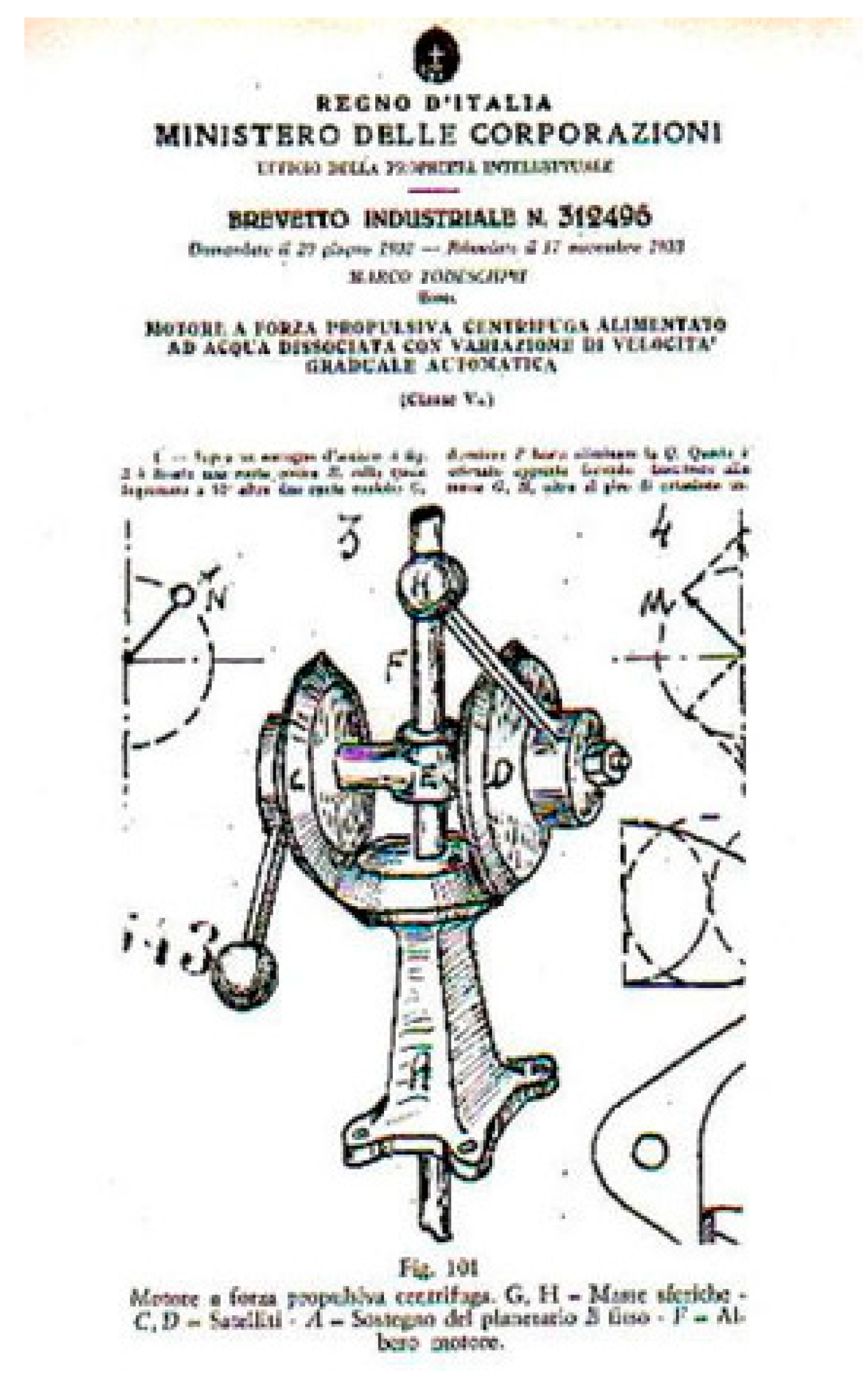
- Todeschini M. Motore a forza propulsive centrifuga alimentato ad acqua dissociate con variazione di velocita graduale automatic. Regno d’Italia, Ministero delle Corporazioni, Brevetto Industriale No. 312496, 17 November 1933 (see the first two pages of the patent at the website www.circolotodeschini.com).
- Dean N.L. System for converting rotary motion into unidirectional motion. US Patent 2,886,976, May 19, 1959.
- Dean, N.L. Variable oscillator system. US Patent 3,182,517, May 11, 1965.
- Campbell, J., Jr. The Space Drive Problem. Astounding Science Fact and Fiction, 19 June; 83–106.
- Dempewolff, R.F. Engine with Built-in Wings,” Popular Mechanics, Sept. 1961, 131–134 and 264-266.
- Burridge, G. Toward Antigravity,” Rosicrucian Digest, Vol. XL, April 1962, 136–139.
- Davis, W.O. The Fourth Law of Motion, Analog 69(3): 83-104 (May 1962). Extract is available at: http://www.rexresearch.com/dean/davis4.htm.
- Stine, G.H. Detesters, Phasers and Dean Drives,” Analog, June 1976, 75.
- Campbell, J.W. (1962) - Interview by Fred Lerner: https://www.youtube.com/watch?v=SC-o9z-E010&ab_channel=FANACFanHistory.
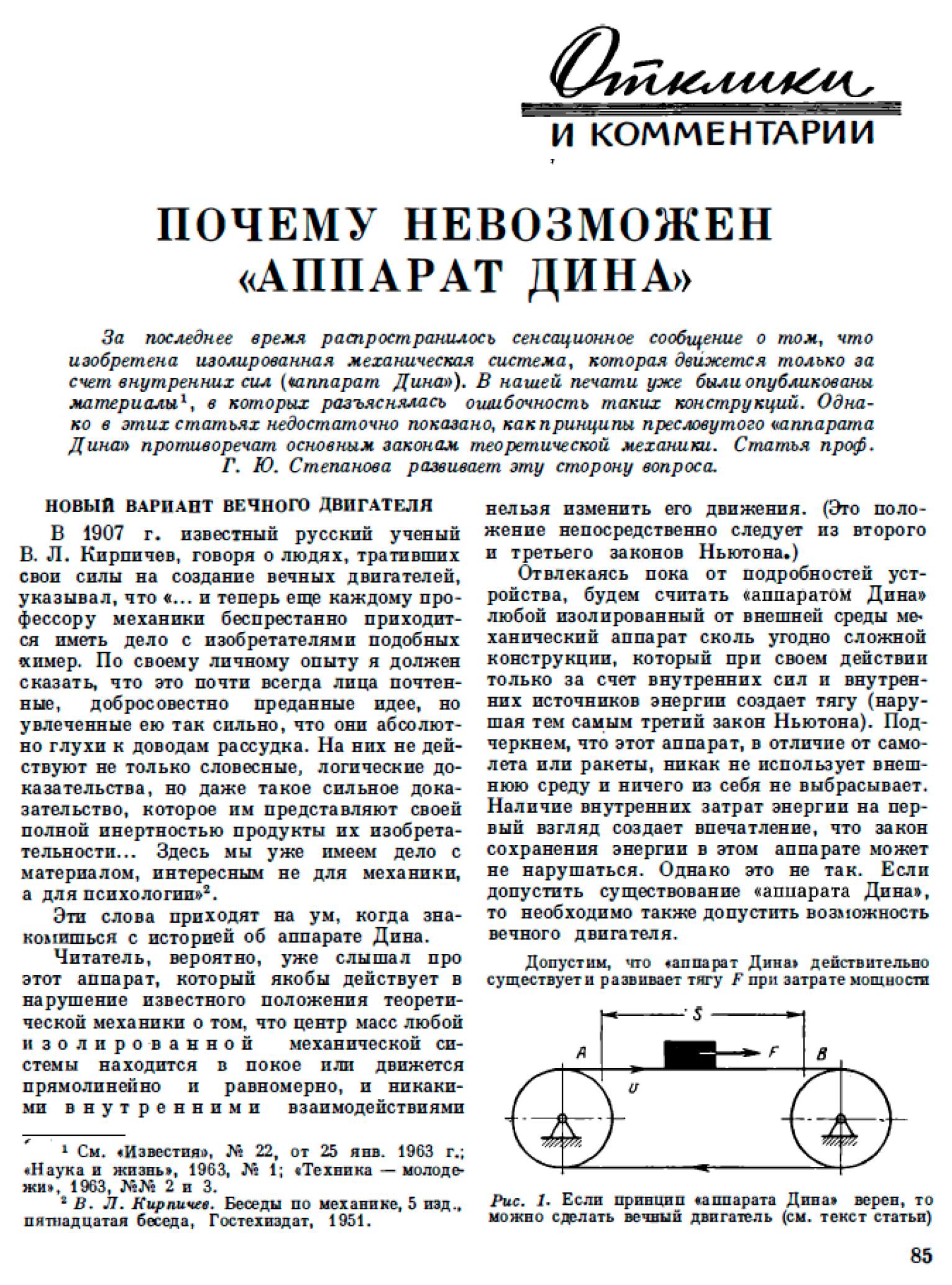
- Stepanov, G.Yu. , “Why is it impossible to have ‘Dean’s Apparatus’?,” Jour. Priroda, vol. 7, 1963, pp. 85-91 (in Russian).
- Di Bella, A. Apparatus for imparting motion to a body, US Patent 3,404,854 (filed on May 5, 1967 and granted on Oct. 8, 1968).
- Di Bella, A. On propulsive effects of a rotating mass. In: R. D. Cooper, and S. W. Doroff (Eds.), Proceedings Seventh Symposium Naval Hydrodynamics, August 25-30, 1968, Rome, Italy (Office of Naval Research -Department of The Navy, Arlington, Va.), pp. 1373-1396.
- Online: https://en.wikipedia.org/wiki/Viviani%27s_curve.
- Therriault, C. Wing movement for ornithopters and apparatus of the like, US Patent No. 6,227,483 B1, May 8, 2001.
- Kuchinov, E. Quesalid’s Knots: A Guide to the Soviet Union’s Esoteric Research Institutes. https://sreda.v-a-c.org/en/read-01.
- Tolchin, V.N. Sily inertsii kak istochnik postupatel’nogo dvizheniia (Perm: Permskoe knizhnoe izdatel’stvo, 1977). Translation: Forces of inertia as a source of translational motion.
- Tolchin Drive-Short Original Film Copy: https://www.youtube.com/watch?v=DOXoaYs790M&ab_channel=stclairtechrd https://www.youtube.com/watch?
- Laithwaite, E.R. Propulsion without wheels, 2nd edition. English Universities Press: London, 1970.
- Wikipedia: https://en.wikipedia.org/wiki/Eric_Laithwaite.
- Laithwaite, E.R. The engineer through the looking glass | The Royal Institution: Science Lives Here. Retrieved 7 January 2024. (https://www.rigb.org/explore-science/explore/video/engineer-through-looking-glass-looking-glass-house-1974).
- Bruce De Palma: https://en-academic.com/dic.nsf/enwiki/1876830. 1876.
- DePalma, B. The Tuning Fork Experiment, In: R.L. Dione, 1976 (ISBN 553-02723-150); see also: http://www.brucedepalma.com/n-machine/spinning-ball-experiment/.
- http://rexresearch.com/depalma2/depalm.htm.
- https://depalma.pairsite.com/gyrodrop.html.
- Hayasaka, H.; Takeuchi, S. Anomalous weight reduction on a gyroscope’s right rotations around the vertical axis on the earth. Physical Review Letters 1989, 63(25), 2701–2704. [Google Scholar] [CrossRef]
- Adelberger, E.G. Science correspondence on paper by Hayasaka & Takeuchi. Nature 1990, 345, 121. [Google Scholar]
- Faller, J. E.; Hollander, W.J.; Nelson, P.G.; McHugh, M.P. Gyroscope-weighing experiment with a null result. Phys Rev Lett 1990, 64, 825–826. [Google Scholar] [CrossRef] [PubMed]
- MacCallum, M. Does a spinning mass really lose weight? New Scientist 1990, N1704, 30. [Google Scholar]
- Nitschke, J.M.; Wilmarth, P.A. Null result for the weight change of a spinning gyroscope. Phys Rev Lett 1990, 64, 2115–2116. [Google Scholar] [CrossRef] [PubMed]
- Quinn, T.J.; Picard, A. The mass of spinning rotors: no dependence on speed or sense of rotation. Nature 1990, 343, 732–735. [Google Scholar] [CrossRef]
- Salter, S.H. Good vibrations for physics. Nature 1990, 343, 509–510. [Google Scholar] [CrossRef]
- Imanishi, A.; Maruyama, K.; Midorikawa, S.; Morimoto, T. Observation against the weight-reduction of spinning gyroscopes. Journal of the Physical Society of Japan 1991, 60, 1150–1152. [Google Scholar] [CrossRef]
- Hayasaka, H.; Tanaka, H.; Hashida, T.; Chubachi, T.; Sugiyama, T. Possibility for the existence of anti-gravity: evidence from a free-fall experiment using a spinning gyro. Speculations in Science and Technology 1997, 20, 173–181. [Google Scholar]
- Luo, J.; Nie, Y.X.; Zhang, Y.Z.; Zhou, Z.B. Null result for violation of the equivalence principle with the free-fall rotating gyroscopes, Phys. Rev. D 2002, 65, 042005. [Google Scholar] [CrossRef]
- Labeysh, V.G. Experiments on Asymmetrical Mechanics. Galilean Electrodynamics 2000, 11, 8–11. [Google Scholar]
- Dmitriev A., L. and Snegov V. S.. Measurements of mass: the weighing of a mechanical gyroscope with horizontal and vertical orientation of the spin axis. Measurement Techniques 2001, 44(8), 831–833, (Translated from Izmeritel’naya Tekhnika, No. 8, pp. 33–35, August, 2001. Original article submitted April 3, 2001). [Google Scholar] [CrossRef]
- Dmitriev A., L. Frequency Dependence of Rotor’s Free Falling Acceleration and Inequality of Inertial and Gravity Masse. January 2011, arXiv:1101.4678 [pdf].
- Dmitriev, A.L.; Snegov, V.S. Measurements of mass: the weighing of a mechanical gyroscope with horizontal and vertical orientation of the spin axis. Measurement Techniques 2001, 44, 831–833. [Google Scholar] [CrossRef]
- Dmitriev, A.L. Physical substantiation of an opportunity of artificial change of body weight. Physics Procedia 2012, 38, 150–163. [Google Scholar] [CrossRef]
- Dmitriev, A.L. Prospects of high-frequency gravimetry. International Journal of Circuits, Systems and Signal Processing 2015, 9, 275–280, Online at: https://www.inase.org/library/2015/vienna/bypaper/APNE/APNE-37.pdf. [Google Scholar]
- Provatidis, C.G. Free fall of a symmetrical gyroscope in vacuum. European Journal of Physics 2021, 42, 065011. [Google Scholar] [CrossRef]
- Wayte, R. The phenomenon of weight-reduction of a spinning wheel. Meccanica 2007, 42, 359–364. [Google Scholar] [CrossRef]
- Lőrincz, I.; Tajmar, M. Identification of error sources in high precision weight measurements of gyroscopes. Measurement 2015, 73, 453–461. [Google Scholar] [CrossRef]
- Provatidis, Forced precession in a spinning wheel supported on a rotating pivot, Mechanics Research Communications 2013, 52, 46– 51. [CrossRef]
- Provatidis, C.G. Forced precession of a gyroscope with application to the Laithwaite’s engine. European Journal of Physics 2021, 42(3). [Google Scholar] [CrossRef]
- Allen, J.E. Quest for a novel force: a possible revolution in aerospace. Progress in Aerospace Sciences 2003, 39(1), 1–60. [Google Scholar] [CrossRef]
- Meek, J. BAe’s anti-gravity research braves X-Files ridicule. The Guardian, Mon 27 Mar 2000. Online: https://www.theguardian.com/science/2000/mar/27/uknews.
- Anonymous. Project Greenglow and the battle with gravity. News, 23 March 2016, https://www.bbc.com/news/magazine-35861334. See als, https://www.documentaryarea.com/video/Project%20Greenglow%20The%20Quest%20for%20Gravity%20Control/.
- Interview from Ron Evans: https://www.youtube.com/watch?v=BwI7Ij-5cMA&ab_channel=TimVentura.
- Anonymous. Science Does The Impossible: February 2003 Cover Story. Popular Mechanics. https://archive.ph/20070930015205/http://www.popularmechanics.com/science/research/1282281.html?page=3.
- Anonymous, Boeing Internal Report Looks At Propellentless Propulsion, https://www.spacedaily.com/news/rocketscience-02t.html.
- BBC-News, Boeing tries to defy gravity. Monday, 29 July, 2002. http://news.bbc.co.uk/2/hi/science/nature/2157975.stm.
- Wikipedia: Eugene Podkletnov. https://en.wikipedia.org/wiki/Eugene_Podkletnov#cite_note-8.
- Millis, M.G. Breakthrough Propulsion Physics Research Program. NASA Technical Memorandum 107381. December 199.
- Millis, M.G. NASA breakthrough propulsion physics program. Acta Astronautica 1999, 44(2-4), 175–182. [Google Scholar] [CrossRef]
- Millis, M.G. Assessing Potential Propulsion Breakthroughs. Annuals of New York Academy of Sciences 2005, 1065, 441–461. [Google Scholar] [CrossRef] [PubMed]
- Millis, M.G.; Davis, E.W. Frontiers of Propulsion Science. American Institute of Aeronautics and Astronautics Inc.: Reston, VA, 2009.
- Millis, M.G. Progress in revolutionary propulsion physics, Paper IAC-10-C4.8.7. In: Proceedings 61st International Astronautical Congress, Prague CZ, 2010.
- Hoshino M., U.S. Patent for “Propulsion apparatus using centrifugal force,” No. 20050139022 (Filed 7 Jan. 2004; Published: 30 June 2005).
- Hampton, S.M., From Dean Drives and Davis Mechanics: Inertial Propulsion and the Manipulation of Time in Symmetrical Systems ©, Ebook, Apple Communications, London Mills, Illinois, 2007, 2011 (ISBN 518 373).
- Hampton, S.M. Asymmetric Impulse Drive. AIAA 2022-4391. ASCEND 2022 (24-26 October 2022, Las Vegas, Nevada & Online). Session: Frontiers in Deep Space Propulsion. View Video Presentation. [CrossRef]
- Tsiriggakis, V.Th.; Provatidis C.G.; Frigas S. U.S. Patent Application for an “Antigravity Mechanism,” No. 61/110,307, filed 31 Oct. 2008.
- Provatidis, C.G.; Tsiriggakis, V.T. A new concept and design aspects of an ‘antigravity’ propulsion mechanism based on inertial forces. Proceedings of 46th AIAA/ASME/SAE/ASEE Joint Propulsion Conference & Exhibit, Nashville, TN, 25-28 July 2010 (Paper AIAA 2010-6684).
- Provatidis, C.G. A device that can produce net impulse using rotating masses. Engineering 2020, 2(8), 648–657. [Google Scholar] [CrossRef]
- Pipes, L.A.; Harville, L.R. Applied mathematics for engineers and physicists, 3rd ed. McGraw-Hill: New York, 1981, pp. 494–496.
- Provatidis, C.G.; Gamble, M.A. Support forces in a synchronized rotating spring-mass system and its electromagnetic equivalent. International Journal of Applied Electromagnetics and Mechanics 2013, 41(3), 313–333. [Google Scholar] [CrossRef]
- Manning, J. Space, Propulsion & Energy Sciences International Forum-A Journalist’s Notes, Infinite Energy (May/June) 2012, May-June, Issue 103, 18-23.
- Valone, T. Inertial Propulsion: Concept and Experiment, Part I, Proc. IECEC, 1993.
- Valone, T. Inertial Propulsion: Concept and Experiment, Part II, Intersociety Energy Conversion Engineering Conference (07 August 1994 - 12 August 1994, Monterey, CA, U.S.A), AIAA-94-4167-CP, pp. 1484-1489. [CrossRef]
- Valone, T.; Cox, J. Inertial Propulsion: Patent Collection. Integrity Research Institute: Washington, D.C., 2008.
- Valone, T.F. Eric Laithwaite Report: Gyromagnetic Engineering Genius – Publications, Inventions & News Clips (IRI PR-02-005), Integrity Research Institute: Beltsville, MD, December, 2006.
- Almesallmy, M. Experimental and Analytical Investigation of Inertial Propulsion Mechanisms and Motion Simulation of Rigid-Multi-Body Mechanical Systems. PhD Dissertation. University of Rhode Island, 2006.
- Guiad, D.; Nilvetti, F.; Pappalardo, C.M. Dry Friction Influence on Cart Pendulum Dynamics. International Journal of Mechanics 2009, 3(2), 31–38. [Google Scholar]
- Provatidis, C.G. Some issues on inertia propulsion mechanisms using two contra-rotating masses. Theory of Mechanisms and Machines 2010, 8(1), 34–41, Download from: http://tmm.spbstu.ru/15/Provatidis_15.pdf. [Google Scholar]
- Provatidis, C.G. A study of the mechanics of an oscillating mechanism, International Journal of Mechanics 2011, 5(4), 263-274. Online at: https://www.naun.org/main/NAUN/mechanics/17-093.pdf.
- Provatidis, C.G. An overview of the mechanics of oscillating mechanisms. American Journal of Mechanical Engineering 2013, 1(3), 58–65. [Google Scholar] [CrossRef]
- Provatidis, C.G. Repeated vibrational motion using an inertial drive. Vibration and Acoustics Research Journal 2019, 1(1). Online: https://www.cansrg.com/journals/varj/2019/70.pdf.
- Provatidis, C.G. On the inertial propulsion of floating objects using contra-rotating masses. Mechanics Research Communications 2014, 62, 117–122. [Google Scholar] [CrossRef]
- Ikuta, K., Aritomi, S. and Kabashima, T. Tiny silent linear cybernetic actuator driven by piezoelectric device with electromagnetic clamp. [1992] Proceedings IEEE Micro Electro Mechanical Systems, Travemunde, Germany, 1992, pp. 232-237. [CrossRef]
- Aoyama, H., Iwata, F. and Sasaki, A. Desktop flexible manufacturing system by movable miniature robots-miniature robots with micro tool and sensor. Proceedings of 1995 IEEE International Conference on Robotics and Automation, Nagoya, Japan, 1995, pp. 660-665 vol.1. [CrossRef]
- Zesch, W.; Buchi, R.; Codourey, A.; Siegwart, R. Inertial Drives for Micro- and Nanorobots: Two Novel Mechanisms. Proc. SPIE Microrobotics and Micromechanical Systems, Philadelphia, USA, pp. 80-88, 18 October 1995. [CrossRef]
- Buchi, R.; Zesch, W.; Codourey, A.; Siegwart, R. Inertial Drives for Micro- and Nanorobots: Analytical Study. Proc. SPIE Vol. 2593, p. 89-97, Microrobotics and Micromechanical Systems, 1995. [CrossRef]
- Yoshikawa, H.; Kagiwada, T.; Harada, H.; Mimura, M. Improvement of Propulsion Mechanism Based on the Inertial Force. In: F. Kimura and K. Horio (Eds.), Towards Synthesis of Micro-/Nano-Systems. Springer: London, 2007, pp. 333-334.
- Ju, J.; Wang, Q.; Zhang, K. Design and analysis of a novel micro-robot driving platform. Proc IMechE-Part C: Journal of Mechanical Engineering Science 2019, 233, 3849–3857. [Google Scholar] [CrossRef]
- Vatholomeos, P.; Papadopoulos, E. Dynamics, design and simulation of a novel micro-robotic platform employing vibration micro-actuators. ASME Journal of Dynamic Systems, Measurement and Control 2006, 128, 122–133. [Google Scholar] [CrossRef]
- Vartholomeos, P.; Papadopoulos, E. Analysis and experiments on the force capabilities of centripetal-force-actuated microrobotic platforms. IEEE Transactions on Robotics 2008, 24, 588–599. [Google Scholar] [CrossRef]
- Provatidis, C.G. Design of a propulsion cycle for endless sliding on frictional ground using rotating masses. Universal Journal of Mechanical Engineering 2014, 2 (2), 35 – 43. [CrossRef]
- Provatidis, C.G. Mechanics of Dean drive on frictional ground, Journal of Mechanical Design and Vibration 2014, 1(1), 10-19. Online at: https://pubs.sciepub.com/jmdv/1/1/3/index.html. [CrossRef]
- Provatidis, C.G. Unidirectional motion using rotating masses along figure-eight-shaped trajectories, Journal of the Brazilian Society of Mechanical Sciences and Engineering 2015, 37(1), 397–409. [CrossRef]
- Provatidis, C.G. Progress in an Antigravity Mechanism using Inertial Masses. Proceedings Space, Propulsion & Energy Sciences International Forum (SPESIF-2011) [CR-ROM], presented on March 15-17, 2011, University of Maryland, College Park, MD, USA.
- Provatidis, C.G. Older and contemporary attempts for inertial propulsion. The General Science Journal, 14 November 2011. Online: http://gsjournal.net/Science-Journals/Essays/View/3772.
- Gamble, M. History of Boeing Control Moment Gyros (CMG). Presentation in Seventh International Conference On Future Energy (COFE7), July 30 – August 1, 2015, Embassy Suites, Albuquerque New Mexico (Boeing 15-00051-EOT).
- Gamble, M. Linear Propulsion. Presentation in Seventh International Conference On Future Energy (COFE7), July 30 – August 1, 2015, Embassy Suites, Albuquerque New Mexico.
- Samokhvalov, V.N. Research on, and Measurement of, Force Effects During Mass-Dynamic Interaction. Galilean Electrodynamics & GED East 2015, 26, 3–11. [Google Scholar]
- Samokhvalov, V.N. Non-electromagnetic force interaction in presence of rotating masses in vacuum. International Journal of Unconventional Science 2016, Issue E1, 68-80. http://www.unconv-science.org/en/e1/samokhvalov/. /.
- Allen, D.P. Jr.; Dunning-Davies, J. Neo-Newtonian Mechanics with Extension to Relativistic Velocities; Part 1: Non-Radiative Effects, 18 th Ed., Kindle Direct Publishing, 2023. Part 1.
- Milković, V. Gravitational Machines: from Leonardo da Vinci to the latest discoveries. Veljko Milkovic Research & Development Center: Novi Sad, Serbia, 2013 (ISBN 978-86-88883-03-0).
- Allen, D.P.; Provatidis, C.G. Inclined large-angle pendulum may produce endless linear motion of a cart when friction is negligible. WSEAS Transactions on Applied and Theoretical Mechanics 2022, 17, Art. #23, p.184-197. Online: https://wseas.com/journals/mechanics/2022/a465111-016(2022).pdf. [CrossRef]
- Provatidis, C. Teaching the Fixed Spinning Top Using Four Alternative Formulations. WSEAS Transactions on Advances in Engineering Education 2021, 18, 80–95. [Google Scholar] [CrossRef]
- Provatidis, C.G. Revisiting the Spinning Top. International Journal of Materials and Mechanical Engineering 2012, 1, 71–88, Online at: https://www.academia.edu/27516500/Revisiting_the_Spinning_Top. [Google Scholar]
- Loukanov, I.A. Vibration Propulsion of a Mobile Robot. IOSR Journal of Mechanical and Civil Engineering 2015, 12, 23–33, www.iosrjournals.org. Online: https://www.academia.edu/65248904/Vibration_Propulsion_of_a_Mobile_Robot. [Google Scholar]
- Loukanov, I.A. Application of Inertial Forces for generating Unidirectional Motion. Proceedings of the Scientific Conference of University of Rousse 2014, 53(2). Online https://www.researchgate.net/publication/314067949_Application_of_Inertial_Forces_for_Generating_Unidirectional_Motion.
- Loukanov, I.A.; Uziak, J. Upon Improving the Prediction of the Flow Rate of Sonic Pump. International Journal of Engineering Research and Applications 2013, 3, 393–398, Online: https://www.ijera.com/papers/Vol3_issue1/BF31393398.pdf. [Google Scholar]
- Lukanov, I.A.; Vitliemov, V.G.; Ivanov, I.V. Dynamics of a Mobile Mechanical System with Vibration Propulsion (VibroBot). International Journal of Research in Engineering and Science (IJRES) 2016, 4, 44–51. [Google Scholar]
- Cook, R.L. Device for Conversion of Centrifugal Force to Linear Force and Motion, US Patent 4,238,968, granted December 16, 1980.
- Thornson, B.R. Apparatus for developing a propulsion force. United States Patent No. 4,631,971 (Filed: 25.05.84; Awarded: 30.12.1986).
- Foster, R.E. Converting rotary motion into unidirectional motion. United States Patent No. 3653269, 1972.
- Robertson, D.B. Propulsion method and apparatus utilizing centrifugal force. World Intellectual Property Organization (WIPO), Number WO 01/46584 A3, 28 June 2001.
- Chung, T.B. Internal propulsion apparatus of closed system using a Coriolis force. International Patent WO 03/087574 A1, 23 (Filing date: 08 April 2003; Publication date: 23 October 2003).
- Tanner, M.A. Resonant Maglev Centrifugal Propulsion. United States Patent Application US 2007/0079663 A1 (Filed: 12 Aug. 2006; Published: 12 Apr. 2007).
- Farrall, A.W. (1966), “Inertial propulsion device”, United States Patent No. US3266233A (associated to reference [2]).
- Robertson, G.A.; Murad, P.A.; Davis, E. New Frontiers in Space Propulsion Sciences. Energy and Conversion Management 2008, 49, 436–452. [Google Scholar] [CrossRef]
- Robertson, G.A.; Webb, D.W. The Death of Rocket Science in the 21st Century. Physics Procedia 2011, 20, 319–330. [Google Scholar] [CrossRef]
- Die Schwunge Maschine: http://www.zdf.de/ZDFmediathek/hauptnavigation/startseite/#/beitrag/video/1573468/Die-Schwung-Maschine.
- Hilscher, G. Trägheit der Masse mobilisiert die Energietechnik: Mit dem findigen Johann Klimpfinger auf Entdeckungstour durch Archive und seine experimentelle Welt. NET-Journal 2011, 16(3/4), 46-50. Online: http://www.borderlands.de/net_pdf/NET0311S46-50.pdf.
- Anonymous, Kreisel Präzessions Antrieb (Gyro Precession Drive), Online at: https://www.youtube.com/watch?v=nstIIZZadAM&ab_channel=gyro2012.
- Stoney, W. Method of propulsion. Irish Patent Application. IE 20190160 A2. Date of Publication of Application: 03.08.2022 Journal No. 2469.
- Myshkin, N.P. “Dvizheniye tela, nakhod yashegosya v potoke luchistoi energii.” //Zhyrnal Russkogo fiziko-himicheskogo obshestva, 1906, v.3, p.149. (Russian) (“The movement of object placed in the radiant energy flow.”).
- Kozyrev, N.A. “Prichinnaya ili nesimmetrichnaya mekhanika v lineinom priblizhenii.”, Pulkovo, GAO AN SSSR, 1958, 90 p. (Russian) (“Causal or asymmetrical mechanics in linear approximation.”).
- Kozyrev, N.A. “On the possibility of experimental investigation of the properties of time.” //Time in science and philosophy, Prague, 1971, p.111-132.
- http://shipov.com/science.html; http://shipov.com/gennady-i-shipov/.
- Wikipedia: https://en.wikipedia.org/wiki/Torsion_field_(pseudoscience).
- Linevich, E.I.; Ezshov, A.F. The inertial motor. New Energy Technologies 2004, 3, 12–15. [Google Scholar]
- Kouznetsov, D. Support of non-traditional concepts. Far East Journal of Mechanical Engineering and Physics 2010, 1, 1–6, Online: https://www.pphmj.com/abstract/5076.htm. [Google Scholar]
- Tim Ventura & Dr. Gennady Shipov, Inertial Propulsion in Russia: Dr. Gennady Shipov on Torsion Physics & Inertial Propulsion, Interview to American Antigravity.Com, 2012, pp. 1-8 (http://shipov.com/files/200506_news09.pdf; http://einsteinandtesla.com/files/200506_news09.pdf).
- V. Sorokin: http://www.ntv.ru/novosti/84720/video.
- Alex Naumov. Russian scientists test perpetual motion machine in space. PRAVDA Newspaper, 14.04.2009. Accessed on 22nd January 2024: http://english.pravda.ru/science/tech/14-04-2009/107399-russian_scientists-0. /.
- Wikipedia: https://en.citizendium.org/wiki/Valery_Menshikov.
- Wikipedia: http://en.wikipedia.org/wiki/Yubileiny.
- Zhao, C.; Zhu, H.; Zhang, Y. Synchronization of two coupled exciters in a vibrating system of spatial motion. Acta Mechanica Sinica 2010, 26, 477–493. [Google Scholar] [CrossRef]
- Zhao, C.; Zhang, Y.; Wen, B. Synchronisation and general dynamic symmetry of a vibrating system with two exciters rotating in opposite directions. Chin Phys B 2010, 19, 030305-1-7. [Google Scholar] [CrossRef]
- Chen, X.; Liu, J.; Li, L. Dynamics of the Vibration System Driven by Three Homodromy Eccentric Rotors Using Control Synchronization, Appl. Sci. 2021, 11. [Google Scholar] [CrossRef]
- Hambling, D. EmDrive: China’s radical new space drive, Wired 06.02.2013 (https://www.wired.co.uk/article/emdrive-and-cold-fusion).
- Halliday, D.; Resnick, R. Physics. Wiley: NY, International Edition, pp.59-61, 1966.
- Casey, J. Geometrical derivation of Lagrange’s equations for a system of particles. American Journal of Physics 1994, 62, 836–847. [Google Scholar] [CrossRef]
- Casey, J. Applying the principle of angular momentum to constrained systems of point masses. American Journal of Physics 2014, 82, 165–168. [Google Scholar] [CrossRef]
- Laithwaite E 1994 Heretics BBC2 Television London; plus private demonstrations and Imperial College Christmas Lectures available in internet (e.g. http://youtube.com/watch?v&tnqx3d; KnNUTOxHoto), Accessed 04.04.2020.
- Laithwaite, E.; Dawson, W. Propulsion System. US Patent No. 5,860,317 (grant Jan.1999).
- Pinheiro, M.J. On Newton’s third law and its symmetry-breaking effects. Physica Scripta 2010, 84(5), 055004. [Google Scholar] [CrossRef]
- Gutsche, G.J. Inertial Propulsion; and you thought you knew everything about physics. CreateSpace Independent Publishing Platform (November 26, 2018).
- Gutsche, G.J. Device for efficient self -contained inertial vehicular propulsion. United States Patent, Patent No .: US 9,995,284 B1, Date of Patent : Jun . 12 , 2018.
- Allen D.P., Jr. Foundations of Gutschian Mechanics: Part 1: Basics. Kindle Direct Publishing; 6th edition (November 29, 2019).
- Provatidis, C.G. A Review on Antigravity, Levitation, Resonance, and Devices Inspired by the Ouroboros Serpent. The Rose+Croix Journal 2012, 9, 18–47, Online at: https://www.academia.edu/download/50150834/vol9_18_47_provatidis.pdf. [Google Scholar]
- Manning, J. Escape from Gravity: Is the Ancient Promise of Freedom from the Pull of Earth Alive and Well at NASA and Elsewhere? In: J. Douglas Kenyon (Ed.), Forbidden Science: From Ancient Technologies to Free Energy, Chapter 13.
- Gerjuoy, E. On Newton’s third law and the conservation of momentum. American Journal of Physics 1949, 17, 477–482. [Google Scholar] [CrossRef]
- Martins, A.A.; Pinheiro, M.J. On the nature of the propulsive force of asymmetric capacitors in the atmosphere. Physics Procedia 2011, 20, 103–111. [Google Scholar] [CrossRef]
- Martins, A.A.; Pinheiro, M.J. On the nature of the propulsive force of asymmetric capacitors in a vacuum. Physics Procedia 2011, 20, 112–119. [Google Scholar] [CrossRef]
- Stephenson A 1908 XX. On induced stability London Edinburgh Dublin Phil. Mag. J. Sci. 15 233–6.
- Kapitsa, P.L. Dynamic stability of the pendulum when the point of suspension is oscillating. J. Exp. Theor. Phys. 1951, 21, 588–597. (in Russian). [Google Scholar]
- Blekhman I I, Dresig H and Shishkina E 2004 On the theory of the Indian magic rope Selected Topics in Vibrational Mechanics ed I I Blekhman (Singapore: World Scientific) pp 139–49. W.
- Cross R 2014 Laithwaite’s heavy spinning disk demonstration Phys. Teach. 52 349.
- Davidowsky P and Rogers M 2015 Debunking a video on YouTube as an authentic research experience Phys. Teach. 53 304–6.
- Sheheitli, H. On the dynamics of a spinning top under high-frequency excitation: part I—pivot point under vertical harmonic vibration. Nonlinear Dyn 2017, 90, 765–779. [Google Scholar] [CrossRef]
- Sheheitli, H. 2017 On the dynamics of a spinning top under high-frequency excitation. Part II: pivot point under horizontal harmonic vibration Nonlinear Dyn. 2017, 90, 2269–2276. [Google Scholar] [CrossRef]
- LaViolette, P.A. Secrets of Antigravity Propulsion: Tesla, UFOs, and Classified Aerospace Technology. Bear & Company: Rochester, Vermont, 2008.
- Childress, D.H. The Antigravity Handbook, 3rd edn. Adventures Unlimited Press: Kampton-Illinois, 2010.
- Passaro, V.M.N.; Cuccovillo, A.; Vaiani, L.; De Carlo, M; Campanella, C.E. Gyroscope technology and applications: a review in the industrial perspective. Sensors 2017, 17(10), 2284. [CrossRef] [PubMed]
- Usubamatov, R. Theory of Gyroscopic Effects for Rotating Objects: Gyroscopic Effects and Applications. Springer: Cham, 2020. [CrossRef]
- Shipov, G. Four-dimensional gyroscope, demonstrating the violation of the momentum conservation law during the absolute electic collision with the wall. US20040166482A1, United States, Application filed on 2001-02-15.
- Solomon, B.T. An introduction to gravity modification: A guide to using Laithwaite’s and Podkletnov’s experiments and the physics of forces for empirical results, 2nd ed. Universal-Publishers: Boca Raton, 2012 [Chapter 5: The Laithwaite Effect, pp. 67-81, as well as §14.5 (pp. 309-315) and §14.6 (pp. 315-326)].
- Solomon, B.T. Gravitational acceleration without mass and noninertia fields. Physics Essays 2011, 24, 327–337. [Google Scholar] [CrossRef]
- Bjerke, E.; Pehrsson, B. Development of a Nonlinear Mechatronic Cube: The Jumping and Balancing Cube. Master of Science Thesis, Department of Signal and Systems, Division of Automatic control, Automation and Mechatronics, Chalmers University of Technology, Gothenburg, Sweden 2016.
- Elliott, D.S. Momentum Control Systems and their Application in Robotic Systems. PhD thesis, Cornell University, December 2019.
- Elliott, D.S.; Peck, M.; Nesnas, I.A.D. Optimal Solution for Torque Capability of Control Moment Gyroscopes. Proc. IEEE Aerospace Conference, Big Sky, MT, USA, 2019, pp. 1-17. [CrossRef]
- Elliott, D.S.; Peck, M.A. Dynamics and Control of Polyhedral Surface Robots with Control Moment Gyroscopes, Proc. AIAA Guidance, Navigation, and Control Conference, 9 - 13 January 2017. Grapevine, Texas, AIAA 2017-1050, Session: Spacecraft Robotics. [CrossRef]
- CMG-rover: NASA has supported researchers in Cornell University to develop technologies to use it for locomotion purposes (say) in Mars: https://www.spacecraftresearch.com/cmg-rover; https://www.nasa.gov/directorates/spacetech/strg/nstrf2016/Polyhedral_Rover/.
- M. Gajamohan, M. Merz, I. Thommen, and R. D’Andrea, The Cubli: a cube that can jump up, balance, and ‘walk’, In: Proc. IROS (Algavre, Portugal), pp. 3722-3727, October 2012.
- NASA’s Helical Engine and Other Reactionless Drives: https://www.youtube.com/watch?v=yNro9yiVZno&t=3s&ab_channel=PhysicsUnsimplified.
- Gyroscopic Precession Powered Car: https://www.youtube.com/watch?v=zOGlHC56Brs&t=4s&ab_channel=anisotropicplus (accompanied by 12 more movies).
- YouTube: Falcon Space Demonstrates Gyroscopic Propellentless Propulsion (Part 2): https://www.youtube.com/watch?v=OPPnmAFcPiw&ab_channel=CharlieC.
- Raptis, Y.; Kourouklis, G.A. A Tribute to the Work of the Late Professor Evangelos Anastassakis (1938-2000). physica status solidi (b) 2001, 223, 1–13. [Google Scholar] [CrossRef]
- Ünker, F.; Çuvalci, O. Gyroscopic inertial thruster (GIT), In: U.E.Solmaz, N, Kaya, and F. Ozturk, Proceedings 9th International Automotive Technologies Congress, OTEKON 2018, pp. 686-695.
- Gerocs, A.; Gillich, G.-R.; Nedelcu, D.; Korka, Z.-I. A multibody inertial propulsion drive with symmetrically placed balls rotating on eccentric trajectories. Symmetry 2020, 12, 1422. [Google Scholar] [CrossRef]
- Gerocs, A.; Korka, Z.-I.; Biró, I.; Cojocaru, V. Analytical investigation of an inertial propulsion system using rotating masses. J. Phys.: Conf. Ser. 1426 012031 (2020).
- Gerocs, A.; Korka, Z.-I; Biró, I.; Cojocaru, V. Analytical investigation of an inertial propulsion system using rotating masses. Journal of Physics: Conference Series, vol. 1426 012031. International Conference on Applied Sciences 9–11 May 2019, Hunedoara, Romania. [CrossRef]
- Sprenger, A.R.; Scholz; C., Ldov, A. et al. Inertial self-propelled particles in anisotropic environments. Commun Phys 6, 301 (2023). [CrossRef]
- Frolov, A.V. italic>New Aerospace Technologies. Independent Publisher: St.-Petersburg, Russia, 2017 (ISBN 978-5-7679-3883-4).
- McCulloch, M.E. Low-acceleration dwarf galaxies as tests of quantised inertia. Astrophys Space Sci 2017, 362: 57. [CrossRef]
- McCulloch, M.E. Physics from the edge: a new cosmological model for inertia. World Scientific: Singapore, 2014.
- McCulloch, M.E. Can the Podkletnov effect be explained by quantised inertia? Physics Procedia 2011, 20, 134–139. [Google Scholar] [CrossRef]
- Goebel, D.M.; Katz, I. Fundamentals of Electric Propulsion: Ion and Hall Thrusters. Wiley: New Jersey, 2008.
- Forward, R. L. Guidelines to Antigravity. American Journal of Physics 1963, 31, 166–170. [Google Scholar] [CrossRef]
- Mashhoon, B.; Hehl, F.W.; Theiss, D.S. On the gravitational effects of rotating masses: The Thirring-Lense papers. General Relativity and Gravitation 1984, 16, 711–750. [Google Scholar] [CrossRef]
- Tajmar, M. Homopolar artificial gravity generator based on frame-dragging. Acta Astronautica 2010, 66((9-10)), 1297–1301. [Google Scholar] [CrossRef]
- Millis, M.G. Inertial frames and breakthrough propulsion physics. Acta Astronautica 2017, 138, 85–94. [Google Scholar] [CrossRef]
- Wisdom, J. Swimming in spacetime: motion by cyclic changes in body shape. Science 2023, 299(5614), 1865–1869. [Google Scholar] [CrossRef]


Disclaimer/Publisher’s Note: The statements, opinions and data contained in all publications are solely those of the individual author(s) and contributor(s) and not of MDPI and/or the editor(s). MDPI and/or the editor(s) disclaim responsibility for any injury to people or property resulting from any ideas, methods, instructions or products referred to in the content. |
© 2024 by the authors. Licensee MDPI, Basel, Switzerland. This article is an open access article distributed under the terms and conditions of the Creative Commons Attribution (CC BY) license (http://creativecommons.org/licenses/by/4.0/).
