1. Introduction
Pipes or tubes carrying fluid play a critical role in a wide range of industrial and engineering applications, including fuel pipelines, inkjet print-head nozzles, fuel-carrying tubes in space shuttle engines, and heat exchangers in nuclear power plants; thus, forced tube conveying is clearly desired [
1,
2]. It is also worth noting that feedback control for beams might be used for forced tube vibration [
3]. From a theoretical standpoint, the fluid/structure interaction associated with the boundary moving condition remains one of the most interesting and challenging problems in dynamical systems. For over 50 years, these issues have been studied both theoretically and empirically. The challenges investigated range from changes in the natural frequencies of the pipe system caused by flowing fluid, to vibrations caused by turbulent flows, and instabilities such as flutter instability (via a Hopf bifurcation) which occurs when the flow velocity reaches a critical velocity [
4]. Following [
5], there are two aspects of forced vibration of pipes conveying fluid: the first is the physical aspect, which sheds light on the dynamics of the system, and the second is related to the analytical techniques that can be used to obtain the forced response of such systems. The latter is the focus of this work, although the results could also be extended to the first aspect.
This paper develops an improved analytical strategy based on Green’s function method to generate closed form solutions of tube carrying fluid that have continuous derivatives and satisfy the tube governing equations. Additionally, the method does not involve solving the free vibration problem in order to obtain the eigenvalues and related eigenfunctions, which are required when utilizing classical Galerskin’s method.
2. Tube Conducting Fluid General Equation of Motion
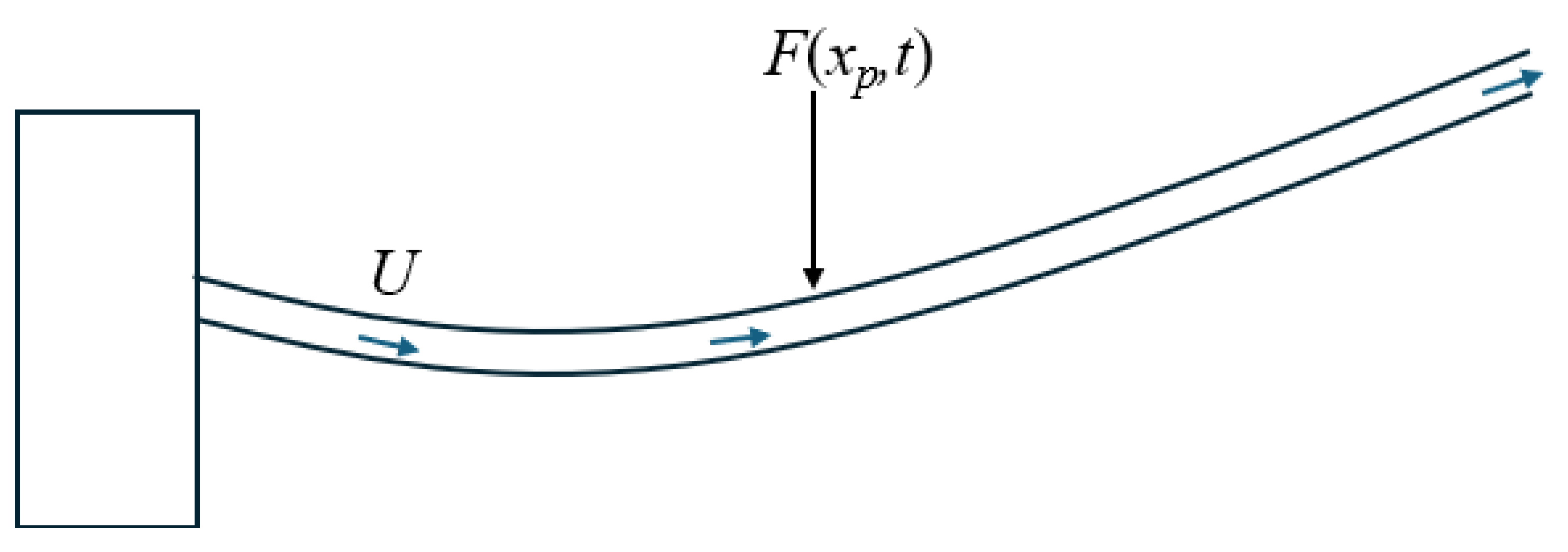
The system under consideration is a straight cantilever tube fixed to the
x-axis. The fluid with an average velocity of
U enters the tube at the fixed end and departs at the free end. A force is provided to the tube, allowing it to move transversely as depicted in
Figure 1. Furthermore, the force that induces tube motion is assumed to be harmonic. Unlike the unconstrained pipe dynamical stability achieved by many others [
5,
6], the goal here is considerably different in the sense that we want to know the precise deflection of the tube, with the harmonic force considered either distributed or concentrated.
Neglecting the effects of dissipation and damping, the general equation of motion for a tube conveying fluid can be formulated based on the following assumptions: (i) the tube has a uniform annular cross-section; (ii) the length of the tube is significantly greater than its diameter; (iii) the effects of rotary inertia and shear deformation are neglected; (iv) the tube’s center line is inextensible; (v) the tube is elastic and initially straight; and (vi) cross-sections of the tube remain plane and perpendicular to the axis of the beam, in accordance with Bernoulli-Euler beam theory. The equation can be expressed as follows [
1,
7]:
where
is the flexural rigidity of the beam,
is the mass per unit length of the fluid,
is the mass per unit length of the beam, and
is the applied force as a function of position and time.
3. Exact Analytical Solution
We propose a new approach based on Green’s function method to solve Eq.
1. Assuming the applied force is harmonic, we could formulate the problem in a complex form. Let’s consider a tube subjected to an arbitrary harmonic force, such that it is governed by an equation of the form,
The method of Green’s function is known to solve PDEs. The Green function is the solution of the equation subject to a unit impulse. The technique can be applied as follows; we consider the equation
where
is a linear differential operator,
is known whereas
is the unknown function.
We assume that we can solve the following equation:
We then deduce the Green function
solution of (
3) as :
Knowing that
and using the linearity of (
2), one obtains:
In the following this result will be applied to solve the equation of motion of a forced tube conveying fluid.
Since the applied force is harmonic, the point force is taken as
, where
is the amplitude of the force and
is the frequency. For convenience, we will formulate the problem in a complex form with
The solution of our problem is sought as :
In fact the solution is the real part of
. By replacing (
8) in (
1), we obtain
where
,
and
, which solution is given by
where we determine the Green’s function by solving the following equation:
which is performed by adopting the Laplace transform and its inverse, we then deduce,
where
is the Heaviside or step function,
and
,
, are the solutions of the following polynomial equation:
This equation can be analytically solved using Ferrari’s method.
Let
be the function defined as:
We then can write (
12) in the following form:
The last step is now to find the different boundary conditions. For this purpose we use the boundary conditions for the cantilever tube, at the fixed end (
), the deflection
is zero, i.e.,
, and the slope
. At the free end (
), both the bending moment
and the shear force
are zero. Applying this to Eq. (
16) leads to:
where we use the fact that
along the tube thus leading to
and
.
Solving the previous equations (
17) & (
18) leads to determine the unknown boundary conditions:
Finally, we can deduce the Green’s function of a tube conveying fluid as:
Using Eq.
10, we can finally establish the analytical solution of a tube conveying a fluid with a constant flow rate submitted to a punctual harmonic excitation as:
where
is given by:
4. Model Validation
We will validate the model by comparison with the series solutions, which are only valid for a tube without fluid. It is worth noting that the cantilevered beam subjected to a pointwise force can be solved analytically, and the summary of the solution is provided below with the point force represented as
Using separation of variables, the analytical solution can be written as:
This represents the response of the empty tube (or cantilevered beam) in terms of its mode shapes (Eigenfunctions)
and natural frequencies
,
with the natural frequencies,
obtained from the characteristic equation:
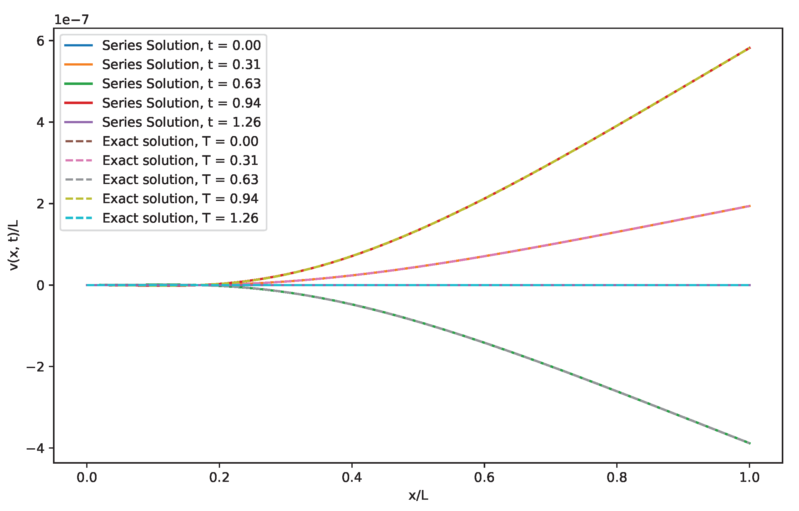
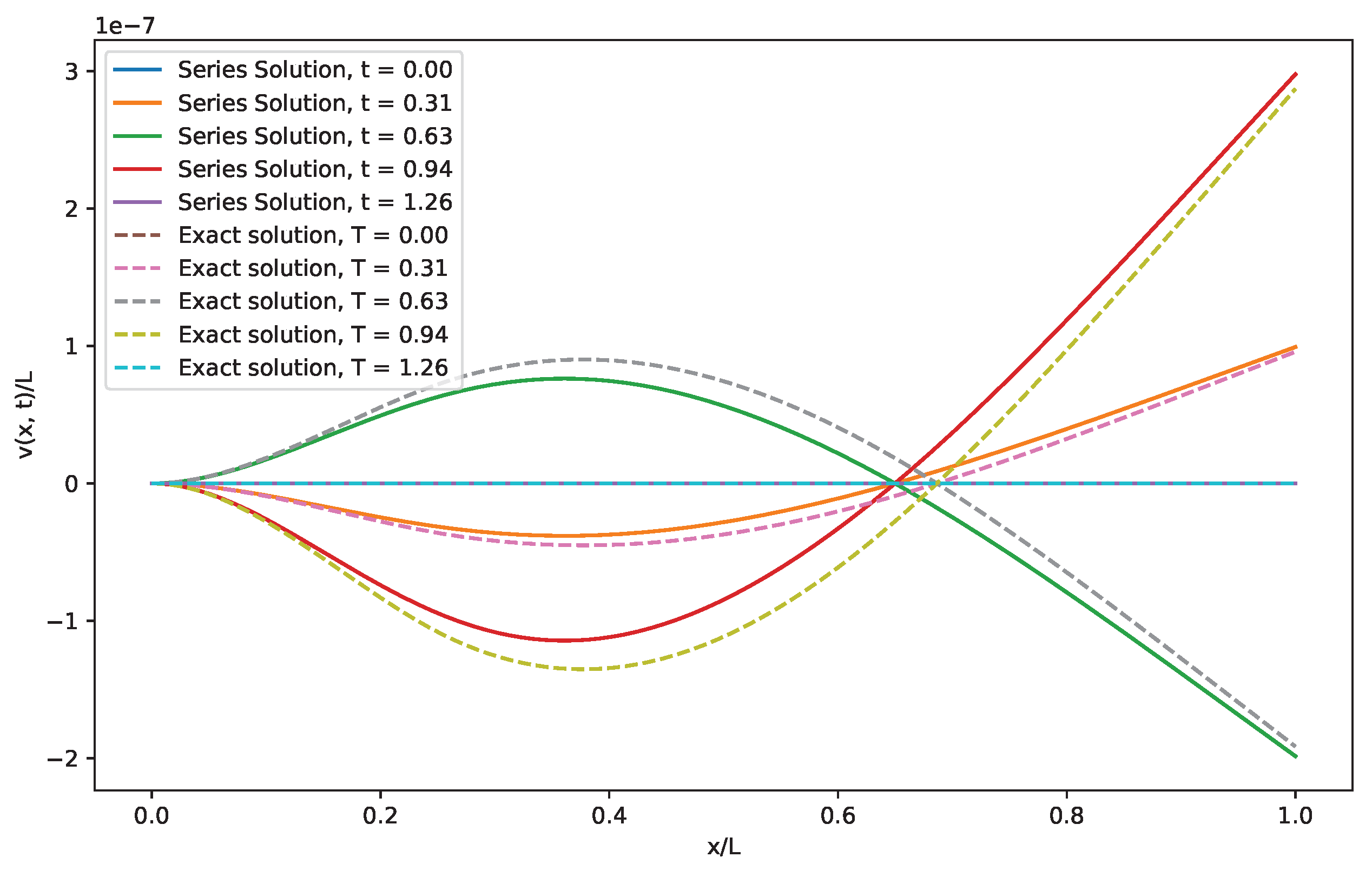
The results of the comparison between the series and closed form solution are detailed below. The properties of the tube and fluid are shown in
Table 1. As we can see in
Figure 2, a very good agreement is found for an empty tube, while the effect of the fluid can be observed in
Figure 3 in terms of the tube’s transient deflection.
5. Conclusion
Considering a general equation of motion for a tube carrying fluid subjected to harmonic excitation, an analytical technique based on Green’s function method has been developed to find a solution for a tube carrying fluid. The derived exact solution is more accurate than the conventional series expansion or Galerkin’s method, and it does not require knowledge of the free vibration problem’s eigenfunctions or eigenvalues. The proposed method might also be extended to include moment solicitation and other configurations, such as multi-span tubes, different boundary conditions, and structural vibrations.
References
- Paidoussis, M.P. Fluid-Structure Interactions: Slender Structures and Axial Flow, 2nd edition ed.; Academic Press: Amsterdam; Boston MA, 2014.
- Tembely, M.; Lecot, C.; Soucemarianadin, A. Prediction and evolution of drop-size distribution for a new ultrasonic atomizer. Applied Thermal Engineering 2011, 31, 656–667. [CrossRef]
- Lin, Y.H.; Chu, C.L. Active Flutter Control Of A Cantilever Tube Conveying Fluid Using Piezoelectric Actuators. Journal of Sound and Vibration 1996, 196, 97–105. [CrossRef]
- Housner, G.W. Bending Vibrations of a Pipe Line Containing Flowing Fluid. Journal of Applied Mechanics 2021, 19, 205–208. [CrossRef]
- Weaver, D.S.; Unny, T.E. On the Dynamic Stability of Fluid-Conveying Pipes. Journal of Applied Mechanics 1973, 40, 48–52. [CrossRef]
- Païdoussis, M.P.; Semler, C.; Wadham-Gagnon, M.; Saaid, S. Dynamics of cantilevered pipes conveying fluid. Part 2: Dynamics of the system with intermediate spring support. Journal of Fluids and Structures 2007, 23, 569–587. [CrossRef]
- Ammari, K.; Tucsnak, M. Stabilization of Bernoulli–Euler Beams by Means of a Pointwise Feedback Force. SIAM Journal on Control and Optimization 2000, 39, 1160–1181. [CrossRef]
|
Disclaimer/Publisher’s Note: The statements, opinions and data contained in all publications are solely those of the individual author(s) and contributor(s) and not of MDPI and/or the editor(s). MDPI and/or the editor(s) disclaim responsibility for any injury to people or property resulting from any ideas, methods, instructions or products referred to in the content. |
© 2024 by the authors. Licensee MDPI, Basel, Switzerland. This article is an open access article distributed under the terms and conditions of the Creative Commons Attribution (CC BY) license (http://creativecommons.org/licenses/by/4.0/).


