1. Introduction
Granules and pellets play important roles as standalone dosage forms and dosage forms of further processing. Ensuring optimal pharmaceutical-physical properties is necessary in developing a dosage form. The flow property of multiparticulates is cardinal due to the accurate dosing or further processing. Insufficient flow characteristics of pellets and granules may cause difficulties in additional procedures.
Flow properties are determined by several factors derived from the nature of particles, such as shape, size, size distribution, surface, purity, crystallinity, interparticle forces: friction forces, surface tension, molecular forces [1,x1], and external factors such as the force of gravity, temperature, moisture content, electrostatic charge, aeration, particle-wall interaction [
2,
3,
4,
5] Examining the effect of these factors on powder flowability is still preferred topic since development in measurement techniques and powder flow theory is continuous.
Flow properties of particles could be characterized in a number of ways, applying basic methods: examining static angle of repose, flow through an orifice, compressibility measurements, shearing tests, observing avalanche behavior, and applying powder rheometers [
6,
7,
8].
Several empirical assessments were made regarding the effect of the properties of particles on powder flow using these methods.
Particles below 50μm practically have no flow due to van der Waals forces. An increase in particle size usually increases flowability. The flow rate achieves maximum at an orifice diameter-particle diameter ratio of 20-30 and stops completely below 6 and above the size 1200μm (Pharmaceutical Manufacturing Handbook: Production and Processes, Shayne Cox Gad, Ph.D., D.A.B.T., Wiley-Interscience, 2008)
Moisture content can affect flow properties too due to forces usually induced by surface tension. Low moisture content can lead to the development of electrostatic charges and inhibits flow [
9].
Several numeric models were created describing this flow through an orifice. These models are often based on the Brown-Richards equation:
Where Q is the flow rate, ρt is the powder density, DA is the circular aperture diameter, K and n are material-dependent constant and g is the force of gravity [
9].
Application of novel techniques of shape characterization of particles revealed correlation between flow properties and surface morphology. Benoît Mandelbrot’s theory of fractal geometry lead to the first alternative explanation of influence of shape factors on flow properties [
10]. Irregularity of shape usually causes poor flowability characteristics. Spherical and smooth particles have sufficient flow [
11].
Complexity of theory of powder flow derives from novel approach of particles behaving as self organized structures affecting each other. This principle dates back to 1987 when Per Bak, Chao Tang and Kurt Wiesenfeld created their top cited publication on self-organized criticality [
12] This theory perfectly fits Mandelbrot’s fractals which could describe several phenomena occurring in the nature. Bak et al took an example of a sandpile with an angle-of-repose θ. Addition of a small amount of sand results slight response but continuing sand addition the pile reaches a state when the local slope of the sand particles is higher than θ, avalanche effect takes place thus aiming a stable state.
Important step of the powder flow theory was the combination of fractal geometry with self-organized criticality which resulted the rotating drum technique [
13]. This was a relevant milestone in dynamic measurements and examination of the avalanche behavior in details [
14,
15,
16].
2. Results and Discussion
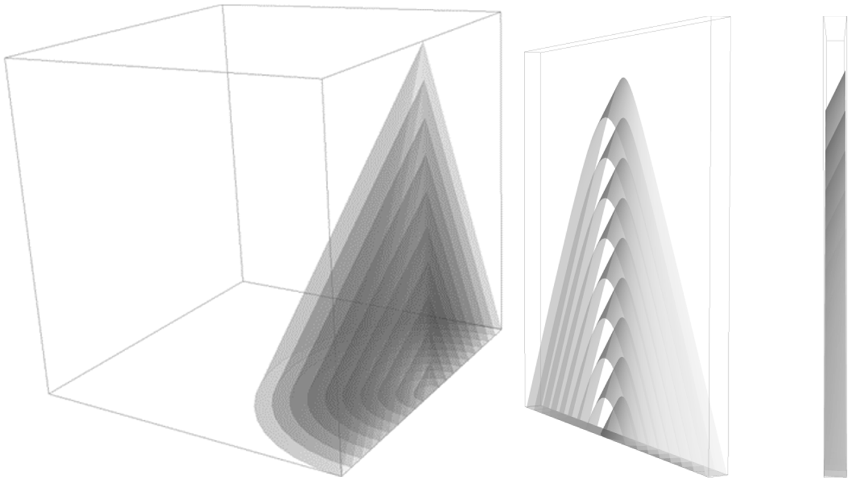
Flow curve is based on capturing real-time image data of projected conic section, which changes rapidly due to particles’ movement. Principle of this method contains the simplicity of a basic cone-growth model and the complexity of the self organized criticality. Cone growth could be characterized with the growth of the volume of the cone filled with particles. Measured flow curve is proportional to the changing height of the cone, so finding the relationship between the growing height and the volume of the cone shaped particles pile helps to understand the theoretical background of the non-linear fitting.
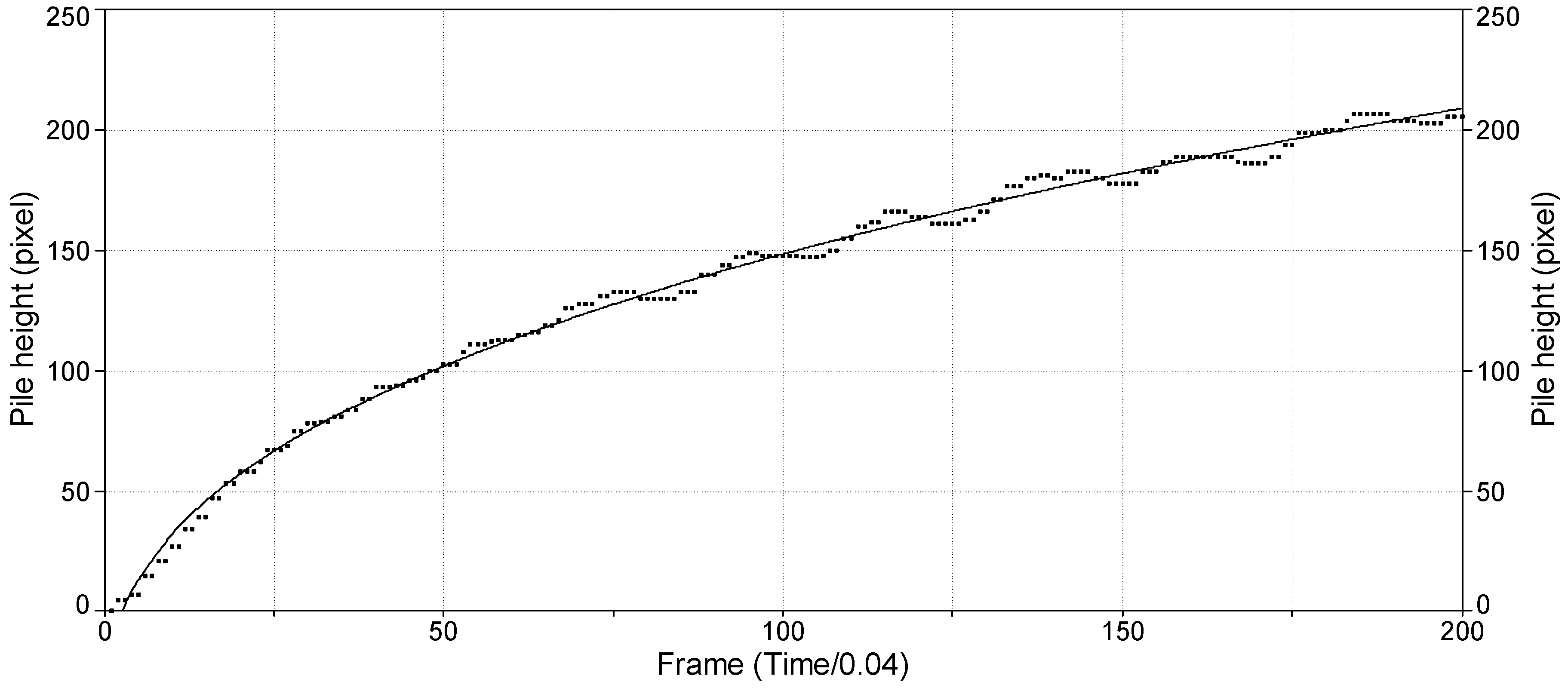
Figure 1 represents a flow curve measured by our method and the non-linear fitting with power law function, equation (2).
Where ‘y’ is the measured area, ‘t’ is the time, ‘a’ and ‘b’ are constants, ‘c’ is scaling exponent.
Volume (V) of a circular conic solid with radius ‘r’ and height ‘h’ can be described with the formula (3):
Assuming the static angle of repose to be nearly constant, radius ‘r’ can be expressed as (4):
where ‘h’ is the height of the cone, α is the static angle of repose.
Substituting ‘r’ in formula (3) volume of the cone becomes (5):
Measured curve proportional to the height of the cone can be expressed as (6):
Rearranging the formula the outline of a power law function can be discovered in expression (7):
Comparing formulas (2) and (7) and assuming, that the calculated ‘y’ value and the measured ‘h’ height as well as growing ‘V’ volume of the cone and ‘t’ time are in linear relationship respectively (y∝h,t∝V), we can hypothesise (8):
Value ‘a’ refers to the intercept which is constant according to the equation (2), but we also could hypothesise that it substitutes an asymptotic notation ‘o(x)k’ or deviation term ‘ε’. It can also represent the avalanche behaviour of the pile.
Value ‘b’ is proportional to the static angle of repose and the height of the pile, however if the observation is limited to a definite interval of time, the relationship for value ‘b’ described above (8) is not necessarily valid, moreover it is often in negative relationship with the static angle of repose. This phenomenon could be explained with the “flow through an orifice” method used in the experiments, since flowability of particles determines the flow rate through the orifice. Same weight of particles with good flowability produce lower piles than particles with poor flowability, conversely particles with good flowability produce higher piles than particles with poor flowability within a definite interval of time. In practice value ‘b’ refers to the height of the pile.
Value ‘c’ is originated from the formula of the volume of the cone. The higher the value ‘c’ is, the more cylindrical the pile becomes. In practice value ‘c’ refers to the growth rate of the pile.
Evaluation of the flow curve (
Figure 1) was very complex, since number of parameters could be obtained, such as pile growth rate, avalanche behaviour (count, amplitude, frequency) and using different functions fitting the curve, several other parameters were able to characterize the flow property.
2.1. Static angle of repose (SAOR) and flow time (FT)
Control measurements were carried out using classic method of static angle of repose measurement and observing flow time.
Table 1 represents the results.
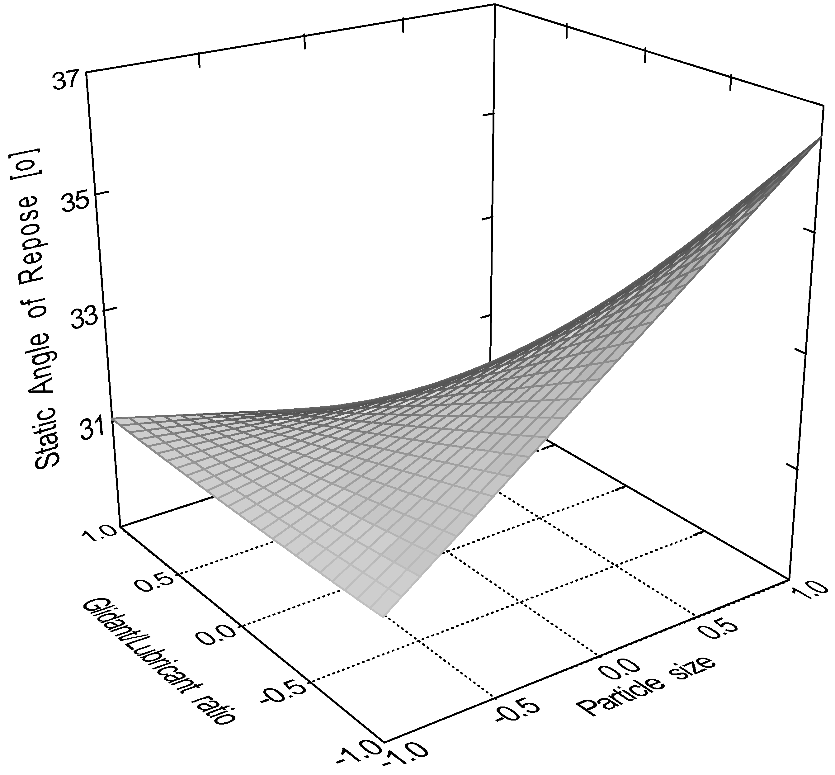
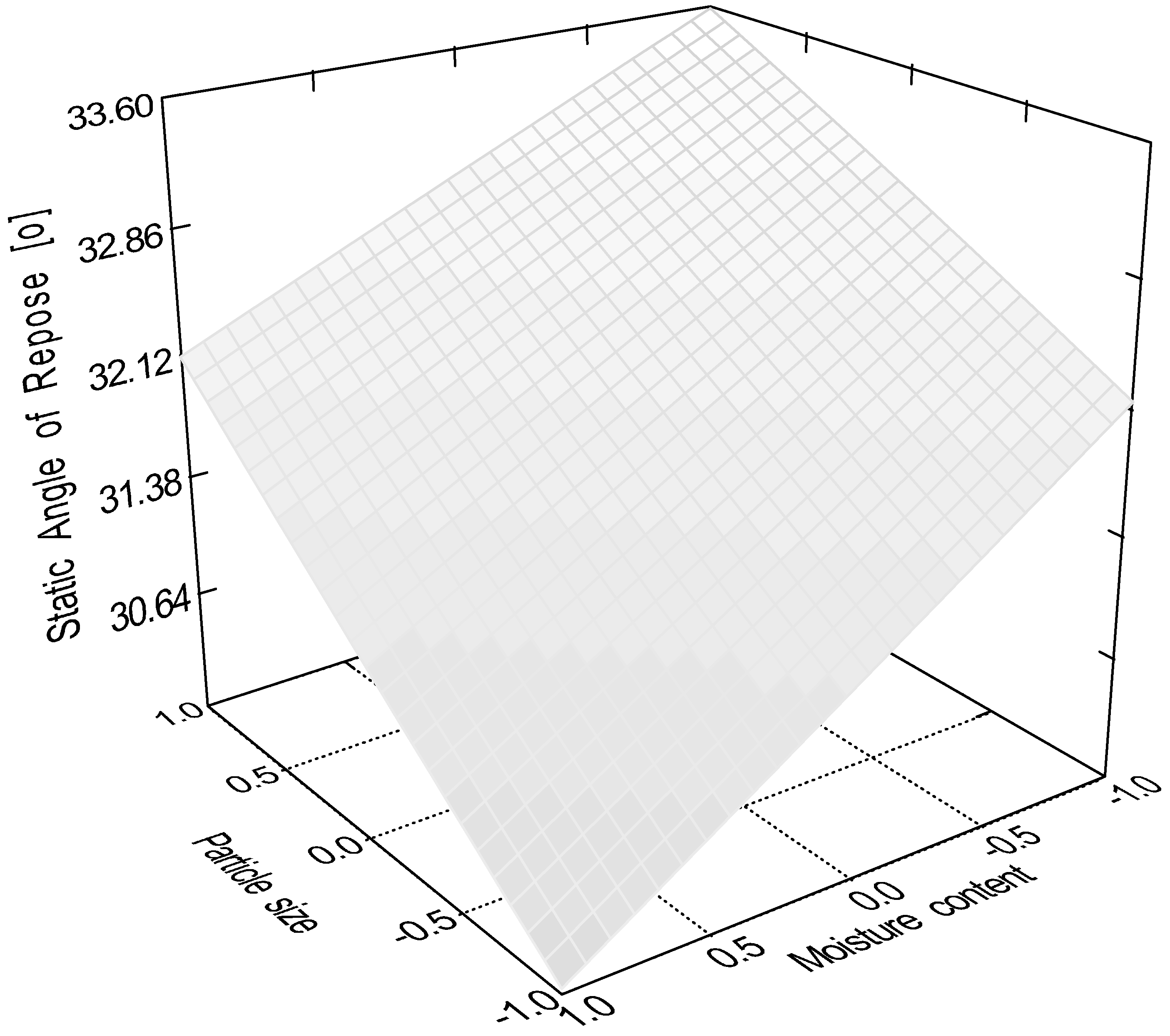
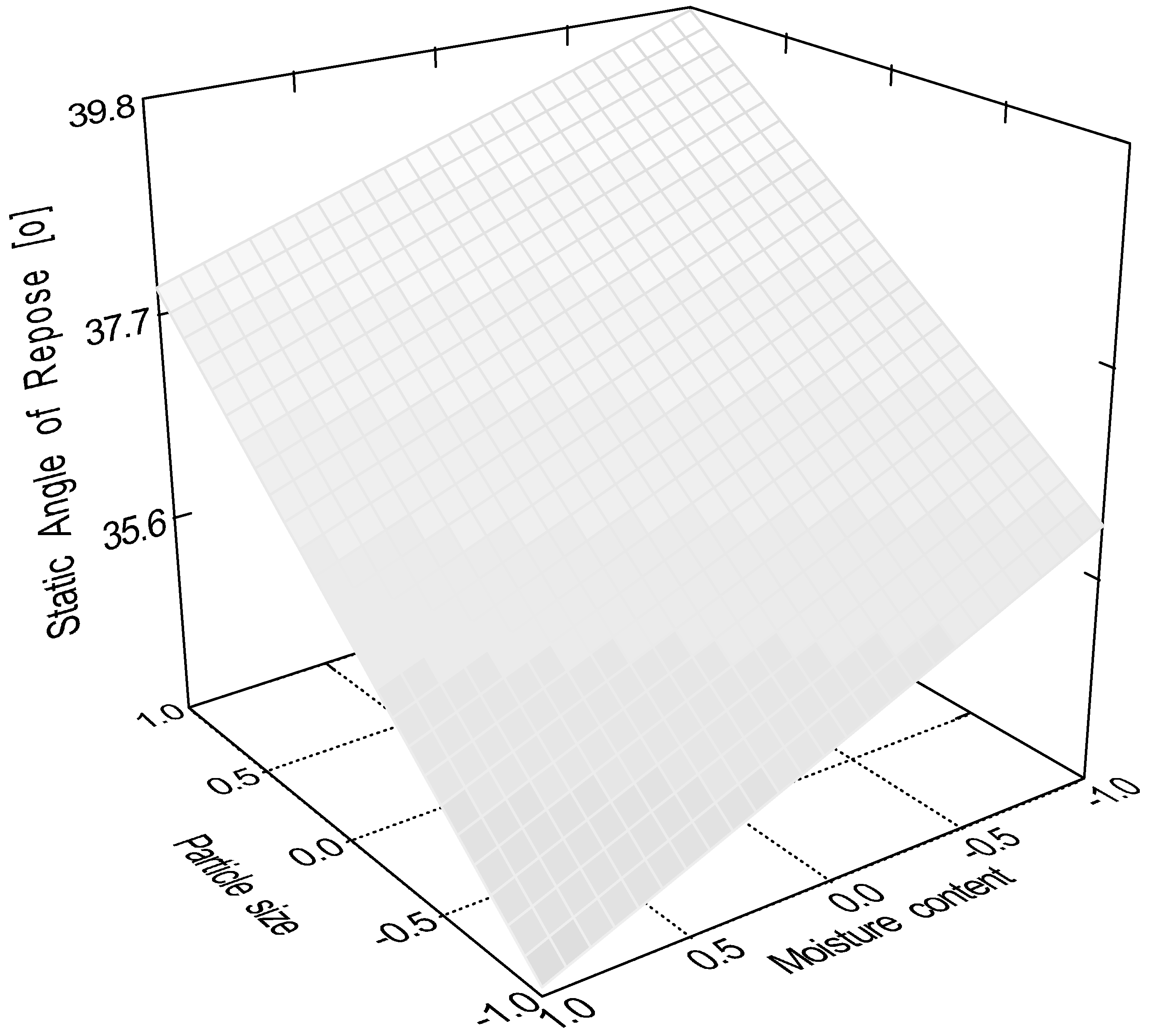
According to the evaluation of central composite design linear 2 factor interaction model is significant (p < 0.0001) for the data of static angle of repose. In this measurement factor x4 (sphericity, p < 0.0001), factor x1 (particle size, p = 0.0082), factor x2 (moisture content, p = 0.0485), interactions ‘x1x3’ (p = 0.0151) and ‘x3x4’ (p = 0.0161) were significant, where ‘x3’ is the glidant/lubricant ratio.
Figure 2,
Figure 3,
Figure 4 and
Figure 5 represent response surfaces of the static angle of repose measurement. Equation (9) is the mathematical formula of the response surface.
Quadratic model (equation10) was significant (p < 0.0001) for the flow time of the samples. Factors x
1 (particle size, p = 0.0001), x
3 (glidant/lubricant ratio, p = 0.0445), x
4 (sphericity, p < 0.0001), x
3x
4 (p = 0.0016) and x
12 (p < 0.0001) were significant.
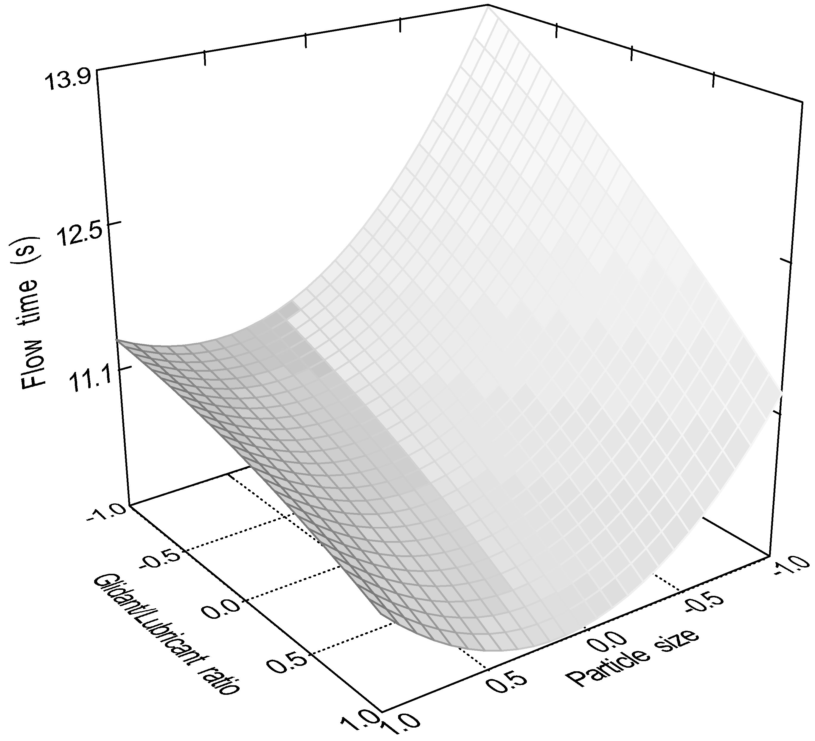
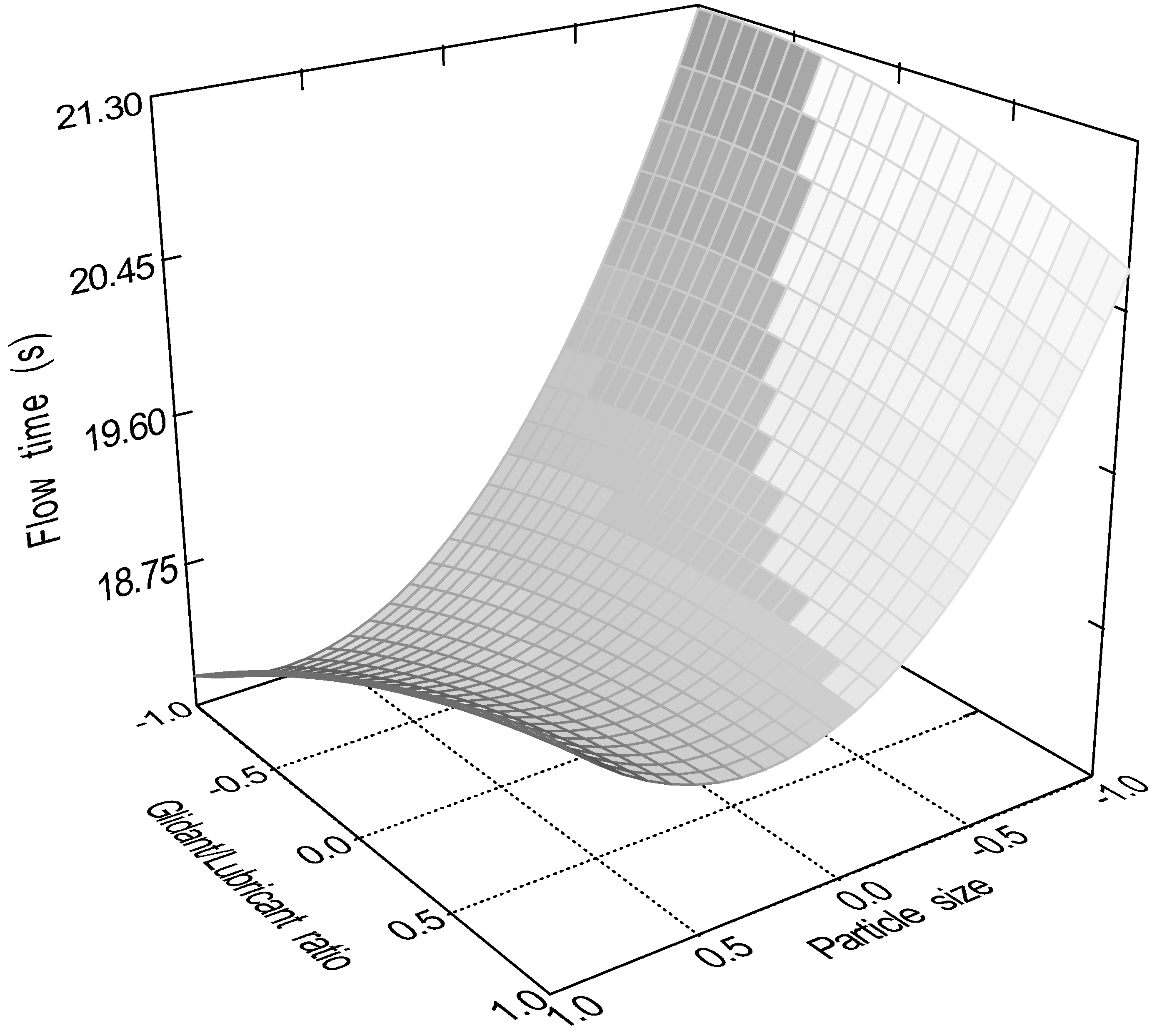
Figure 6,
Figure 7,
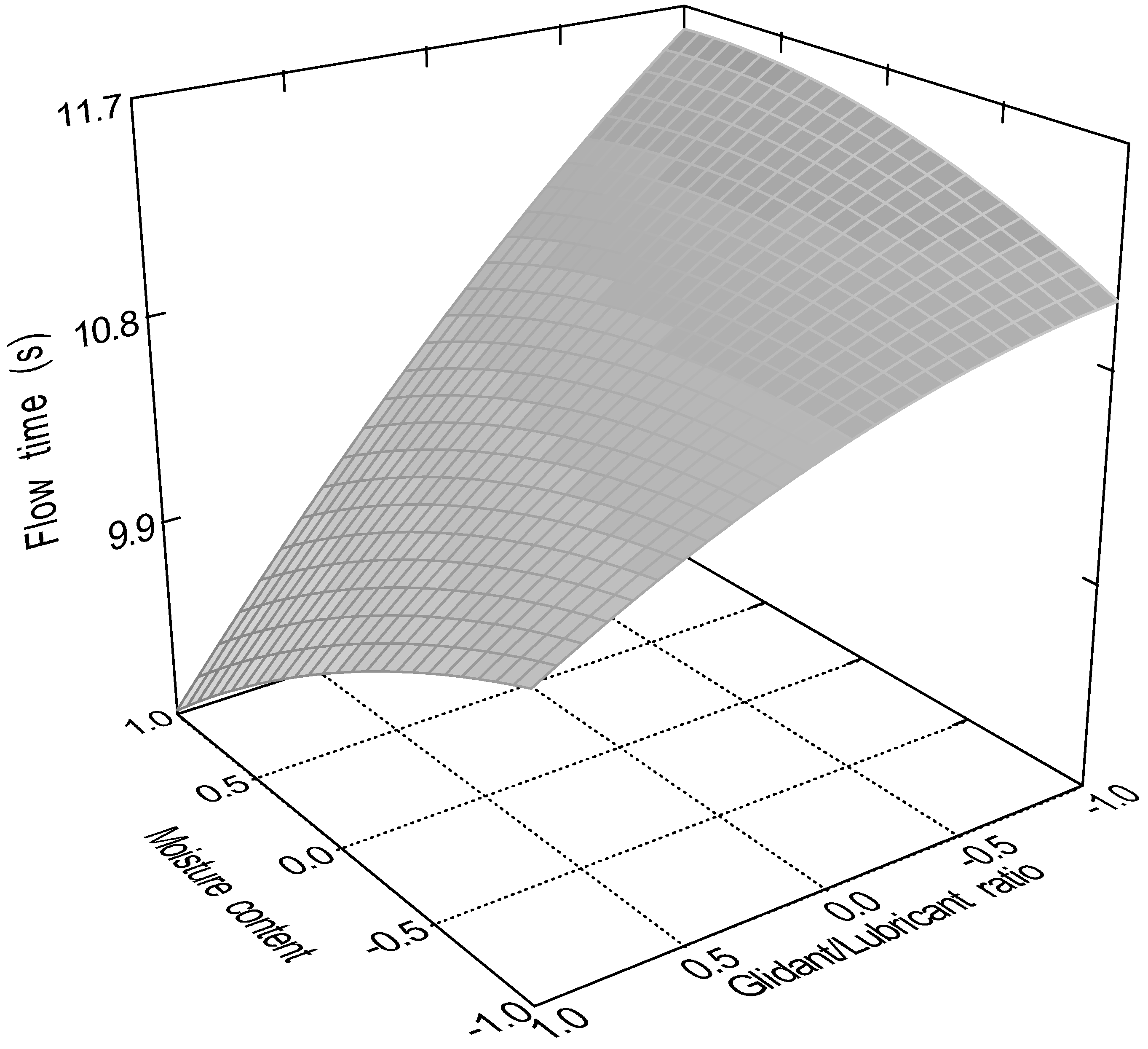
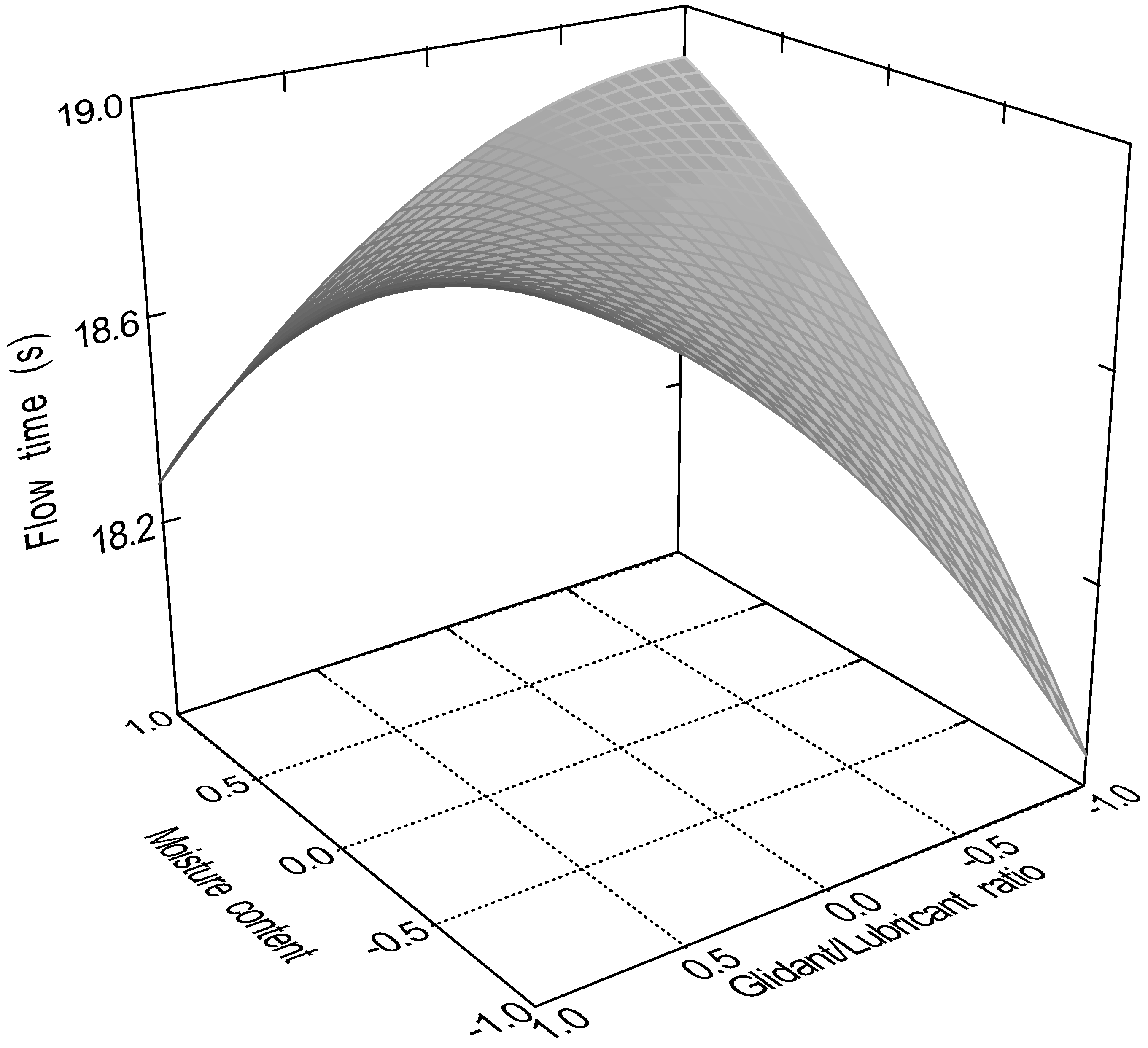
Figure 8 and
Figure 9 represent response surfaces of the model.
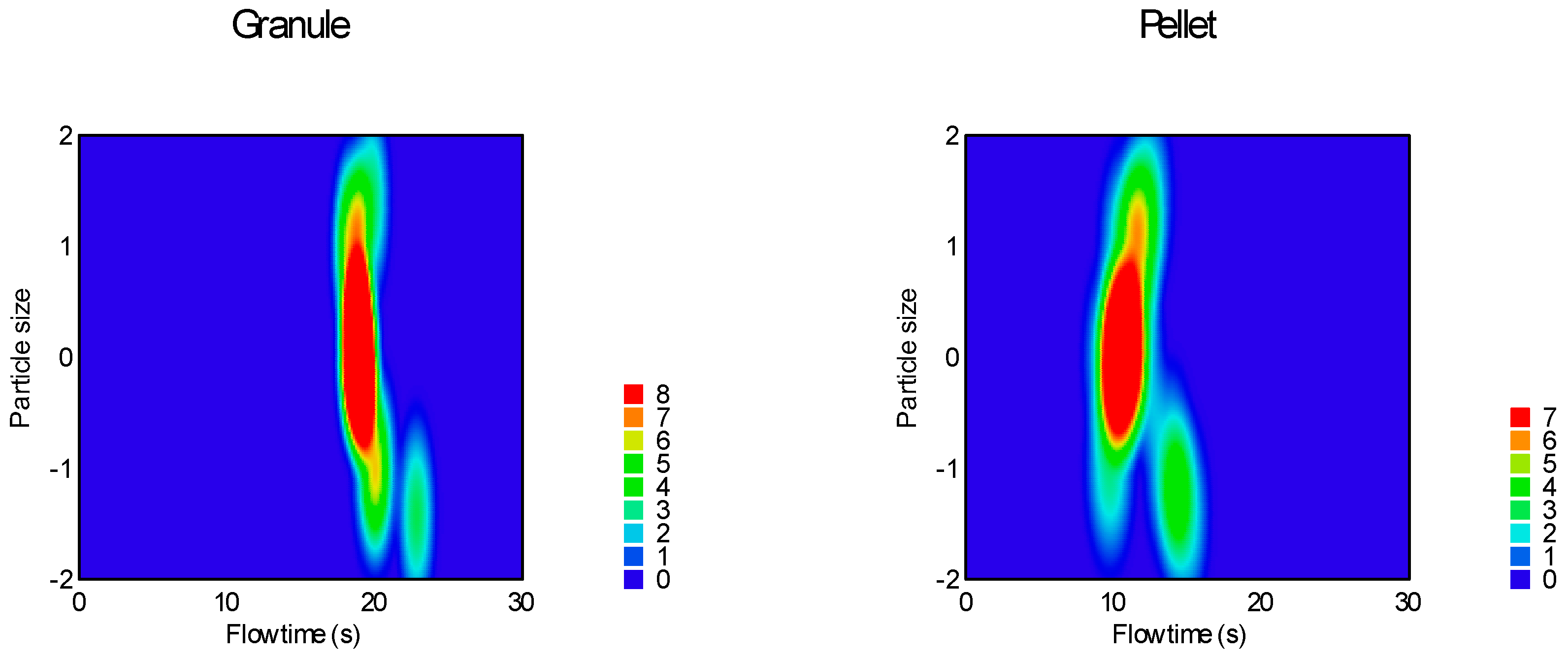
Sphericity and particle size were the most significant factors affecting both measured parameters, moisture content affected only the static angle of repose and glidant/lubricant ratio affected only the flow time.
Figure 10 clearly demonstrates the difference between granules and pellets on sample flow time.
2.2. Avalanche behaviour
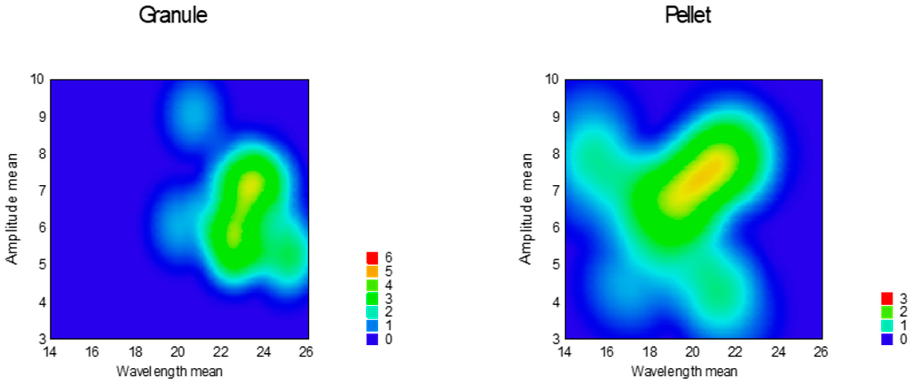
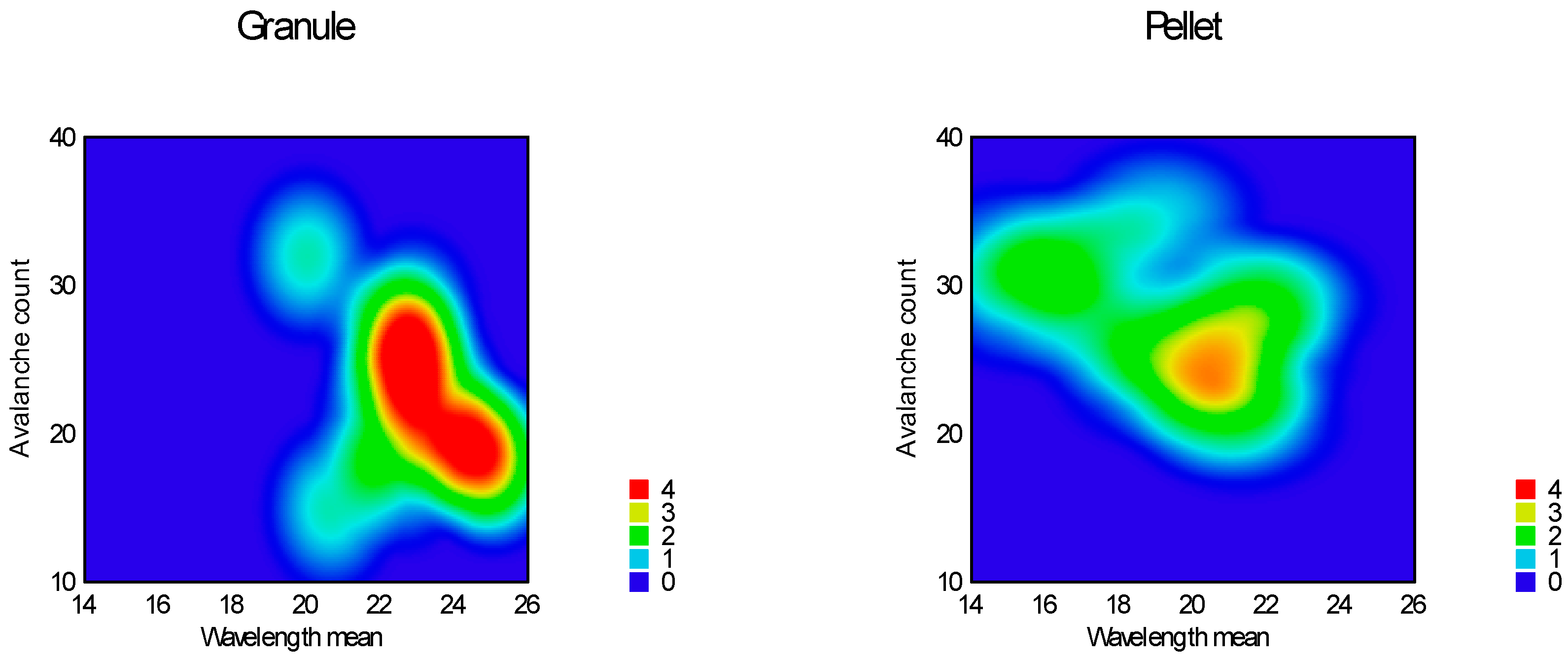
Avalanche behaviour was examined by evaluating the flow curve counting number of avalanches and determining their amplitude. Results are summarized in
Table 3, heat map of the model is presented on
Figure 11 and
Figure 12.
According to the response surfaces none of the factors affect the amplitude of the avalanches significantly, on the other hand wavelength mean and avalanche count could be used to characterize flow pattern. Reduced response surface linear model was adequate for the wavelength (equation 11, p = 0.0002) and count of avalanches (equation 12, p = 0.0066). In both cases only factor x4 (sphericity) was significant (p < 0.0001).
According to equations above avalanche wavelength was longer at granules and shorter at pellets, avalanche count was rare at granules and frequent at pellets.
2.3. Non-linear fitting of flow curve
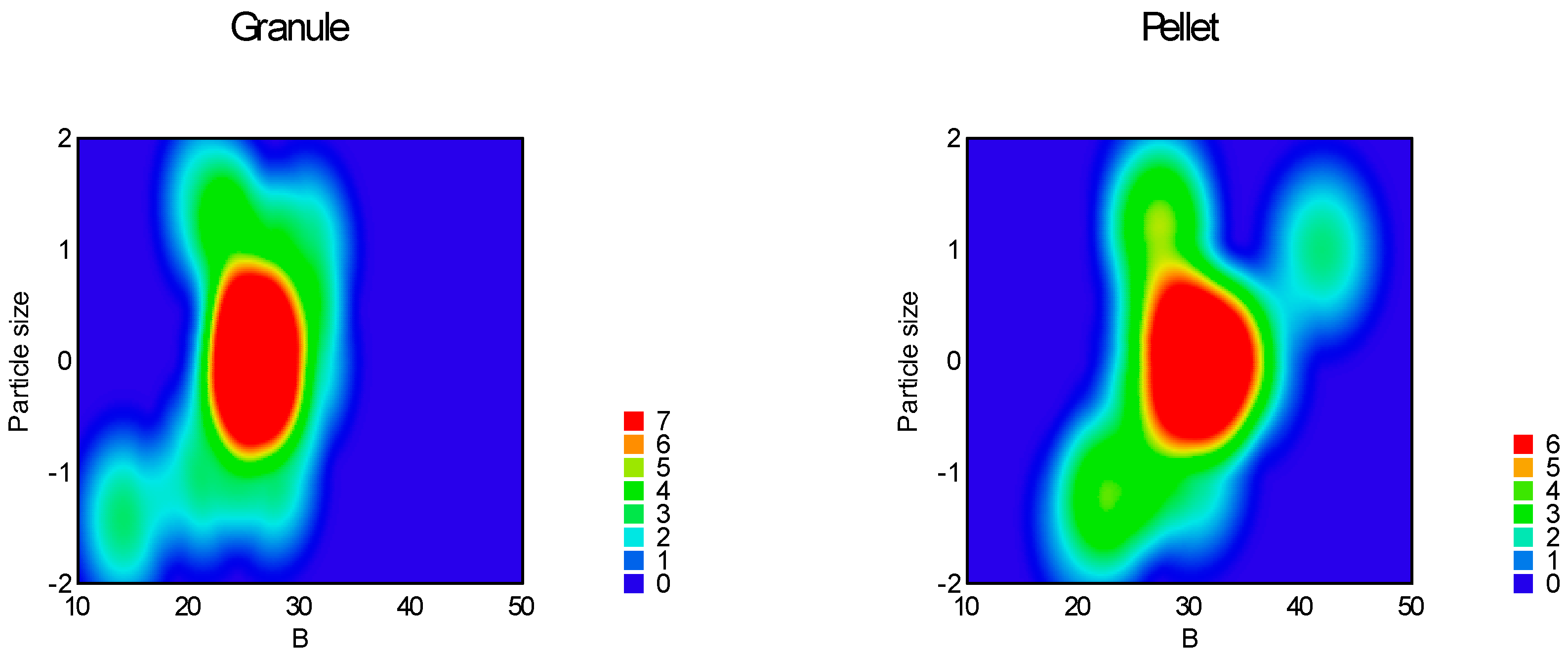
Table 5 contains the correlation of all examined parameters including parameters of empirical methods. ANOVA analysis of Predicted R-Squared was negative for parameter ‘a’, which means, overall mean of ‘a’ is a better predictor for the model. Reduced quadratic response surface model was adequate for parameter ‘b’ (equation 13, p < 0.0001), in which factors x1 (particle size, p = 0.0002) and factor x4 (sphericity, p < 0.0001), interaction x3x4 (p = 0.0025) and squared factors x12 (0.0001) and x22 (p = 0.0394) were significant.
Reduced quadratic model was adequate for parameter ‘c’ (equation 14, p = 0.0001), where factor x1 (particle size, p = 0.0092), factor x4 (sphericity, p < 0.0001), interaction x3x4 (p = 0.0108) and x12 (p = 0.0007) were significant.
Adequate model (equation 15) for parameter ‘a+b’ was found to be linear with p = 0.0001. In this case factor x2 (moisture content, p = 0.03) and factor x4 (sphericity, p < 0.0001) were significant.
Reduced quadratic model (equation 16) seemed to be adequate for the area under the flow curve (p < 0.0001). Factor x1 (particle size, p = 0.0003), factor x4 (sphericity, p < 0.0001) and squared factor x12 were significant in this case.
According to the adequate models at time-limited measurements parameter ‘b’, which is originated from the angle of repose and the height of the pile increases as the particle size increases. It reaches a maximum at around 900 μm particle size, then it slightly decreases. At granules parameter ‘b’ decreases, at pellets increases.
Parameter ‘c’, which is originated from the volume of the theoretical cone of the pile is in close negative correlation with parameter ‘b’.
Parameter ‘a+b’, which is probably combination of the avalanche behaviour and the angle of repose/avalanche is the only parameter of the non-linear fitting affected significantly by the moisture content. As the moisture increases, ‘a+b’ increases. The increasing sphericity increases its value as well.
Parameter ‘AUFC’ is in close negative correlation with the flow time. After increase it reaches a maximum value at 900 μm, then it decreases as the particle size increases. Granules decreases, pellets increase its value.
3. Materials and Methods
Pellets and granules of different sizes were produced containing 10% ibuprofen (Hungaropharma, Budapest, Hungary), 37% α-lactose-monohydrate (DC, BDI, Zwolle, The Netherlands), 50% microcrystalline cellulose (Avicel PH 101, FMC, Philadelphia, USA), and 3% ethylcellulose (Hercules, Wilmington, USA). Purified water was used as granulation liquid. Quality of all materials used in the experiments was Ph. Eur.
3.1. Production of samples
Samples were produced according to a central composite experimental design with three numeric (particle size, moisture content, glidant/lubricant content) and one categoric factor (granule/pellet) (
Table 6).
Pellets were produced using a 1000 ml laboratory high-shear mixer (Pro-C-epT 4M8 Granulator, Belgium, Zelzate) with a three blade impeller and a chopper. Granules were produced using an oscillatory granulator (Erweka GmbH, Heusenstamm, Germany). Samples of both productions were air dried at 40°C for 1 hour. Granules then passed through the oscillatory granulator again according to the desired particle size. Purified water was used as granulation liquid in both cases. Each batch had a total dry mass of 120 g.
After preparation samples were stored in closed containers over a period of 24 h at 25°C.
Appropriate fraction of produced samples was selected by sieving according to the particle size determined by the experimental design. Moisture content was adjusted after moisture analysis based upon weight loss on drying (Mettler LP16, Mettler Toledo). Addition of proper amount of purified water was carried out in a fluid equipment Mini-Glatt 4 (Glatt GmbH, Binzen, Germany) applying top spray method then moisture and particle size analysis was performed again.
Glidant/lubricant mixture was finally added applying 5 minutes blending in a KB cube mixer (Erweka GmbH, Langen, Germany) at 25 rpm.
Glidant used in our experiments was talc which is a commonly used glidant, lubricant was magnesium stearate which was also described to have glidant properties. Amount of both glidant and lubricant was constant 5% of the total mass and was used in different ratios according to
Table 7. Each examined sample had total mass of 100 g.
3.2. Experimental setup for powder flow measurements
Merging the theory of the static and dynamic angle of repose measurement new equipment was created based. Main body of the equipment was regular acid-resistant stainless steel funnel described in Ph.Eur. 6 / 2.9.16., measuring 100±0.01 mm top diameter, 100±0.01 mm length and outflow opening of 10±0.01 mm cut perpendicular to the axis of symmetry. The funnel was mounted above a plexiglass plane. The distance between the plexiglass and the nozzle was 60 mm.
A regular CMOS camera (Logitech QuickCam V-UAP9, 25 frames per second, 128 x 160 pixel resolution) was applied as the detector compartment placed 200mm from the base point of the nozzle so its optical axis was on the plane of the plexiglass towards the nozzle. The whole device was placed in front of a black pane using forward illumination in order to enhance the image analysis.
4.3. Image analysis and evaluation
The measurement was done by loading the funnel with 100 g of the sample and recording the contour of particle flow using the digital CMOS camera. Forming of particle pile in 3D was thus converted to 2D. In order to retrieve suitable data for quantitative analysis, three preliminary steps were taken.
The first step was the extraction of all captured frames from the recorded material. Second step was the slicing of the frames vertically into 32 equal pieces.
Choosing the right slice for the analysis was a crucial point. Middle slices of the captured frames were technically unfeasible, since the bulk flow took place there. Terminal slices were unsuitable as well, because there is no event in the first seconds there. Thus only one slice was chosen as close to the middle of the frame as possible so that the bulk flow did not disturb the analysis (
Figure 19).
The third step was the digital image enhancement and measurement using Zeiss AxioVision software. The image analysis of the slices consisted of the allocation of bright space (representing the particles) and dark space in the image (representing the black background). Measured areas of bright spaces of single slices were used for the statistical evaluation to characterize the particle flow.
Software TableCurve® 2D v5.01 (Systat Software Inc., London, UK) was used to evaluate the data set. A graph was created plotting the measured areas in the function of time, which resulted in a particle flow curve. Avalanche behavior could be observed, forming sine wave-like patterns. Several curve characteristics were measured, such as wavelength, amplitude, and count of avalanches, which were both averaged and observed in function of time. Non-linear fitting was performed using TableCurve®’s power law function (2.)
Flow time was measured from the recorded material, and static angle-of-repose was directly calculated from the last frame, averaging the angles on both sides of the pile.
4. Conclusions
The static angle of repose measurement combined with real-time image analysis offers new possibilities in powder flowability determination techniques. This method can detect avalanche behavior, static angle of repose, and flow time simultaneously. Creating a geometrical background of the cone-growth model for the measurements, the coefficients of non-linear fitting could be associated with definite geometrical parameters. By examining the effect of particle size, moisture content, glidant/lubricant ratio, and the role of pellets or granules (sphericity), it could be established that sphericity and particle size are the most significant factors affecting flowability measurements. However, the cone-growth model could also determine the effect of other less important factors. Parameters of avalanche behavior were significantly affected only by the sphericity; thus, in our experiments, self-organized criticality during the toppling of particles unfolded only a small part of hidden relations between examined factors and the flowability.
Supplementary Materials
Video: S1: Pellet - particle size 320 - 800 μm., S2: Granule - particle size 320 - 800 μm
Author Contributions
Conceptualization, Attila Dévay and Szilárd Pál; Data curation, Szilárd Pál; Formal analysis, Sándor Nagy; Funding acquisition, Szilárd Pál; Investigation, Sándor Nagy; Methodology, Gyula Farkas and Szilárd Pál; Project administration, Szilárd Pál; Resources, Szilárd Pál; Software, Gyula Farkas and Szilárd Pál; Supervision, Szilárd Pál; Validation, Gyula Farkas, Aleksandar Széchenyi and Szilárd Pál; Visualization, Gyula Farkas and Szilárd Pál; Writing – original draft, Gyula Farkas; Writing – review & editing, Aleksandar Széchenyi and Szilárd Pál.
Institutional Review Board Statement
Not applicable.
Informed Consent Statement
Not applicable.
Data Availability Statement
The data that support the findings of this study are available from the corresponding author Sz.P.
Conflicts of Interest
The authors declare no conflict of interest
References
- Stanley-Wood, N. Particle characterisation in bulk powders. In Characterisation of Bulk Solids, 1st ed.; Don McGlinchey, Ed.; Blackwell Publishing Ltd: Carlton, Australia, 2005; pp. 1–45. [Google Scholar]
- Freeman, R., The flowability of powders-an empirical approach International, Conference on Powder and Bulk Solids Handling, IMechE HQ, London, 2000.
- Hiestand, E.N. Powders: particle–particle interactions. J. Pharm. Sci. 1966, 35, 1325–1344. [Google Scholar] [CrossRef]
- Carstensen, J.T. Mechanical Properties and Rate Phenomena. In Solid Pharmaceutics; Academic Press: New York, 1980. [Google Scholar]
- Velasco, A.; Muñoz-Ruiz, A.J.; Perales, M.C.; Muñoz, N.; Jiménez-Castellanos, M.R. Evaluation of an adequate method of estimating flowability according to powder characteristics. Int. J. Pharm. 1994, 103, 155–161. [Google Scholar] [CrossRef]
- Carr, R.L., Jr. Classifying flow properties of solids. Chem. Eng. 1965, 7, 163–167. [Google Scholar]
- Kaye, B.H.; Gratton-Liimatainen, J.; Faddis, N. Studying the avalanching behaviour of a powder in a rotating disc. Part. Part. Syst. Charact. 1995, 12, 232–236. [Google Scholar] [CrossRef]
- Lee, Y.S.L.; Poynter, R.; Podczeck, F.; Newton, J.M. Development of a dual approach to assess powder flow from avalanching behavior. AAPS Pharm. Sci. Tech. 2000, 1, 21. [Google Scholar] [CrossRef]
- Stephen A. Howard, Solids: Flow Properties In: Encyclopedia of Pharmaceutical Technology: Volume 6 (3rd ed.). Swarbrick, J. Eds, Informa Healthcare USA, Inc. (2007). USA, ppCRC Press. [CrossRef]
- Hickey, A.J.; Concessio, N.M. Flow properties of selected pharmaceutical powders from a vibrating spatula. Part. Syst. Charact. 1994, 11, 457–462. [Google Scholar] [CrossRef]
- Danjo K, Kinoshita K, Kitagawa K, Iida K, Sunada H, Otsuka A. Effect of particle shape on the compaction and flow properties of powders. Chem Pharm Bull. 1989;37(11):3070–3073. [CrossRef]
- Per Bak, Chao Tang, and Kurt Wiesenfeld, Self-organized criticality: An explanation of the 1/f noise, Phys. Rev. Lett., 1987, 59, 381-384. [CrossRef] [PubMed]
- Kaye, B.H. Characterizing the flowability of powder using the concepts of fractal ge-ometry and chaos theory. Part. Part. Syst. Charact. 1997, 14, 53–6. [Google Scholar] [CrossRef]
- Han R., Feng J., Zhang Y., Yang H., Zivkovic V., Li R., Numerical simulation of avalanche propagation dynamics in a rotating drum, 2021, Powder Technol., 380, pp. 199 - 204. [CrossRef]
- McLaren C.P., Leistner B.J., Pinzello S., Cano-Pleite E., Müller C.R., Onset and dynamics of avalanches in a rotating cylinder: From experimental data to a geometric model, 2022, Physical Review E, 106 (5), art. no. 054902. [CrossRef]
- Orefice L., Remmelgas J., Neveu A., Francqui F.,. Khinast J.G.,A novel methodology for data analysis of dynamic angle of repose tests and powder flow classification, Powder Technol., 2024, Volume 435., 119425. [CrossRef]
Figure 1.
Flow curve of a sample and its non-linear fitting.
Figure 1.
Flow curve of a sample and its non-linear fitting.
Figure 2.
Effect of glidant/lubricant ratio and particle size of pellets on the static angle of repose measurement.
Figure 2.
Effect of glidant/lubricant ratio and particle size of pellets on the static angle of repose measurement.
Figure 3.
Effect of glidant/lubricant ratio and particle size of granules on the static angle of repose measurement.
Figure 3.
Effect of glidant/lubricant ratio and particle size of granules on the static angle of repose measurement.
Figure 4.
Effect of moisture content and particle size of pellets on the static angle of repose measurement.
Figure 4.
Effect of moisture content and particle size of pellets on the static angle of repose measurement.
Figure 5.
Effect of moisture content and particle size of granules on the static angle of repose measurement.
Figure 5.
Effect of moisture content and particle size of granules on the static angle of repose measurement.
Figure 6.
Effect of glidant/lubricant ratio and particle size of pellets on the flow time measurement.
Figure 6.
Effect of glidant/lubricant ratio and particle size of pellets on the flow time measurement.
Figure 7.
Effect of glidant/lubricant ratio and particle size of granules on the flow time measurement.
Figure 7.
Effect of glidant/lubricant ratio and particle size of granules on the flow time measurement.
Figure 8.
Effect of moisture content and particle size of pellets on the flow time measurement.
Figure 8.
Effect of moisture content and particle size of pellets on the flow time measurement.
Figure 9.
Effect of moisture content and particle size of granules on the flow time measurement.
Figure 9.
Effect of moisture content and particle size of granules on the flow time measurement.
Figure 10.
Heat map of effect of particle size and sphericity on flow time.
Figure 10.
Heat map of effect of particle size and sphericity on flow time.
Figure 11.
Heat map of effect of sphericity on avalanche amplitude and wavelength.
Figure 11.
Heat map of effect of sphericity on avalanche amplitude and wavelength.
Figure 12.
Heat map of effect of sphericity on avalanche count and wavelength.
Figure 12.
Heat map of effect of sphericity on avalanche count and wavelength.
Figure 13.
Heat map of effect of particle size and sphericity on parameter ‘b’.
Figure 13.
Heat map of effect of particle size and sphericity on parameter ‘b’.
Figure 14.
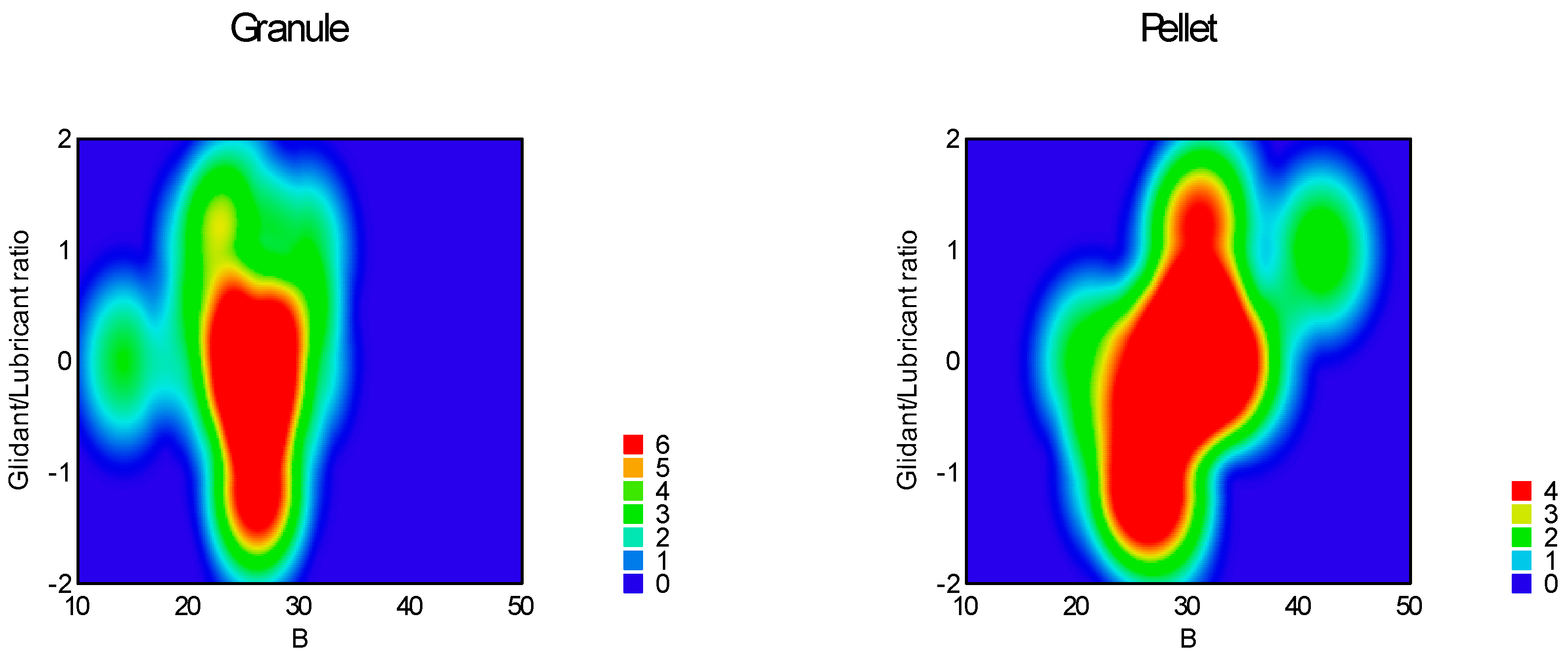
Heat map of effect of glidant/lubricant ratio and sphericity on parameter ‘b’.
Figure 14.
Heat map of effect of glidant/lubricant ratio and sphericity on parameter ‘b’.
Figure 15.
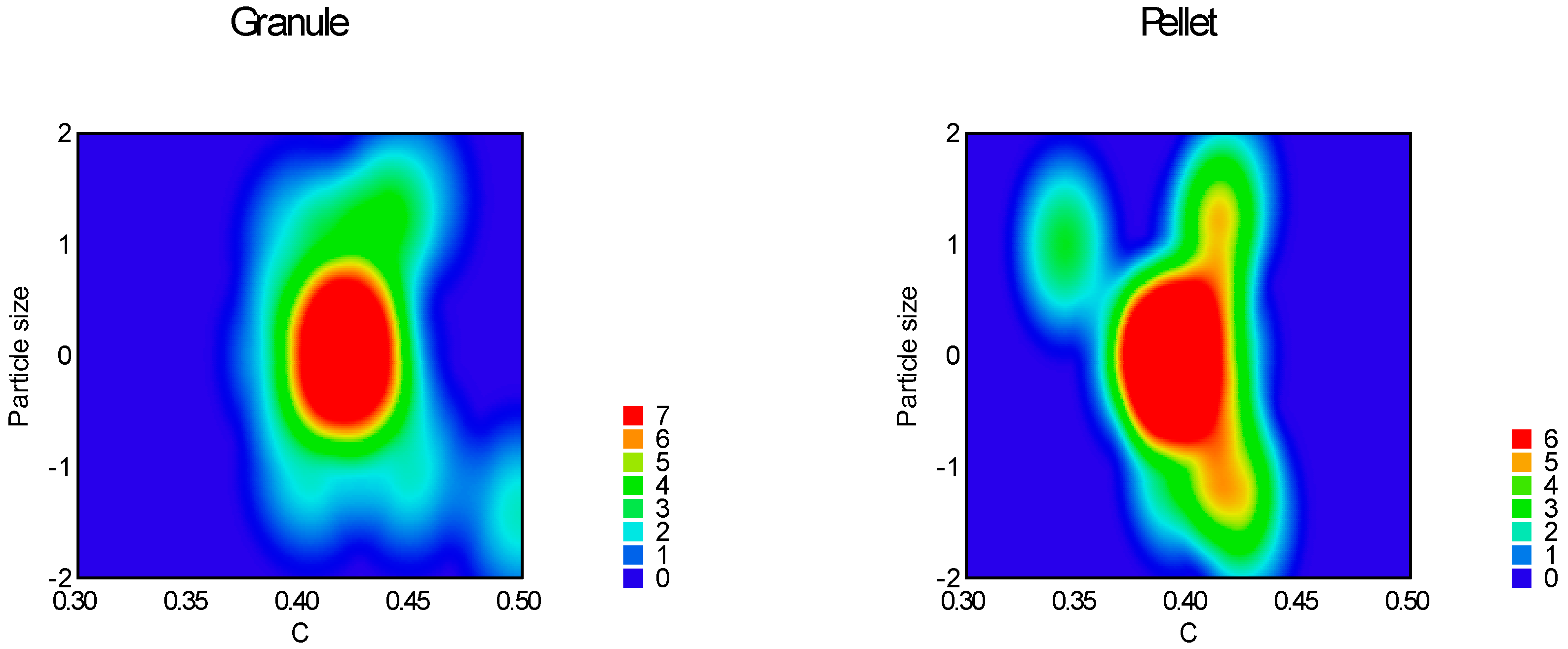
Heat map of effect of particle size and sphericity on parameter ‘c’.
Figure 15.
Heat map of effect of particle size and sphericity on parameter ‘c’.
Figure 16.
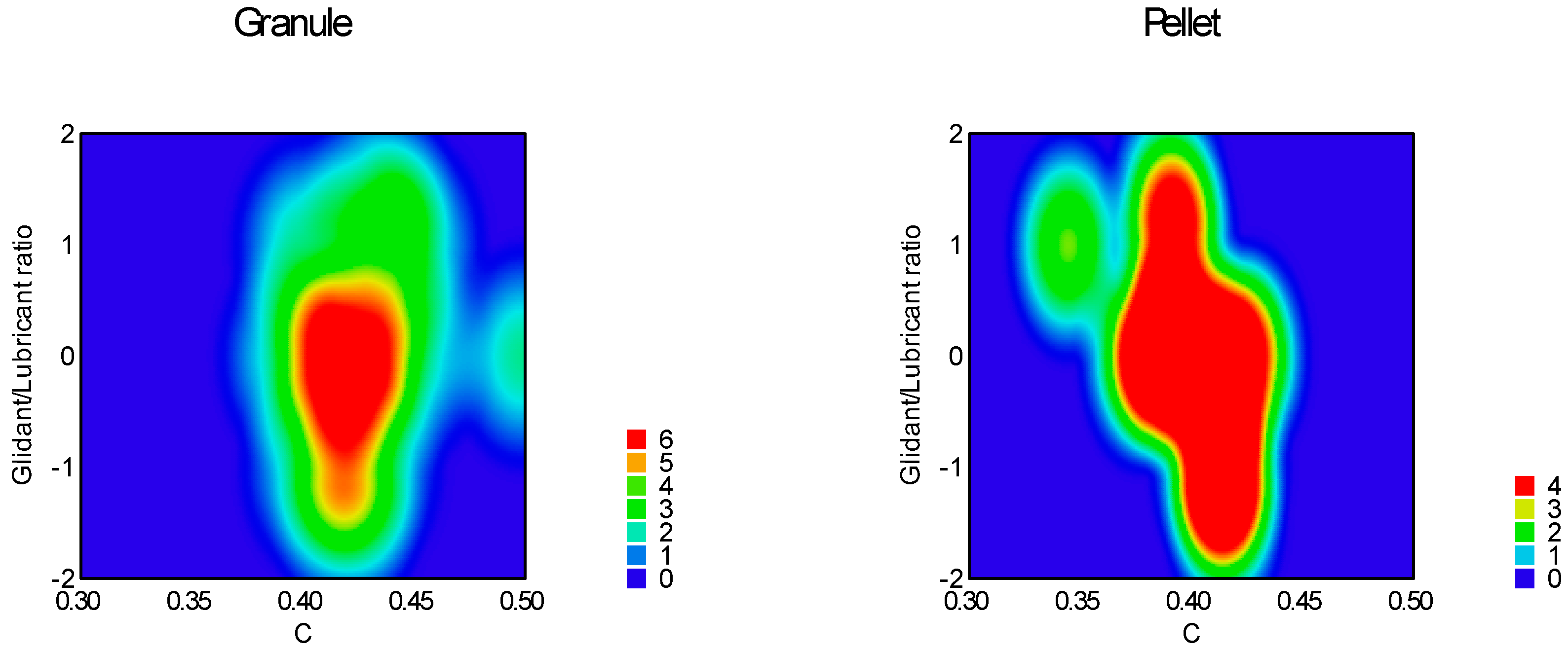
Heat map of effect of glidant/lubricant ratio and sphericity on parameter ‘c’.
Figure 16.
Heat map of effect of glidant/lubricant ratio and sphericity on parameter ‘c’.
Figure 17.
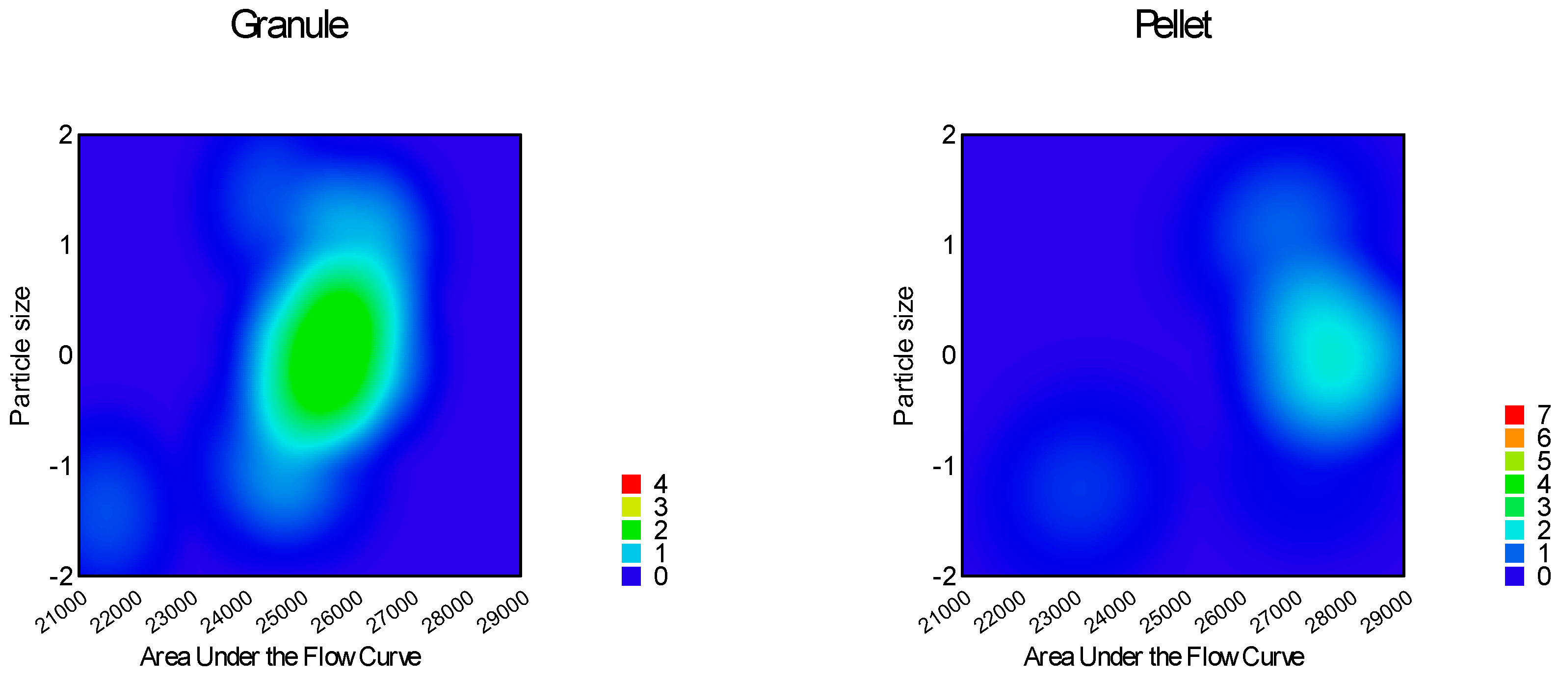
Heat map of effect of particle size and sphericity on parameter ‘AUFC’.
Figure 17.
Heat map of effect of particle size and sphericity on parameter ‘AUFC’.
Figure 18.
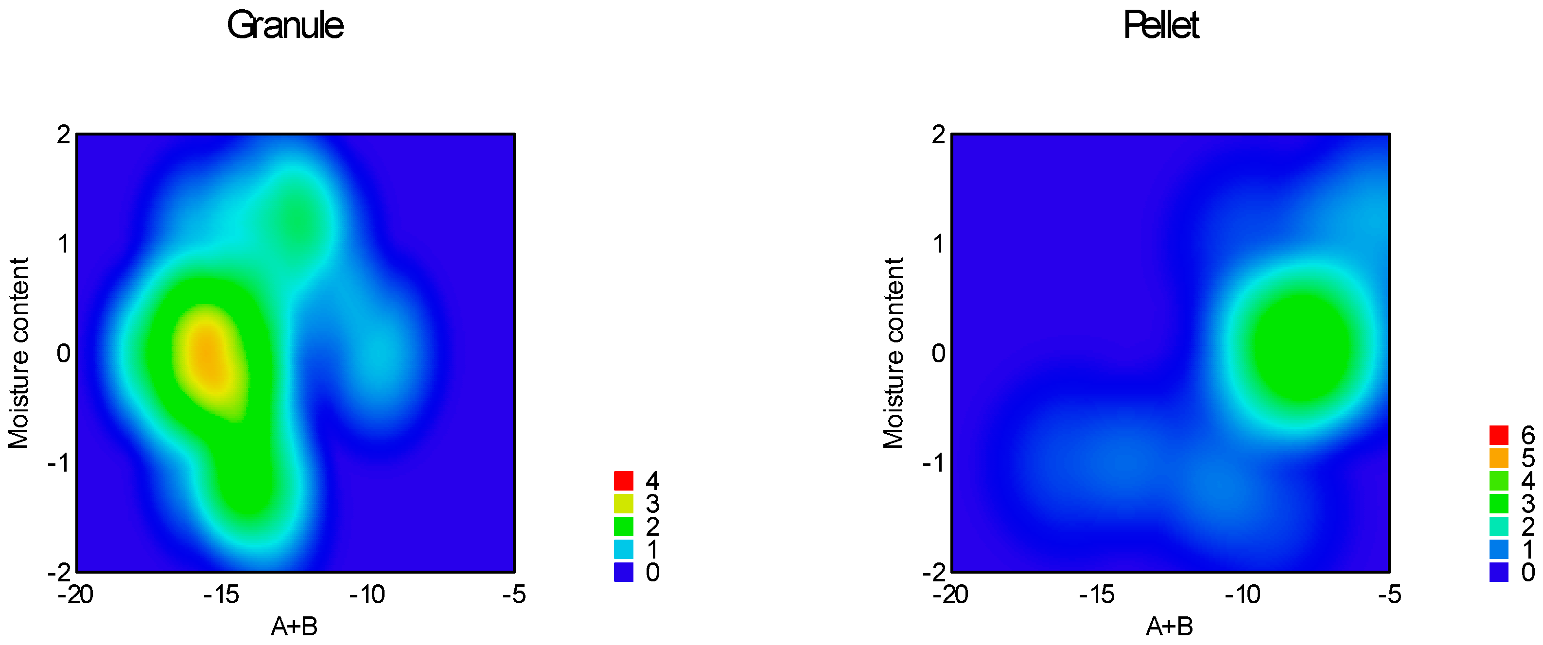
Heat map of effect of moisture content and sphericity on parameter ‘A+B’.
Figure 18.
Heat map of effect of moisture content and sphericity on parameter ‘A+B’.
Figure 19.
Image analysis of particle flow.
Figure 19.
Image analysis of particle flow.
Table 1.
Results of static angle of repose and flow time measurement.
Table 1.
Results of static angle of repose and flow time measurement.
| Sample |
SAOR (°) |
FT (s) |
| 1 |
38,77 |
18,31 |
| 2 |
37,14 |
18,62 |
| 3 |
34,78 |
19,75 |
| 4 |
34,02 |
20,33 |
| 5 |
39,77 |
19,15 |
| 6 |
34,28 |
22,83 |
| 7 |
40,02 |
19,78 |
| 8 |
39,10 |
19,10 |
| 9 |
36,45 |
18,95 |
| 10 |
36,10 |
18,84 |
| 11 |
36,08 |
18,88 |
| 12 |
35,84 |
18,62 |
| 13 |
35,54 |
11,72 |
| 14 |
29,38 |
10,70 |
| 15 |
30,02 |
9,76 |
| 16 |
31,93 |
13,80 |
| 17 |
32,75 |
10,49 |
| 18 |
31,38 |
14,79 |
| 19 |
33,85 |
12,32 |
| 20 |
32,29 |
10,70 |
| 21 |
29,25 |
10,55 |
| 22 |
34,65 |
11,73 |
| 23 |
29,44 |
9,64 |
| 24 |
32,90 |
10,60 |
Table 3.
Summarized results of avalanche behaviour.
Table 3.
Summarized results of avalanche behaviour.
| Sample |
Avalanche amplitude (pixel) |
Avalanche wavelength (time/0,04) |
Avalanche count |
| 1 |
5,47 |
25,17 |
18,00 |
| 2 |
7,00 |
23,29 |
24,00 |
| 3 |
7,54 |
22,73 |
26,00 |
| 4 |
5,39 |
22,86 |
28,00 |
| 5 |
5,38 |
22,27 |
26,00 |
| 6 |
6,07 |
20,03 |
32,00 |
| 7 |
5,09 |
24,94 |
18,00 |
| 8 |
7,43 |
23,86 |
21,00 |
| 9 |
6,98 |
24,37 |
19,00 |
| 10 |
5,71 |
22,61 |
18,00 |
| 11 |
6,65 |
22,05 |
21,00 |
| 12 |
9,07 |
20,67 |
15,00 |
| 13 |
6,08 |
19,11 |
35,00 |
| 14 |
4,54 |
17,00 |
32,00 |
| 15 |
3,80 |
21,56 |
25,00 |
| 16 |
7,51 |
21,45 |
29,00 |
| 17 |
7,37 |
20,00 |
26,00 |
| 18 |
7,96 |
22,24 |
29,00 |
| 19 |
6,94 |
19,08 |
24,00 |
| 20 |
6,62 |
17,96 |
27,00 |
| 21 |
8,52 |
15,19 |
32,00 |
| 22 |
7,19 |
15,55 |
29,00 |
| 23 |
4,79 |
20,64 |
22,00 |
| 24 |
8,29 |
21,33 |
21,00 |
Table 4.
Summarized parameters of non-linear fitting of flow curves.
Table 4.
Summarized parameters of non-linear fitting of flow curves.
| Sample |
a |
b |
c |
a+b |
AUFC |
| 1 |
-36,85 |
25,05 |
0,43 |
-11,79 |
26031,05 |
| 2 |
-46,14 |
30,57 |
0,40 |
-15,57 |
26326,58 |
| 3 |
-36,95 |
21,26 |
0,45 |
-15,70 |
24242,23 |
| 4 |
-41,38 |
27,56 |
0,40 |
-13,81 |
25211,94 |
| 5 |
-45,18 |
30,37 |
0,39 |
-14,81 |
26181,58 |
| 6 |
-23,75 |
14,11 |
0,50 |
-9,64 |
21505,26 |
| 7 |
-35,44 |
21,73 |
0,45 |
-13,71 |
24494,15 |
| 8 |
-39,72 |
26,23 |
0,42 |
-13,50 |
26183,06 |
| 9 |
-39,30 |
26,23 |
0,42 |
-13,07 |
25623,30 |
| 10 |
-41,21 |
26,06 |
0,42 |
-15,16 |
25164,99 |
| 11 |
-41,11 |
24,32 |
0,43 |
-16,79 |
25313,01 |
| 12 |
-42,45 |
25,18 |
0,43 |
-17,27 |
24918,38 |
| 13 |
-36,97 |
27,37 |
0,41 |
-9,61 |
26429,78 |
| 14 |
-57,80 |
41,95 |
0,34 |
-15,85 |
26903,19 |
| 15 |
-35,86 |
30,09 |
0,39 |
-5,77 |
27293,46 |
| 16 |
-36,16 |
23,92 |
0,42 |
-12,23 |
23353,74 |
| 17 |
-38,38 |
29,08 |
0,40 |
-9,29 |
27599,63 |
| 18 |
-28,46 |
21,37 |
0,43 |
-7,09 |
22905,91 |
| 19 |
-35,44 |
27,27 |
0,42 |
-8,17 |
27146,24 |
| 20 |
-44,48 |
35,10 |
0,38 |
-9,39 |
28408,06 |
| 21 |
-37,71 |
32,49 |
0,39 |
-5,22 |
27732,51 |
| 22 |
-35,58 |
27,30 |
0,42 |
-8,28 |
27499,81 |
| 23 |
-38,33 |
31,85 |
0,39 |
-6,48 |
27690,18 |
| 24 |
-39,49 |
30,95 |
0,39 |
-8,54 |
27571,28 |
Table 5.
Correlation of parameters of non-linear fitting and empirical measurements.
Table 5.
Correlation of parameters of non-linear fitting and empirical measurements.
| |
a |
b |
c |
AUFC |
a+b |
av. wav. |
av. amp. |
av. count |
SAOR |
FT |
| a |
Pearson corr. |
1 |
-0,808**
|
0,749**
|
-0,499*
|
0,515*
|
0,12 |
0,33 |
0,096 |
0,01 |
0,16 |
| Sig. |
|
0 |
0 |
0,013 |
0,01 |
0,576 |
0,115 |
0,654 |
0,964 |
0,456 |
| b |
Pearson corr. |
-0,808**
|
1 |
-0,970**
|
0,808**
|
0,089 |
-0,440*
|
-0,495*
|
0,151 |
-0,413*
|
-0,651**
|
| Sig. |
0 |
|
0 |
0 |
0,679 |
0,032 |
0,014 |
0,481 |
0,045 |
0,001 |
| c |
Pearson corr. |
0,749**
|
-0,970**
|
1 |
-0,764**
|
-0,145 |
0,39 |
0,513*
|
-0,171 |
0,456*
|
0,690**
|
| Sig. |
0 |
0 |
|
0 |
0,499 |
0,06 |
0,01 |
0,426 |
0,025 |
0 |
| AUFC |
Pearson corr. |
-0,499*
|
0,808**
|
-0,764**
|
1 |
0,333 |
-0,417*
|
-0,271 |
-0,029 |
-0,247 |
-0,701**
|
| Sig. |
0,013 |
0 |
0 |
|
0,111 |
0,043 |
0,2 |
0,893 |
0,245 |
0 |
| a+b |
Pearson corr. |
0,515*
|
0,089 |
-0,145 |
0,333 |
1 |
-0,437*
|
-0,162 |
0,383 |
-0,585**
|
-0,677**
|
| Sig. |
0,01 |
0,679 |
0,499 |
0,111 |
|
0,033 |
0,449 |
0,065 |
0,003 |
0 |
| av. wav. |
Pearson corr. |
0,12 |
-0,440*
|
0,39 |
-0,417*
|
-0,437*
|
1 |
0,048 |
-0,622**
|
0,623**
|
0,646**
|
| Sig. |
0,576 |
0,032 |
0,06 |
0,043 |
0,033 |
|
0,824 |
0,001 |
0,001 |
0,001 |
| av. amp. |
Pearson corr. |
0,33 |
-0,495*
|
0,513*
|
-0,271 |
-0,162 |
0,048 |
1 |
-0,203 |
0,408*
|
0,36 |
| Sig. |
0,115 |
0,014 |
0,01 |
0,2 |
0,449 |
0,824 |
|
0,341 |
0,048 |
0,084 |
| av. count |
Pearson corr. |
0,096 |
0,151 |
-0,171 |
-0,029 |
0,383 |
-0,622**
|
-0,203 |
1 |
-0,501*
|
-0,353 |
| Sig. |
0,654 |
0,481 |
0,426 |
0,893 |
0,065 |
0,001 |
0,341 |
|
0,013 |
0,091 |
| SAOR |
Pearson corr. |
0,01 |
-0,413*
|
0,456*
|
-0,247 |
-0,585**
|
0,623**
|
0,408*
|
-0,501*
|
1 |
0,728**
|
| Sig. |
0,964 |
0,045 |
0,025 |
0,245 |
0,003 |
0,001 |
0,048 |
0,013 |
|
0 |
| FT |
Pearson corr. |
0,16 |
-0,651**
|
0,690**
|
-0,701**
|
-0,677**
|
0,646**
|
0,36 |
-0,353 |
0,728**
|
1 |
| Sig. |
0,456 |
0,001 |
0 |
0 |
0 |
0,001 |
0,084 |
0,091 |
0 |
|
Table 6.
Experimental design.
Table 6.
Experimental design.
| |
Factor x1
|
Factor x2
|
Factor x3
|
Factor x4
|
| Sample |
Particle size |
Moisture content |
Glidant/Lubricant content |
Granule (-1)
Pellet (1) |
| 1 |
1100.0 |
3.0 |
-1.0 |
-1 |
| 2 |
1100.0 |
1.0 |
1.0 |
-1 |
| 3 |
350.0 |
3.0 |
1.0 |
-1 |
| 4 |
350.0 |
1.0 |
-1.0 |
-1 |
| 5 |
725.0 |
2.0 |
0.0 |
-1 |
| 6 |
194.7 |
2.0 |
0.0 |
-1 |
| 7 |
1255.3 |
2.0 |
0.0 |
-1 |
| 8 |
725.0 |
0.6 |
0.0 |
-1 |
| 9 |
725.0 |
3.4 |
0.0 |
-1 |
| 10 |
725.0 |
2.0 |
-1.4 |
-1 |
| 11 |
725.0 |
2.0 |
1.4 |
-1 |
| 12 |
725.0 |
2.0 |
0.0 |
-1 |
| 13 |
1100.0 |
3.0 |
-1.0 |
1 |
| 14 |
1100.0 |
1.0 |
1.0 |
1 |
| 15 |
350.0 |
3.0 |
1.0 |
1 |
| 16 |
350.0 |
1.0 |
-1.0 |
1 |
| 17 |
725.0 |
2.0 |
0.0 |
1 |
| 18 |
194.7 |
2.0 |
0.0 |
1 |
| 19 |
1255.3 |
2.0 |
0.0 |
1 |
| 20 |
725.0 |
0.6 |
0.0 |
1 |
| 21 |
725.0 |
3.4 |
0.0 |
1 |
| 22 |
725.0 |
2.0 |
-1.4 |
1 |
| 23 |
725.0 |
2.0 |
1.4 |
1 |
| 24 |
725.0 |
2.0 |
0.0 |
1 |
Table 7.
Glidant/lubricant content of granules.
Table 7.
Glidant/lubricant content of granules.
| Factors coded value |
-1.4 |
-1.0 |
0.0 |
1.0 |
1.4 |
| Talc content % |
0 |
1.25 |
2.5 |
3.75 |
5 |
| Mg-stearate content % |
5 |
3.75 |
2.5 |
1.25 |
0 |
|
Disclaimer/Publisher’s Note: The statements, opinions and data contained in all publications are solely those of the individual author(s) and contributor(s) and not of MDPI and/or the editor(s). MDPI and/or the editor(s) disclaim responsibility for any injury to people or property resulting from any ideas, methods, instructions or products referred to in the content. |
© 2024 by the authors. Licensee MDPI, Basel, Switzerland. This article is an open access article distributed under the terms and conditions of the Creative Commons Attribution (CC BY) license (http://creativecommons.org/licenses/by/4.0/).
