1. Introduction
As the population density continues to rise, the demand for electrical power experiences significant growth. In response to this challenge, electric companies are constantly seeking innovations to enhance the ampacity of their transmission and distribution systems to meet the growing demand. In densely populated environments, underground transmission lines emerge as the preferred option due to their greater ease of installation compared to traditional overhead lines.
In these systems, the ampacity of power cables primarily depends on the cross-sectional area of the conductor core. To ensure that the specified ampacity is achieved, designers must carefully assess cable parameters, especially the appropriate cross-sectional area of the conductor core [
1].
The ampacity of power cables has been extensively discussed in the literature and is governed by various international standards [
2]. Different analytical and numerical approaches are employed to calculate cable ampacity, with analytical methods widely endorsed by prominent international standardization associations such as IEEE and IEC [
2,
3,
4]. Calculation procedures in both standards exhibit similarities and are based on the model proposed by Neher and McGrath [
6].
Over time, various specialized software tools have been developed to calculate ampacity in different cable configurations, considering various soil layers and installation conditions, exemplified by programs like CYMCAP [
7,
8] and ETAP [
5]. The history of ampacity calculations is extensively documented in the literature, addressing in detail various factors affecting cable ampacity [
2,
7].
Cable ampacity has been found to be closely related to installation conditions and material properties [
7,
10,
11]. In particular, the thermal resistivity of the soil is a critical factor in the thermal analysis of cables [
12]. Over 70% of the conductor temperature rise in buried cables is attributed to external thermal resistance [
2,
12]. Heat dissipation from the conductor and other metallic sheaths is essential through the cable insulation and the surrounding soil. Although some types of soil naturally exhibit high thermal resistivity, the use of backfill materials has been shown to reduce this resistivity, enhancing heat dissipation capacity [
14].
The use of backfill materials with lower thermal resistivity than the surrounding soil is a conventional practice to manage the thermal environment around cables and improve their ampacity [
2,
13,
15]. This effectiveness is especially pronounced in native soils with high thermal resistivity or in dry soil and low-temperature conditions [
2,
7]. However, an increase in the volume of backfill material can lead to higher installation costs, especially in urban areas with space limitations [
16], and backfill materials also entail significant manufacturing costs. Therefore, it is necessary to optimize various parameters, such as the amount of backfill material and installation dimensions, to achieve optimal cable ampacity at a reasonable cost.
Various mathematical models have been developed to optimize both cable ampacity and installation dimensions. In [
17], a model is presented that selects the optimal cross-sectional area of the conductor and corrective backfill dimension. On the other hand, in [
15], a methodology is proposed to optimize the thermal performance of power cables based on configuration parameters. Additionally, the impact of controlled backfill quantity on the thermal resistivity of native soil has been investigated [
12,
18], as well as the ampacity of high-voltage cables in relation to cable spacing, burial depth, and backfill size [
19,
20,
21].
The optimization of parameters in underground cable transmission lines is a crucial topic in the electrical industry. Despite the demonstrated effectiveness of Genetic Algorithms (GA) and Particle Swarm Optimization (PSO) in numerous studies [
23], none have addressed the optimization of cable ampacity through the combination of PSO with implementation improvements, such as adaptive penalty functions to manage constraints with fewer parameter adjustments, as well as advanced adaptive restart strategies and parameter self-adaptation. Furthermore, these previous studies have not considered crucial variables such as mutual heating between cables [
22], sheath installation type, and economic constraints on installation cost as a nonlinear function.
Therefore, this article proposes an innovative mathematical formulation that addresses these deficiencies. The optimization of power cable ampacity is integrated using the PSO algorithm with significant improvements in implementation. Subsequently, it is compared with the traditional PSO algorithm in MATLAB, providing a meaningful comparative evaluation between both methods. The central focus is on improving cable ampacity through adjustments in the dimensions of thermal backfill rather than increasing the cross-sectional area of the cable core.
2. Cable arrangement and model
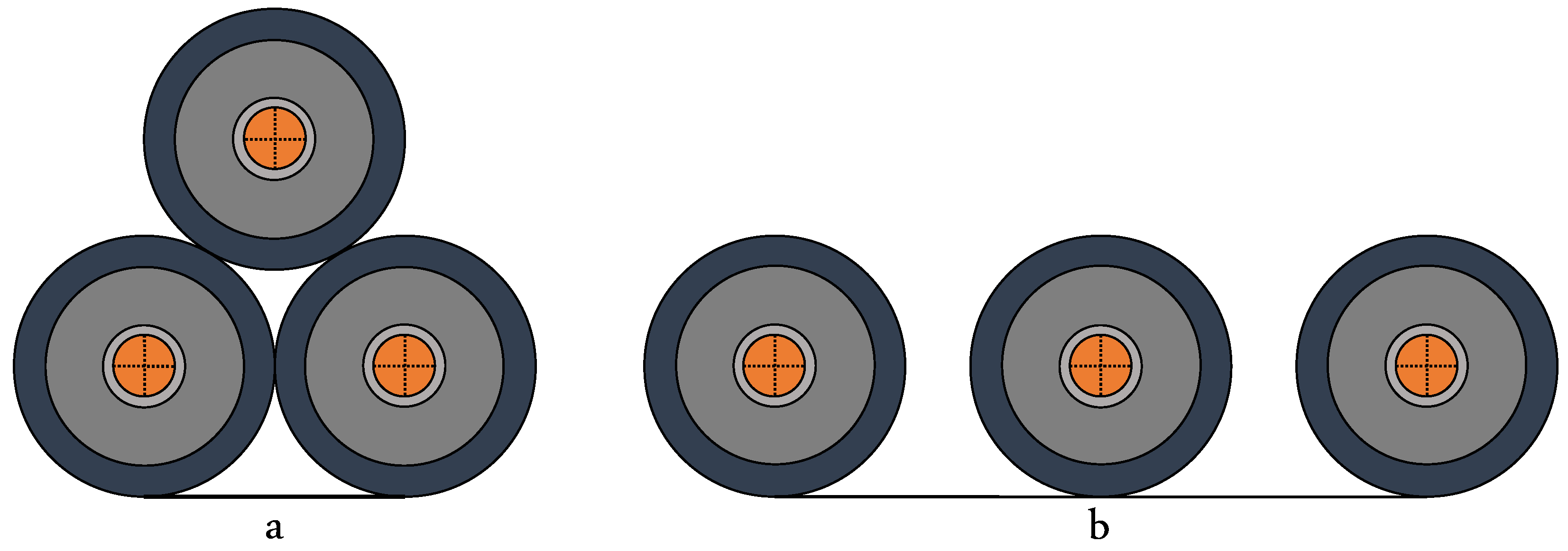
There are different configurations in which underground electrical cables can be installed in connection with a three-phase transmission line. Among the most common formations are trefoil arrangement (
Figure 1a) and flat arrangement (
Figure 1b). Each cable formation has its own advantages and disadvantages. According to a source [
24], in the flat formation, both with and without thermal backfill, the temperature rise is lower compared to the trefoil formation. This is because in the trefoil arrangement, adjacent cables that touch each other raise the temperature of the sheath due to internal conduction.
The use of backfill has a significant effect in reducing temperature in the underground electrical cable system. To achieve effective heat transfer from the cables, natural soil is generally replaced by a thermal backfill with a relatively low thermal resistivity, less than 1.0 K·m/W [
1,
2].
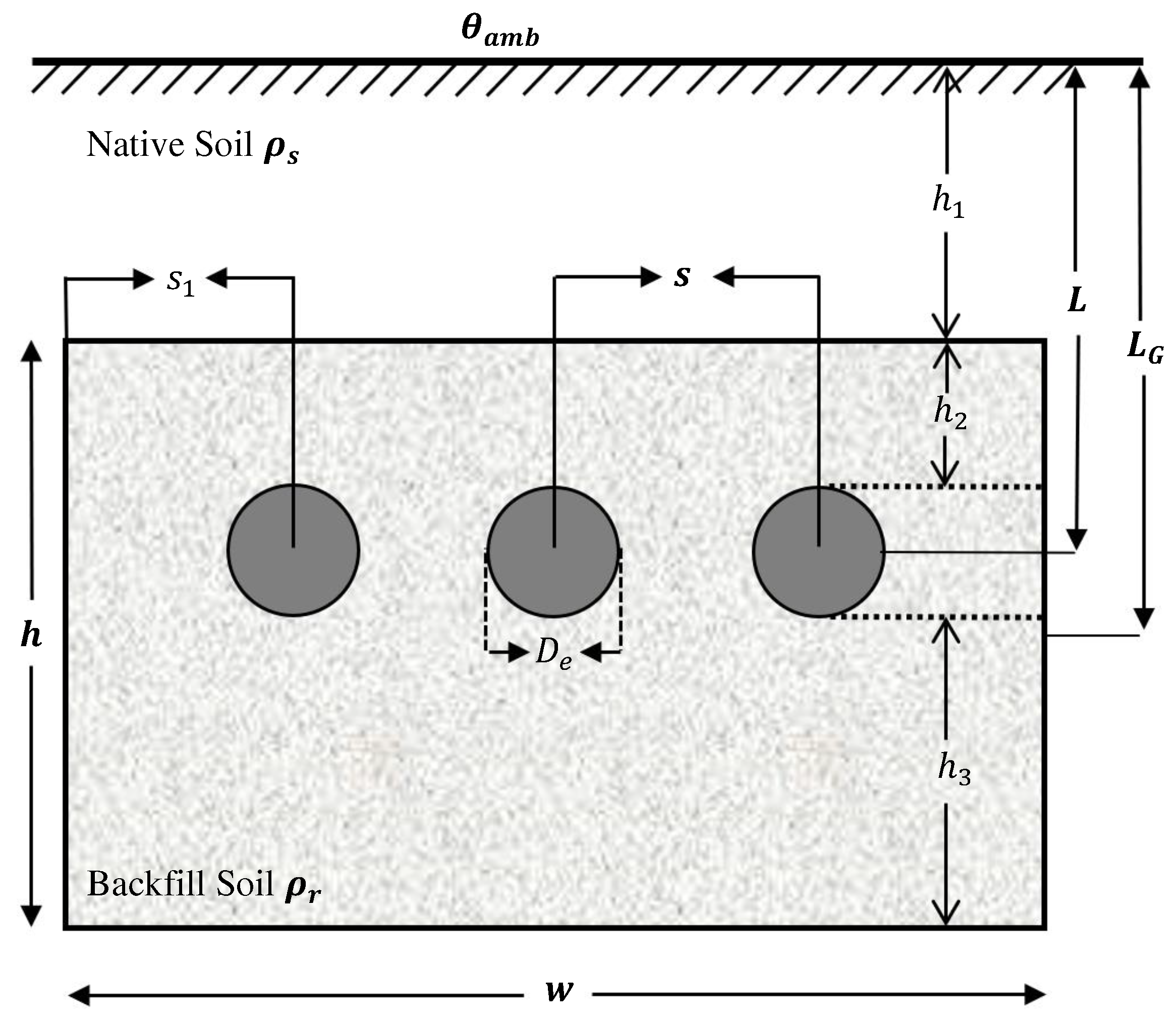
In
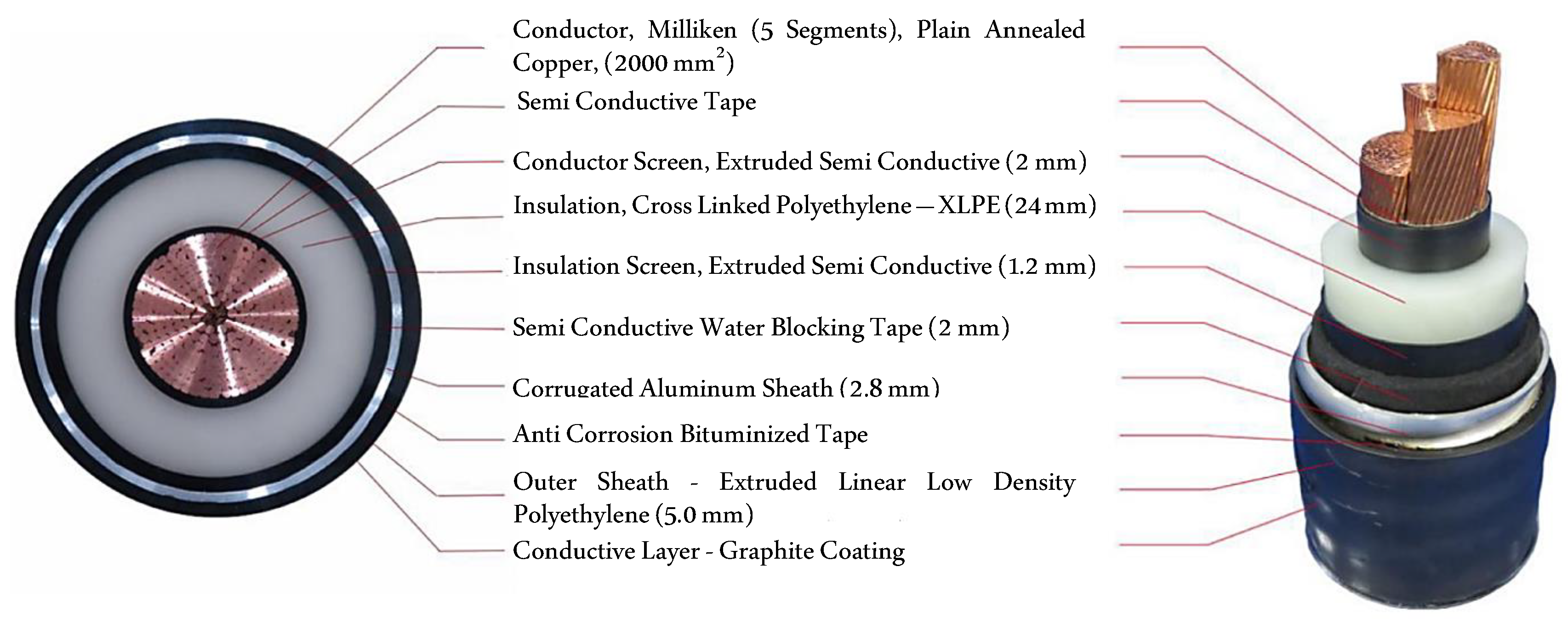
Figure 2, the installation method with regular transposition and arrangement of cables, along with all relevant variables for the optimization problem, is shown. Additionally, a segmented conductor cable model (see
Figure 3) is used to minimize skin and proximity effects in conductors with large cross-sections [
25]. The thermal and electrical parameters of the cable are detailed in
Table 1, based on manufacturer specifications [
26].
The cable depicted in is a segmented compacted copper conductor, with a screen made of extruded semiconductor. The insulation of the cable is made of a high-quality dry-cured XLPE compound, which is resistant to heat, moisture, and abrasion. The insulation is shielded by a semiconductor tape that is firmly adhered to it. Additionally, the outer covering of the cable is composed of a thermoplastic material (such as PVC, PE, or similar materials) that is continuously extruded over the metallic layer or moisture barrier of the cable.
3. Method
3.1. Ampacity Calculation
To understand the ampacity of cables in underground systems, it is crucial to examine the heat generation resulting from the current flow through the conductor. This thermal efficiency, along with the temperature limits of the insulation, is directly related to the cable’s ampacity. In the context of underground cables in homogeneous soils, heat transfer occurs primarily through conduction across the cable components and the surrounding soil. When formulating the problem in two dimensions due to the significantly greater length than the cable diameter, heat conduction in the soil is described by the differential equation [
2]:
where
is the thermal resistivity in K·m/W,
is the heat flux generated in J/s, and
c is the volumetric heat capacity.
When solving the heat transfer equation for underground cables, the temperature around the cable is estimated—an essential aspect for evaluating compliance with insulation temperature limits and, consequently, determining ampacity.
The solution to this equation allows estimating the cable temperature at any point around it, a crucial factor in evaluating compliance with insulation temperature limits and, consequently, determining cable ampacity. Two methods are employed to solve Eq. 1: the analytical method, providing exact solutions in closed mathematical form, and the numerical method [
8]. While the analytical method, though precise, has limitations for complex and realistic problems, especially when the geometry of the arrangement of underground cables is complicated. In contrast, the numerical method, although requiring iterations for approximate solutions, offers flexibility to analyze complex cable systems and apply more realistic boundary conditions. A practical solution to the heat dissipation problem leverages the fundamental similarity between heat flow due to the temperature difference between the conductor and its surroundings and the flow of electric current caused by a potential difference [
2]. Given the complexity of the ampacity problem, the solution proposed by Neher and McGrath in 1957 remains foundational, forming the basis for IEEE and IEC standards [
3].
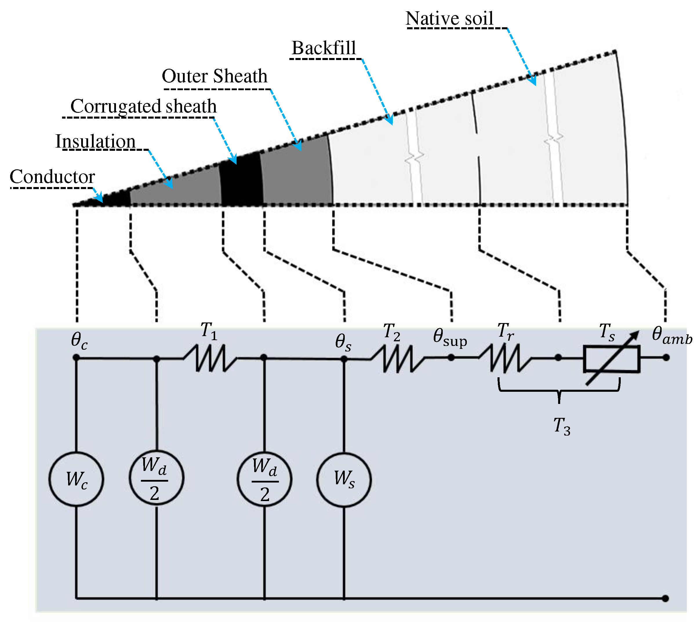
The
Figure 4 presents the thermo-electric equivalence network of the cable and its surroundings. In this representation, the losses in the conductor, corrugated aluminum sheath, and dielectric are denoted as
,
, and
(W/m), respectively. Additionally, the thermal resistances per unit length,
,
, and
(K·m/W), are shown, corresponding to the thermal resistance of the insulation layer, the thermal resistance of the cable’s outer sheath, and the thermal resistance between the cable surface and the surrounding medium.
In the specific case of a cable with corrugated aluminum sheath (with an armor loss factor
= 0), the losses can be expressed by the equation:
where
, the sheath loss factor, is defined as the ratio of the total losses in the metallic sheath to the total losses in the conductor.
In practice, non-conductive layers of the cable, such as insulation and the separating cover, impede the heat flow from the cables. These layers generally have a cylindrical shape. If we consider a constant thermal resistivity
and the inner and outer radii of a layer as
and
respectively, the thermal resistance of a cylindrical layer per unit length can be calculated using the reference [
6].
The thermal resistance of the metallic parts of the cable, although not equal to zero, is often negligible in ampacity calculations [
9]. Ampacity is determined by considering the calculation of temperature-dependent conductor loss
, and we obtain:
where
is the allowed temperature rise of the cable conductor above the ambient temperature.
n denotes the number of conductors in the cable. The dielectric loss (
) and the alternating current electrical resistance (
) of the metallic parts of the cable are calculated using the corresponding equations:
where:
The correction factors for the proximity effect (
) and the skin effect (
) vary depending on the type of cable, as detailed in references [
1,
11]. Additionally, the parameter
, highlighted as one of the most relevant and effective, is influenced by the backfill dimensions, the distance between cables (
s), and the cable model with corrugated sheath [
23]. This loss factor (
) consists of losses due to circulating currents (
) and Foucault currents (
) [
3,
28]. For three single-core cables, as illustrated in
Figure 2, the loss factor due to Foucault currents is calculated as follows [
2]:
3.2. Thermal external resistance
When the burial depth of the cable (
L) significantly exceeds its external diameter (
) in soil with resistivity
, the thermal resistance of the surrounding medium can be calculated using Eq. 3, replacing
with
and
with
. To enhance heat dissipation in buried cables, it is common to replace part of the native soil around the cables with a thermal backfill material [
14]. This is because the external thermal resistance contributes to over 70% of the temperature rise in the conductor of buried cables [
2,
13]. In practice, high-voltage cables are often placed in backfill material to improve heat dissipation and reduce thermal resistance.
Figure 2 illustrates cables arranged on backfill, and the external thermal resistance is described by the equation [
2]:
where
N is the number of cables in the backfill envelope, and
represents the depth of the center of the rectangular backfill measured from the ground surface. The geometric factor
encompasses all design parameters through the values of
and the equivalent radius
. This concept was initially introduced in [
6] as an integral part of backfill analysis.
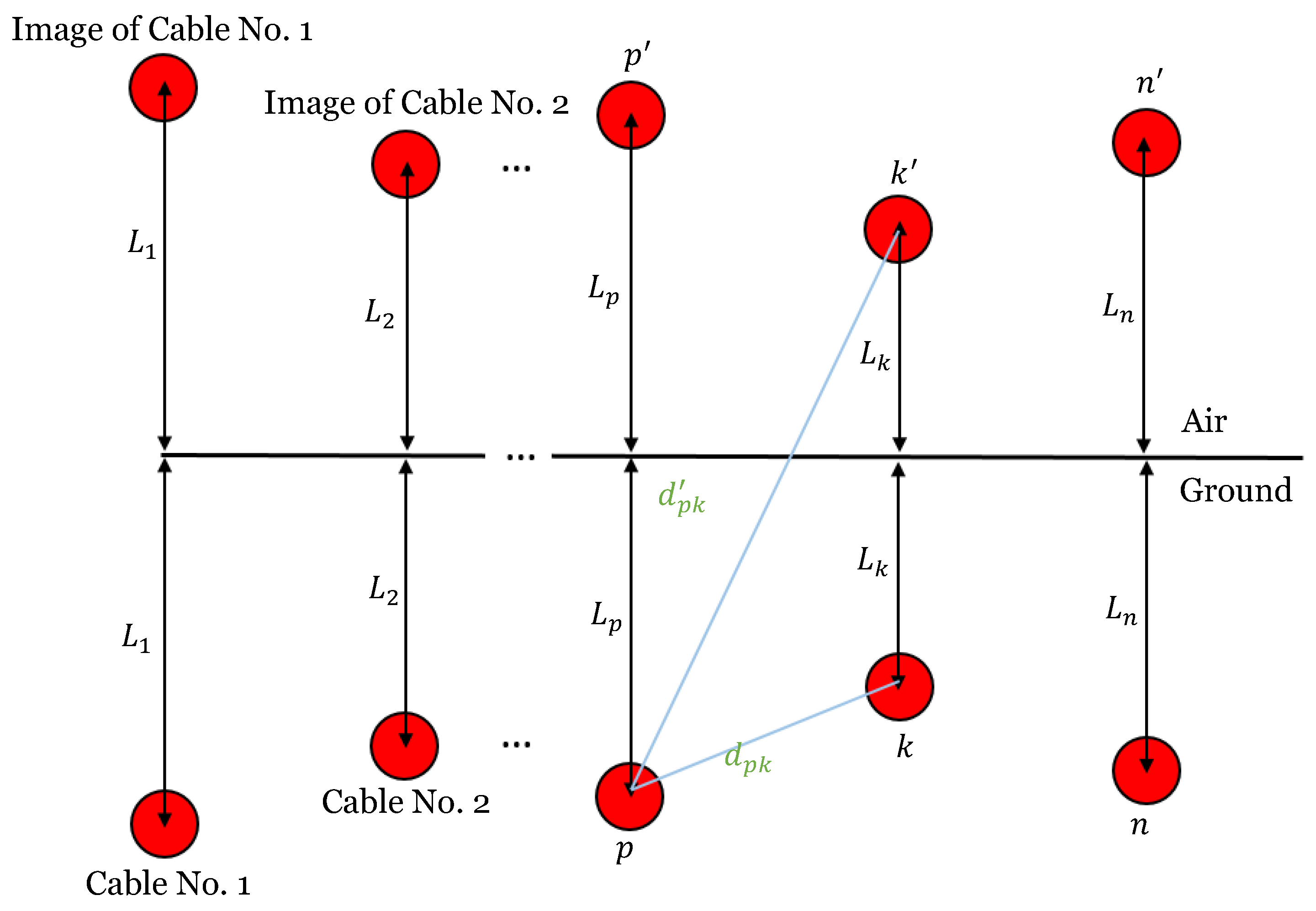
For a single-core cable buried under an isothermal plane, the factor
F represents the mutual heating effect of other cables in a system with equal load, and for cable
p, it is expressed as:
and
cable distances and fictitious images shown in
Figure 5.
4. Development of the Proposed Approach
The innovation of this article lies in the presentation of an advanced algorithm designed to optimize the ampacity of underground cables specifically allocated in the backfill. This pioneering approach accurately addresses the challenges associated with determining the optimal dimensions of the trench, thermal backfill, and cable ampacity, especially in unfavorable environments for high-voltage transmission, considering comprehensively economic and physical installation constraints.
4.1. Formulation of the Objective Function
Equations (4) and (7) are directly influenced by the characteristics of the backfill and the thermal conductivity properties of the soil. Some parameters, such as the thermal resistivity of the soil and ambient temperature, are inherently random, fluctuating along the cable route due to climatic and seasonal variations. In this study, we will assume these parameters to be constants.
In the evolutionary metaheuristic algorithms community, various approaches have been proposed, with the use of penalty functions being the most common. However, these functions have drawbacks, such as the need to adjust multiple parameters, complicating the search for the optimal combination [
39,
41]. Additionally, solution exploration can be slow, with no guarantee of reaching the optimal solution. To overcome these limitations, modifications to algorithms have been made by introducing the concept of parameter-free penalty functions [
39,
40,
42]. These penalty strategies play a crucial role in balancing the optimization of the objective function and compliance with constraints. In our research, we specifically evaluate adaptive penalization, focusing on the penalty function given by:
The introduction of the penalization parameter
(a significantly large number) aims to ensure that the violation of the constraint
is of a similar order of magnitude to the value of the objective function
. In the case of equality constraints, it is commonly addressed by converting them into approximations of inequality constraints, following the form
. This implies an increase in the total number of inequality constraints to
, where
q is the initial number of inequality constraints, and
m is the number of equality constraints. Therefore, the term
q in equation (
9) is replaced by
j to incorporate both inequality and equality constraints.
4.2. Formulation of Constraints
The design variables include the determination of various parameters, such as the depth of the backfill center (), cable depth (L), spacing between cables (s), backfill width and thickness (w, h), among others.
With the aim of achieving the optimal configuration and maximizing ampacity, the economic constraint of backfill and installation cost is incorporated as a crucial factor in the optimization method. Additionally, there are physical installation constraints that must be considered in the objective function and are expressed through the following equation:
where the cost function
C is calculated using the cost parameter values listed in
Table 2 and the information presented in
Figure 2. It is important to note that the total cost should not exceed the budget
, and physical and design limits are imposed on variables, as illustrated in
Figure 2 and detailed in
Table 3. The lower limit is determined by physical conditions, while the upper limit is constrained by the cost of backfill material in the optimization process [
2,
31]. Additionally, the ampacity constraint is simply expressed as:
.
4.3. Optimization Technique
Stochastic metaheuristic algorithms, such as Genetic Algorithm (GA) and Particle Swarm Optimization (PSO) [
36,
37,
38], have gained preference in real-world applications due to their mathematical simplicity, ability to tackle large-scale problems [
32], and their capability to achieve globally optimal solutions in short times [
35]. Although PSO is widely used and effective in various problems, it stands out for its fast convergence, ease of implementation, and fewer parameters compared to GA. Additionally, its balance between exploration and exploitation, effectiveness in continuous and discrete problems, and the ability to handle multimodal search spaces make it invaluable in various optimization applications.
The Particle Swarm Optimization (PSO) algorithm begins its execution by generating random solutions called particles. The population is represented as , where N indicates the population size, and T denotes transposition. Each particle represents an individual in the population and is described as , with D being the dimension of the search space.
PSO relies on individual experience (Pbest), collective experience (Gbest), and the current movement of particles to determine their next positions in the search space. Experiences are incorporated through two acceleration factors ( and ) and two random numbers generated in the interval [0,1]. Simultaneously, the current movement is modulated by an inertia factor (w), whose value varies between and . The initial velocity of the population is represented as . Therefore, the velocity of each particle is calculated as .
The following pseudocode presents an adapted version of the PSO algorithm for the optimization of underground cables. Two key elements are highlighted: dynamic parameter adaptation and adaptive restart. The fundamental steps of the included PSO are:
Set the parameters , , , and for PSO.
Initialize the population of particles with positions and velocities .
Set the iteration .
Calculate the fitness of particles for all i and find the index of the best particle b.
Set for all i, and .
Dynamically adapt the inertia parameter
-
Update the velocity and position of particles:
; and .
; and .
Evaluate fitness for all i and find the index of the best particle .
-
Update the population’s :
If , then , otherwise
-
Update the population’s :
If , then , and set , otherwise
Apply adaptive restart when fitness decreases.
If , then and go back to step 6, otherwise go to step 12.
Print the optimal solution as .
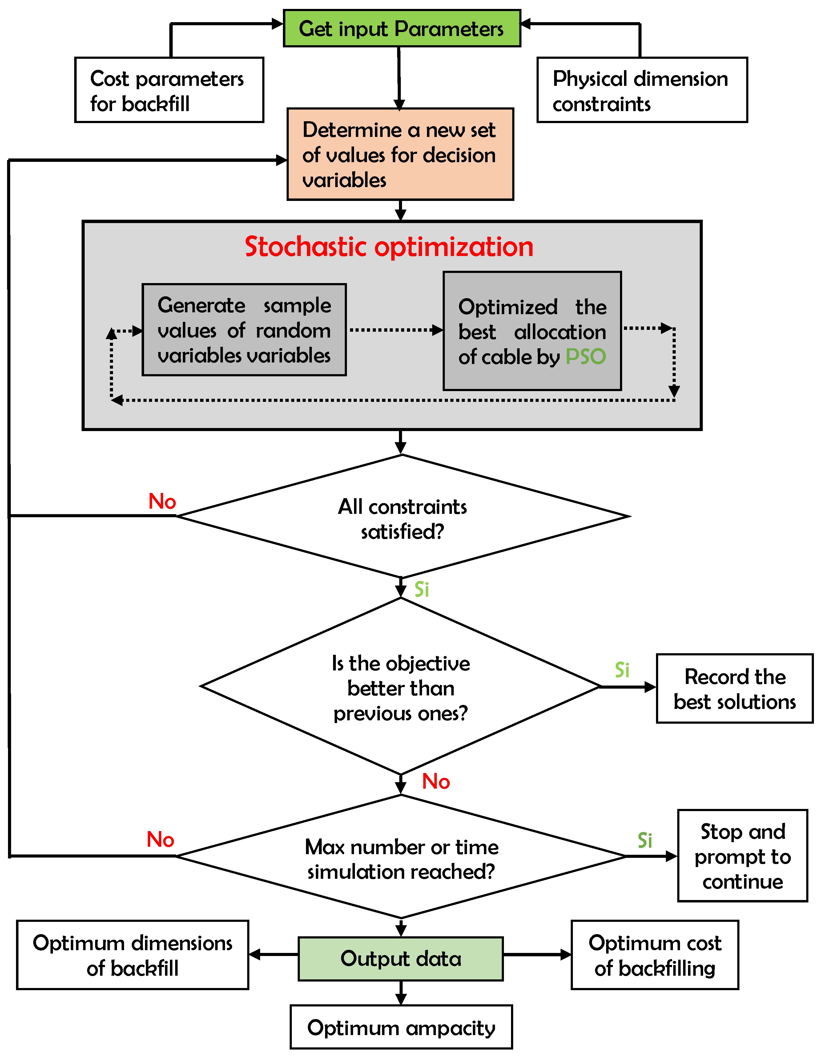
A flowchart (see
Figure 6) has been designed to facilitate the understanding of the optimization process adopted in this work. The flowchart illustrates the sequence of steps in the proposed algorithm, starting with the generation of an initial random set of individuals represented by particles. The optimization procedure is based on an iterative algorithm that uses the simulation model and previous results to generate a set of values that maximize the cable ampacity while ensuring they remain within physical limits and the available budget.
5. Simulation results
The proposed method was evaluated on the cable system shown in
Figure 2, based on the cable construction illustrated in
Figure 3. Design variables were constrained within a specific range detailed in
Table 3. An upper limit of ?
$300 was set for the installation cost (
). Constant parameters, such as the thermal resistivity of native soil under normal conditions (
K·m/W), thermal resistivity of the backfill (
K·m/W), and ambient temperature (
°C), were obtained from [
31].
The optimization problem is formulated as an objective function with self-adaptive penalization, presented in Eq. 9, where is defined according to Eq. 10 and takes the form .
This problem was addressed using the proposed PSO and the traditional PSO from MATLAB, the latter widely used in scientific research. All tests were conducted on MATLAB R2016a, running on an Intel(R) Core(TM) i7-8750H CPU @ 2.20 GHz, 2.21 GHz, with 12.00 GB of RAM. The implementation includes an enhanced algorithm with dynamic adaptation and adaptive restart.
The parameters of the PSO algorithm were carefully selected: a population of 100, inertial weight (w) ranging from 1 to 0.1, and modified acceleration coefficients ( and ) from 2 to 1. An adaptive restart strategy with a 2% probability at each iteration was implemented to encourage exploration. These specific values were chosen to enhance the convergence and effectiveness of the PSO algorithm in optimizing ampacity.
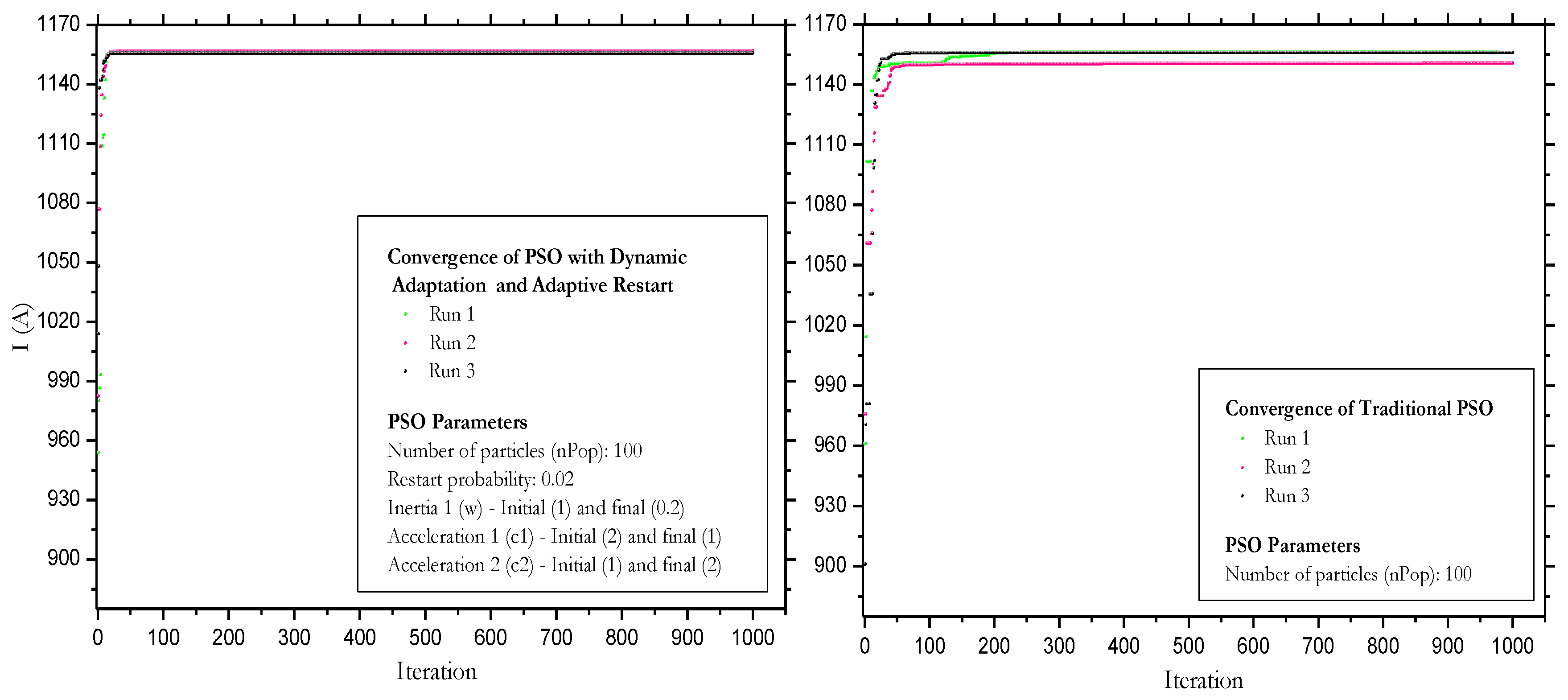
Three independent runs of the proposed PSO algorithm and the traditional PSO were conducted, as depicted in
Figure 7. From the 100 iterations onward, both algorithms exhibit notable stability over time, where solutions do not show significant improvements. This indicates that both algorithms converge towards an optimal solution more quickly in fewer iterations. Furthermore, in the figures, a slight variability in convergence is observed for the proposed algorithm, and higher variability is noted for the traditional PSO, attributable to its stochastic nature.
The enhanced implementation of the proposed algorithm, featuring dynamic adaptation and adaptive restart, contributes to stability and coherence by reducing fluctuations and enhancing convergence. Adaptive restart, strategically restarting particles, generates consistent and reliable results across various executions. Without these improvements, results tend to be more unstable. The effectiveness of dynamic adaptation and restart depends on the problem, making multiple runs and statistical analyses crucial for robust performance evaluation.
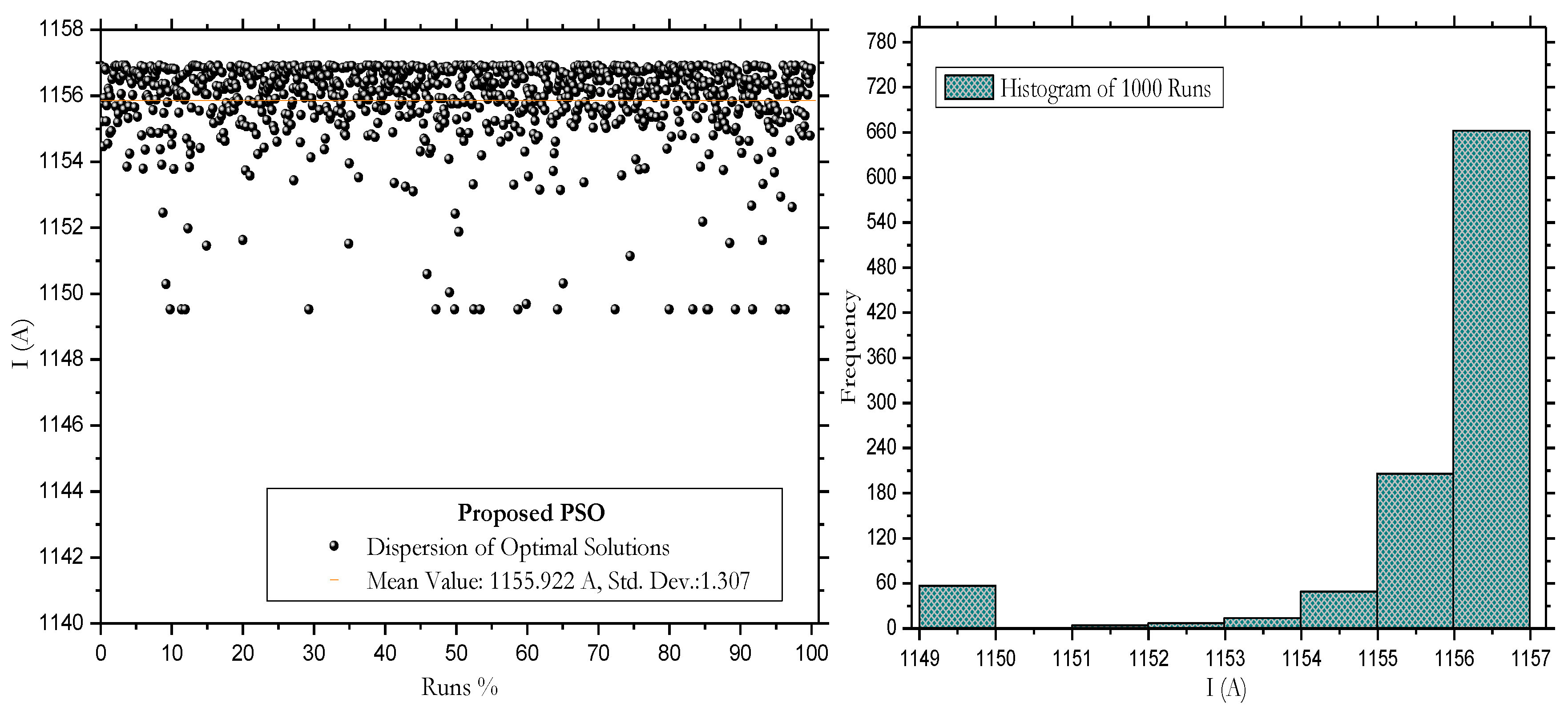
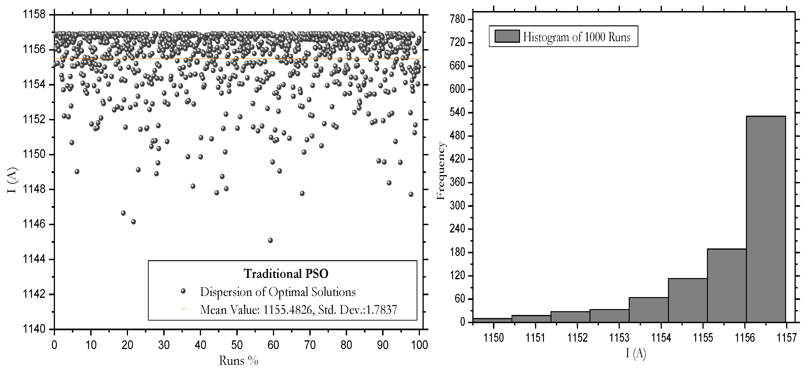
To assess performance, each algorithm was executed 1000 times. The optimal results, recorded for cable ampacity in each run, are visually presented in
Figure 8 and
Figure 9. Additionally, algorithm performances are detailed in
Table 4, providing crucial information such as the best ampacity value, average, standard deviation, among other relevant aspects.
When comparing results between the proposed PSO algorithm and the traditional PSO, notable differences in terms of accuracy, performance, and consistency are highlighted. The histogram analysis in
Figure 8b) and
Figure 9b reveals that the maximum value is most frequently recorded in the range of 1156 to 1157 A. The success probability for this interval is 66.1% in the proposed PSO and 56.4% in the traditional PSO, respectively. Although traditional PSO is 81% faster, the proposed PSO stands out for its accuracy. Despite being slower, its precise approach makes it ideal when accuracy is crucial. Additionally, its simplicity and clarity facilitate understanding and adjustment, being accessible with fewer parameters than the traditional approach. The introduction of restart probabilities and dynamic adaptation enhances the exploration of the search space, achieving more efficient convergences. This code is a valuable tool for intuitively and effectively addressing optimization problems.
Based on these comparisons and analyses, the proposed algorithm is selected as the most suitable, effective, and reliable for conducting comparisons in cable ampacity optimization with and without backfill. The notable results are presented in
Table 5.
Initially, the cable ampacity without considering backfill is 980.883 A. This would imply the need to use a conductor with a larger cross-sectional area to support a load current of 1000 A. However, by applying ampacity optimization considering the backfill configuration, the cable ampacity increases to 1156.9 A, making it suitable for a load current of 1000 A. Therefore, the percentage increase in the ampacity of the cable installed with backfill compared to the cable without backfill is approximately 18.45%. This highlights the benefits of backfill in cable ampacity optimization.
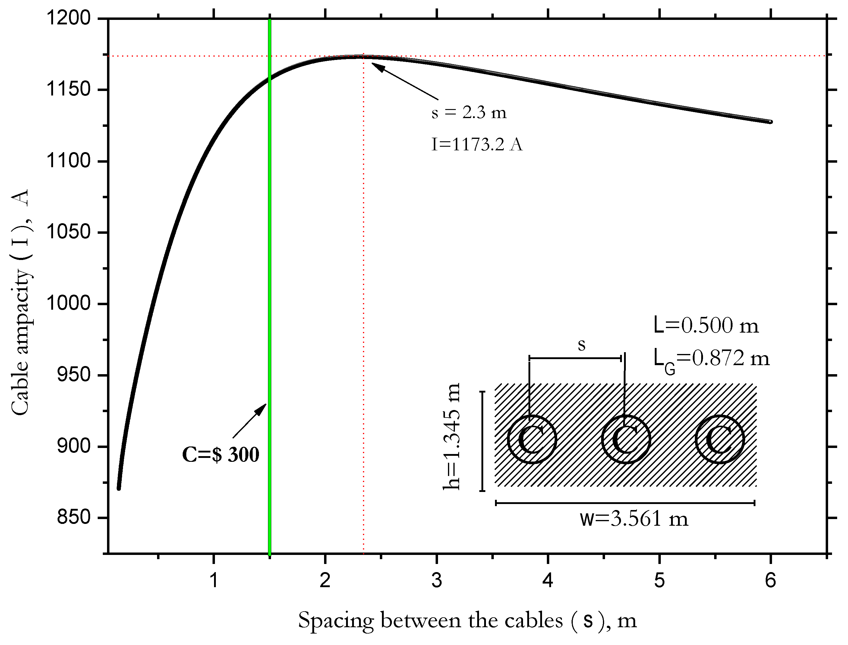
It is essential to note that increasing the backfill volume does not guarantee an unlimited increase in ampacity. The proximity effect influences the spacing between cables (s), and with a constant backfill width (w), current losses decrease due to better dissipation and reduced electrical resistance provided by the backfill. The optimum value of s that maximizes ampacity is reached when both effects balance each other.
Figure 10 indicates that ampacity is maximum at
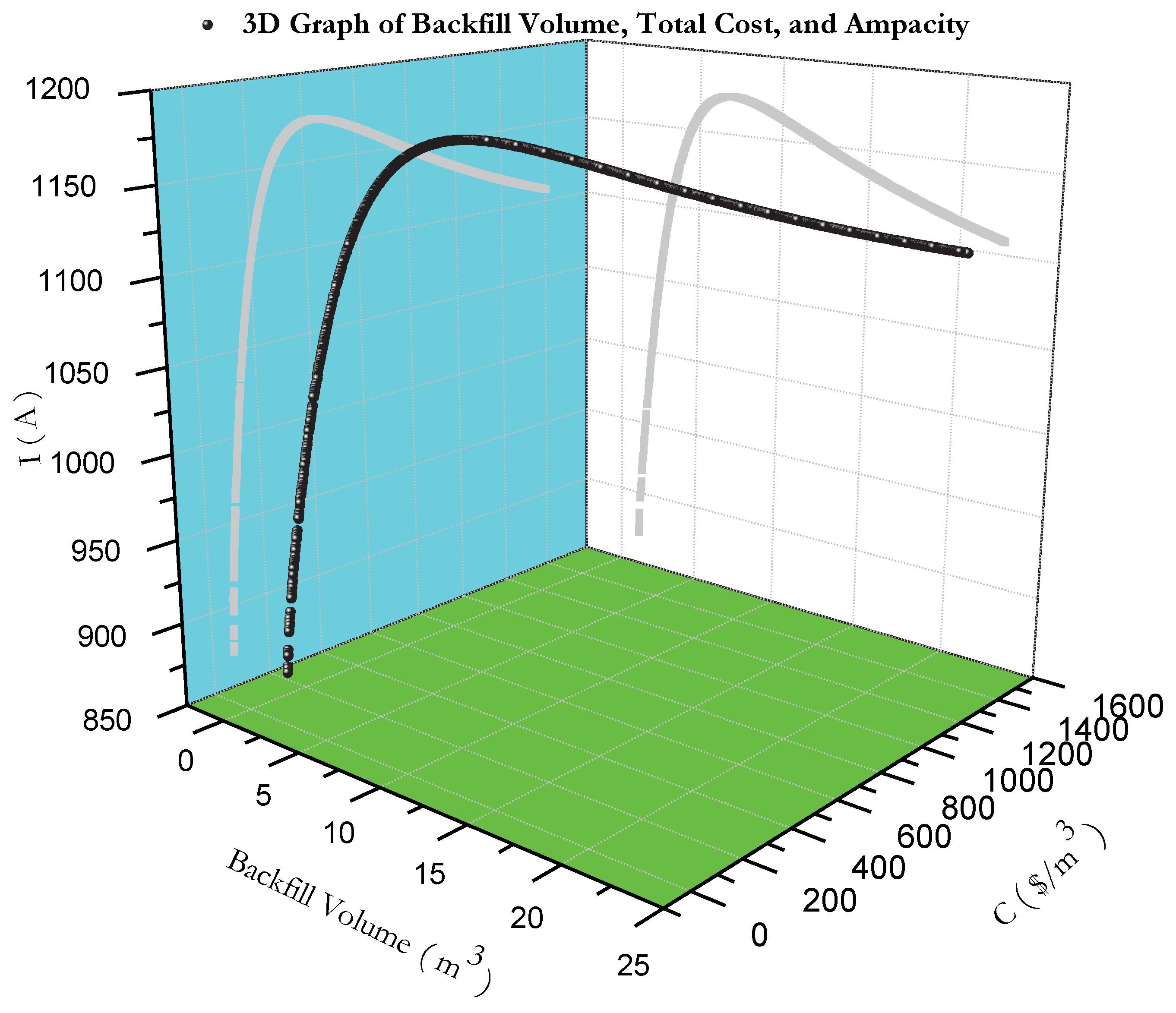
s=2.3 m, albeit at a high cost. Below this value, it decreases due to the proximity effect, while above it decreases due to increased thermal resistivity. The increase in backfill volume directly affects the total installation cost, influencing ampacity up to a balance point, beyond which it decreases (
Figure 11).
Our proposal suggests delaying or avoiding investments in larger-section cables for underground lines, focusing on the use of backfill materials to achieve optimal ampacity at a more favorable cost. Additionally, in places where cables are already overloaded, the addition of backfill could be considered instead of installing larger-section cables.
It is essential to consider that the cable ampacity is directly affected by climatic and geographical variations. By adjusting the thermal resistivity of the backfill material () to 0.6 K·m/W, an ampacity of 1135 A is obtained, and by modifying the value of to 2.6 K·m/W, the resulting ampacity is 1131 A; at an ambient temperature of 27°C, the ampacity is reduced to 1129 A. These factors significantly impact both the cable ampacity and the dimensions of the backfill material, requiring analysis through a probabilistic approach.
The choice to implement a customized version of the PSO algorithm instead of the standard MATLAB implementation is based on adapting the algorithm to specific requirements and achieving greater flexibility and performance, allowing more precise control in a particular context.
6. Conclusions
This study focuses on optimizing the ampacity in a 220 kV underground electrical cable system with XLPE insulation installed in thermal backfill. The PSO algorithms with adaptive penalty functions, dynamic adaptation, and adaptive restart were successfully implemented. The results indicate that the proposed approach efficiently achieves the optimal value of ampacity and design variables, demonstrating superior performance compared to traditional PSO, which exhibits greater variability in results.
The proposed method demonstrates more accurate and consistent results, with a success probability of 66.1% in finding the optimal ampacity value, compared to the 56.4% of the traditional approach. Furthermore, the traditional algorithm’s performance is 81% faster in terms of execution time than the proposed algorithm. An optimal ampacity of 1156.9 A was achieved for the cable with thermal backfill, with specific dimensions and a cost of $94.7/m.
The use of thermal backfill increased the cable’s ampacity by approximately 18.45% compared to the cable without thermal backfill. This proposal is applicable in both the design of new underground cable systems and the improvement of existing systems. Investing in thermal backfill may offer a more cost-effective alternative than investing in cables with a larger cross-sectional area. Moreover, this methodology is a valuable tool for engineers and professionals involved in the design and improvement of underground electrical systems, enhancing performance and reducing installation costs.
As future work, simultaneous optimization of cable cost and ampacity will be evaluated using a probabilistic approach. This will provide a more detailed and comprehensive insight for decision-making in the design and maintenance of underground cabling systems, further enhancing the proposal and contributing to advancements in electrical system optimization.
Author Contributions
Conceptualization, B.A. and M.T.; methodology, B.A.; software, B.A.; validation, B.A.; formal analysis, B.A.; investigation, B.A. and M.T.; resources, B.A.; original draft preparation, B.A.; writing—review and editing, B.A., M.T., D.T, D.M., E.U.; visualization, M.T. and C.R.; supervision, B.A.; All authors have read and agreed to the published version of the manuscript.
Funding
This research received support from both the Universidad Nacional de Ingeniería and the Consejo Nacional de Ciencia, Tecnología e Innovación Tecnológica (CONCYTEC).
Conflicts of Interest
The authors declare no conflict of interest.
References
- Czapp, S.; Ratkowski, F. Optimization of thermal backfill configurations for desired high-voltage power cables ampacity. Energies 2021, 14, 1452. [Google Scholar] [CrossRef]
- Anders, G.J. Rating of electric power cables in unfavorable thermal environment; Wiley: Hoboken, NJ, USA, 2005. [Google Scholar]
- International Electrotechnical Commission. IEC 60287-1-1: Electric cables—calculation of the current rating—part 1-1: Current rating equations (100% load factor) and calculation of losses—general; Tech. Rep.; International Electrotechnical Commission: Geneva, Switzerland, 2006.
- International Electrotechnical Commission. IEC 60287-2-1, Electric cables – Calculation of the current rating, Part 2-1: Thermal resistance – Calculation of thermal resistance; 2006.
-
ETAP - Cable Thermal Software. Available online: https://etap.com/es/product/cable-thermal-software (Accessed: December 2022).
- Neher, J.H.; McGrath, M.H. The calculation or the temperature rise and load capability of cable systems. RATIO 1994, 50, 5. [Google Scholar] [CrossRef]
- De León, F. Major factors affecting cable ampacity. In 2006 IEEE Power Engineering Society General Meeting; IEEE, 2006; pp. 6–pp.
- De Leon, F. Calculation of underground cable ampacity. In Wire and cable handbook; The Electricity Forum, 2005. [Google Scholar]
- Anders, G.J. Rating of electric power cables: ampacity computations for transmission, distribution, and industrial applications; IEEE: Piscataway, NJ, USA, 1997. [Google Scholar]
- Al-Saud, M.S.; El-Kady, M.A.; Findlay, R.D. A new approach to underground cable performance assessment. Electric Power Systems Research 2008, 78, 907–918. [Google Scholar] [CrossRef]
- Benato, R.; Colla, L.; Sessa, S.D.; Marelli, M. Review of high current rating insulated cable solutions. Electric Power Systems Research 2016, 133, 36–41. [Google Scholar] [CrossRef]
- Williams, J.A.; Parmar, D.; Conroy, M.W. Controlled backfill optimization to achieve high ampacities on transmission cables. IEEE transactions on power delivery 1994, 9, 544–552. [Google Scholar] [CrossRef]
- De León, F.; Anders, G.J. Effects of backfilling on cable ampacity analyzed with the finite element method. IEEE Transactions on Power Delivery 2008, 23, 537–543. [Google Scholar] [CrossRef]
- Saleeby, K.E.; Black, W.Z.; Hartley, J.G. Effective thermal resistivity for power cables buried in thermal backfill. IEEE Transactions on Power Apparatus and Systems 1979, 2201–2214. [Google Scholar] [CrossRef]
- El-Kady, M.A. Optimization of power cable and thermal backfill configurations. IEEE Transactions on Power Apparatus and Systems 1982, 4681–4688. [Google Scholar] [CrossRef]
- Klimenta, D.O.; Perovic, B.D.; Jevtic, M.D.; Radosavljevic, J.N.; Arsic, N.B. Thermal FEM-based procedure for design of energy-efficient underground cable lines. 2014, (10), 162–188.
- Cichy, A.; Sakowicz, B.; Kaminski, M. Economic optimization of an underground power cable installation. IEEE Transactions on Power Delivery 2017, 33, 1124–1133. [Google Scholar] [CrossRef]
- Zarchi, D.A.; Vahidi, B.; Haji, M.M. Optimal configuration of underground cables to maximise total ampacity considering current harmonics. IET Generation, Transmission & Distribution 2014, 8, 1090–1097. [Google Scholar] [CrossRef]
- Nahman, J.; Tanaskovic, M. Calculation of the loading capacity of high voltage cables laid in close proximity to heat pipelines using iterative finite-element method. International Journal of Electrical Power & Energy Systems 2018, 103, 310–316. [Google Scholar] [CrossRef]
- Al-Saud, M.S. PSO of power cable performance in complex surroundings. IET Generation, Transmission & Distribution 2018, 12, 2452–2461. [Google Scholar] [CrossRef]
- Ocłoń, P.; Cisek, P.; Taler, D.; Pilarczyk, M.; Szwarc, T. Optimizing of the underground power cable bedding using momentum-type particle swarm optimization method. Energy 2015, 92, 230–239. [Google Scholar] [CrossRef]
- Bravo-Rodríguez, J.C.; del-Pino-López, J.C.; Cruz-Romero, P. A survey on optimization techniques applied to magnetic field mitigation in power systems. Energies 2019, 12, 1332. [Google Scholar] [CrossRef]
- del-Pino-López, J.C.; Cruz-Romero, P.; Serrano-Iribarnegaray, L.; Martínez-Román, J. Magnetic field shielding optimization in underground power cable duct banks. Electric Power Systems Research 2014, 114, 21–27. [Google Scholar] [CrossRef]
- Quan, L.; Fu, C.; Si, W.; Yang, J.; Wang, Q. Numerical study of heat transfer in underground power cable system. Energy Procedia 2019, 158, 5317–5322. [Google Scholar] [CrossRef]
- da Silva, F.F.; Bak, C.L. Electromagnetic transients in power cables. Springer 2013.
-
127/220kv copper conductor xlpe insulated corrugated aluminum sheath pvc sheath power cable. Retrieved from https://jsdfcable.en.made-in-china.com/http://en.gznanyangcable.com/http://gzny13922732011.voip366.com/, 2018. Accessed on April 15, 2023.
- Brito, A.I.; Machado, V.M.; Almeida, M.E.; das Neves, M. Skin and proximity effects in the series-impedance of three-phase underground cables. Electric Power Systems Research 2016, 130, 132–138. [Google Scholar] [CrossRef]
- Tong, Q.; Qi, J.; Wang, Y.; Liang, L.; Meng, X.; Zhang, Q. Power cable ampacity and influential factors analysis under operation. Journal of Information Processing Systems 2018, 14, 1136–1149. [Google Scholar] [CrossRef]
- El-Kady, M.A.; Horrocks, D.J. Extended values for geometric factor of external thermal resistance of cables in duct banks. IEEE transactions on power apparatus and systems 1985, 8, 1958–1962. [Google Scholar] [CrossRef]
- Ramirez, L.; Anders, G.J. Cables in Backfills and Duct Banks–Neher/McGrath Revisited. IEEE Transactions on Power Delivery 2020, 36, 1974–1981. [Google Scholar] [CrossRef]
- Shabani, H.; Vahidi, B. A probabilistic approach for optimal power cable ampacity computation by considering uncertainty of parameters and economic constraints. International Journal of Electrical Power & Energy Systems 2019, 106, 432–443. [Google Scholar] [CrossRef]
- Panda, Dr. Comparing Different Characteristics of Deterministic and Stochastic Optimization Methods. May 12, 2020. Retrieved from https://learnwithpanda.com/2020/05/12/. Accessed on December 15, 2022.
- Perović, B.D.; Tasić, D.S.; Klimenta, D.O.; Radosavljević, J.N.; Jevtić, M.J.; Milovanović, M.J. Optimising the thermal environment and the ampacity of underground power cables using the gravitational search algorithm. IET Generation, Transmission & Distribution 2018, 12, 423–430. [Google Scholar] [CrossRef]
- Liberti, L.; Kucherenko, S. Comparison of deterministic and stochastic approaches to global optimization. International Transactions in Operational Research 2005, 12, 263–285. [Google Scholar] [CrossRef]
- Dao, S.D.; Abhary, K.; Marian, R. An improved structure of genetic algorithms for global optimisation. Progress in Artificial Intelligence 2016, 5, 155–163. [Google Scholar] [CrossRef]
- Alam, M.N.; Das, B.; Pant, V. A comparative study of metaheuristic optimization approaches for directional overcurrent relays coordination. Electric Power Systems Research 2015, 128, 39–52. [Google Scholar] [CrossRef]
- Bemani, A.; Xiong, Q.; Baghban, A.; Habibzadeh, S.; Mohammadi, A.H.; Doranehgard, M.H. Modeling of cetane number of biodiesel from fatty acid methyl ester (FAME) information using GA-, PSO-, and HGAPSO-LSSVM models. Renewable Energy 2020, 150, 924–934. [Google Scholar] [CrossRef]
- Garg, H. A hybrid PSO-GA algorithm for constrained optimization problems. Applied Mathematics and Computation 2016, 274, 292–305. [Google Scholar] [CrossRef]
- Tessema, B.; Yen, G.G. A self adaptive penalty function based algorithm for constrained optimization. In 2006 IEEE international conference on evolutionary computation; IEEE, 2006; pp. 246–253. [Google Scholar]
- Deb, K. An efficient constraint handling method for genetic algorithms. Computer methods in applied mechanics and engineering 2000, 186, 311–338. [Google Scholar] [CrossRef]
- Garg, H. A hybrid GSA-GA algorithm for constrained optimization problems. Information Sciences 2019, 478, 499–523. [Google Scholar] [CrossRef]
- Barbosa, H.J.C.; Lemonge, A.C.C. An adaptive penalty scheme in genetic algorithms for constrained optimization problems. In Proceedings of the 4th Annual Conference on Genetic and Evolutionary Computation; 2002; pp. 287–294. [Google Scholar]
|
Disclaimer/Publisher’s Note: The statements, opinions and data contained in all publications are solely those of the individual author(s) and contributor(s) and not of MDPI and/or the editor(s). MDPI and/or the editor(s) disclaim responsibility for any injury to people or property resulting from any ideas, methods, instructions or products referred to in the content. |
© 2024 by the authors. Licensee MDPI, Basel, Switzerland. This article is an open access article distributed under the terms and conditions of the Creative Commons Attribution (CC BY) license (https://creativecommons.org/licenses/by/4.0/).
