1. Introduction
Polymer gears are used widely in many engineering applications, such as office appliances, mechatronic devices, household facilities, computer and laboratory equipment, medical instruments, etc. [
1,
2,
3,
4]. Polymer gears can be produced by classical cutting processes or, for large series production, by injection moulding. Some of the main benefits of polymer gears are high specific mechanical properties (high size-weight ratio), good tribological performance (low coefficient of friction, self-lubrication), high resistance against impact loading due to the elasticity of the material, ability to absorb and damp vibration, reduced noise, ability to be used in wet environments and food preparation areas, etc. However, polymer gears also have some disadvantages, such as less load-carrying capacity and lower operating temperatures if compared to metal gears, difficulties in achieving high tolerances (especially in the case of moulded gears), relatively high dimensional variations due to temperature and humidity conditions, etc. [
5,
6,
7,
8,
9].
Because gears are key machine elements in many engineering applications, the proper estimation of load capacity against failures under given loading conditions is crucial when dimensioning the gear drives. In the case of polymer gears, the standardised procedure according to the VDI 2736 is usually used for that purpose [
10,
11,
12,
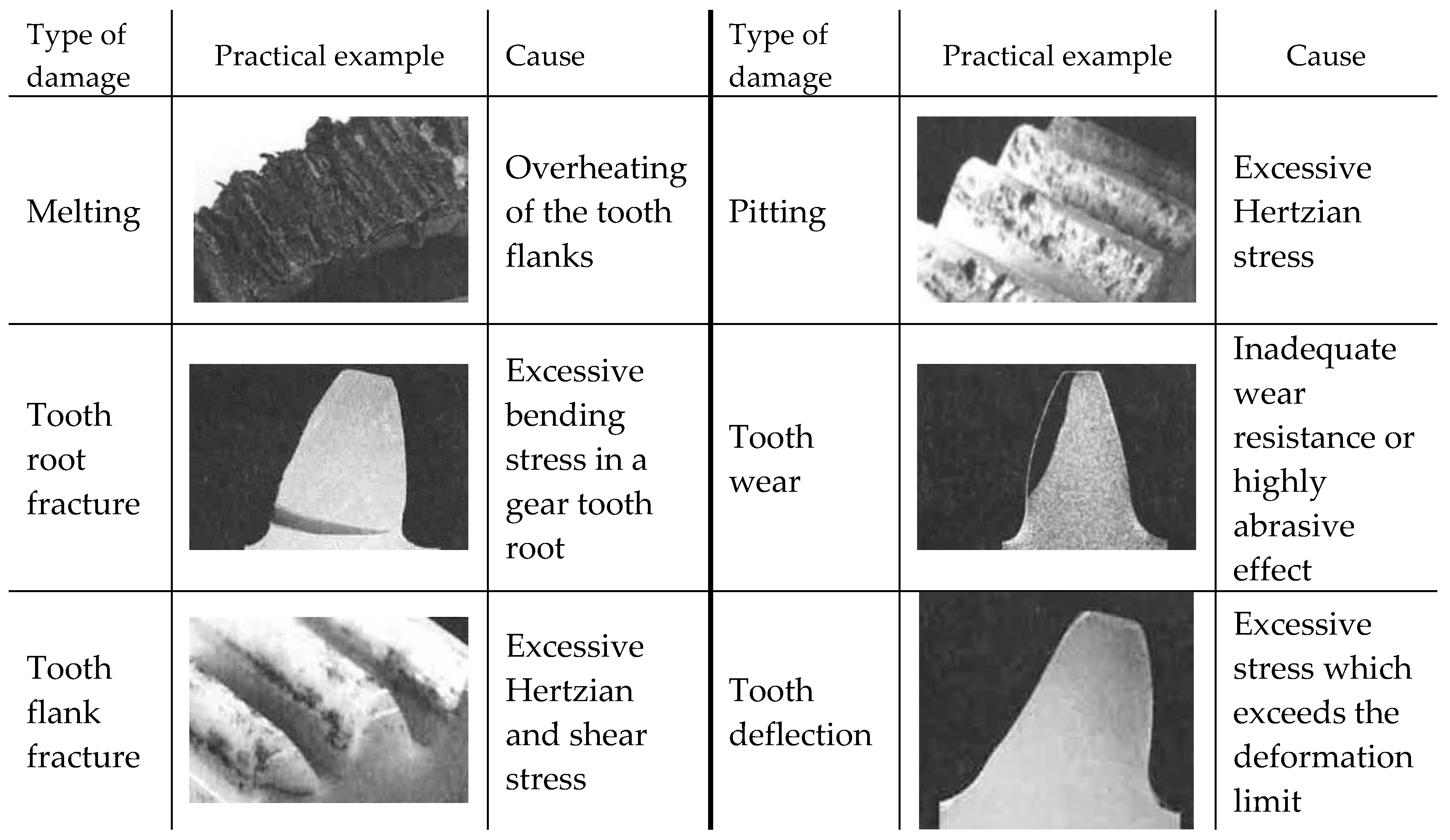
13]. Furthermore, the following failure types of polymer gears are addressed in [
14,
15,
16] and explained additionally in [
17,
18,
19]: melting, tooth root fracture, tooth flank fracture, pitting, tooth wear and tooth deflection (see
Figure 1). However, the proposed research focuses mainly on the tooth deflection of polymer gears which is a crucial parameter in respect to the proper gear drive operation. Namely, excessive tooth tip deflection can lead to serious disturbances of gear meshing and, consequently, increased noise and wear of the teeth flanks [
20,
21,
22].
Many researchers have recently investigated different types of polymer gears concerning tooth deflection using the appropriate computational approaches. Trobentar et al. [
23] investigated the gear tooth deflection of spur polymer gears made of POM. Their study determines the tooth deflection behaviour using the Young’s elastic material model and the hyperelastic Marlow model. The computational analyses have shown that the appropriate FE model (corresponding number of analysed gear teeth) significantly influences the correct stiffness of the analysed gear pair. The computational results also indicated that the appropriate non-linear material model should be considered, especially in the case of higher contact forces and, consequently, large deflections of gear teeth. The same authors investigated the influence of surface coatings on the tooth tip deflection of polymer gears [
24]. The obtained numerical results were then used to define approximate empirical equations for the calculation of gear tooth tip deflection for the coating material and the thickness of the surface coating layer. The results showed that the tooth tip deflection decreases with large values of the coating material Young’s modulus and with the coating layer thickness. Melick et al. [
25] investigated the load sharing and stresses in steel-plastic gear pairs, revealing significant deviations from conventional steel gear theories, which led to results similar to those of this study. Load sharing in steel-plastic pairs showed asymmetry around the pitch point due to tooth deformation, with the most severe loading occurring in the last part of the meshing cycle. Karimpour et al. [
26] proposed a computational model to analyse the meshing behaviour of polymer gears using Abaqus software. The numerical simulations showed that the kinematic behaviour of polymer gears is significantly different from those predicted by the classical metal gear theory. Namely, extensions to the path of contact occur at the beginning and end of the meshing cycle, which is caused by large tooth deflections of polymer gear teeth due to much lower stiffness values compared to metallic gears.
Many authors have also investigated the tooth deflection of polymer gears based on experiments, focusing on the development of new experimental methods. Herzog et al. [
27] tested cylindrical gears made of polybutylene terephthalate (PBT) under various loading torques using a newly developed experimental in situ system, which is capable of measuring tooth deformations. Their results showed that long-term gear tests under varying rotational speeds and loading lead to increasing wear and teeth deflection at higher speeds and torques. In further work [
28], the same authors tested a gear pair of steel/PBT at different rotational speeds and temperatures, focusing on measuring elastic tooth deflections. The experimental results that were obtained were then compared with VDI 2736 and Dynamomechanical Analysis (DMA). It was found that the measured tooth deflection at lower speeds was significantly lower than the calculated deformation according to VDI 2736 guidelines. On the other hand, Črne et al. [
29] used a gear pair of steel/POM-C in their research, comparing the DIC and EDD methods and verifying their adequacy using Finite Element Method (FEM).
In the framework of the presented study, a computational model for analysing the tooth deflection of polymer gears was developed and evaluated on the spur gear pair, where the pinion made of POM has meshed with a support gear made of steel. The computational analysis was divided into two steps. Firstly, a transient simulation was performed to identify the Highest Point of Single Tooth Contact (HPSTC), which represents the most critical engagement point regarding tooth deflection. In the next step, the numerical simulation was performed to obtain the tooth tip deflection.
2. Materials and Methods
2.1. Material and Geometry of Analysed Gear Pair
The developed computational model has been evaluated on the spur gear pair, where the pinion made of POM has meshed with a support gear made of steel [
30]. The basic geometrical and material parameters of the analysed gear pair are presented in
Table 1.
2.2. Determination of Tooth Deflection According to VDI 2736 Guidelines
The standardised procedure VDI 2736-2 [
11] applies to cylindrical polymer gears with reference profiles in accordance with DIN 867 [
31] and DIN 58400 [
32] as well as with modules
mn ≥ 0.1 mm. The calculation of load-carrying capacity is based on the Standard DIN 3990 [
33], which basically applies to metallic materials. In comparison with metals, polymers have a number of special features, such as (i) the dependence of their mechanical properties on operating temperature as well as on the level, time and speed of loading; (ii) their poorer thermal conductivity; and (iii) greater deformation. Considerable tooth deflection may occur, particularly with polymer gears with a narrow face width, such as those used in precision transmissions. This is due to their modulus of elasticity being much smaller than that of metals. It may take the form of pitch deviations, cause meshing impacts, and, among other things, increase noise. Furthermore, if the teeth of polymer gear have already been exposed for a relatively long time to a stationary load, the permissible tooth root stress could be exceeded due to the creep. In this respect, the deflection of the tooth tip should satisfy the following condition:
where
λ is the tooth tip deflection,
λp is the permissible tooth tip deflection,
Ft is the nominal tangential force,
b is the face width, β is the helix angle at the reference circle, and
E1 and
E2 are the moduli of elasticity of the pinion (1) and gear (2), respectively. A guide value for the permissible tooth tip deflection is:
where
mn is the normal module. If condition (2) is not satisfied (
λ > λ
P), running noise may increase and service life be reduced. At greater levels of tooth deflection, tip retraction may moderate the negative effects arising from deflection.
2.3. Computational Modelling
2.3.1. Geometry
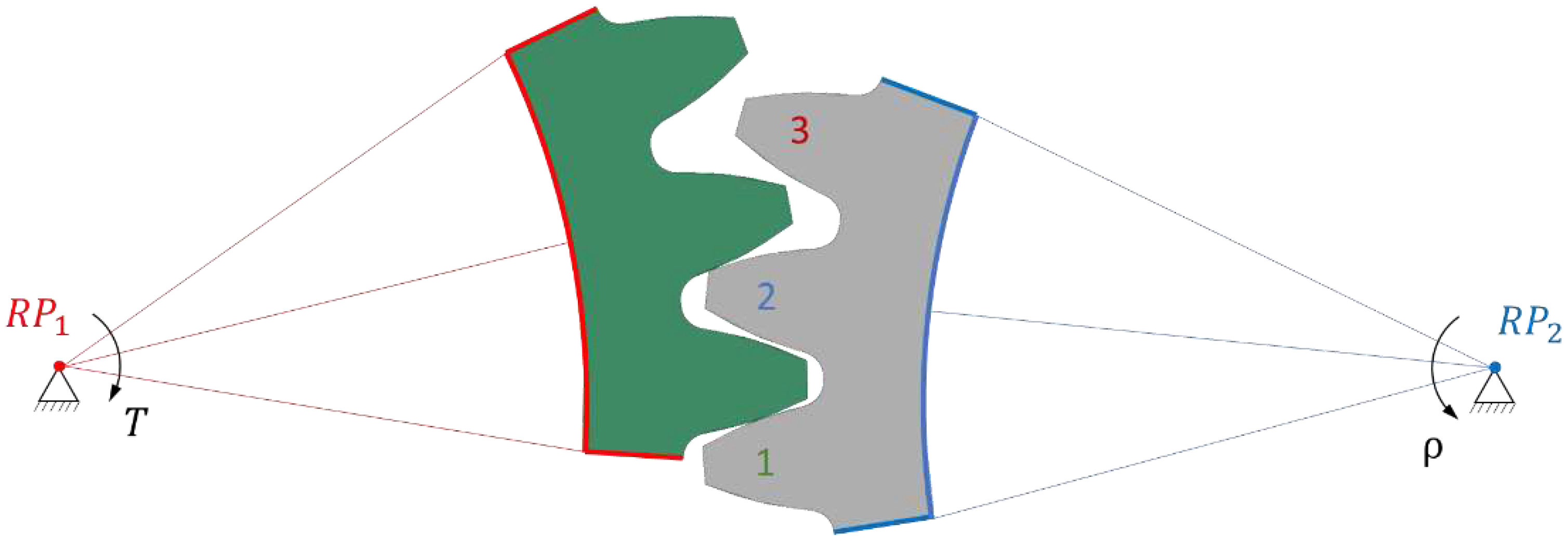
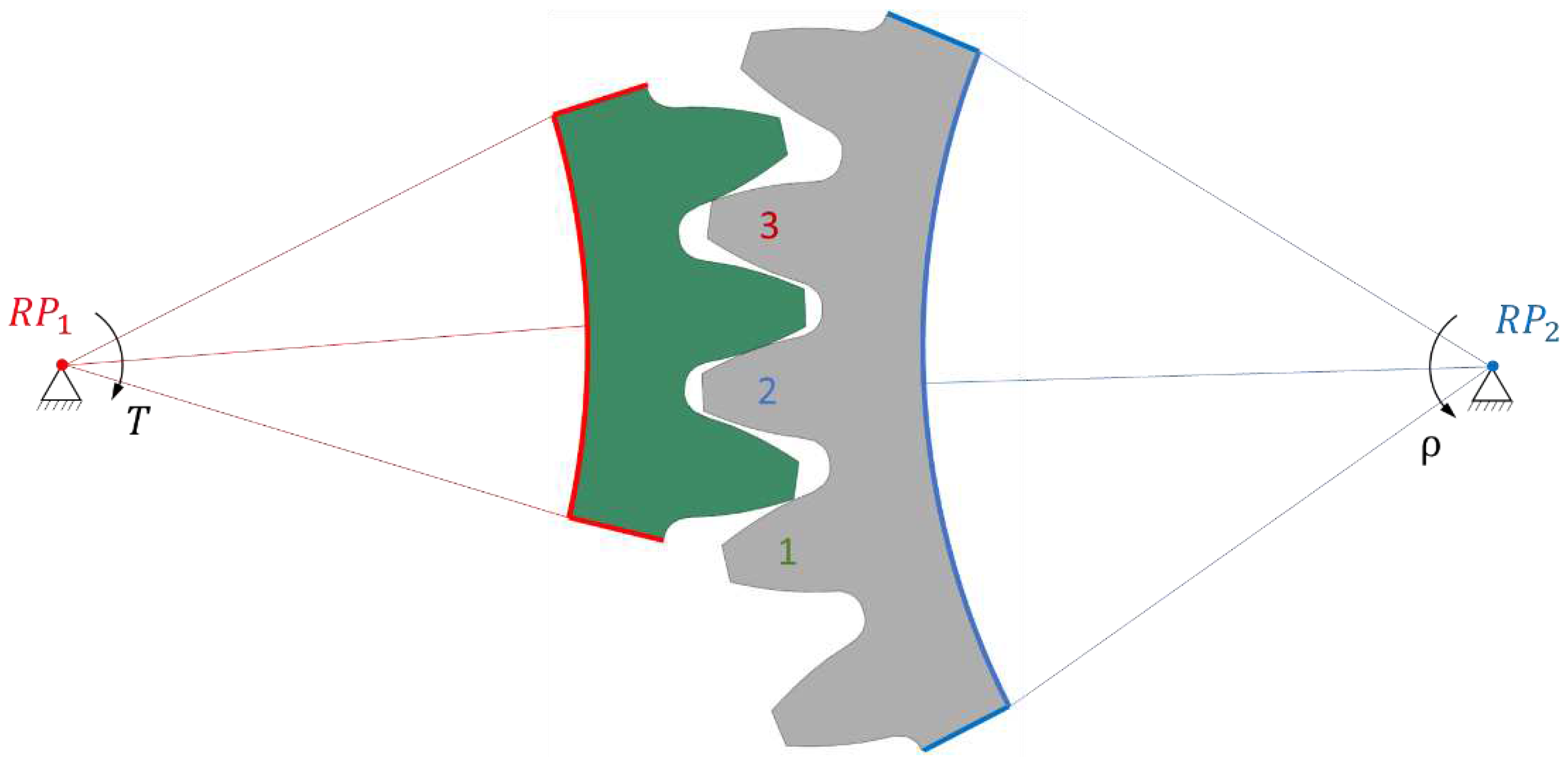
Because polymer gears have less stiffness compared to steel ones, we implemented a comprehensive analysis to determine the most suitable model. Our approach involved creating several 2D geometric models, each with its own characteristics. The first model (1/3) featured only one gear tooth and three pinion teeth (
Figure 2); the second model (3/3) included three gear teeth and three pinion teeth (
Figure 3), while the third model (3/5) comprised three gear teeth and five pinion teeth (
Figure 4).
2.3.2. Boundary Conditions
The boundary conditions were defined in remote points placed in the axis of the gears. The trimmed sides of the gear, marked in red, were rigidly connected to remote point RP1, allowing only rotation around the gear axis and the addition of a torque T = 16 Nm. On the other side, the trimmed sides of the pinion, marked in blue, were rigidly connected to remote point RP2, where they were fixed in all directions of the coordinate system. It is important to note that a rigid connection was used for linking remote points RP1 and RP2, as a deformable connection would cause the gear to deviate from the gear axis, leading to inaccurate results.
Frictional contact between the gear and pinion was defined with a coefficient of friction μ = 0.2, as given in VDI 2736 for dry (nonlubricated) contact of gear flanks. To specifically analyse the normal force on the gear tooth, frictionless contact conditions were employed. Material properties were assigned with linear elastic characteristics for the gear, while the pinion was characterised by hyperelastic properties using POM material.
2.3.3. Finite Element Mesh
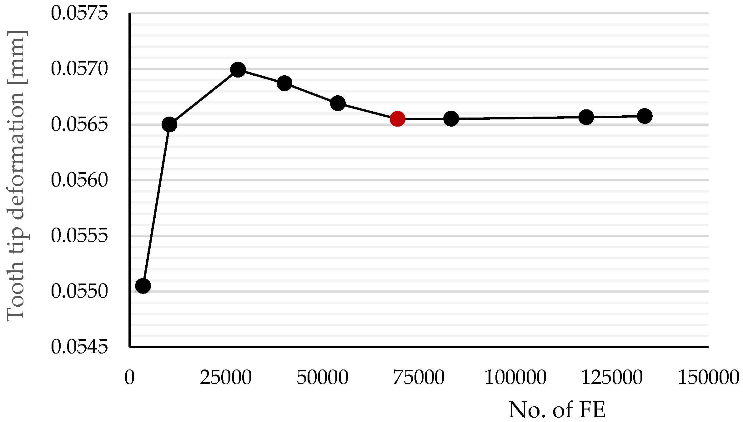
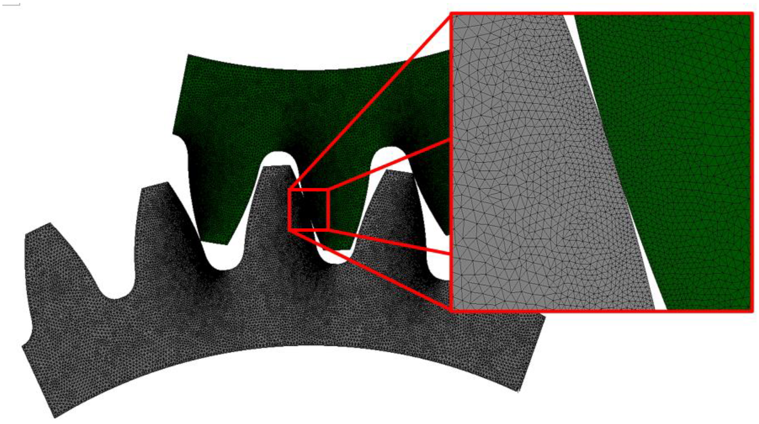
The finite element mesh was generated using triangular linear finite elements. A convergence analysis (see
Figure 5 for the mesh convergence analysis of 3/5 model) helped determine the optimal global element size of 0.1 mm and a local element size of 0.02 mm. The mesh was refined with the local size on the edges of tooth contacts (see
Figure 6 for 3/5 model ). The finite element mesh contained 69513 FE. A similar procedure has also been performed for models 1/3 and 3/3.
2.3.4. Numerical Simulation
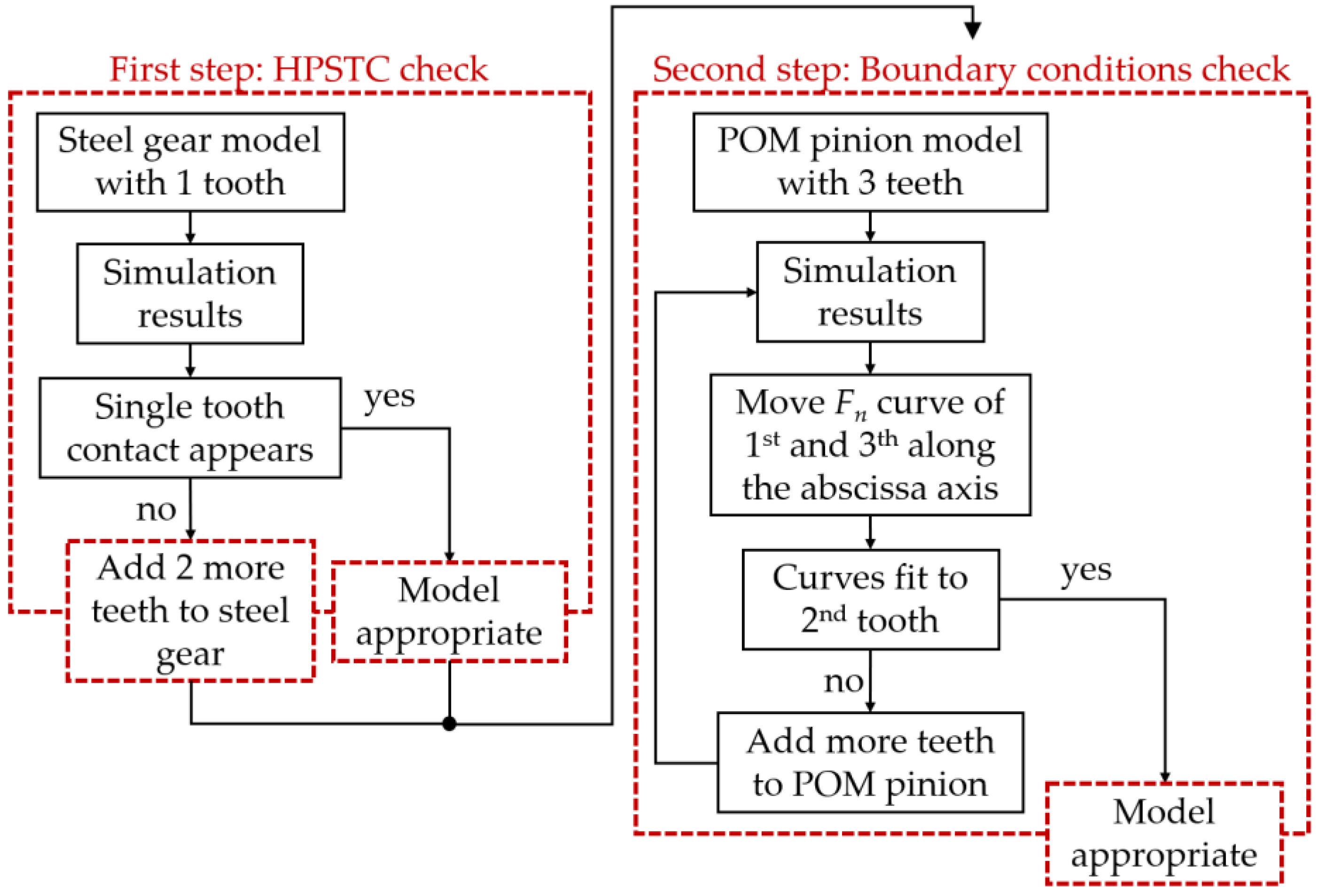
Due to the lower stiffness of polymer materials, a model relevance was checked (
Figure 7). This includes verifying whether the Highest Point of Single Tooth Contact (HPSTC) occurs or not and checking the appropriateness of the model simplification, as in polymer materials, loads are distributed over a larger area of the gear rather than just the meshing tooth [
25].
The analysis of normal forces on the gear tooth was performed in two steps. Firstly, a transient simulation was conducted, placing the gear at the start of contact (tip) of the second pinion tooth, followed by a rotation around RP
2 of 18°. Then, a static analysis was carried out, placing the gear in a position where the maximum force acted on the second pinion tooth, as shown in Figures 2 to 4. The numerical simulation was performed using the software package ANSYS version 2023 R1 [
34].
3. Results and Discussion
3.1 Model Comparison
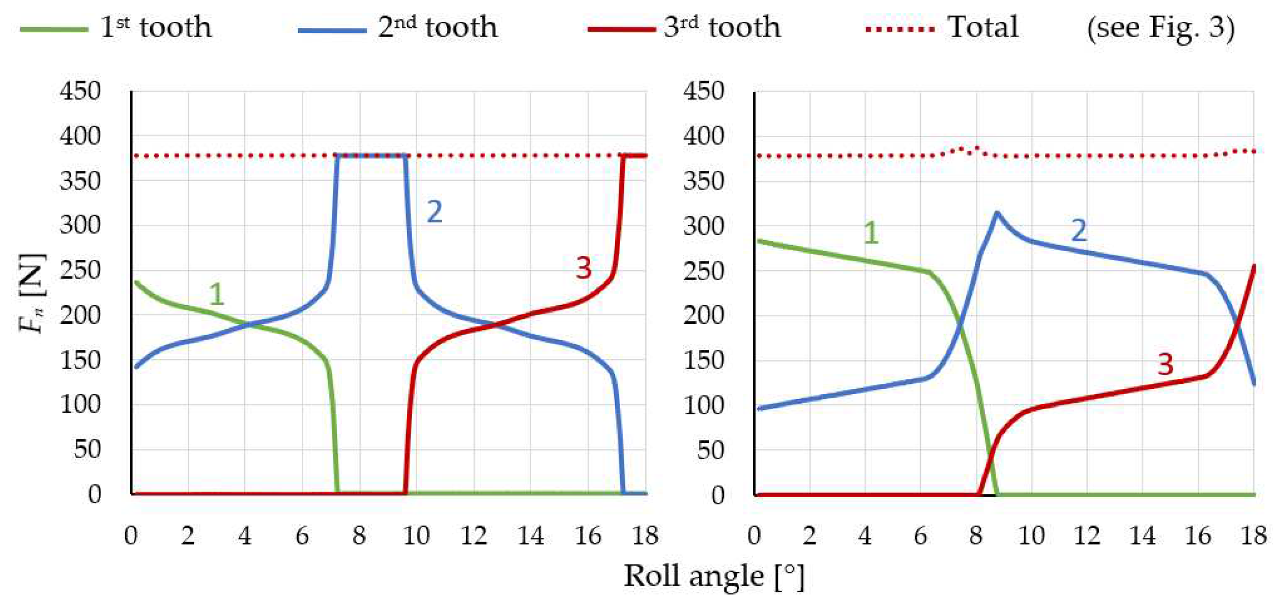
In the comparison between POM and a steel pinion, it is evident that a single gear tooth is insufficient. In the case of the POM pinion, the point of single tooth contact is never reached due to the deformation of neighbouring teeth over the pinion’s body, as opposed to what occurs in the case of steel pinion (
Figure 8). By applying the 3/3 and 3/5 models, it was observed that at the maximum force acting on the second (blue curve) tooth, the first (green curve) and third (red curve) tooth still remain in contact the whole time. This occurrence is a result of the entire pinion body deforming in the direction of the normal force due to the lower stiffness of POM.
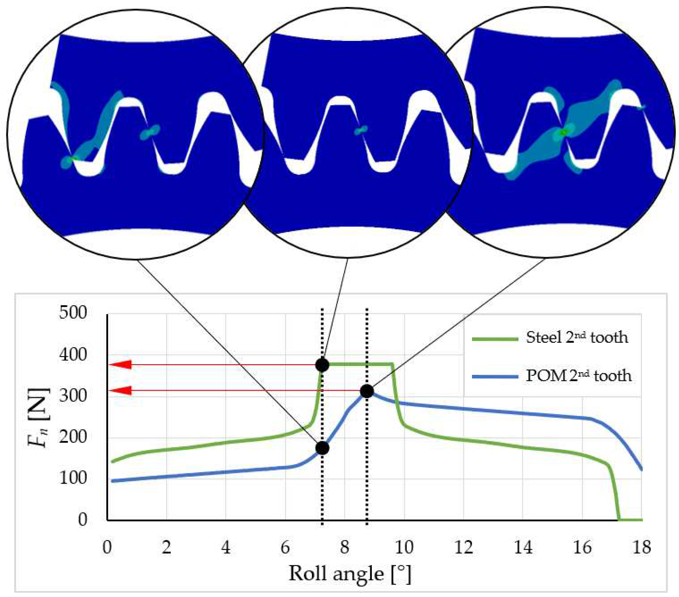
Figure 9 shows the difference between a steel pinion and a POM pinion. Compared to steel, POM has a lower maximum normal force, and, consequently, its location on the tooth flank is shifted closer to the root of the tooth. Similar findings were previously identified by [
25].
During the analysis of model relevance, the results were observed by varying the normal force on the pinion teeth while attempting to overlay curves by shifting them along the abscissa axis (roll angle) on the diagram, as shown in
Figure 10. In the 3/3 model, it was noticeable that the curves of the first and third teeth were shifted higher than the curve of the second tooth, indicating a higher reaction force on the pinion tooth. This suggests the irrelevance of the model since the force on all gear teeth during engagement should follow a similar pattern. The cause of these differences lies in the fixed boundary condition, which is too close to the first and third teeth, preventing actual deformation around the tooth. Adding two additional pinion teeth to the model on each side enables the deformation of a larger area around the loaded tooth. Therefore, the decision was made to use the 3/5 model, and its results are shown in
Figure 10 on the right, where the curves would perfectly fit if appropriately shifted along the abscissa axis as shown in
Figure 10 on the left. Adding additional teeth and the rest of the gears and pinion body resulted in negligible differences. The dotted curve in
Figure 10 represents the total reaction force on the pinion. At around 7.5° and 8.5° of POM roll angle, a peak appears on the curve, which leads to transmission error due to a force transfer from one tooth to another.
3.2. Comparison between Numerical and Analytical (VDI 2736) Results
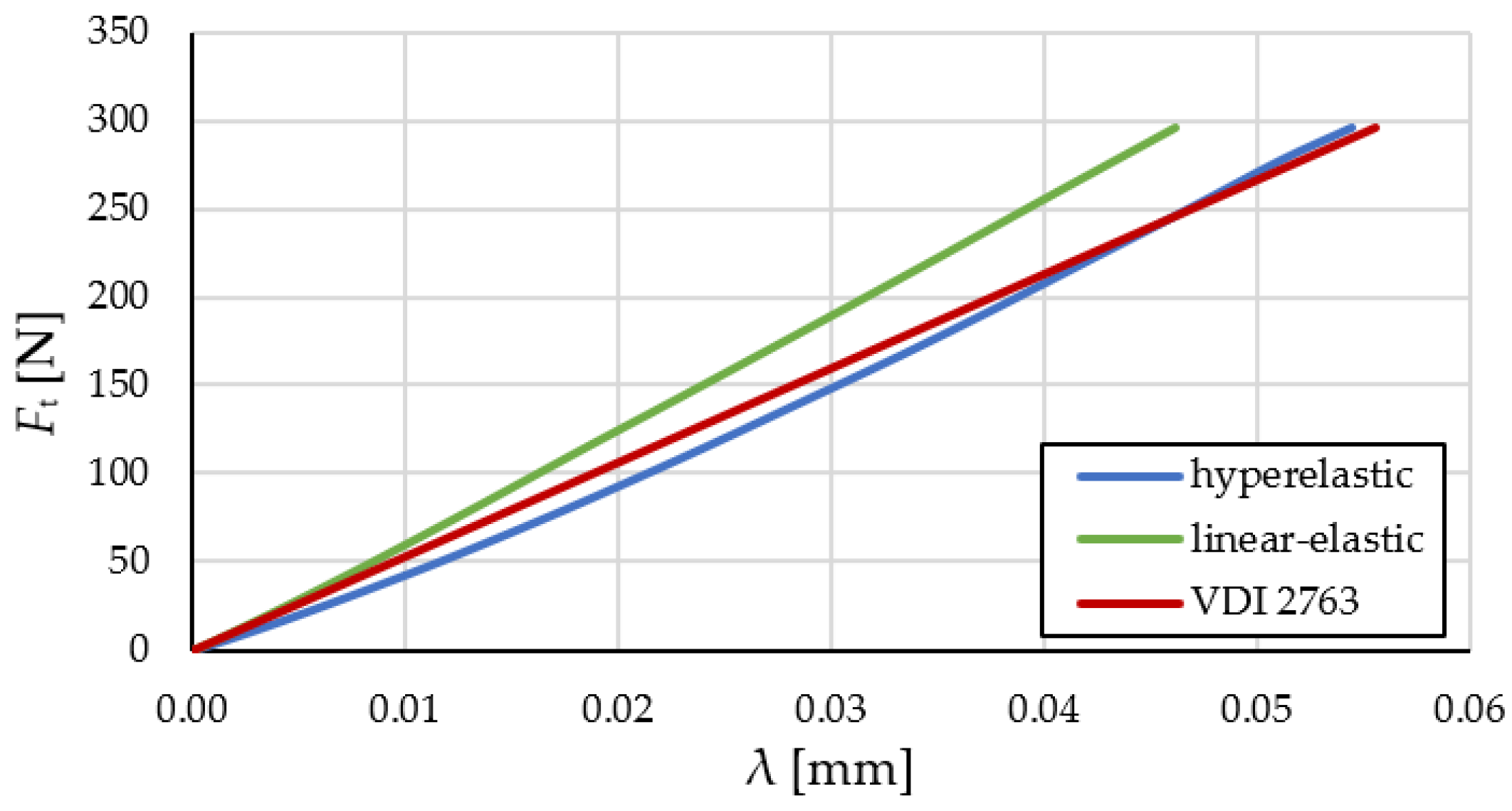
Figure 11 shows a comparison of the results from the 3/5 model with a linear-elastic material model and a hyperelastic material model, as well as calculations according to VDI 2736 guidelines. However, as previously determined, this model does not provide accurate results. The hyperelastic curve of the 3/5 model approaches the VDI 2736 curve, while the linear-elastic model 3/5 deviates from VDI 2736.
Based on the obtained computational results, it can be concluded that VDI 2736 serves as a good approximation for calculating the deformation of the polymer gear tooth but not along the entire engagement line and the magnitude of the external loading (i.e. torque). Due to the consideration of the hyperelastic model, the deviation of the curve increases at lower loads.
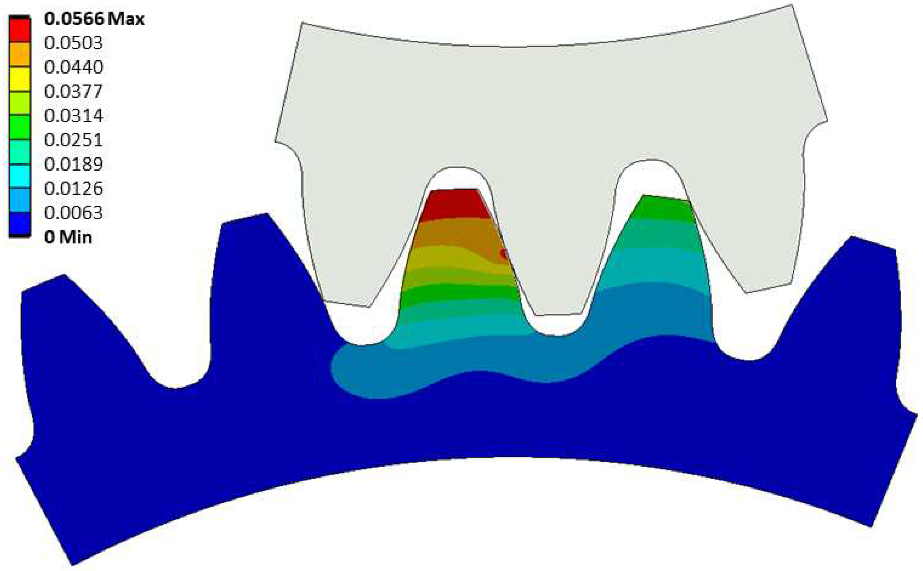
The maximum tooth deflection at the highest point of the tangential force on the second tooth occurs at the tip of the tooth and measures 0.057 mm (
Figure 12). Through the static analysis, it was observed that the gear deforms the second and third pinion teeth, while the first tooth deviates from contact with the gear due to the deformation of a larger area of the pinion body.
4. Conclusions
The presented study proposes a computational model to analyse the tooth deflection of polymer gears. It was shown that an incorrectly defined numerical model for polymer gear pair results in entirely inaccurate results, emphasising the need to carefully examine the dynamic behaviour of gears. In this case, the use of a model where only one gear tooth meshes with the pinion is irrelevant. Unlike stiffer materials, in the case of pinion made of POM, a single contact point never occurs due to deformation with such geometry. Not only the tooth is deformed, but also part of the pinion body, which causes it to deform and “drag along” neighbouring teeth. Consequently, a smaller normal force on a single tooth can be obtained, and the point of the highest maximal normal force moves closer to the tooth root, which leads to asymmetric tooth meshing.
The relevance of the numerical model can be determined by comparing the reaction forces on each individual tooth. Since the tooth meshing cycle occurs in a consistent cyclic pattern, the reaction forces should be equal on each tooth of the gear. Therefore, by aligning the curves of the reaction force with respect to the gear rotation angle in a properly designed numerical model, we achieve a perfect overlap. This implies that the reaction forces on the gear are equal at every point on all teeth.
The main purpose of the work was to create a suitable computational model comparable to the calculation based on VDI 2736 guidelines. Here, the numerical results showed more accurate results due to the hyperelastic material characteristics of POM. VDI 2736 calculation showed the comparability with numerical results with a slightly larger deviation at lower loads. Despite this, VDI 2736 guidelines serves as a appropriate calculation approach to check the tooth deflection of polymer gears.
Author Contributions
Conceptualisation, S.G. and J. K.; methodology, S.G. and J.K.; software, A.I.; validation, S.G.; formal analysis, A.I.; investigation, A.I.; writing—original draft preparation, A.I and S.G.; writing—review and editing, all authors; visualisation, A.I.; supervision, S.G.; project administration, S.G.; funding acquisition, S.G. All authors have read and agreed to the published version of the manuscript.
Funding
This research was funded by the Slovenian Research Agency (ARIS), Research Core Funding No. P2-0063.
Data Availability Statement
The data presented in this study are available on request from the corresponding author.
Acknowledgments
The authors acknowledge the financial support of the Research Core Funding (No. P2-0063) from the Slovenian Research Agency.
Conflicts of Interest
The authors declare no conflict of interest.
References
- Muratović, E.; Muminović, A.; Delić, M.; Pervan, N.; Muminović, A.J.; Šarić, I. Potential and Design Parameters of Polyvinylidene Fluoride in Gear Applications. Polymers (Basel). 2023, 15, 4275. [Google Scholar] [CrossRef] [PubMed]
- Polanec, B.; Glodež, S.; Belšak, A. Noise Evaluation of Coated Polymer Gears. Polymers (Basel). 2023, 15, 783. [Google Scholar] [CrossRef]
- Trobentar, B.; Hriberšek, M.; Kulovec, S.; Glodež, S.; Belšak, A. Noise Evaluation of S-Polymer Gears. Polymers (Basel). 2022, 14, 438. [Google Scholar] [CrossRef] [PubMed]
- Miler, D.; Hoić, M.; Domitran, Z.; Žeželj, D. Prediction of Friction Coefficient in Dry-Lubricated Polyoxymethylene Spur Gear Pairs. Mech. Mach. Theory 2019, 138, 205–222. [Google Scholar] [CrossRef]
- Evans, S.M.; Keogh, P.S. Wear Mechanisms in Polyoxymethylene Spur Gears. Wear 2019, 428–429, 356–365. [Google Scholar] [CrossRef]
- Zhong, B.; Zhang, R.; Wei, P.; Liu, H.; Li, J.; Lu, Z. The Durability Performance of Polyketone Gears under Various Lubrication Conditions. J. Tribol. 2022, 144. [Google Scholar] [CrossRef]
- Pogačnik, A.; Tavčar, J. An Accelerated Multilevel Test and Design Procedure for Polymer Gears. Mater. Des. 2015, 65, 961–973. [Google Scholar] [CrossRef]
- TAVČAR, J.; GRKMAN, G.; DUHOVNIK, J. Accelerated Lifetime Testing of Reinforced Polymer Gears. J. Adv. Mech. Des. Syst. Manuf. 2018, 12, JAMDSM0006–JAMDSM0006. [Google Scholar] [CrossRef]
- Alharbi, K.A.M. Wear and Mechanical Contact Behavior of Polymer Gears. J. Tribol. 2019, 141. [Google Scholar] [CrossRef]
-
VDI 2736 Part 1 Thermoplastic Gear Wheels—Materials, Material Selection, Producton Methods, Production Tolerances, Form Design; Verein Deutscher Ingenieure: Harzgerode, Germany, 2016.
- VDI 2736 Part 2 Thermoplastic Gear Wheels—Cylindrical Gears—Calculation of the Load—Carrying Capacity.; Verein Deutscher Ingenieure: Harzgerode, Germany, 2016.
-
VDI 2736 Part 3 Thermoplastic Gear Wheels—Crossed Helical Gears—Mating Cylindrical Worm with Helical Gear—Calculation of the Load Carrying Capacity; Verein Deutscher Ingenieure: Harzgerode, Germany, 2016.
-
VDI 2736 Part 4 Thermoplastic Gear Wheels—Determination of Strength Parameters on Gears; Verein Deutscher Ingenieure: Harzgerode, Germany, 2016.
- Zorko, D.; Kulovec, S.; Duhovnik, J.; Tavčar, J. Durability and Design Parameters of a Steel/PEEK Gear Pair. Mech. Mach. Theory 2019, 140. [Google Scholar] [CrossRef]
- Senthilvelan, S.; Gnanamoorthy, R. Damage Mechanisms in Injection Molded Unreinforced, Glass and Carbon Reinforced Nylon 66 Spur Gears. Appl. Compos. Mater. 2004, 11, 377–397. [Google Scholar] [CrossRef]
- Bravo, A.; Koffi, D.; Toubal, L.; Erchiqui, F. Life and Damage Mode Modeling Applied to Plastic Gears. Eng. Fail. Anal. 2015, 58, 113–133. [Google Scholar] [CrossRef]
- Singh, A.K.; Siddhartha; Singh, P.K. Polymer Spur Gears Behaviors under Different Loading Conditions: A Review. Proc. Inst. Mech. Eng. Part J J. Eng. Tribol. 2018, 232.
- Sarita, B.; Senthilvelan, S. Effects of Lubricant on the Surface Durability of an Injection Molded Polyamide 66 Spur Gear Paired with a Steel Gear. Tribol. Int. 2019, 137, 193–211. [Google Scholar] [CrossRef]
- Singh, P.K.; Siddhartha; Singh, A.K. An Investigation on the Thermal and Wear Behavior of Polymer Based Spur Gears. Tribol. Int. 2018, 118, 264–272. [CrossRef]
- Hochrein, J.-F.; Otto, M.; Stahl, K. Fast Tooth Deflection Calculation Method and Its Validation. Forsch. im Ingenieurwes. 2022, 86, 845–859. [Google Scholar] [CrossRef]
- Mao, K.; Greenwood, D.; Ramakrishnan, R.; Goodship, V.; Shrouti, C.; Chetwynd, D.; Langlois+, P. The Wear Resistance Improvement of Fibre Reinforced Polymer Composite Gears. Wear 2019, 426–427, 1033–1039. [Google Scholar] [CrossRef]
- Mao, K.; Chetwynd, D.G.; Millson, M. A New Method for Testing Polymer Gear Wear Rate and Performance. Polym. Test. 2020, 82, 106323. [Google Scholar] [CrossRef]
- Trobentar, B.; Glodež, S.; Zafošnik, B. Gear Tooth Deflection of Spur Polymer Gears. In International Gear Conference 2014: 26th–28th August 2014, Lyon; Elsevier, 2014; pp. 129–137.
- Trobentar, B.; Glodež, S.; Flašker, J.; Zafošnik, B. The Influence of Surface Coatings on the Tooth Tip Deflection of Polymer Gears. Mater. Tehnol. 2016, 50. [Google Scholar] [CrossRef]
- Melick, H.G.H. Tooth Bending Effects in Plastic Spur Gears. Gear Technol. 2007, 58–66. [Google Scholar]
- Karimpour, M.; Dearn, K.D.; Walton, D. A Kinematic Analysis of Meshing Polymer Gear Teeth. Proc. Inst. Mech. Eng. Part L J. Mater. Des. Appl. 2010, 224, 101–115. [Google Scholar] [CrossRef]
- Herzog, C.; Wolf, M.; Schubert, D.; Drummer, D. In Situ Investigation of the Influence of Varying Load Conditions on Tooth Deformation and Wear of Polymer Gears. Forsch. im Ingenieurwes. 2022, 86, 545–555. [Google Scholar] [CrossRef]
- Herzog, C.; Drummer, D. Limitations of the Check Calculation for Tooth Deformation of Plastic Gears According to Gear Design Guideline VDI 2736. Polymers (Basel). 2023, 15, 3809. [Google Scholar] [CrossRef] [PubMed]
- Černe, B.; Petkovšek, M. High-Speed Camera-Based Optical Measurement Methods for in-Mesh Tooth Deflection Analysis of Thermoplastic Spur Gears. Mater. Des. 2022, 223, 111184. [Google Scholar] [CrossRef]
- Bončina, T.; Polanec, B.; Zupanič, F.; Glodež, S. Wear Behaviour of Multilayer Al-PVD-Coated Polymer Gears. Polymers (Basel). 2022, 14, 4751. [Google Scholar] [CrossRef] [PubMed]
- DIN 867 Basic Rack Tooth Profiles for Involute Teeth of Cylindrical Gears for General Engineering and Heavy Engineering; German guidelines, Beuth Verlag, 1986.
- DIN 58400 Basic Rack for Involute Teeth of Cylindrical Gears for Fine Mechanics; German guidelines, Beuth Verlag, 1984.
- DIN 3990 Calculation of Load Capacity of Cylindrical Gears, German Standard; Beuth Verlag, 1987.
- Ansys 2023 R1 Engineering Simulation Software 2023.
|
Disclaimer/Publisher’s Note: The statements, opinions and data contained in all publications are solely those of the individual author(s) and contributor(s) and not of MDPI and/or the editor(s). MDPI and/or the editor(s) disclaim responsibility for any injury to people or property resulting from any ideas, methods, instructions or products referred to in the content. |
© 2024 by the authors. Licensee MDPI, Basel, Switzerland. This article is an open access article distributed under the terms and conditions of the Creative Commons Attribution (CC BY) license (http://creativecommons.org/licenses/by/4.0/).
