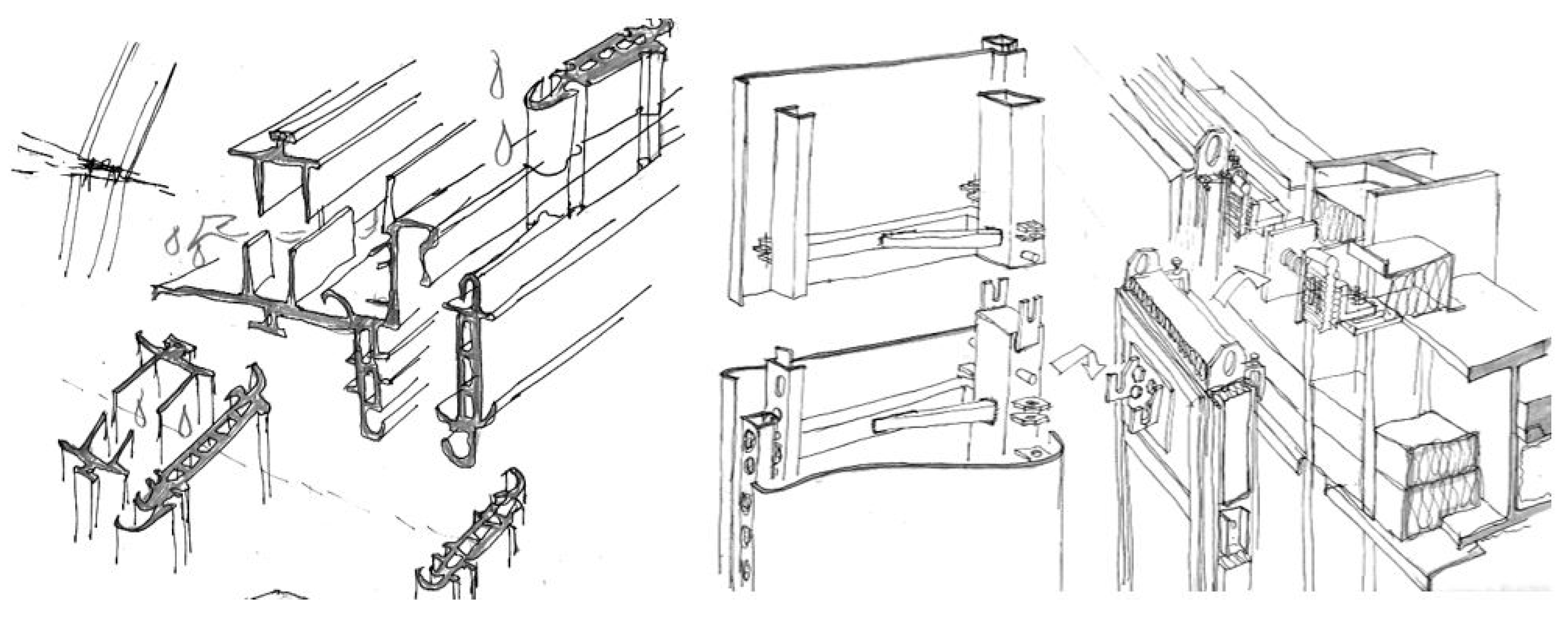
1. Introduction
Constant innovation is the result of the architects combining systems and materials to the possible limit to demonstrate their creativity. These ideas are generally communicated through the generation of images as the graphic expression of future works. This is the first approximation to the feasible, and the result is increasingly committing because of the relationship between expectations and realities in buildings.
Photo-realistic images are used as an expression of future realities [
1], enabling programs to significantly represent features such as geometries, colours, textures, transparency, light, and brightness. However, the credibility of the results and real feasibility of the proposals presented in such graphic expression systems are uncertain. These systems are usually based on the results of previous experiences taken as a reference but do not replace the most practical part of the process of creating unique façades, resulting in proposals of high formal risk and complicated technical solutions [
2]. Notably, in the design process, everything is feasible. However, it must be performed technologically, a phase that does not appear until the proposed façade is developed. Notably, images that are not supervised by construction specialists can be misleading, as they may simply be designed to present ideas, without considering the key factors of the materialisation.
The drawn architecture should preserve its constructive reasoning, as the realisation of a potential idea requires suitable mechanisms. This implies the design and treatment of façades as the external images of buildings, demonstrating their significant influence and the perception of the building, proposing singular façades with unique and original designs via technological innovation and using new materials with the conviction that it will be solved constructively [
3].
Generally, this façade is developed via a brainwave idea, which is a sudden illumination that highlights some details that may not be noticed in many cases in the approach to the problem nor may not easily be deducible from it, as an example of creativity on the part of the individual.
The brainwave defines the construction innovation that highlights details by simplification rather than sophistication and has thus become the key element of façade construction details. Therefore, each case study has its brainwave that highlights details through construction simplicity. However, some iconic buildings require sophistication and high technological improvement [
4]. For example, the Apple store in New York aims to exceed construction limits, demonstrating continuous technical innovation and design care research. Generally, a unique design feature is connected with an innovative façade that should be resolved with technical complexity and high-tech solutions. Nevertheless, in some cases, the virtue lies in simple solutions used suitably. This involves real progress in architectural innovation and is a result of conventional optimization solutions. Therefore, the basic knowledge of the construction techniques is decisive for the progress.
2. Case Studies
The analysis of the case studies aims to verify if, despite the innovative images that façade projects have, the buildings can be resolved with standard construction systems adapted to each situation. Therefore, five case study projects were selected in which the authors of the paper have participated as façade consultants. We aim to accomplish a constructive analysis of the façade and discover the brainwave idea of each project.
Agbar Tower. 2004. Barcelona. Jean Nouvel + B720
Porta Fira Tower. 2010. Barcelona. Toyo Ito + B720
La Querola. In progress. Andorra. Jean Nouvel + B720
Isla Blanca. 2023. Ibiza. Alain Moatti + Josep Ferrer Ll.
Mohamed VI Tower. In progress. Rabat. Rafael de la Hoz
2.1. Agbar Tower, Barcelona. Jean Nouvel + B720. 2004
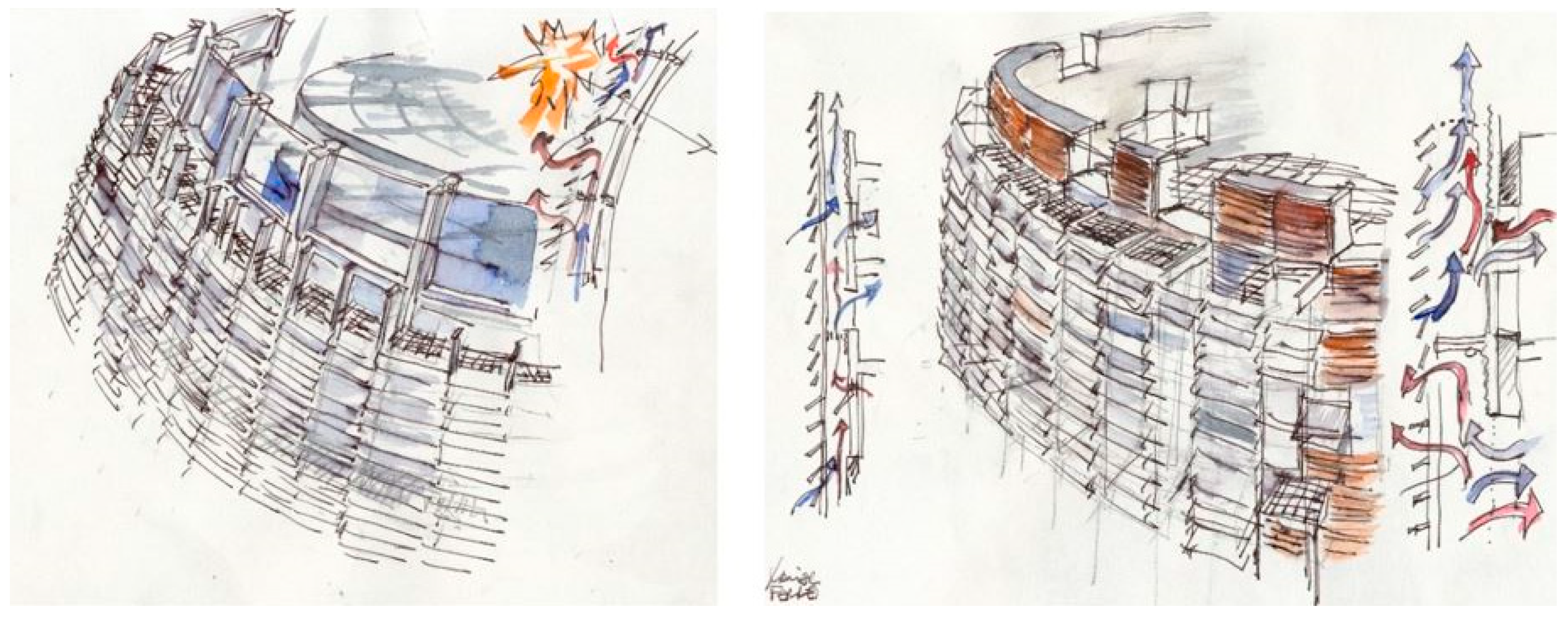
The Agbar Tower, located in Barcelona, is a singular 34-floor office building with a height of 115 m. The façade is designed as a double skin enclosure to exhibit the following flexibility and performance: energetic and light control, natural ventilation, high acoustic mitigation, different orientation, and necessity suitability. Moreover, a homogeneous was achieved as the architect wanted to obtain the same appearance. The interior skin façade is conceived using two different construction systems: the shaft, built with a conventional ventilated façade and windows, and the dome, developed as a curtain wall (
Figure 1). Additionally, the exterior skin is continuous in all the envelope surface, thus unifying the exterior image of the tower.
The shaft contains an edge concrete lead-bearing wall with small square holes, inspired by fractal rules, which indicates where to incorporate standard windows in lacquered aluminium carpentry and double glazing (
Figure 2). The wall consists of a superposed ventilated façade comprising a rock wool panel insulation containing 80-mm ventilated chamber corrugated aluminium sheets, which are curved and thermos-coated in 45 different colours. The structural system is completely modified in the dome, shifting the concrete load-bearing wall to a steel profile structure generating a colossal dimension mesh. This structural modification enables the creation of a glazed dome, constructed with a standard modular curtain wall that can be easily adapted to the double curvature polygonal form. The glass in the modular curtain wall is a double-glazing screen painted blue with blue layers inserted.
In all the tower enclosures, the exterior skin façade is built in glass slat continuous skins to unify the two construction systems used in the interior skin. The slats are made of security laminated glass with different compositions by combining serigraph, printing, extra light lass, and conventional glass based on the required project and distributed following geographic orientation, interior views, or inclination in the dome. The 52.000 installed glass slats are supported by aluminium brackets, which are placed 90 cm away from the interior façade, thus generating an air cavity that improves the global performance of the façade and enables the integration of the catwalk for maintenance.
The glass slat system support for the double skin façade is considered the brainwave idea of the project, as the key element that enables obtaining the desired images and performances (
Figure 3). A conventional system inherited from the traditional kitchen windows in Barcelona houses has technically been developed and thus can be used in one of the most emblematic buildings in Barcelona. This project realized an aluminium bracket that can be regulated in different positions.
The systems consist of 52.000 glass salts of 100 30 cm dimension laminated glass supported by two aluminium profiles in the short sides, glued with structural silicone, fixed to the vertical profiles with plates that enable different angle positions based on diverse requirements and disposed of in assorted combinations of inclination, colour, and serigraphy percentages. The solution offers a continuous layer that adapts to the tower shape.
2.2. Porta Fira Tower, Barcelona. Toyo Ito + B720. 2010.
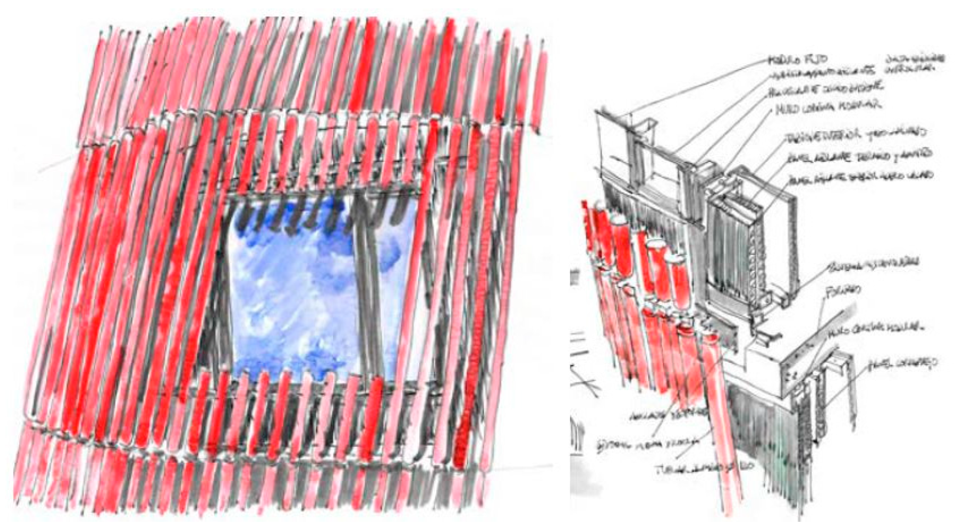
The Porta Fira Hotel Tower located in Barcelona is set out with a floor that turns on itself, rotates as it rises, and is translated on its vertical axis from a specific height simultaneously. Finally, it opens like a vegetable shape. Because of the complex geometric composition of the building, the façade is designed with two different skins, enabling each skin to satisfy specific requirements. First, the interior façade consists of a modular curtain wall light system with aluminium profiles and double glazing in the vision areas and opaque panels conceived to guarantee acoustic, thermal, fire protection, and water tightness requirements. The modular curtain wall is disposed between the slabs, thus horizontal profiles are indispensable to realize a tight joint in the system. The vision area casement window is used both for ventilation and cleaning of the glass. An aluminium panel sandwich addresses the opaque areas, formed by a lacquered aluminium sheet, thermal insulation, and galvanised steel sheet in the interior (
Figure 4). To improve the fire protection, acoustic, and thermal insulation performances, the sandwich panel rock wool or fibro silicate boards are installed in inside, following specific requirements in each floor.
Second, the exterior façade is outlined as an enclosure to award texture and shape to the tower. The skin comprises independent 1.00 red aluminium tubes fastened on the ends with swivel joints to enable the desired twisting from the floor to the crown of the building (
Figure 5). This tubular skin functions as a solar protection element as it reduces 50
of direct solar radiation in the inner skin. The assembly site is built without auxiliary tools in the exterior oblique to first assemble the exterior red aluminium tube skins from the inside followed by the interior vertical enclosure. Owing to the light weight of the modules, they can be positioned from the inside without additional machinery.
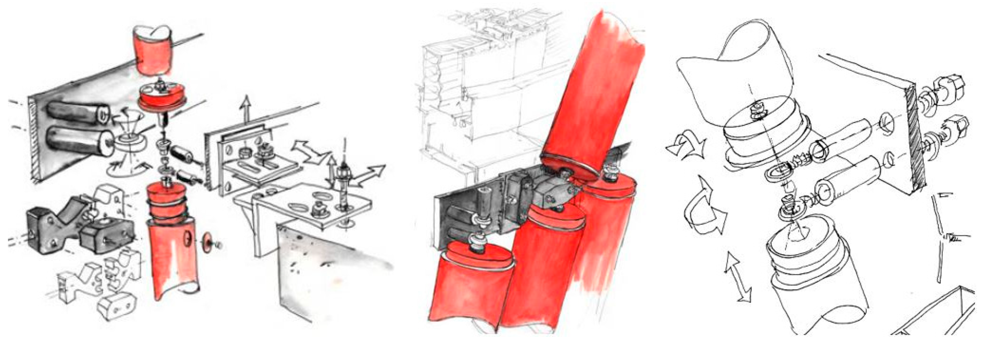
The brainwave that enables the development of the facade outer shell in the project is the round swivel that forms part of the fixation system of the tube lattice (
Figure 6). A custom element in the car industry is adapted to be used in the façade construction system, enabling the free displacement and combination of different angles (that are not repeated in any situation all over double skin façades). At the end of the red aluminium tubes is disposed of a turned polyethylene bit to facilitate the joint between the tube and swivel joint, obtaining an articulation in both tubes ends to enable the adaptation to the main shape of the building.
2.3. La Querola, Andorra. Jean Nouvel + J.Ribas. In progress.
La Querola from Ordino is a residential complex comprising a seven-building assembly, adjoined to the mountain. The building façade design can reproduce a natural element on an increased scale, aiming to address the definition of ‘
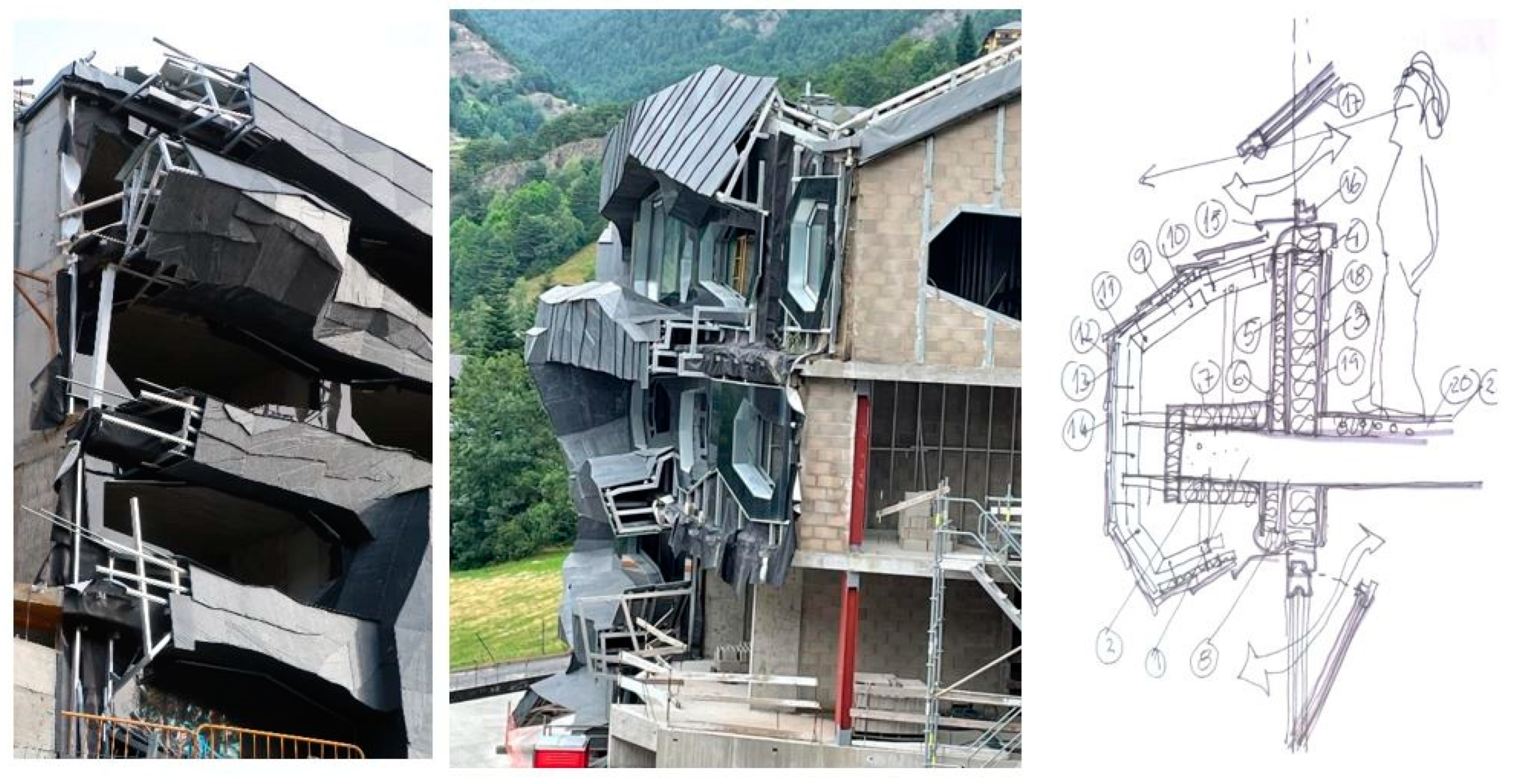
querol’: a geological accident formed in a flat landscape where it emerges an enormous stone with stratified layers. A dry joint construction system was proposed to construct the cavity-ventilated wall façade of the project. Therefore, the cladding could adapt to the building shapes with the required tolerance and flexibility. The exterior cladding executed in natural stone is variable in different levels and sections generating unequal planes with irregular folds. Furthermore, the windows have irregular and variable shapes and large dimensions, leading to difficulty in realising a type detail. A steel tube grid filled with concrete blocks in the interior enclosure was selected (
Figure 7), enabling substructural integration in the vertical plane of the tipping windows and supporting the exterior ribs ensemble, where the exterior stone cladding is fixed. The same system used in the façade is applied to the roof, as the enclosure is continuous.
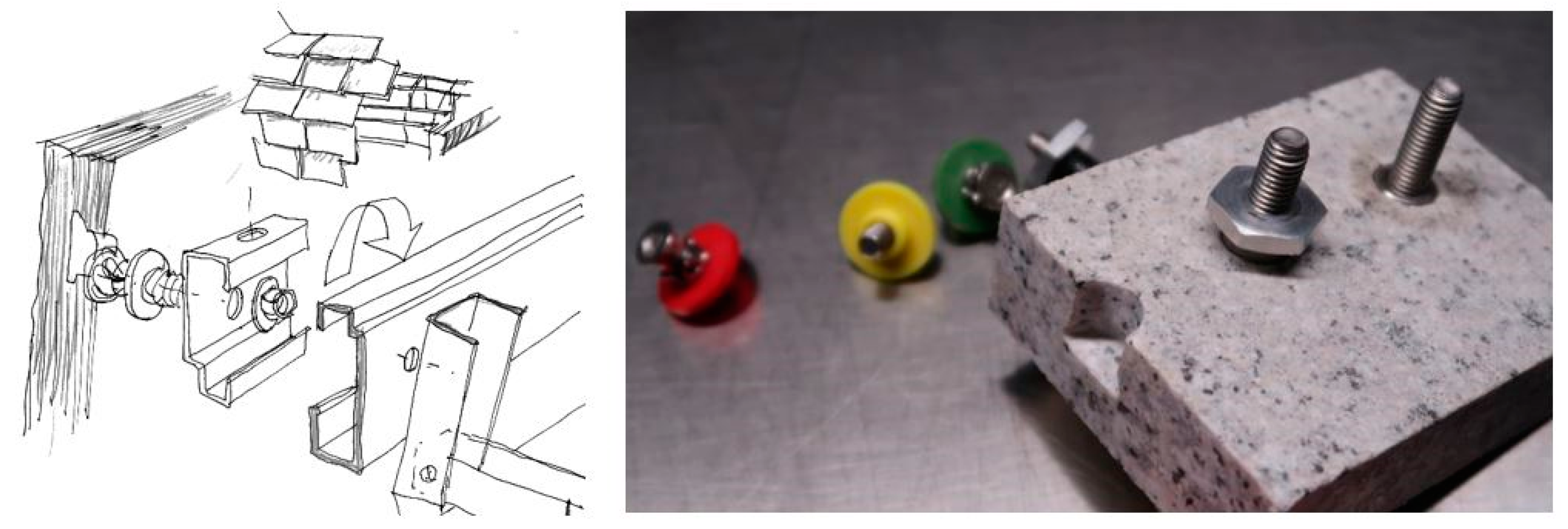
The brainwave idea in this project is as simple as the slat cladding fixation system, (
Figure 8) which was developed in the prototype execution phase. Initially, the idea was to be applied in hole fixations. However, as shown in the prototype, the system has limitations in the execution of the façade. A loading test was conducted to determine the viability of the concealed fixing embedded in a slate piece. Thus, previously discovered problems were prevented. A single fixing element used with another cladding type of materials was tested, and its performance with slate materials, which are usually fixed via hole fixations or supporting components, was verified.
2.4. Isla Blanca, Ibiza. Alain Moatti + Josep Ferrer Ll. 2023
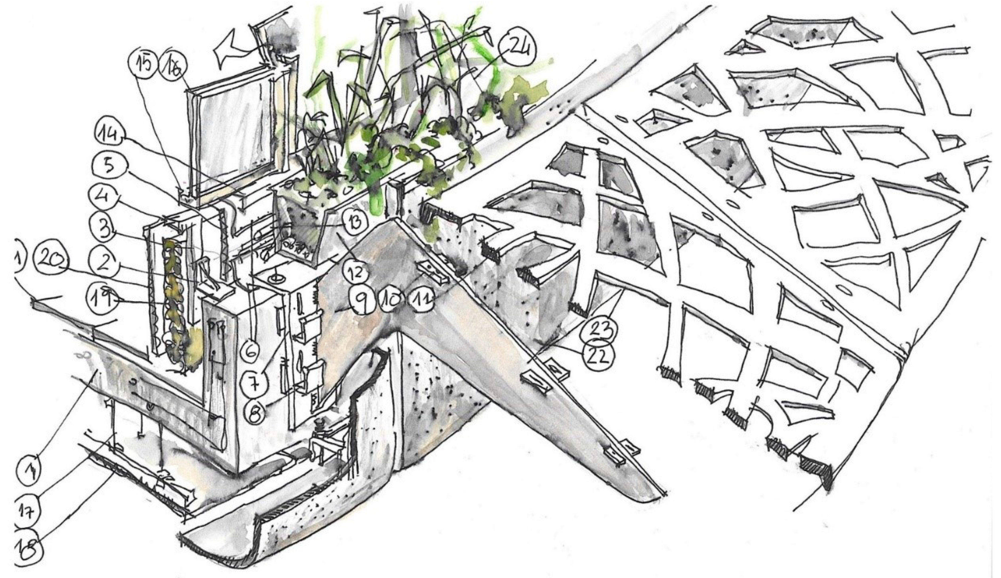
The Isla Blanca building located on Ibiza Island is a commercial and luxury housing complex. Its façade consists of two distinguishable parts: a commercial façade, which aims to be as transparent as possible, and the housing area comprising all height windows, terraces with jardinières, and solar protection termed ‘voilettes’. All the façade components have to be adapted to the floor geometry: windows, partitions, ventilated façade, jardinières, and eaves. The opaque façade coinciding with the slab edge and the handrail are resolved with white and smooth texture ultra-high performance fibre reinforced concrete (UHPFRC) prefabricates panels. Between the joints of the panels, the cantilever elements enable the fixation of the solar protection eaves or ‘
voilettes’ (
Figure 9). The glazed façade is built with all high windows adapted to the curved geometry by polygonal lines.
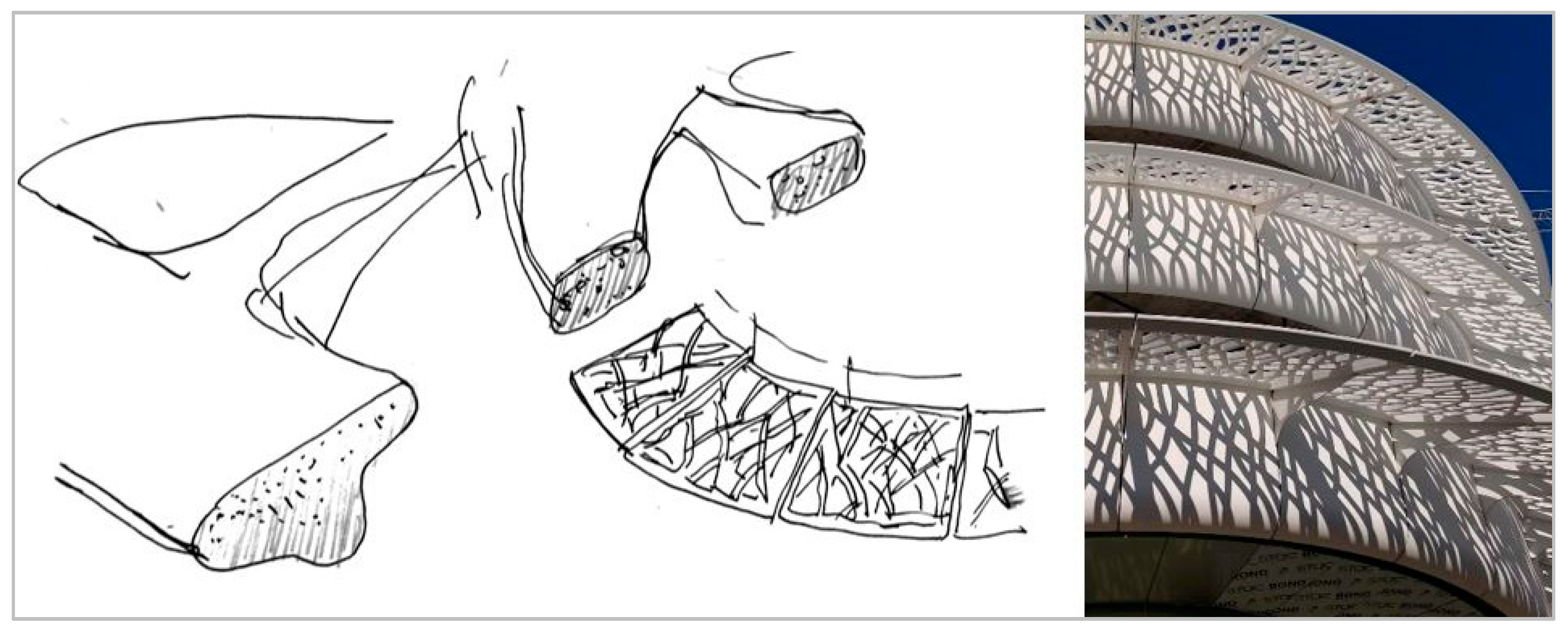
The predominant project elements are the huge solar protection eaves. Therefore, if an almost 3-m length projection is generated, the aim is to search for a big dimension protection component with extremely lightweight. The brainwave idea that leads to the construction of these ‘voilettes’ is the chosen material. UHPFRC is a material that can be designed and produced with high resistances, lightweight, and slender complex forms as a result of the fibbers added to the concrete (
Figure 10). The ‘voilettes’, including the high capacity of the UHPFRC, had a complex characteristic added-on. The components were perforated in more than 50
with only 5-cm thickness, leading to a mesh with 90 holes. Therefore, several tests should be conducted in the workshop. The resistance was guaranteed and did not break or deform significantly, similar to the development of the casts and the cast-fulfilled system. Finally, the ‘voilettes’ were built using two different modes: concave and convex.
2.5. Mohammed VI Tower, Rabat. Rafael de la Hoz. In progress.
The Mohammed VI Tower located in Rabat is currently under construction. It is designed with a height of 250 m and therefore will turn into the tallest building in the African continent. The façade diverges the north and south orientations, and the north skin searches for transparency with straight-up ribs termed ‘
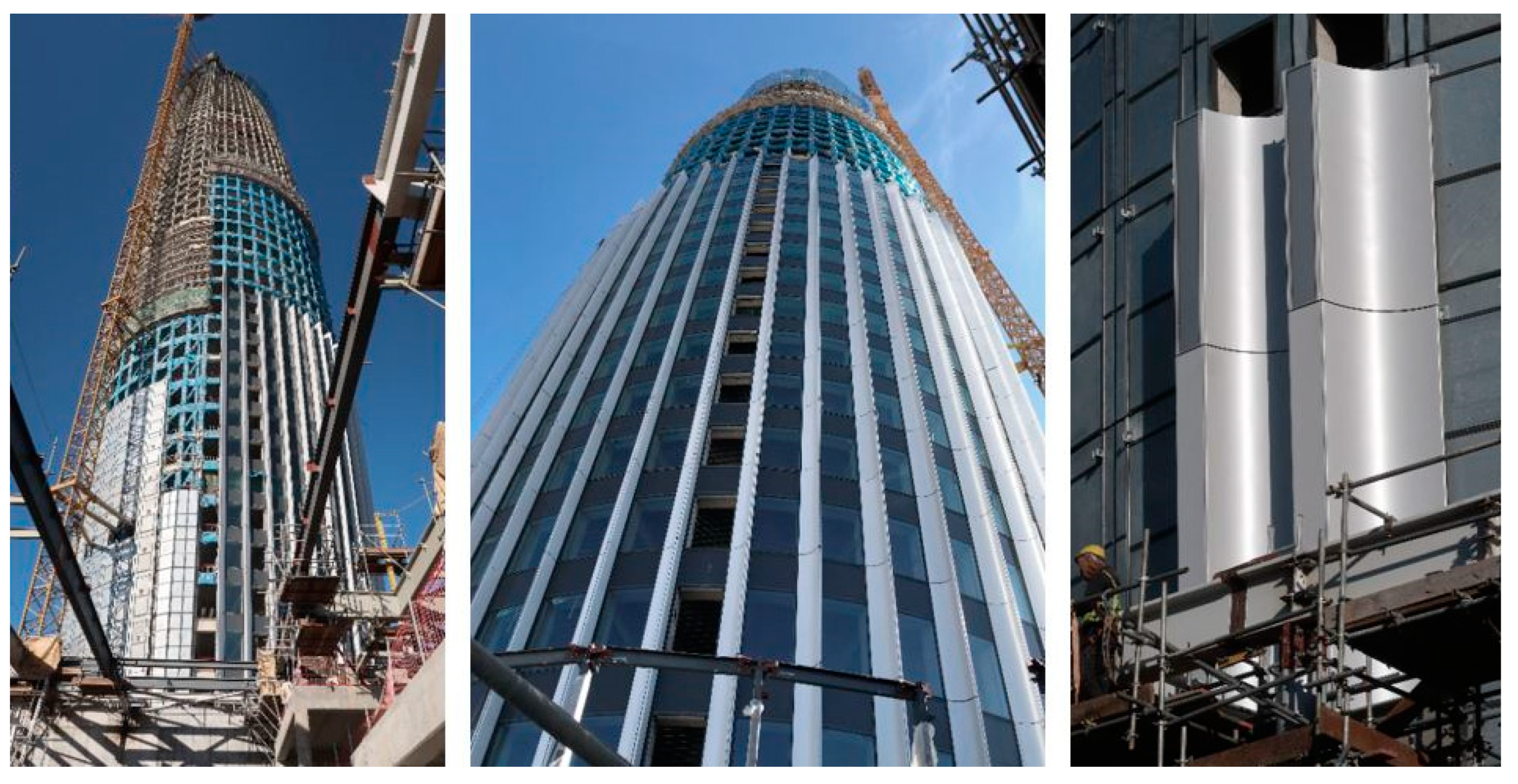
epines’ to accentuate the vertically. The south façade is perfectly opaque to introduce photovoltaic panels. Although they are conceptually different facades, they are resolved using the same construction system. All the façade enclosure is constructively solved with a modular curtain wall with different widths in the tower perimeter, following the project requirements and dimensions. The curtain of the north façade is modulated in 1,70 and 0,60 m modules, an alternating vision module, and an opaque module (
Figure 11). The 0,60-m opaque module is used to situate the white aluminium ‘
epines’ to remark the tower verticality and reflect light to the interior of the floors of the tower. The ‘
epines’ are suspended in the opaque curtain wall module with a tubular substructure that, in addition, stiffens it. The materiality of the ‘
epines’ was investigated in the prototype phase to verify if both the material and suspending system accomplish the constructive and aesthetic requirements. Conversely, in the south and intermediated façades the same system, i.e., an opaque modular curtain wall, is used. Overlaid with the suspended final cladding, which comprises three material types: aluminium sheets, photovoltaic panels, and tubular profiles for ventilation.
The brainwave in the Mohamed VI tower is the EPDM polymer rubber between the curtain wall modules that ensure water tightness in the façade, in addition to the possible movement that occurs in the modules because of structural deformation and adjustment of the double curvature (
Figure 12). The brainwave of the biggest project is one of the smallest and simplest elements in the construction system but accomplishes the resolution of the total façade cladding towing to its geometry.
3. Discussion
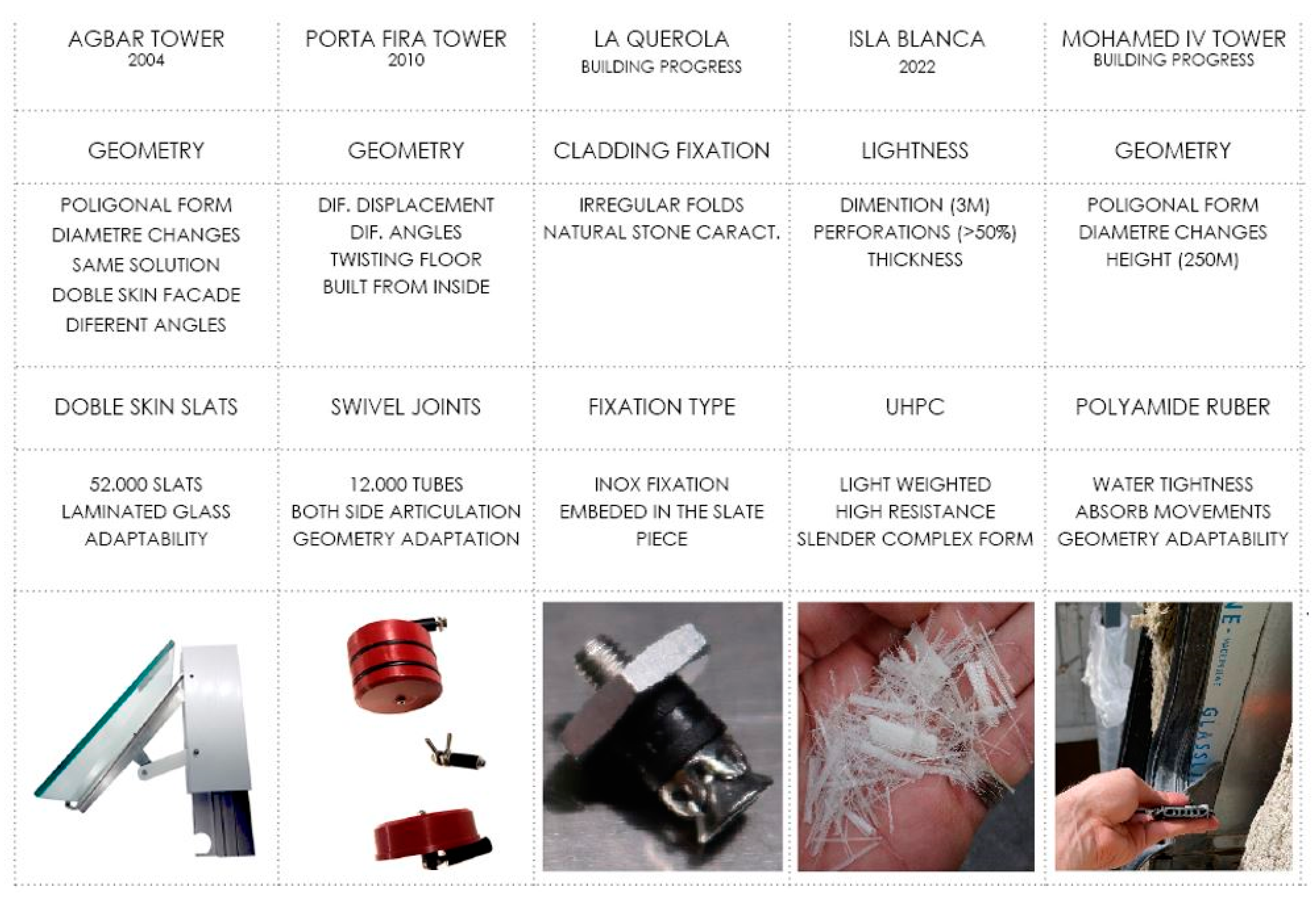
If the construction system of each case study is examined single-handed, it could be related to any type of construction without having to be an iconic building (
Figure 13). Therefore, a complex construction or extremely innovative solution should not necessarily be developed to resolve the façade detail of unique and sophisticated shape buildings. However, conventional construction systems applied in each case are assisted by the brainwave idea. Consequently, innovation occurs in a small element or standard system that is used differently from the one it was conceived, enabling one to face and resolve the complexity of the detail most simply. Notably, this fact is considered a working principle.
Therefore, these buildings can be considered test tube buildings in which the originality of the proposal is based on a simple combination of additional elements that are reformulated to be adapted to each specific case, creating innovations that will be applied in the rest of the buildings. Most of these innovations occur in the prototype development (
Figure 14), and therefore, a visual and constructive real-scale prototype should be built with definitive materials while developing the façade details. This enables, as in a laboratory, to perform successive corrections until all the proposals are validated, before production, testing the viability of the solution via formal and technical behaviours.
4. Conclusions
Construction techniques involve complex construction systems including several components, usually with standard systems permutations, thus forgetting system simplicity. Excessive complexity and, in some cases, overreaction are applied in detail without providing performance improvement but rather a cost increase and thus the possibility of having challenges when following the design details. The opportunity for façade consultants is to learn how to use complexity instead of avoiding it, designing façade details via simple or complicated processes. The detail or construction solution has to be improved by realizing technical tests and visual mock-ups, which is the key element to developing and enhancing solutions. Coherence between ideas, architectonic concepts, construction systems, products, and material and construction details must be guaranteed as an improvement method. Notably, a building can have the same external image but still be built using different construction techniques. However, in the construction field and equality conditions, simplicity is the way to quality. The brainwave idea is committed when the connection within different components is established. Therefore, it can be found in any position in which the standard systems are connected between them.
The brainwave idea is not accidental or fortuitous. It is the basis of creativity in many disciplines, and the cases detailed in this study are examples of the application of the brainwave idea in construction technology, which undoubtedly would not have been the first option chosen when trying to rationalize systems. Obtaining the brainwave idea in a technique and form is related to internal and continuous works in the study of a problem after a deductive process and is, therefore, of the relationships that may occur between all the elements involved in it. Consequently, craft, knowledge, talent, and dedication are the basis and will enable a good possibility of solving problems.
In the construction field and equality conditions simplicity is the way to quality.
The detail or construction solution has to be improved by realising a technical test and visual mockup.
The brainwave idea is not easily deducible from the problem and therefore depends on creativity.
The brainwave is directly related to a deductive process, which is based on craft, knowledge, talent, and dedication.
Author Contributions
Conceptualization, P-M.G. and X.F.P.; methodology, X.F.P.; validation, X.F.P., and P.M.G.; formal analysis, P.M.G.; investigation, X.F.P.; resources, X.F.P.; data curation, X.F.P.; writing—original draft preparation, X.F.P.; writing—review and editing, P.M.G.; visualization, P.M.G.; supervision, X.F.P. All authors have read and agreed to the published version of the manuscript.
Funding
This research received no external funding.
Conflicts of Interest
The authors declare no conflict of interest.
References
- Cajide, B.V.; Javier, F.; Cobo, C. El edificio icónico como comunicador de la arquitectura contemporánea. Estudio de las repercusiones sociales del edificio icónico a través de a casa da música de Porto. In Proceedings of the Actas icono14; 2011.
- Proust, E. How to achieve success in iconic construction projects: the iron triangle hegemony challenged. Environ. Eng. 2011. [Google Scholar]
- Ferrés Padró, X. Facade consultat, a process from the idea to the detail. In Proceedings of the Architecture & Construction - From concept to product; Birkhäuser, 2013.
- K. Yildiz, E. The importance of iconic buildings for the city image: Konya science center example. Iconarp Int. J. Arch. 2018, 6, 461–481. [CrossRef]
|
Disclaimer/Publisher’s Note: The statements, opinions and data contained in all publications are solely those of the individual author(s) and contributor(s) and not of MDPI and/or the editor(s). MDPI and/or the editor(s) disclaim responsibility for any injury to people or property resulting from any ideas, methods, instructions or products referred to in the content. |
© 2024 by the authors. Licensee MDPI, Basel, Switzerland. This article is an open access article distributed under the terms and conditions of the Creative Commons Attribution (CC BY) license (http://creativecommons.org/licenses/by/4.0/).
