1. Introduction
Gyroscopes [
1,
2] are sensors with varying levels of accuracy that can measure the angular velocity of a carrier around one or more axes in relation to an inertial reference frame [
3]. From the introduction of the concept of FOG based on the Sagnac effect [
4] to its large-scale integrated application [
5]. Its performance can meet the requirements of tactical-level applications and can be developed for navigation-level applications. FOG is a highly desirable component of strap-down inertial navigation systems (SINS) [
6,
7]. As it is an inertial sensor with exceptional environmental adaptability [
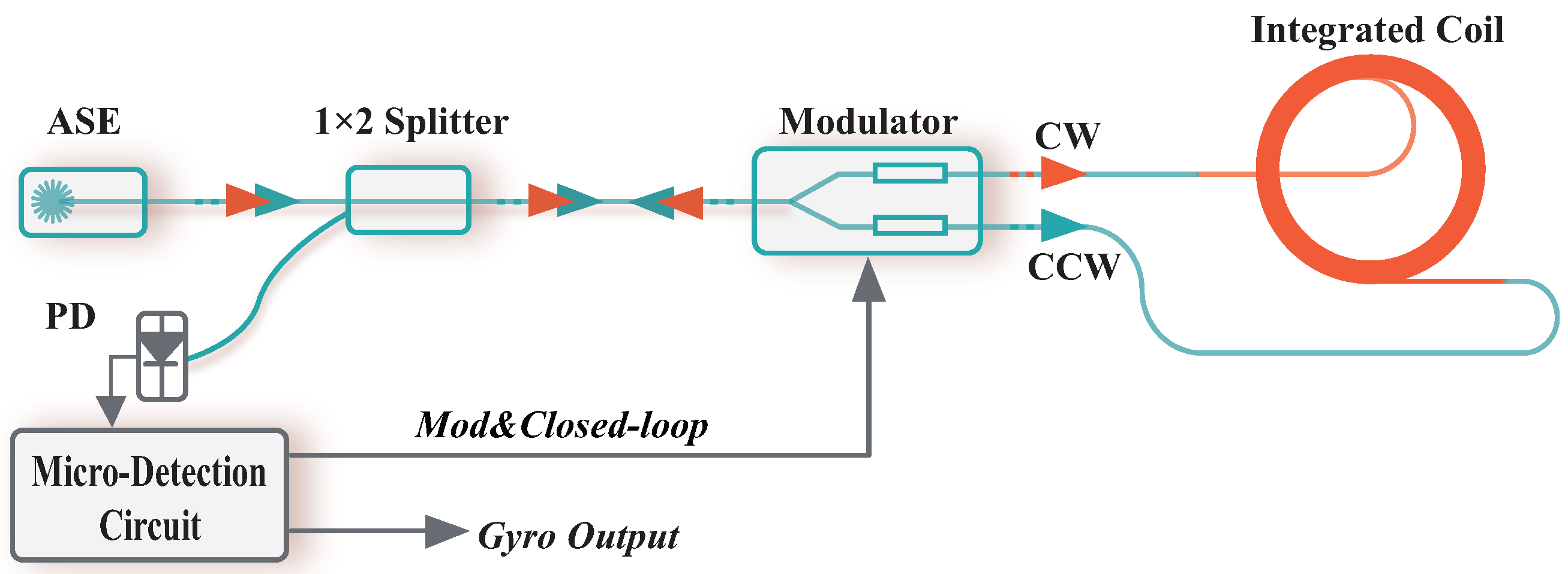
8]. The simplified construction is shown in
Figure 1.
SINS are autonomous dead reckoning (DR) [
10,
11] systems that utilize inertial measurement units (IMU) to calculate body navigation parameters. The prominence of FOG has been further elevated by the advent of SINS, which has enabled FOG to play a critical role in high-precision navigation and guidance applications. SINS initialization [
12,
13] is the process of determining initial values for the body’s position, velocity, and attitude in navigation coordinates. The initialization of attitude, also known as alignment, is the process of determining the initial values of the coordinate transformation matrix from the body frame (b-frame) to the navigation frame (n-frame). The precision of the initial alignment depends on the accuracy of the system’s calculations, and the speed of the initial alignment determines the system’s ability to respond rapidly. Some common methods are achieved by indirect coarse alignment and Kalman Filter: (
a) Carrier-phase-based initial yaw alignment, which is based on the principle of trajectory similarity [
14]. (
b) State transformation for the Kalman Filter mechanization with a newly converted velocity error model for SINS [
15,
16]. The methods mentioned above primarily use non-collinear vectors to explicitly construct expressions and solve corresponding values by inputting sensor data. However, it is a challenge to build an accurate model for a complex high-precision optical navigation system. If the algorithm design is not reasonable, it will result in a decrease in the accuracy of the entire system.
As a result of the advancement in deep learning [
17,
18,
19,
20], an increasing number of people have been trying to utilize neural networks to establish implicit mapping relationships and accomplish SINS alignment. In the early stages, researchers attempted to address the initial alignment problem by implementing basic machine learning algorithms, such as the BP neural network [
21,
22]. Nowadays, deep learning is widely utilized in navigation. CNNs are a subcategory of deep learning algorithms. They are designed to process grid-like data, such as images, and automatically learn and extract relevant features from the input data. For example, in the case of global positioning system outages, the navigation system can maintain a high level of accuracy by utilizing CNN [
23,
24]. In this paper, we introduce CNN as the network architecture to achieve data regression prediction and to perform the initial alignment of SINS. In the meantime, the intelligent optimization algorithm PSO [
25] is used to facilitate the rapid convergence of the network.
2. Materials and Methods
In this section, we offer a brief overview of the implementation principles of traditional alignment methods and introduce the initial alignment technique based on deep learning. Additionally, a method for further optimizing deep learning by incorporating the PSO algorithm is also presented. Finally, we present the experimental procedure.
2.1. Self-Alignment on a Fixed Platform
Self-alignment [
26,
27,
28] on a fixed platform is a static alignment process that is carried out while the vehicle is stationary relative to the Earth. It can be divided into coarse and fine alignment. Coarse alignment establishes an approximate direction cosine matrix, which forms the foundation for fine alignment. During fine alignment, the approximate direction cosine matrix obtained from coarse alignment is refined in real time using a Kalman filter.
2.1.1. Coarse Alignment
Coarse alignment involves two processes: leveling and gyroscope compassing. The output of the accelerometer is referred to as specific force, which represents the variance between the vehicle’s acceleration and the local gravity field. When the vehicle is at rest, the acceleration is zero. Therefore, the output of the accelerometer represents the component of the local gravity on the three axes.
Roll and pitch can be calculated using the following equation:
where
and
represent the projections of the output of the three-axis accelerometer onto the vehicle coordinate system and the navigation coordinate system, respectively.
is the rotation matrix that projects the vector from the b-frame to the n-frame, while
g denotes the gravity vector in the local area. Additionally,
and
correspond to the pitch angle and roll angle, respectively.
After determining the horizontal direction by sensing the gravitational acceleration, we continue to determine the yaw by sensing the Earth’s rotation rate. When SINS is stationary, the principle underlying gyroscope compassing is that the gyroscope measurements are determined by the Earth’s rotation vector and the vehicle’s attitudes.
Yaw can be calculated using the following equation:
where
represents the output of the gyroscope’s three axes,
denotes the rotation matrix that projects the vector from the b-frame to the n-frame,
and
are the angular velocity of the Earth’s rotation and the associated angular velocity, and
,
, and
respectively represent yaw, pitch, and roll. Additionally,
stands for the local latitude.
We can calculate the roll, pitch, and yaw angles using equations (1) and (2), and then derive the corresponding direction cosine matrix. Coarse alignment enables a small angle error approximation, which facilitates further fine alignment.
2.1.2. Fine Alignment
After coarse alignment, any remaining errors in the attitude matrix need to be corrected. A Kalman filter is used to estimate the misalignment angles, velocity errors, and position errors. These estimates are then utilized to correct the inertial navigation system and reduce the disparity between the calculated navigation coordinates and the actual navigation coordinates.
The Kalman filter is only suitable for linear systems with precise models and known statistical characteristics of noise. However, in practical applications, it is often challenging to obtain accurate mathematical models and statistical characteristics of the noise in the system during dynamic motion. This can lead to decreased filtering accuracy or even filter divergence. Therefore, the estimation of the state of nonlinear systems, including Extended Kalman filter (EKF) [
29] has received widespread attention in the field of inertial navigation. Typically, the recursive equations of EKF include prediction and update steps.
Update step:
where
is the prior estimate of the state,
is the posterior estimate of the state,
is the prior estimate of the state covariance matrix,
is the posterior estimate of the state covariance matrix,
is the control input,
is the measurement,
is the state transition matrix,
is the process noise covariance matrix,
is the observation matrix,
is the measurement noise covariance matrix, and
is the Kalman gain.
Although performing the above two steps can calculate the initial attitude of SINS, self-alignment on a fixed platform is an ideal scenario. In real-world applications, it is difficult to achieve absolute static conditions. SINS is sensitive to abnormal vibrations, and even slight vibrations that are imperceptible to humans can have a significant impact on the accuracy of alignment when introduced into the navigation system. To mitigate the interference caused by these noises, it is typically necessary to develop an error model. However, due to the complexity and nonlinearity of SINS, this task becomes challenging, and accurately modeling a specific system is difficult.
2.2. Deep Learning-Based Initial Alignment
We propose a deep learning-based technique for initial alignment, with the aim of improving the accuracy and speed of the process. This approach leverages the robust adaptability, fault recovery capability, and advantages in handling nonlinear problems offered by deep learning. While CNN is primarily utilized for image processing, its parallel computing advantages can be fully harnessed by linearizing the convolution layer, thereby accelerating the training process.
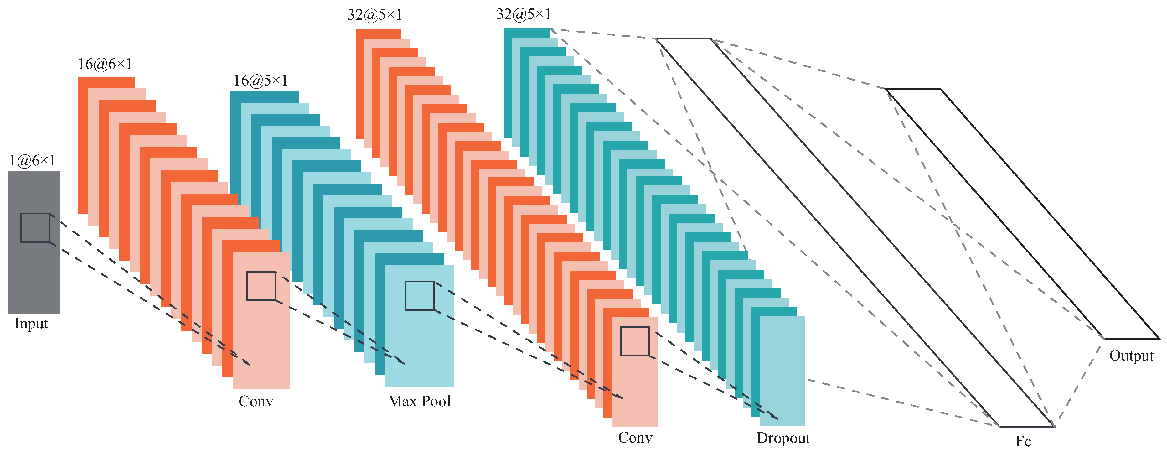
Figure 2 depicts this model in detail.
In this diagram, the batch normalization layer is hidden, and its role is to stabilize the data segment and alleviate the problem of vanishing gradients. The output layer of the network contains a quaternion that describes the attitude. The expression for the quaternion is as follows:
where
,
,
and
denote the real and imaginary parts of the quaternion.
The error correction of the estimate of the quaternion
q can be represented by multiplying the true value of
q by the inverse of the estimated value of
q. This correction factor can be used to adjust the estimated value of the quaternion, bringing it closer to the true value:
The error in attitude towards the truth value is presented as follows:
where
represents the sequence of estimates,
denotes the horizontal error,
T stands for discrete time, and
n indicates the sample size. The estimated quaternion output should have minimal attitude error.
The loss function of the model is represented by the following formula:
where the issue of gradient explosion caused by the arccos function can be circumvented by using linear terms instead. This approach makes the gradient smoother and prevents it from exploding.
PSO is a population-based stochastic optimization technique proposed by Eberhart and Kennedy [
30]. Each individual in the swarm adjusts its search pattern based on its own experience and the collective experience of the group.
The particle update process is primarily based on the following two formulas:
where
,
,
and
are the positions, the velocities, the current optimal location and the global optimal location of the i particle in the k generation and d dimensions, respectively;
and
are random number between 0.1 and 0.9; And
and
are the parameters that adjust the balance of
and
.
The network framework proposed in this paper is implemented using MATLAB. We use an RTX-3060 GPU to train the network. Moreover, we utilize the stochastic gradient descent with momentum optimizer for 6400 iterations and incorporate PSO algorithm to dynamically adjust the learning rate [
31,
32,
33].
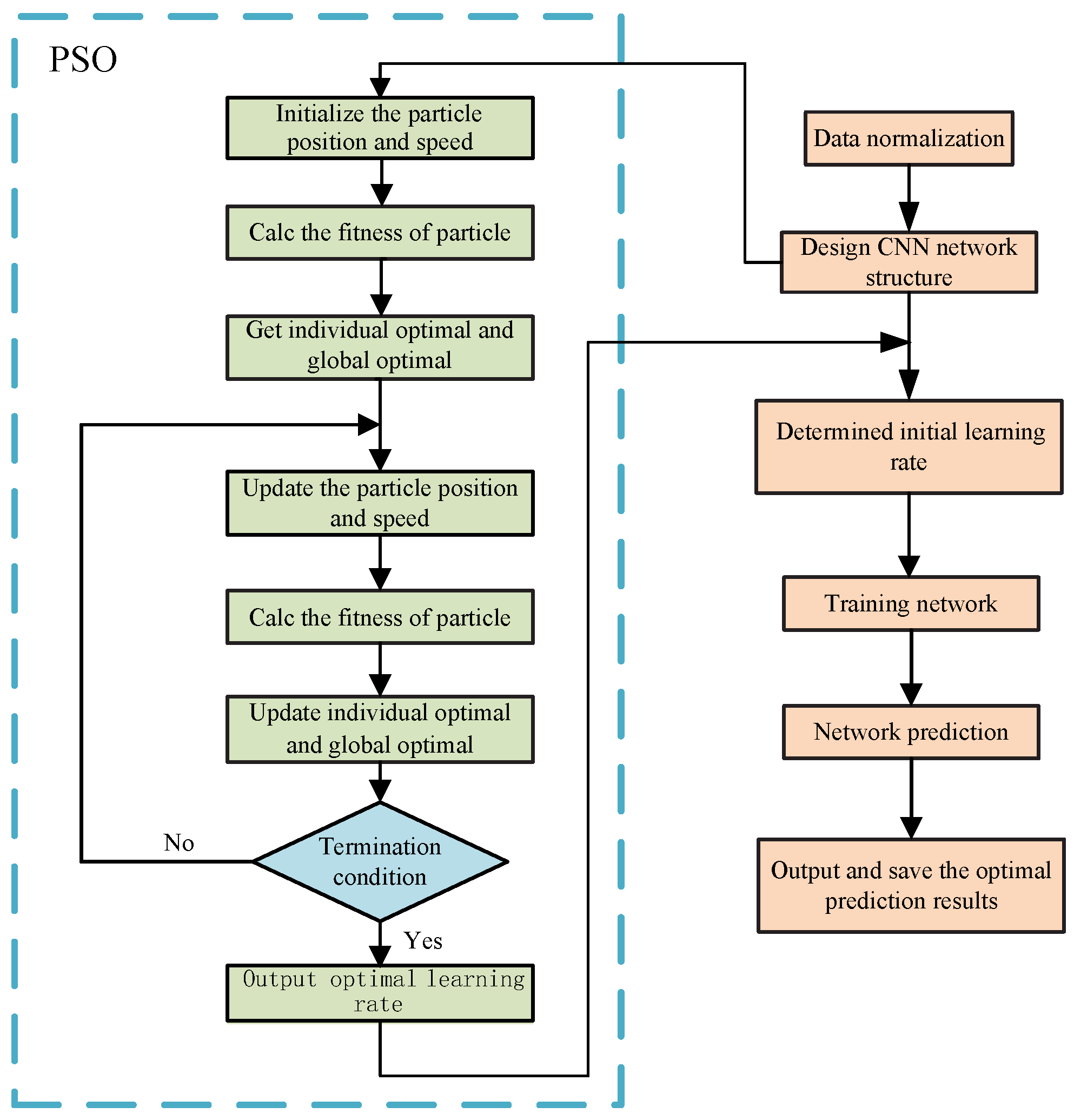
Figure 3 illustrates the flow diagram of PSO-CNN.
2.3. Experiment Description
The alignment methods mentioned above have been evaluated and verified through experiments conducted in laboratory static environments and simulated open-sky areas. The IMU static data was collected on a laboratory static base platform to minimize external interference on the system. The IMU was placed on a stationary base platform for four hours with a sampling frequency of
. In these tests, we used a mid-precision FOG called LKF-FS050 (Wuhan Liocrebif Technologies Co., Ltd) to collect the data.
Table 1 lists the main parameters of the FOG.
As we utilize supervised learning [
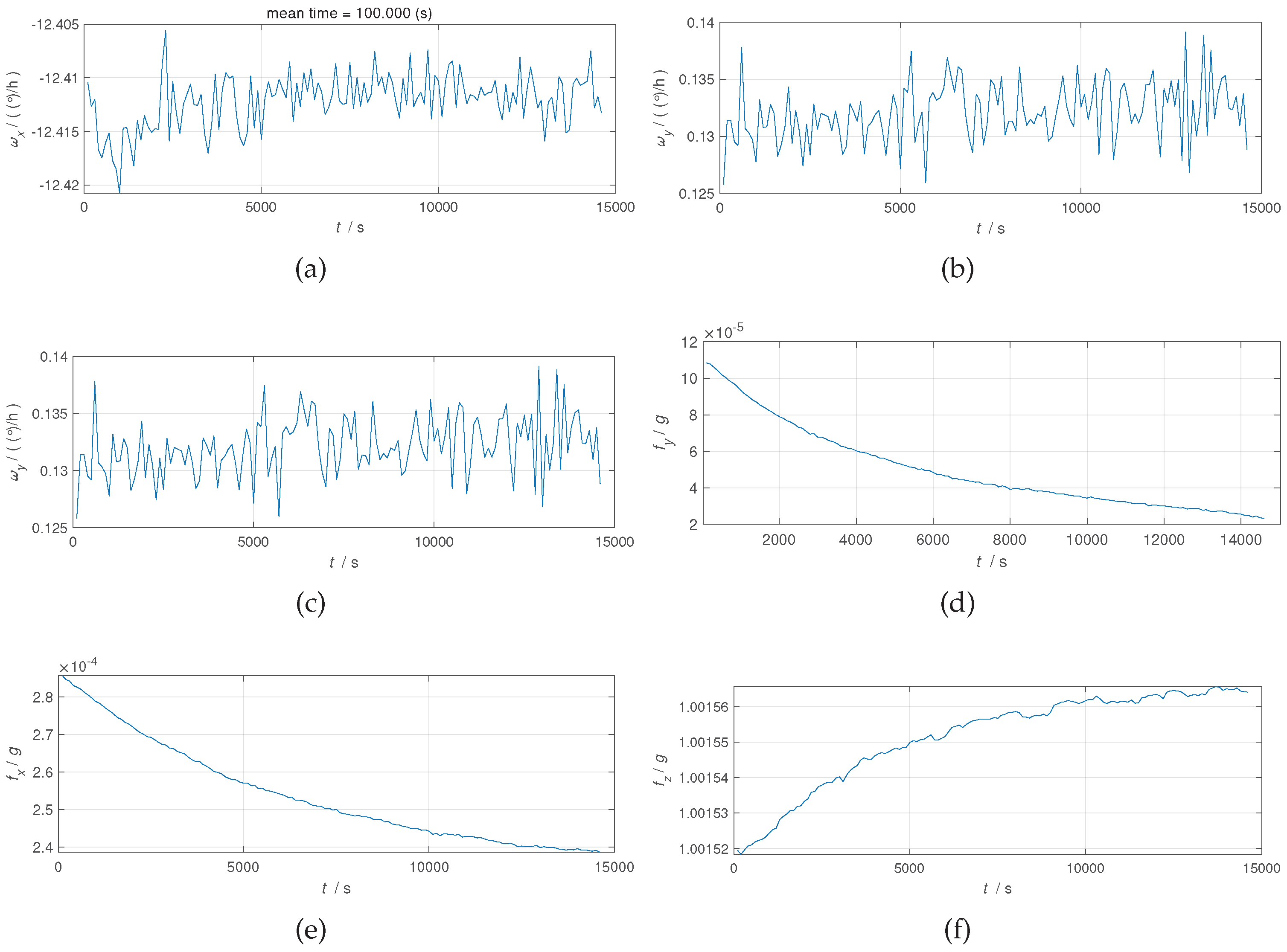
34], we need to label the dataset with the corresponding unit quaternions, which serve as the ground truth. The raw IMU outputs consist of seven parameters, including the gyroscope outputs for the three axes, accelerometer outputs for the three axes, and the timestamp of each measurement.
Figure 4 shows the raw data from the sensor.
The Euler angle describes the orientation of an object using three angles in an intuitive manner. On the other hand, a quaternion is a representation that facilitates computer understanding and computation. In navigation, it is often necessary to convert between these two formats. Converting real-valued Euler angles to quaternions can make attitude calculations more convenient. Here is the formula for Euler’s angular rotation quaternion.
where
,
and
represent the rotation angles around the
x,
y and
z axes, respectively. While
,
,
and
denote the real and imaginary parts of the quaternion. It should be noted that Euler angles are rotated in
order, i.e., first rotated around the
z axis by
degrees, then rotated around the rotated
y axis by
degrees, and finally rotated around the rotated
x axis by
degrees.
To further validate the effectiveness of the algorithm, we simulated error-free flight data and substituted the initial alignment stage with a trained model.
3. Results and Discussion
This section should offer a brief and accurate description of the experimental results, their interpretation, and the conclusions that can be drawn from the experiment.
Figure 4 illustrates that in a navigation system, the gyroscope values are typically more erratic, indicating a greater influence of noise. Therefore, more advanced processing of the gyroscope is necessary at every stage of calibration and alignment to guarantee the overall accuracy of the INS. Based on the origin data, we compare the results of two initial alignment methods: (
a) SAFP: self-alignment on a fixed platform; (
b) PSO-CNN: a network-based alignment method.
As can be seen from the above
Table 2, the initial alignment pitch, roll and yaw errors are reduced by an average of
,
and
respectively. For manual modeling calculations, many preconditions are often set in advance, such as assuming that the error contains only white noise. The actual situation is more complicated than assumed, and when reality fails to meet these assumptions, the entire system will perform poorly. One advantage of deep learning is that it does not require the construction of a model in advance; instead, it learns to automatically adapt to the corresponding input-output mapping relationship. The following
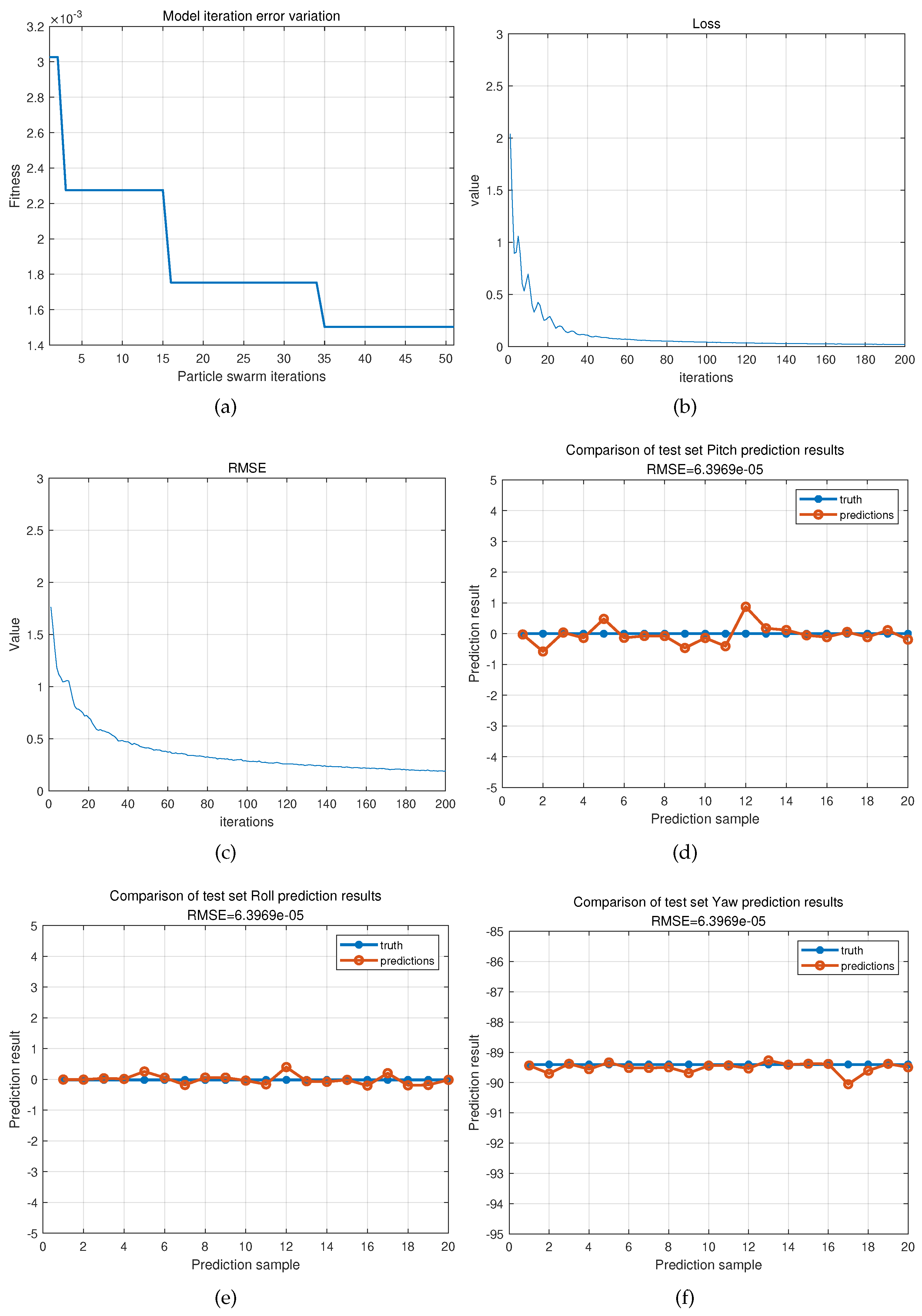
Figure 5 depicts some of the training processes discussed in this article.
Finally, a dataset of UAV inertial navigation flight data was simulated at a flight speed of
, covering a distance of approximately
over a collection time of
with a sampling frequency of
. The initial stationary period lasted for the first
. Subsequently, by using an INS/GNSS combination for smoothing, accurate IMU and AVP reference values were obtained through inversion. We utilized the initial alignment method outlined in this article to aid in the initialization of INS. The calculation results and errors are depicted in the
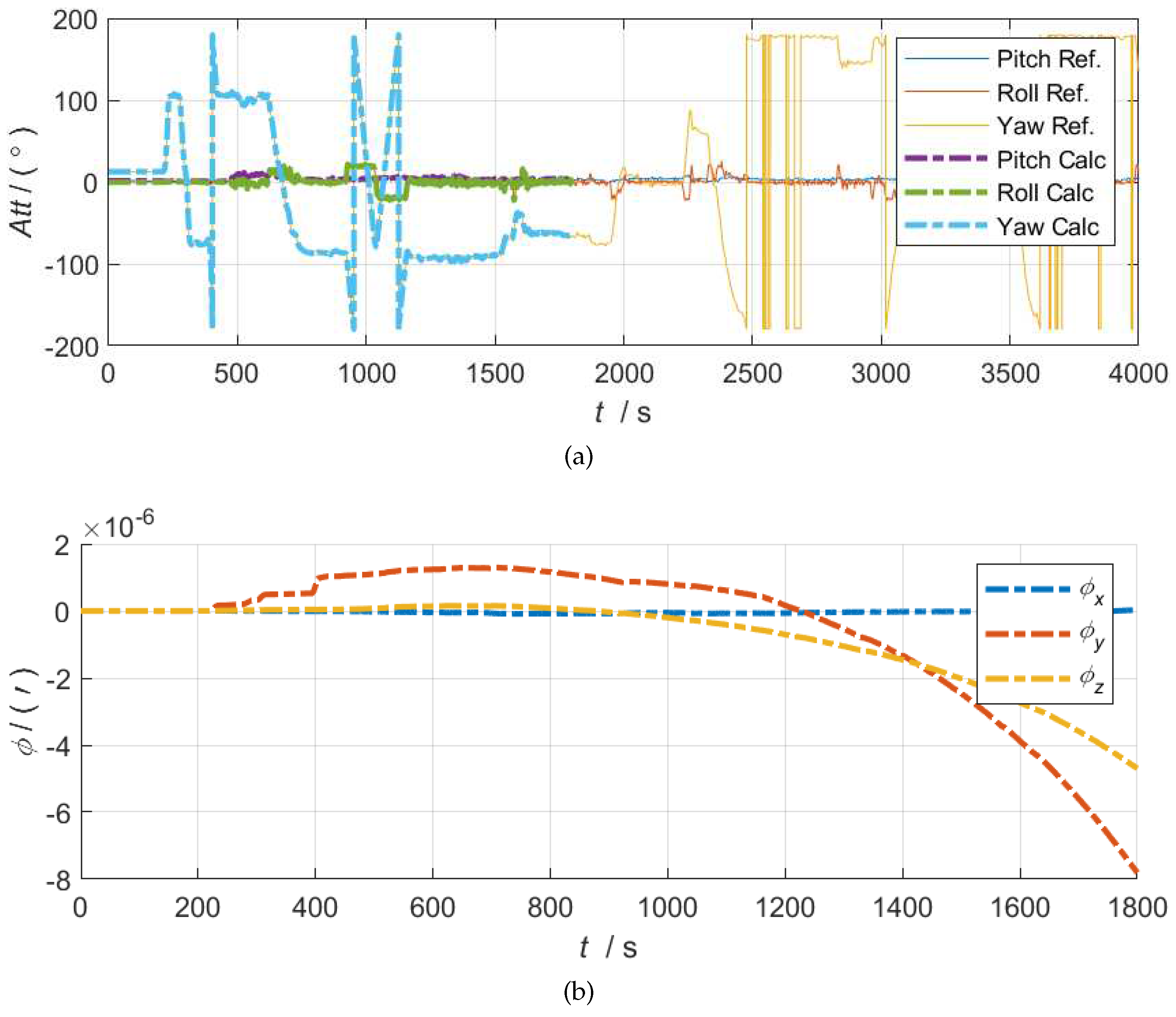
Figure 6. By observing the figure 6(a), it can be found that the solution based on neural network alignment closely matches the reference truth curve. This confirms the feasibility of the proposed method. In addition, the figure 6(b) illustrates the divergence of INS errors over time, which is a normal phenomenon. In practical applications, the cumulative error is typically calibrated in conjunction with satellite navigation.
Figure 6.
On the top side, the comparison shows the results of the actual solution for 30 minutes alongside the reference truth value. The bottom side shows the corresponding attitude error curve.
Figure 6.
On the top side, the comparison shows the results of the actual solution for 30 minutes alongside the reference truth value. The bottom side shows the corresponding attitude error curve.
Future research could expand to include model selection and optimization. As we all know, the development of neural networks has already resulted in various types. In this paper, we endeavored to apply CNN to the alignment of INS, however, there are still limitations. For example, we did not compare it with other networks such as RNN [
35] and BP [
36]. A more complex model does not necessarily guarantee better performance. Frequently, it is essential to modify the model according to practical applications in order to maximize its value. Therefore, our primary focus will be on selecting the appropriate neural network model and conducting targeted fine-tuning.
4. Conclusions
FOG occupies an important position in the middle and high-end market of inertial navigation. The incorporation of an outstanding initial alignment method improves the establishment and calibration of the navigation system, thereby optimizing the performance of the FOG. This paper investigates an initial alignment method for FOG using CNN based on PSO. The proposed method utilizes a neural network to facilitate the alignment process and leverages optimization techniques to expedite the convergence of the network. The results show that the proposed method is more accurate than certain traditional alignment methods. Furthermore, the approach successfully achieved orbit matching in the simulated flight data, where the attitude, velocity, and position are obtained using an Integrated Navigation System combination for smoothing. The experimental results demonstrate that this method can also contribute to the field of integrated navigation and has practical value.
Overall, we have confirmed the feasibility and practicality of using deep learning for the initial alignment of the navigation system through the above experiments. This research provides insight into future work on INS initial alignment.
Author Contributions
Methodology, Hunzhuo Zhang; Software, Hunzhuo Zhang; Validation, Hunzhuo Zhang; Writing – original draft, Hunzhuo Zhang; Writing – review & editing, Duan Huang. All authors have read and agreed to the published version of the manuscript.
Funding
This work is supported by the National Nature Science Foundation of China (Grants No. 61801522) and the National Nature Science Foundation of Hunan Province, China (Grant No. 2019JJ40352).
Data Availability Statement
Conflicts of Interest
The authors declare no conflict of interest.
References
- Bergh, R.; Lefevre, H.; Shaw, H. An overview of fiber-optic gyroscopes. Journal of Lightwave Technology 1984, 2, 91–107. [Google Scholar] [CrossRef]
- Passaro, V.M.; Cuccovillo, A.; Vaiani, L.; De Carlo, M.; Campanella, C.E. Gyroscope technology and applications: A review in the industrial perspective. Sensors 2017, 17, 2284. [Google Scholar] [CrossRef] [PubMed]
- Dell’Olio, F.; Natale, T.; Wang, Y.C. ; others. Miniaturization of Interferometric Optical Gyroscopes: A Review. IEEE Sensors Journal 2023. [Google Scholar] [CrossRef]
- Lawrence, A. Modern inertial technology-Navigation, guidance, and control. NASA STI/Recon Technical Report A 1993, 93, 39795. [Google Scholar]
- Guo, Z.; Jin, J.; Wang, X.; Song, N.; Song, J.; Xu, X.; Zhang, Z. Three-axis Interferometric Fiber Optic Gyroscope with Silica Integrated Coupler Chip. IEEE Sensors Journal 2023. [Google Scholar] [CrossRef]
- Engelsman, D.; Klein, I. Information-Aided Inertial Navigation: A Review. IEEE Transactions on Instrumentation and Measurement 2023, 72, 1–18. [Google Scholar] [CrossRef]
- Jekeli, C. Inertial navigation systems with geodetic applications. Walter de Gruyter GmbH & Co KG, 2023. [Google Scholar]
- Liu, D.; Li, H.; Wang, X.; Liu, H.; Ni, P.; Liu, N.; Feng, L. Interferometric optical gyroscope based on an integrated silica waveguide coil with low loss. Optics Express 2020, 28, 15718–15730. [Google Scholar] [CrossRef]
- Tran, M.A.; Komljenovic, T.; Hulme, J.C.; Kennedy, M.; Blumenthal, D.J.; Bowers, J.E. Integrated optical driver for interferometric optical gyroscopes. Optics express 2017, 25, 3826–3840. [Google Scholar] [CrossRef]
- Ojeda, L.; Borenstein, J. Personal dead-reckoning system for GPS-denied environments. 2007 IEEE International Workshop on Safety, Security and Rescue Robotics. IEEE, 2007, pp. 1–6.
- Wu, Y.; Zhu, H.B.; Du, Q.X.; Tang, S.M. A survey of the research status of pedestrian dead reckoning systems based on inertial sensors. International Journal of Automation and Computing 2019, 16, 65–83. [Google Scholar] [CrossRef]
- Chang, L.; Qin, F.; Xu, J. Strapdown inertial navigation system initial alignment based on group of double direct spatial isometries. IEEE Sensors Journal 2021, 22, 803–818. [Google Scholar] [CrossRef]
- Li, L.; Yulong, H.; Lubin, C.; Yonggang, Z. Development and prospects of initial alignment method for strap-down inertial navigation system. Chinese Journal of Ship Research 2022, 17, 301–313. [Google Scholar]
- Zhang, T.; Liu, S.; Chen, Q.; Feng, X.; Niu, X. Carrier-Phase-Based Initial Heading Alignment for Land Vehicular MEMS GNSS/INS Navigation System. IEEE Transactions on Instrumentation and Measurement 2022, 71, 1–13. [Google Scholar] [CrossRef]
- Wang, M.; Wu, W.; Zhou, P.; He, X. State transformation extended Kalman filter for GPS/SINS tightly coupled integration. Gps Solutions 2018, 22, 1–12. [Google Scholar] [CrossRef]
- Wang, M.; Wu, W.; He, X.; Li, Y.; Pan, X. Consistent ST-EKF for long distance land vehicle navigation based on SINS/OD integration. IEEE Transactions on Vehicular Technology 2019, 68, 10525–10534. [Google Scholar] [CrossRef]
- LeCun, Y.; Bengio, Y.; Hinton, G. Deep learning. nature 2015, 521, 436–444. [Google Scholar] [CrossRef] [PubMed]
- Alzubaidi, L.; Zhang, J.; Humaidi, A.J.; Al-Dujaili, A.; Duan, Y.; Al-Shamma, O.; Santamaría, J.; Fadhel, M.A.; Al-Amidie, M.; Farhan, L. Review of deep learning: Concepts, CNN architectures, challenges, applications, future directions. Journal of big Data 2021, 8, 1–74. [Google Scholar] [CrossRef] [PubMed]
- Méndez, M.; Merayo, M.G.; Núñez, M. Machine learning algorithms to forecast air quality: a survey. Artificial Intelligence Review 2023, 1–36. [Google Scholar] [CrossRef] [PubMed]
- Li, Y.; Cao, J.; Xu, Y.; Zhu, L.; Dong, Z.Y. Deep learning based on Transformer architecture for power system short-term voltage stability assessment with class imbalance. Renewable and Sustainable Energy Reviews 2024, 189, 113913. [Google Scholar] [CrossRef]
- Tekinalp, O.; Ozemre, M. Artificial neural networks for transfer aligment and calibration of inertial navigation systems. AIAA Guidance, Navigation, and Control Conference and Exhibit, 2001, p. 4406.
- Xinlong, W.; Liangliang, S. Solution of transfer alignment problem of SINS on moving bases via neural networks. Engineering Computations 2011, 28, 372–388. [Google Scholar] [CrossRef]
- Zhi, Z.; Liu, D.; Liu, L. A performance compensation method for GPS/INS integrated navigation system based on CNN–LSTM during GPS outages. Measurement 2022, 188, 110516. [Google Scholar] [CrossRef]
- Zhao, S.; Zhou, Y.; Huang, T. A novel method for AI-assisted INS/GNSS navigation system based on CNN-GRU and CKF during GNSS Outage. Remote Sensing 2022, 14, 4494. [Google Scholar] [CrossRef]
- Wang, D.; Tan, D.; Liu, L. Particle swarm optimization algorithm: an overview. Soft computing 2018, 22, 387–408. [Google Scholar] [CrossRef]
- Haijian, X.; Tao, W.; Xinghu, C.; Jintao, W.; Fei, L. Anti-interference self-alignment algorithm by attitude optimization estimation for SINS on a rocking base. Journal of Systems Engineering and Electronics 2023, 34, 1333–1342. [Google Scholar] [CrossRef]
- Chen, Q.; Lin, H.; Kuang, J.; Luo, Y.; Niu, X. Rapid Initial Heading Alignment for MEMS Land Vehicular GNSS/INS Navigation System. IEEE Sensors Journal 2023, 23, 7656–7666. [Google Scholar] [CrossRef]
- Jin, K.; Chai, H.; Su, C.; Yin, X.; Xiang, M. A novel adaptive nonlinear Kalman filter scheme for DVL-aided SINS alignment in underwater vehicles. Signal Processing 2023, 209, 109045. [Google Scholar] [CrossRef]
- Pei, F.; Yang, S.; Yin, S. In-motion initial alignment using state-dependent extended Kalman filter for strapdown inertial navigation system. IEEE Transactions on Instrumentation and Measurement 2020, 70, 1–12. [Google Scholar] [CrossRef]
- Eberhart, R.; Kennedy, J. Particle swarm optimization. Proceedings of the IEEE international conference on neural networks. Citeseer, 1995, Vol. 4, pp. 1942–1948.
- Khalifa, M.H.; Ammar, M.; Ouarda, W.; Alimi, A.M. Particle swarm optimization for deep learning of convolution neural network. 2017 Sudan conference on computer science and information technology (SCCSIT). IEEE, 2017, pp. 1–5.
- Liang, J.; Yang, H.; Gao, J.; Yue, C.; Ge, S.; Qu, B. MOPSO-based CNN for keyword selection on Google ads. IEEE Access 2019, 7, 125387–125400. [Google Scholar] [CrossRef]
- Zhang, X.; Tian, Y.; Zheng, X. Optimal design of fragment-type antenna structure based on PSO-CNN. 2019 International Applied Computational Electromagnetics Society Symposium-China (ACES). IEEE, 2019, Vol. 1, pp. 1–2.
- Caruana, R.; Niculescu-Mizil, A. An empirical comparison of supervised learning algorithms. In Proceedings of the 23rd international conference on Machine learning; 2006; pp. 161–168. [Google Scholar]
- Sherstinsky, A. Fundamentals of recurrent neural network (RNN) and long short-term memory (LSTM) network. Physica D: Nonlinear Phenomena 2020, 404, 132306. [Google Scholar] [CrossRef]
- Ding, S.; Su, C.; Yu, J. An optimizing BP neural network algorithm based on genetic algorithm. Artificial intelligence review 2011, 36, 153–162. [Google Scholar] [CrossRef]
|
Disclaimer/Publisher’s Note: The statements, opinions and data contained in all publications are solely those of the individual author(s) and contributor(s) and not of MDPI and/or the editor(s). MDPI and/or the editor(s) disclaim responsibility for any injury to people or property resulting from any ideas, methods, instructions or products referred to in the content. |
© 2024 by the authors. Licensee MDPI, Basel, Switzerland. This article is an open access article distributed under the terms and conditions of the Creative Commons Attribution (CC BY) license (http://creativecommons.org/licenses/by/4.0/).
