Preprint
Article

Uncertainty Constraint on Headphone Secondary Path Function for Designing Cascade Biquad Feedback Controller with Improved Noise Reduction Performance

Altmetrics

Downloads

99

Views

16

Comments

0

A peer-reviewed article of this preprint also exists.

This version is not peer-reviewed

Submitted:

05 February 2024

Posted:

05 February 2024

You are already at the latest version

Alerts
Abstract
The uncertainty in the secondary path of an Active Noise Control (ANC) headphone affects the waterbed effect and stability of the feedback system. This study focuses on the uncertainty of the secondary path when real users wear headphones, and proposes a new uncertainty constraint based on the measured results of the secondary path transfer function under different wearing conditions of dummy head and limited subjects. This constraint and a cascaded second-order infinite impulse response filter with fixed coefficients are used to formulate a control strategic function, which is optimized by the Improved Grey Wolf Optimizer (IGWO) algorithm to obtain the optimal controller with better noise reduction performance. The proposed method and simulation model are validated based on the experimental test results. The results demonstrate that the safety factor and waterbed suppressing factor contained in the proposed uncertainty constraint ensures more stable noise reduction and effective suppression of the waterbed effect for new subjects without a priori data.
Keywords: 
Subject: Engineering  -   Electrical and Electronic Engineering

1. Introduction

In the field of commercial headphone, ANC has become a common application [1]. Controllers in this realm are classified into two categories based on the time-variability of their filtering coefficients: fixed controllers and adaptive controllers. Fixed controllers contribute to reduced computational demands and extended battery life, thereby improving the standby time of headphones. Recently, Bai et al. [2] found that com-pared to adaptive controller, a fixed controller had achieved satisfactory noise reduction performance and signal tracking quality, which are highly valuable merits in practical applications.
ANC controllers are mainly divided into feedforward, feedback, and hybrid con-trollers in terms of their control structures. Notably, the feedback control strategies have been paid particular attention in long-history research [3]. The introduction of feedback mechanisms leads to two primary issues: firstly, according to the Bode sensitivity integral theorem, reducing low-frequency noise often results in the amplification of noise at other frequencies, a phenomenon commonly known as the "waterbed effect" [4]; secondly, the stability of the system varies across different usage environments, primarily owing to the impact of secondary path uncertainty [5,6] on system stability. Therefore, the basic principle of designing a feedback controller for ANC headphone is to maximize the low-frequency noise reduction performance while robustly maintaining the stability of the system, and to limit the noise enhancement at high frequencies.
Rafaely [7] pointed out that owing to the additional delays in a digital system, the bandwidth often becomes limited. The controllers for ANC headphones were initially implemented using analog circuits, with various design methods proposed by re-searchers such as Bai and Lee [8], Pawełczyk [9], and Hu et al. [10,11]. However, ana-log circuits have such drawbacks as significant discrete component errors and temperature drift, deteriorating the noise reduction performance and even system stability, so precise and low-power controller designs are needed in practical applications.
The uncertainty of the secondary path exceeds the deviation of the controller, of-ten leading to stability issues. The modeling errors of the secondary path may deteriorate the stability bound of the system [12]. Eriksson and Allie [13] first attempted to use random noise for online identification of a system's secondary path, while Morgan [14] proposed a prediction method applicable for both online and offline identification. However, the method of online identification with added noise is not suitable for ANC headphones as the identification error signal may contaminate the error signal of the noise reduction system itself. Given the close relation of headphone systems to human hearing, the presence of identification noise is unacceptable. Gan discussed using mu-sic or speech signals present in the headphone system as identification signals for the secondary path [15]. More recently, Yang et al. [16] proposed a method to control the identification error energy, and the system stability was significantly improved, although further research is required for headphone applications.
In practice, the transfer function of a headphone's secondary path is usually obtained through offline identification, and then is constrained by disk [17]. The uncertainty in the secondary path manifests mainly in the variance between a single head-phone's use by a single subject or a dummy head, in terms of wearing and removing the headphones, and the differences in multiple wearings by one or multiple subjects. Zhao et al. [18] noted that headphone puton and takeoff introduces large variance in the transfer functions of the secondary path, affecting the convergence of the adaptive system, and this variance can be reduced using the IMC feedback control implemented with analog circuits. Yu and Hu [10] used the results of four wearings to establish the controller's objective function and constraints, and then created an analog circuit con-troller. Guldenschuh and Callafon [19] found that the low-frequency drastic changes in the secondary path when putting on and removing headphones could be identified by an adaptive filter, based on which a feasible weighting coefficient update rule was established through experiments. Leading companies like BOSE, SONY and Apple have adopted proximity sensors offering quick and accurate responses in their ANC headphones to monitor the states of wearing and removal [29,30,31], and this approach can replace algorithmic detection from an engineering application perspective, reducing the algorithm's consumption of system power. For the latter case, Ti’s engineer Krishnamurthy et al. [20] used the average result of 10 real subjects to obtain the secondary path transfer function, and employed a smaller update coefficient to handle the greater variance. Benois and Zolzer [21] constructed different weighting coefficient constraints using real secondary path data from two dummy heads and six subjects wearing the headphones at three different angles, and used the SQP algorithm to de-rive the FIR filter and compared the results. Hilgemann and Jay [22] built an uncertainty model using the real part of 78 secondary path transfer functions tested on a single subject, and also used the SQP algorithm to calculate the FIR filter.
However, the implementation methods mentioned above either use analog circuits or FIR filters. Analog circuits have significant errors, and the FIR controllers will introduce additional delay and cannot meet the requirements of current ANC head-phones. Wang et al. [23] and An et al. [24] implemented controller designs using the IIR filters, and optimized them with the genetic optimization algorithm (GA) combined with the Nelder-Mead (NM) algorithm and differential evolution (DE) algorithm, respectively. In the former controller, the application of twice optimization increased the system complexity, while the latter controller based on the DE algorithm operates directly in continuous space, facilitating the global minimum search but bringing high computational demand [25]. The GWO [26] algorithm and its improved version, IGWO, as typical representatives of swarm intelligence algorithms, are characterized by their simple structure, minor parameter adjustment, and ease of implementation. They contain an information feedback mechanism, and a balance is achieved between local optimization and global search, thus offering good performance in both solution accuracy and convergence speed [27].
In this paper, a method is proposed to design feedback ANC headphone controller. A new secondary path uncertainty constraint is proposed based on the results of multiple wearing tests on real subjects and dummy head. This constraint is applied in the process of optimizing the controller, so that new subjects can get stable noise reduction and moderate waterbed lift when using the headphone. In Section 2, a safety factor and a waterbed suppression factor are introduced into a proposed uncertainty constraint, which is integrated into the H2/H∞ framework to obtain a feedback control strategic function. In Section 3, the control strategic function is optimized by the IGWO algorithm to obtain the optimal controller composed of cascaded biquad IIR filters, and the noise reduction performance is simulated in two cases with or without the proposed uncertainty constraint. The reliability of the proposed method is validated based on the measured results of experimental test. Finally, conclusions are drawn in Section 4.

2. Design Method of Feedback Controller

2.1. Parametric Filter

A biquad IIR filter has the basic form as follows:
H ( z ) = b 0 + b 1 z 1 + b 2 z 2 a 0 + a 1 z 1 + a 2 z 2
The form of each filter coefficient uses the peaking or high-shelf prototypes, whose coefficients [28] are shown in Table 1 below.
In the table,
ω c = 2 π F c / Fs , α = sin ( ω c ) / ( 2 Q ) , A = 10 ( g / 20 ) .
where Fs is the predefined sampling frequency. Among the other variables, F c denotes the center frequency in Hz; Q represents the steepness of the central frequency and is a dimensionless number; and g denotes the gain of each filter, in dB. These three parameters can uniquely characterize a biquad IIR filter. A positive g means the filter shape is peaking or high-shelf, and a negative g means notching or low-shelf shape.
The feedback controller is composed of cascaded biquad IIR filters:
H ( z ) = g t o t a l n = 1 N H n ( z )
where H n ( z ) is the nth biquad filter formed by parameter F c n   Q n and g n , and n=1 2 ...N; g t o t a l is a real number representing the total gain of the cascade controller. This feedback controller is determined by the following parameter vector:
X = [ F c 1 , Q 1 , g 1 , ... F c N , Q N , g N , g t o t a l ]

2.2. Feedback Controller

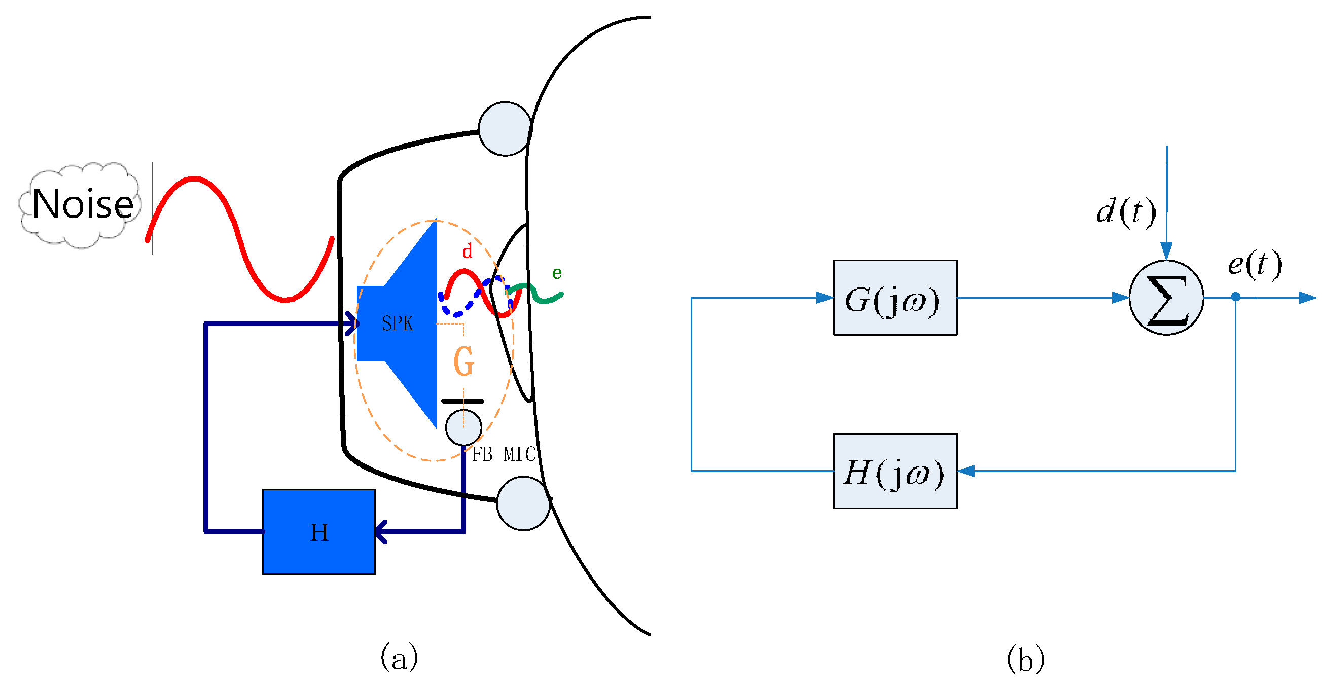
In Figure 1a, the secondary path G defined in the acoustic domain goes from the headphone speaker (SPK) to the feedback microphone (FB MIC) in the front cavity of the headphone, corresponding to the controller circuit H consisted of microphone preamplifier, feedback filter, and power amplifier in the electronic domain. The external noise passing through the headphone shell into the chamber is the primary noise d . After the controller is turned on, the remaining error noise is e . In Figure 1b, where d ( t ) and e ( t ) are the primary noise signal and error noise signal, respectively, G ( j ω ) and H ( j ω ) are the transfer functions of the secondary path and controller circuit in the complex frequency domain, respectively.
The system sensitivity function is defined as the transfer function between the primary noise signal and the error noise signal, as follows
S ( j ω ) = E ( j ω ) D ( j ω ) = 1 1 L ( j ω )
where L ( j ω ) = G ( j ω ) H ( j ω ) is the open-loop transfer function of the system. In addition, the complementary sensitivity function of the system is defined as follows
T ( j ω ) = 1 S ( j ω ) = L ( j ω ) 1 L ( j ω )
From the point of view of noise suppression, when the primary noise exists, the error signal picked up by the error microphone should be the smallest in terms of mean square.
E [ e 2 ( t ) ] = 1 π 0 Φ e ( ω ) = 1 π 0 | S ( j ω ) | 2 Φ d ( ω ) d ω = S ( j ω ) w 1 ( ω ) 2 2
where E [ ] represents the mathematical expectation, Φ e ( ω ) and Φ d ( ω ) are the power spectral densities of e ( t ) and d ( t ) , respectively.
The objective function and constraint of the H2/H∞ framework is set as follows
min [ S ( j ω ) w 1 ( ω ) 2 2 ]
S ( j ω ) w 2 ( ω ) < 1
where w 1 ( ω ) is the root mean square value of the power spectral density of primary noise, and w 2 ( ω ) is the limit of noise lift at each frequency.
From the perspective of system stability, an open-loop transfer function should have a certain Amplitude Margin, defined as L AM , and Phase Margin, defined as L PM . The stability constraint of the feedback system is set as follows
L AM = 10 ( 10 / 20 ) L PM = π / 6
For an invariable specified secondary path, the above objective function and constraints, defined as Method 1, can ensure that the system can achieve a good balance between noise reduction and waterbed lift, but the secondary path in a real system has uncertainties, so it is necessary to add uncertainty constraint.

2.3. Secondary Path Uncertainty Constraint

The uncertainty discussed in this paper is described by multiplicative uncertainty. The multiplicative form of the secondary path can be expressed as
G ( j ω ) = G 0 ( j ω ) [ 1 + Δ ( j ω ) ]
where G 0 ( j ω ) is the initial secondary path transfer function, and the expectation of Δ ( j ω ) represents the degree of multiplicative uncertainty:
E [ Δ ( j ω ) ] = E [ G ( j ω ) G 0 ( j ω ) 1 ] = E [ G ( j ω ) ] G 0 ( j ω ) 1
From a statistical point of view, the degree of uncertainty is minimal when the initial secondary path G 0 ( j ω ) is exactly the expected value of the secondary path E [ G ( j ω ) ] . In practical applications, we should test as many secondary path transfer functions as possible to improve the scope of system stability. In case of limited numbers of measurement, using the mean value of the secondary path transfer function obtained from all tests helps to reduce the degree of system uncertainty.
In order to ensure the stability of the system in each actual scenario, set w 3 ( ω ) as the greatest degree of uncertainty Δ ( j ω ) , and because the measured data are always limited, a safety factor δ (where 0 < δ < 1 ) is set to improve the robustness of the system stability to uncertainty. The larger is the number of test samples, the closer δ is to 1. The weighting coefficient of uncertainty constraint is denoted as w 3 ( ω ) / δ .
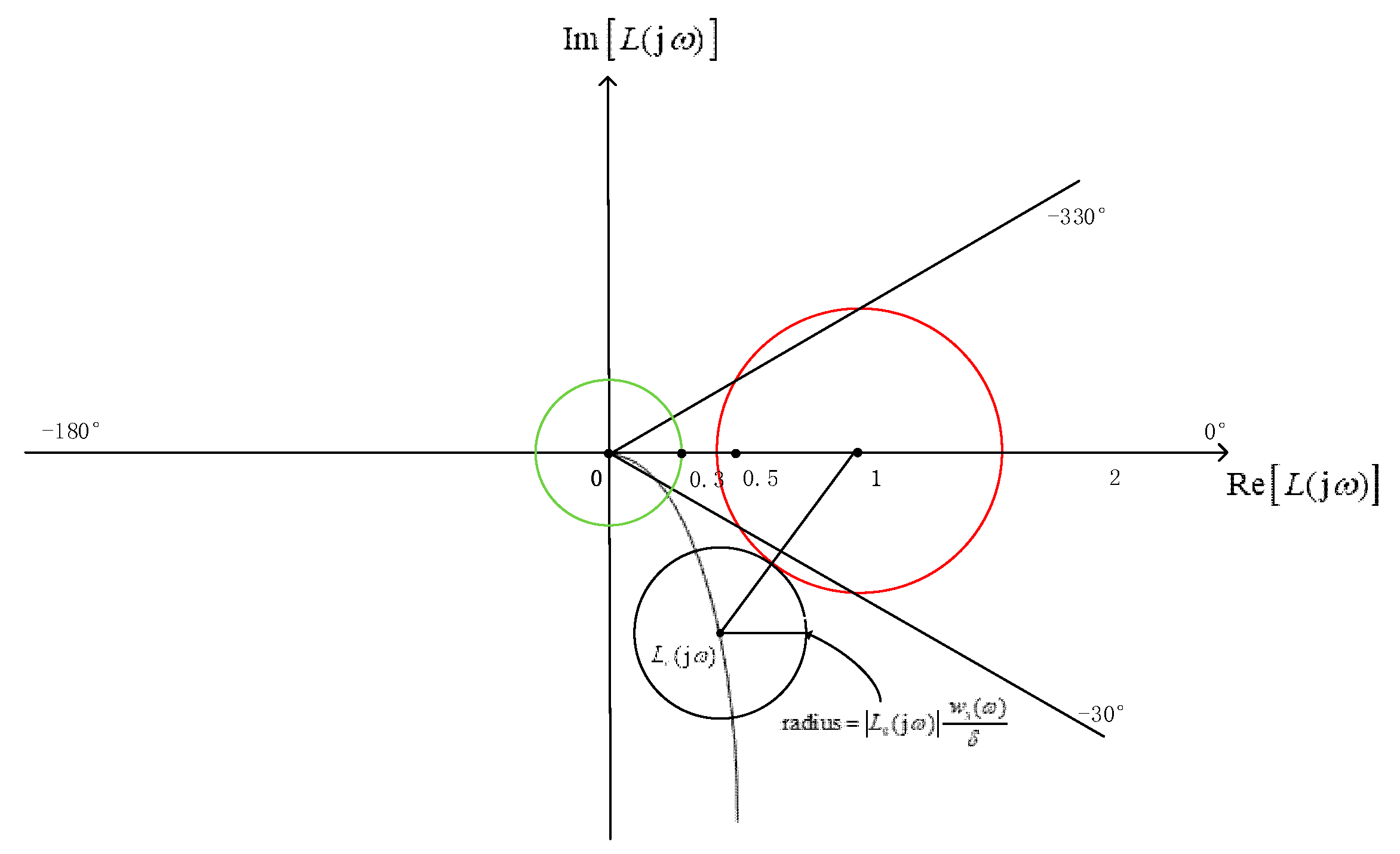
As shown in Figure 2, the open-loop transfer function is restricted to the disk whose center is the open-loop transfer function L 0 ( j ω ) and whose radius is | L 0 ( j ω ) w 3 ( ω ) / δ | , resulting from the fluctuation of the secondary path transfer function. The Nyquist stability condition requires that all points in the disk do not pass through the point ( 1 , j 0 ) , and the radius | L 0 ( j ω ) w 3 ( ω ) / δ | is less than the distance | L 0 ( j ω ) 1 | between the center L 0 ( j ω ) and ( 1 , j 0 ) .
| L 0 ( j ω ) w 3 ( ω ) / δ | | L 0 ( j ω ) 1 | < 1
In the Nyquist plot, noise rising is more than   1 / χ in the red disk with center ( 1 , j 0 ) and radius χ , which is defined as the waterbed suppressing factor. The open-loop transfer function is restricted in the black disk. When these two disks are dis-intersected, the noise rising caused by uncertainty is less than   1 / χ , and hence an uncertainty constraint is proposed as below:
| L 0 ( j ω ) w 3 ( ω ) / δ | | L 0 ( j ω ) 1 | χ < 1
Equation (14) considers the constraint conditions of secondary path uncertainty. In order to prevent the bandwidth of noise reduction being too narrow, χ should be less than w 2 ( ω ) . When χ = 0 , the constraint has only met the Nyquist stability but not limit the waterbed lift for the secondary path uncertainty.

2.4. Control Strategic Function

Use a specified measured secondary path transfer function and a feedback controller with parameter vector X 1 to build a feedback control strategic function. This procedure is denoted as Method 1,
J 1 ( X 1 ) = S ( X 1 ) w 1 ( ω ) 2 2 + γ 1 { U [ | L ( X 1 ) | L AM ] + U [ L PM | phase ( L ( X 1 ) | ) ] } + γ 2 U [ w 2 ( ω ) S ( X 1 ) 1 ]
Considering the uncertainty of the secondary path, use the mean of multiple measured secondary path transfer functions and a feedback controller with parameter vector X 2 to rebuild the feedback control strategic function with the uncertainty constraint. This procedure is denoted as method 2,
J 2 ( X 2 ) = S 0 ( X 2 ) w 1 ( ω ) 2 2 + γ 1 { U [ | L 0 ( X 2 ) | L AM ] + U [ L PM | phase ( L 0 ( X 2 ) | ) ] } + γ 2 U [ w 2 ( ω ) S 0 ( X 2 ) 1 ] + γ 3 U [ | L 0 ( X 2 ) w 3 ( ω ) / δ | | L 0 ( X 2 ) 1 | χ 1 ]
where, U ( x ) is the unit step function
U ( x ) = { 1 x 0 0 x < 0
In Equation (16), the first term on the right side represents the amplitude of the sensitivity function, indicating the noise reduction performance. It reaches the minimum when the noise reduction is equal to the frequency characteristic of primary noise w 1 ( ω ) , and the best feedback reduction is achieved.
The second term on the right side of Equation (16) represents the constraint on the Nyquist stability. If the open-loop function does not meet the conditions regarding amplitude margin L AM or phase margin L PM , this term is multiplied by a penalty factor γ 1 , which is a positive real number.
The third term pertains to the constraint on waterbed lift of the mean of second paths. If the noise enhancement exceeds a preset upper limit   1 / w 2 ( ω ) , this term is also multiplied by another positive real number penalty factor γ 2 .
The fourth term relates to the uncertainty constraint of the secondary path. If the constraint is broken through, this term is multiplied by a positive real number penalty factor γ 3 . If a single specified secondary path design is used, this term of the strategic function is omitted.
In this study, the IGWO algorithm is used to solve the control strategic function. The initial parameter range can be customly set based on experience, thus offering good performance in terms of solution accuracy and convergence speed. It is suggested that the optimization process should be repeated for multiple times to find the global optimized filter coefficients.
3. Simulation and Experimental Validation

3.1. Test Setting

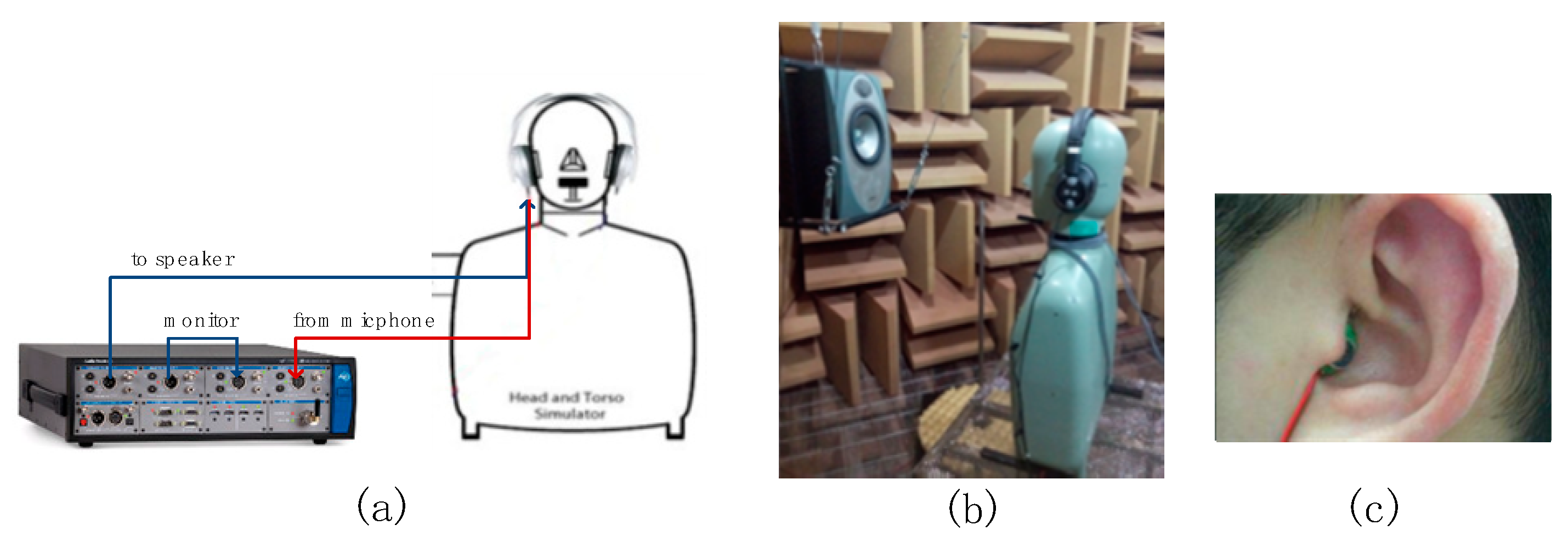
In this section, experiments are conducted using ANC headphones designed by Goertek to validate the proposed method. The secondary path transfer function test is shown in Figure 3), using Audio Precision 525 (AP525) as the measuring device. The ANC test experimental environment is shown in Figure 3b. The experiment is conducted in an anechoic room with a low frequency cut-off frequency of 80Hz and free field radius of 1m. The noise source is generated by a Tannoy's Precision6 speaker, which has an effective frequency response range of 60Hz to 50kHz. A B&K 4128 dummy Head and Torso (HATS) is used as the headphone wearing and sound recording device. The headphone is worn on the HATS facing the test speaker, and the distance between the test speaker and the HATS is 0.5m. The real person ANC test is also conducted and a microphone is placed at the ear canal to collect the residual noise, as shown in Figure 3c. A controller with the ADAU1777 as its core component is adopted to implement the feedback controller. The sampling frequency of ADAU1777 is configured to be 768kHz, and the system latency from ADC to DSP and then to DAC is 4.7μs, which can be ignored.
During the secondary path transfer function test, the AP525's left output is connected to the speaker of the headphone, and the right input is connected to the error microphone of the headphone. The left input is directly connected to the right output to offset the delay caused by the device's own ADC and DAC. The secondary path transfer function is tested using the steady-state noise signals.
As current commercial ANC headphones use the proximity sensor to detect if the headphone is worn, this experiment only focuses on the wearing state of headphone. However, the proximity sensor cannot distinguish between squeezed wearing and normal wearing states, so it is necessary to conduct the headphone squeeze scenario test. During the test, the headphone is worn in normal and simulated squeeze state alternatively. In the latter state, the headphone is tightened with a rubber band and the strength of the rubber band is adjusted until the headphone cushion has been squished. In order to increase the samples of secondary path, four real subjects and HATS substitute test are conducted under the same experimental conditions. The four subjects have head circumference of 52.8 to 59.1cm. They are two men and two women: one man and woman wear glasses, and the subjects with long hair have the hair pressed when wearing headphones. The parameters of the subjects are shown in Table 2.
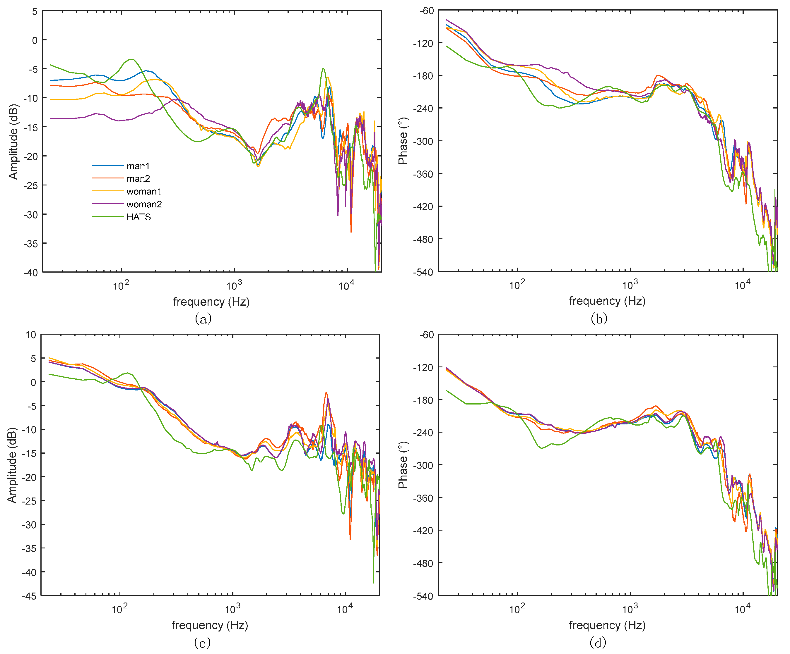
During the test, the headphone is adjusted to fit the wearing state of each subject (both HTAS and human subjects) headphone in the anechoic room for the first round of test, and then the strength of the rubber band is adjusted to make the headphone squished for the second round of test. In each round of test, the headphone is kept still for three times on each subject and the average value is recorded. The test results are shown in Figure 4a,b, displaying the amplitude and phase response of the secondary path transfer function, respectively under the normal wearing state of the first round. In general, large difference is present in the low frequency range and the results of male subjects have larger low-frequency amplitude than those of female, since man’s head circumference is larger and the headphone is easier to be squeezed and sealed on them. Air leakage may be created when the headphone presses glasses legs or long hair, resulting in low-frequency attenuation. In Figure 4c,d the results are shown of the second round with squished wearing of headphone. In general, the headphone is almost sealed, so the amplitude difference is smaller in the low frequency range. The test results of the HATS in both rounds (green line) demonstrate more pronounced rise and dip caused by high-frequency reflections because the hardness of HATS is different from that of human subjects.
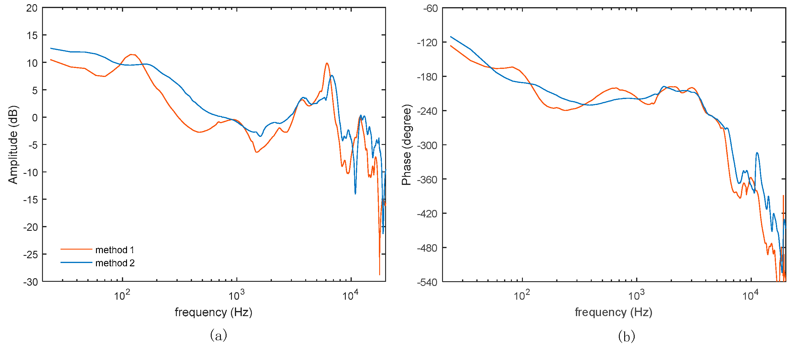
The measured secondary path results show fluctuation across different subjects, likely causing system stability risk if designed with a specified secondary path. To verify this, two optimization methods are proposed: the first method uses a normal wearing test result on the HATS as the specified secondary path transfer function; in the second method, the mean of all test results is used as the secondary path transfer function. The secondary path transfer functions used in both methods are shown below.

3.2. Controller Optimization and Validation

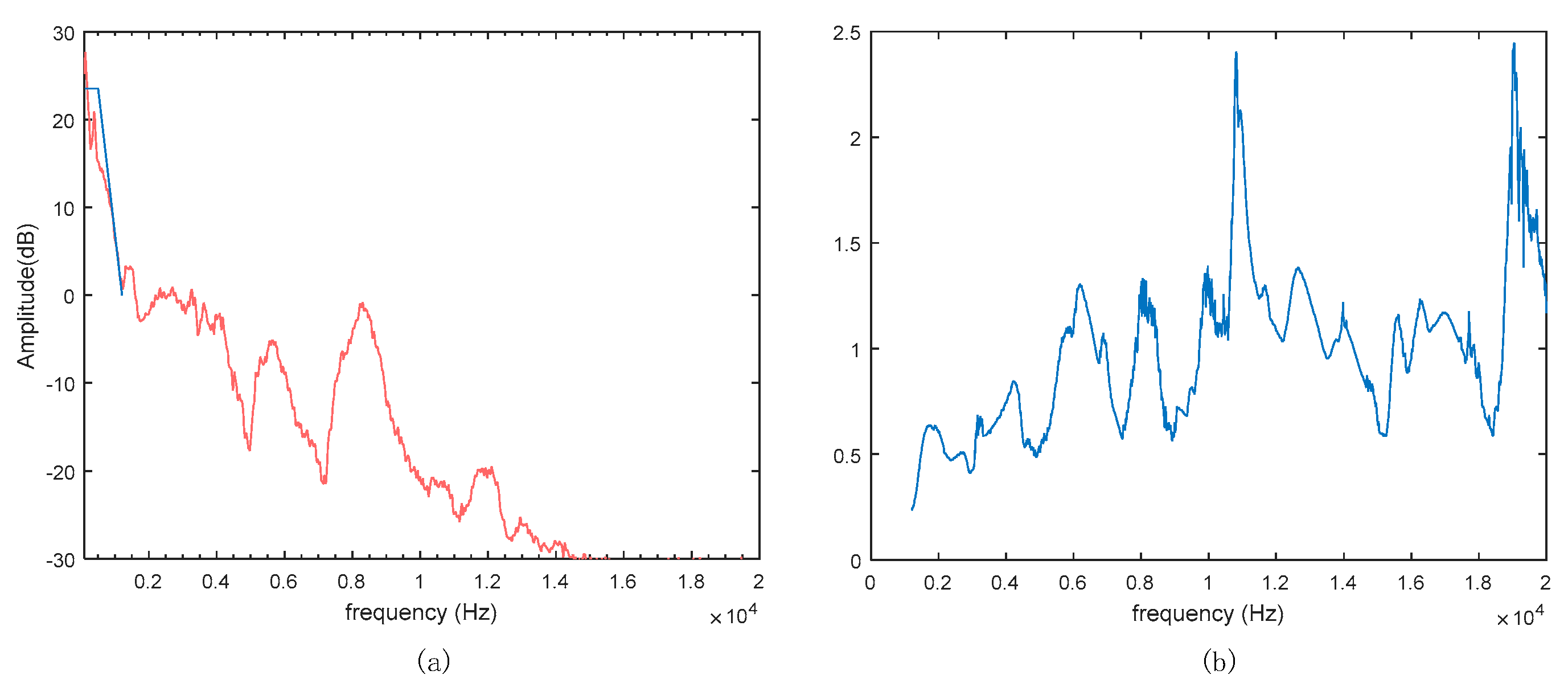
Firstly, for frequency discretization, the sampling rate is set to be 40kHz, corresponding to 512 frequency points in the frequency domain. Set the weighting coefficient w 1 ( ω ) to be 15 from 117.2Hz to 390.6Hz and 1 for 39.1Hz and 1.21kHz, and the values at the remaining frequency points are obtained by discretized frequency interpolation. It is shown in dB by the blue curve in Figure 6a. The weighting coefficient w 2 ( ω ) is given a fixed value 10 ( 3 / 20 ) from 1.21kHz to 20kHz. For method 2, the weighting coefficient w 3 ( ω ) is calculated by all the measured secondary path transfer functions, and is shown in Figure 6b. The safety factor δ is set to be 0.9 and the waterbed suppressing factor χ is set to be 10 ( 5 / 20 ) . The penalty factors are set to be the same: γ 1 = γ 2 = γ 3 = 10000 , for simplifying the optimization.
For a cascaded IIR controller, the function of H 1 is to achieve more noise reduction at low frequencies, H 2 , H 3 and H 4 are used to process the waterbed effect in the middle frequency band, and H 5 ensures the stability of the ultra-high frequency band above 10kHz. The upper and lower limits of the filter parameters ub and lb are configured in Table 3 according to the author's experience. In the IGWO algorithm, the population size is set to be 50, dimension 16, iteration times 10000, and the optimization process is repeated 100 times to obtain the global optimal solution. The filter parameters calculated by the two methods are shown in Table 3. The controller responses of the two methods are shown in Figure 7.
Next, in addition to the HATS and 4 subjects on whom the secondary path transfer functions have been tested, 4 additional subjects are added for the secondary path and noise reduction test, and their parameters are shown in Table 3.
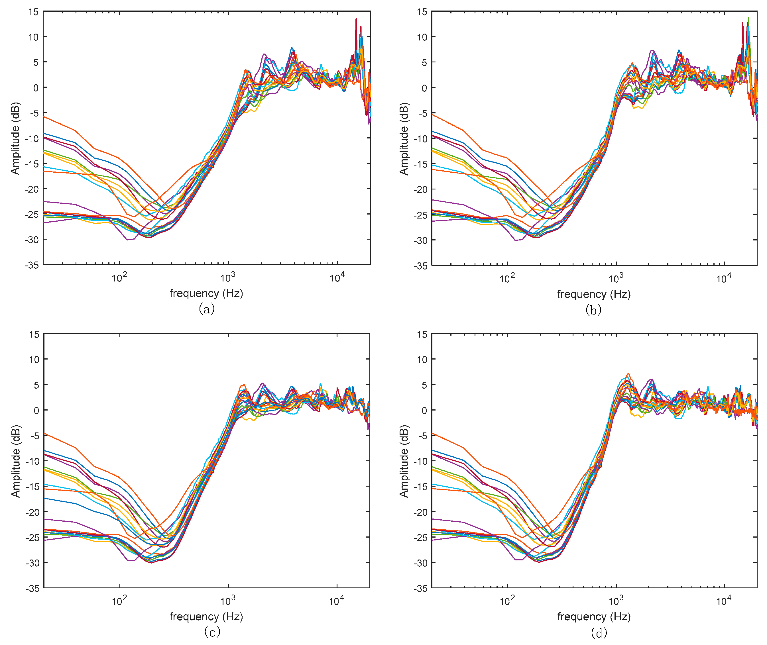
Noise reduction is simulated for all the measured secondary path transfer functions, with the controllers optimized by method 1 and method 2, and the results are shown in Figure 8a and Figure 8c, respectively. The simulated results shown in Figure 8a suggest that method 1 will have relatively serious waterbed effect and stability risk at high frequencies, while the results in Figure 8c) suggest that method 2 will have relatively mild waterbed lift (controlled within 5dB) under all measured secondary paths. Subsequently, the noise reduction is also measured with the controllers optimized by method 1 and method 2 and the results are shown in Figure 8b and d, respectively. The measured results are highly consistent with the corresponding simulated results.

4. Conclusions

In this paper, an uncertainty constraint is proposed based on multiple measured secondary path transfer functions obtained from different subjects and dummy head in different wearing states. It includes a safety factor, which is used to make the secondary path transfer function obtained from a limited number of subjects compatible with more subjects, and a waterbed suppressing factor, which is introduced to limit the waterbed lift. With the aid of this constraint, the optimal parameters of feedback controller composed of cascade biquad IIR filters are found with the IGWO algorithm, and experiments are also conducted in an anechoic room. The experimental results are in good agreement with the simulation results, and both demonstrate that the optimal controller has better noise reduction performance. The measured results also suggest that the proposed method ensures stability and mild waterbed lift for new subjects without a priori data.

Author Contributions

Conceptualization, Y.H.; methodology, Y.H.; software, Y.H.; validation, Y.H.; formal analysis, Y.H.; investigation, Y.H.; data curation, Y.H.; writing—original draft preparation, Y.H.; writing—review and editing, L.P.; supervision, L.P. All authors have read and agreed to the published version of the manuscript

Data Availability Statement

The data presented in this study are available on request from the corresponding author

Conflicts of Interest

The authors declare no conflict of interest.

References

  1. Yang, J.; Wu, M.; Han, L. A review of sound field control. Appl. Sci. 2022, 12, 7319. [Google Scholar] [CrossRef]
  2. Bai, M.R.; Pan, W.; Chen, H. Active feedforward noise control and signal tracking of headsets: Electroacoustic analysis and system implementation. J. Acoust. Soc. Am. 2018, 143, 1613–1622. [Google Scholar] [CrossRef] [PubMed]
  3. Nelson, P.A.; Elliott, S.J. Active Control of Sound; Academic Press: London, UK, 1992. [Google Scholar]
  4. Elliott, S.J. Signal Processing for Active Control; Academic Press: London, UK, 2001. [Google Scholar]
  5. Boucher, C.C.; Elliott, S.J.; Nelson, P.A. The effects of modeling errors on the performance and stability of active noise control systems. in Proc. Proceedings of Recent Advances in Active Control of Sound Vibration. 1991; 290–301. [Google Scholar]
  6. Zhou, K.; Doyle, J.C.; Glover, K. Robust and optimal control; Prentice hall: New Jersey, 1996. [Google Scholar]
  7. Rafaely, B. Active noise reducing headset-an overview. in INTERNOISE and NOISE-CON Congress and Conference Proceedings, The Hague, the Netherlands. (27–30 August 2001), 2144–2153.
  8. Bai, M.R.; Lee, D. Implementation of an active headset by using the H∞ robust control theory. J. Acoust. Soc. Am. 1997, 102, 2184–2190. [Google Scholar] [CrossRef] [PubMed]
  9. Pawelczyk, M. Analogue active noise control. Appl. Acoust. 2002, 63, 1193–1213. [Google Scholar] [CrossRef]
  10. Yu, S.H.; Hu, J.S. Controller design for active noise cancellation headphones using experimental raw data. IEEE/ASME Transactions on Mechatronics. 2002, 6, 483–490. [Google Scholar]
  11. Liang, K.W.; Hu, J.S. An open-loop pole–zero placement method for active noise control headphones. IEEE Transactions on Control Systems Technology. 2016, 25, 1278–1283. [Google Scholar] [CrossRef]
  12. Moon, S.P.; Chang, T.G. The Derivation of the Stability Bound of the Feedback ANC System That Has an Error in the Estimated Secondary Path Model. Appl. Sci. 2018, 8, 210. [Google Scholar] [CrossRef]
  13. Eriksson, L.J.; Allie, M.C. Use of random noise for on-line transducer modeling in an adaptive active attenuation system. J. Acoust. Soc. Am. 1989, 85, 797–802. [Google Scholar] [CrossRef]
  14. Morgan, D.R. A Note on ‘A Secondary Path Modeling Technique for Active Noise Control Systems’. IEEE Trans. on Speech Audio Processing. 1999, 7, 601–602. [Google Scholar] [CrossRef]
  15. Gan, W.S.; Kuo, S.M. An integrated audio and active noise control headsets. IEEE Trans. Consum. Electron. 2002, 48, 242–247. [Google Scholar] [CrossRef]
  16. Yang, T.; Hu, L.; Li, X.; Pang, L. An online secondary path modeling method with regularized step size and self-tuning power scheduling. J. Acoust. Soc. Am. 2018, 143, 1076–1084. [Google Scholar] [CrossRef] [PubMed]
  17. Seiler, P.; Packard, A.; Gahinet, P. An introduction to disk margins [lecture notes]. IEEE Control Systems Magazine. 2020, 40, 78–95. [Google Scholar] [CrossRef]
  18. Zhao, J.; Xu, J.; Li, X.D.; Tian, J. Performance optimization of an active noise reduction Headset. In Proceedings of the Inter-Noise 2005, Rio de Janeiro, Brazil, 7-10 August 2005; pp. 222–226. [Google Scholar]
  19. Guldenschuh, M.; Callafon, R. Detection of secondary-path irregularities in active noise control headphones. IEEE/ACM Transactions on Audio, Speech, and Language Processing. 2014, 22, 1148–1157. [Google Scholar] [CrossRef]
  20. Krishnamurthy, N.; Mansour, M.; Cole, R. Implementation challenges for feedback active noise cancellation. in 2012 IEEE International Conference on Acoustics, Speech and Signal Processing (ICASSP). 2012; 1649–1652. [Google Scholar]
  21. Benois, P.R.; Zolzer, U. Psychoacoustic optimization of a feedback controller for active noise cancelling headphones. In Proceedings of the 26th International Congress on Sound and Vibration (ICSV), Montreal, Canada, 7-11 July 2019. [Google Scholar]
  22. Hilgemann, F.; Jax, P. Robust Feedback Active Noise Control in Headphones Based on a Data-Driven Uncertainty Model. International Workshop on Acoustic Signal Enhancement (IWAENC). 2022. [Google Scholar]
  23. Wang, J.; Zhang, J.; Xu, J.; Zheng, C.; Li, X. An optimization framework for designing robust cascade biquad feedback controllers on active noise cancellation headphones. Appl. Acoust. 2021, 179, 108081. [Google Scholar] [CrossRef]
  24. An, F.; Wu, Q.; Liu, B. Feedback Controller Optimization for Active Noise Control Headphones Considering Frequency Response Mismatch between Microphone and Human Ear. Appl. Sci. 2022, 12, 977. [Google Scholar] [CrossRef]
  25. Storn, R.; Price, K. Differential evolution–a simple and efficient heuristic for global optimization over continuous spaces. Journal of global optimization. 1997, 11, 341–359. [Google Scholar] [CrossRef]
  26. Mirjalili, S.; Mirjalili, S.M.; Lewis, A. Grey wolf optimizer. Advances in Engineering Software. 2014, 69, 46–61. [Google Scholar] [CrossRef]
  27. Nadimi-Shahraki, M.H.; Taghian, S.; Mirjalili, S. An improved grey wolf optimizer for solving engineering problems. Expert Systems with Applications. 2021, 166, 113917. [Google Scholar] [CrossRef]
  28. Bristow-Johnson, R. Cookbook formulae for audio equalizer biquad filter coefficients. Cookbook formulae for audio equalizer biquad filter coefficients. Available online: https://webaudio.github.io/Audio-EQ-Cookbook/audio-eq-cookbook.html.
  29. BOSE. On-head detection uses sensors to identify when you’re wearing the headphones. Available online: https://assets.bose.com/content/dam/Bose_DAM/Web/consumer_electronics/global/products/headphones/QCUH-HEADPHONEARN/pdf/884885_OG_QCUH-HEADPHONEARN_en.pdf.
  30. SONY. Operations cannot be performed when the headset is removed. Available online: https://helpguide.sony.net/mdr/wh1000xm4/v1/en/contents/TP0002928786.html.
  31. Bloom, D.R. Automate Left/Right earpiece determination. US Patent No. 2019/0238963.
Figure 1. (a) Schematic drawing of feedback control headphone; (b) Block diagram of feedback system.
Preprints 98194 g001
Figure 2. Nyquist plot for system uncertainty.
Preprints 98194 g002
Figure 3. (a) Test setting for secondary path; (b) ANC test environment; (c) Microphone in the ear of subject for ANC test.
Preprints 98194 g003
Figure 4. Tested secondary path transfer function.
Preprints 98194 g004
Figure 5. Secondary path transfer functions used in the two methods.
Preprints 98194 g005
Figure 6. (a)Primary noise spectrum, red curve; weighting coefficient d b [ w 1 ( ω ) ] ,blue curve; (b) weighting coefficient w 3 ( w ) .
Preprints 98194 g006
Figure 7. (a) Amplitude response of controller; (b) Phase response of controller.
Preprints 98194 g007
Figure 8. Simulated and tested noise reduction: (a)(b) for method1; (c)(d) for method2.
Preprints 98194 g008
Table 1. Parameters of biquad IIR filter.
Coefficients Peaking High-shelf
b 2 1 α A 1 + α A A ( A + 1 ) + ( A 1 ) cos ( ω c ) 2 α A ( A + 1 ) ( A 1 ) cos ( ω c ) + 2 α A
b 1 2 cos ( ω c ) 1 + α A 2 A ( A 1 ) + ( A + 1 ) cos ( ω c ) ( A + 1 ) ( A 1 ) cos ( ω c ) + 2 α A
b 0 1 + α A 1 + α / A A ( A + 1 ) + ( A 1 ) cos ( ω c ) + 2 α A ( A + 1 ) ( A 1 ) cos ( ω c ) + 2 α A
a 2 1 α / A 1 + α / A ( A + 1 ) ( A 1 ) cos ( ω c ) 2 α A ( A + 1 ) ( A 1 ) cos ( ω c ) + 2 α A
a 1 2 cos ( ω c ) 1 + α / A 2 ( A 1 ) ( A + 1 ) cos ( ω c ) ( A + 1 ) ( A 1 ) cos ( ω c ) + 2 α A
a 0 1 1
Table 2. Parameter of subjects.
head circumference (cm) subject wear glasses Headphone press the hair
Man 1 59.1 No No
Man 2 58.1 Yes No
Woman 1 56.5 No Yes
Woman 2 52.8 Yes Yes
Table 3. Parameters of the controller.
filter parameters lb ub Method1 Method 2
H 1 peaking F c 1 (Hz)
Q 1
g 1 (dB)
100
0.3
10
400
2
20
351.56
0.31
14.48
312.50
0.40
16.45
H 2 peaking F c 2 (Hz)
Q 2
g 2 (dB)
4k
0.3
-30
10k
3
-10
6.60k
0.60
-24.32
4.22k
0.47
-14.06
H 3 peaking F c 3 (Hz)
Q 3
g 3 (dB)
2k
0.3
-10
7k
5
0
5.94k
3.99
-4.00
5.70k
1.06
-5.05
H 4 high-shelf F c 4 (Hz)
Q 4
g 4 (dB)
2k
0.3
-10
7k
5
10
4.26k
1.55
2.78
5.63k
2.98
-2.83
H 5 peaking F c 5 (Hz)
Q 5
g 5 (dB)
11k
0.3
-20
19k
2
0
13.0k
0.70
-7.04
15.0k
0.50
-9.02
g total 0.0 10 5.53 5.42
Table 4. Parameter of new subjects.
head circumference (cm) subject wear glasses Headphone press the hair
Man 3 59.6 No Yes
Man 4 57.3 No No
Woman 3 54.4 Yes Yes
Woman 4 57.1 No No
Disclaimer/Publisher’s Note: The statements, opinions and data contained in all publications are solely those of the individual author(s) and contributor(s) and not of MDPI and/or the editor(s). MDPI and/or the editor(s) disclaim responsibility for any injury to people or property resulting from any ideas, methods, instructions or products referred to in the content.
Copyright: This open access article is published under a Creative Commons CC BY 4.0 license, which permit the free download, distribution, and reuse, provided that the author and preprint are cited in any reuse.
Prerpints.org logo

Preprints.org is a free preprint server supported by MDPI in Basel, Switzerland.

Subscribe

© 2024 MDPI (Basel, Switzerland) unless otherwise stated