1. Introduction
In recent years, multimedia and communications industry have developed rapidly. Many large streams of multimedia data is transmitted over an insecure channel. As the rate of hacking increased with the passage of time, therefore, the security of the data must be increased day by day [
1]. Numerous algorithms are developed in the world that are efficient and robust, but are still not sufficient to protect data. In addition, less computationally complex algorithms are required to cater the need to secure high speed data transmissions. A lossless, novel and secure image encryption algorithm based on the modified chaotic logistic map (CLM) that takes less computational time for encryption is presented in this research.
The CLM has many great features such as sensitive dependence on initial conditions, random orbit, pseudorandomness, good ergodicity, better cross-correlation properties, high efficiency, better mixing properties and large keyspace. These features makes CLM a potential candidate in quantum image encryption algorithms [
2,
3,
4]. Therefore CLM is also quantum safe. CLM also has low computational cost and it takes less hardware and it is easy to implement [
5]. It is verified that CLM provides high speed with low cost [
6].
A good encryption scheme must have a substitution-permutation (SP) network as indicated by C. E. Shanon [
7] to increase its security [
8]. The pixel level substitution and permutation is used in the algorithm to save computation time and cost. Otherwise, if bit level substitution and permutation is used then the algorithm’s computation time and cost will increase eight times.
Permutation is the property used for the rearrangement of pixels in some pseudorandom order. It means that several pixels of the encrypted image are affected by just changing one pixel of the original image. Therefore, it hides any dependency between the input image and the encrypted image [
9]. Any algorithm is more resistant to frequency analysis attacks by using permutation techniques. The permutation techniques are further classifieed into two categories, one is pixel level permutation and the second is bit level permutation. These permutations are achieved by employing various transforms [
10,
11], chaotic maps [
12,
13,
14,
15,
16,
17], cyclic shifts [
18,
19,
20,
21], hash functions [
22], sorting techniques [
15,
23,
24,
25,
26,
27] and parallel computing [
28]. Although, these transformational techniques based algorithms have many flaws, one of them is that they create high security but increases time complexity which further results in lengthy preprocessing and poor permutation performance. On the other hand, sorting based permutation techiniques gives the best permutation effect but the time complexity will be increased and memory cost will be high. if cyclic shift permutation techniques are utilized, they reduce the computational complexity and therefore reducing memory costs, but weaken the permutation effect. So, there is a need for a secure encryption algorithm which reduces the time complexity and memory cost but not at the cost of reduction in the security.
Substitution is used to obscure the connection between the corresponding pixels of the input image and the encrypted image. This property of substitution makes it ideal to hide the connection between the secret key and the encrypted image. Substitution is also subdivided into pixel level substitution [
10,
11,
12,
13,
14,
15,
16,
17,
24,
25,
26,
27,
29,
30,
31,
32] and bit level substitution [
18,
23,
33,
34]. In bit level substitution, the substitution can be lengthy and thus time consuming. Therefore in the proposed algorithm, pixel level substitution is used.
Image encryption can be lossy or lossless [
35]. Various transformation techniques used for image encryption are lossy [
10,
11]. In the proposed algorithm, we employ CLM because of its high dependency towards initial conditions. Therefore, we achieved lossless encryption. A novel and secure image encryption algorithm based on CLM that requires less computational time to encrypt an original image is presented. Shannon’s idea of using substitution-permutation and one-time-pad network to achieve ideal secrecy is the backbone of this research [
7].
The organization of rest of the paper is as follows: The proposed image encryption algorithm is presented in
Section 2. The results alongwith statistical tests are presented in
Section 3. The conclusion of the research is presented in
Section 4.
2. Proposed Algorithm
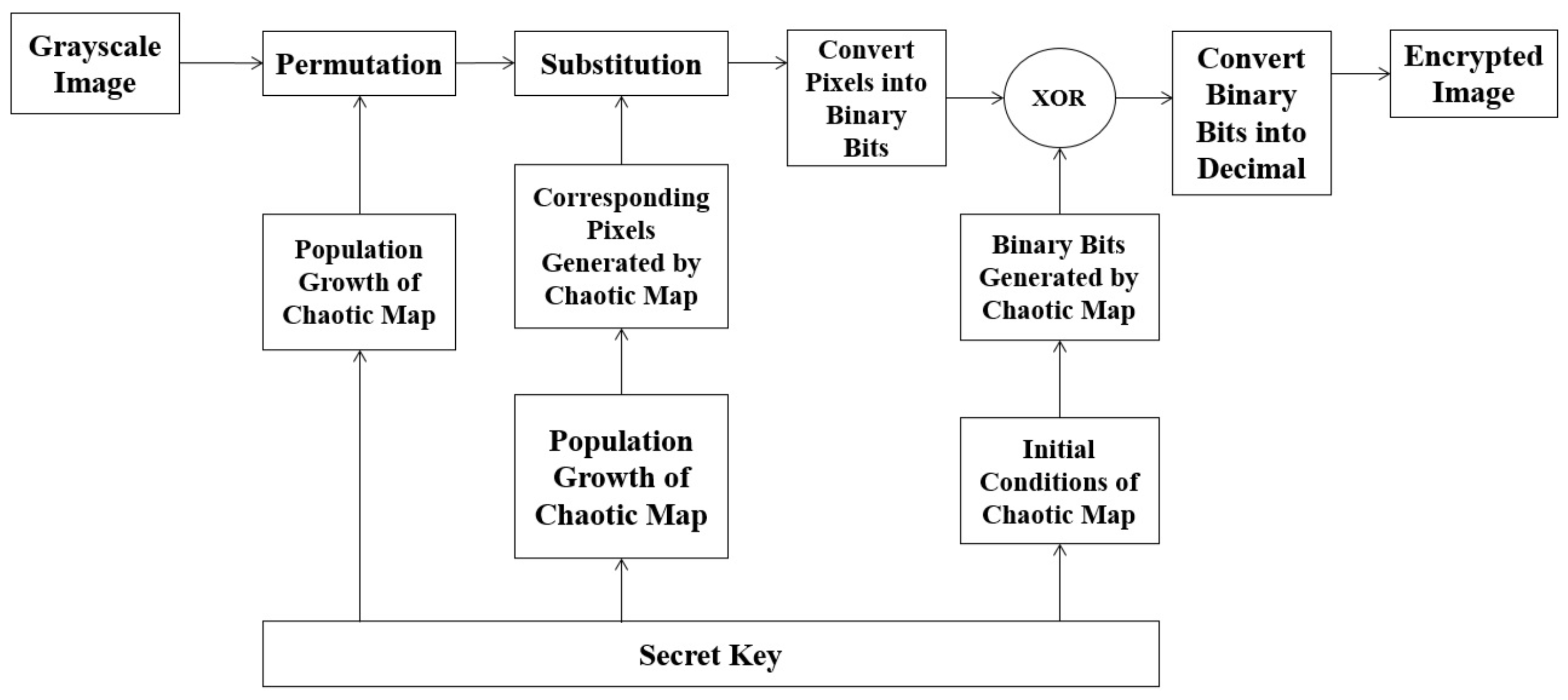
The encryption process is divided into six stages. The block diagram is given in
Figure 1. In the first stage, the permutations on the grayscale image is performed. The second stage involves the substitution of pixel intensities of the permuted grayscale image. The pixel intensities are then converted into binary bits in the third stage. In the fourth stage, the random binary bits are collected from the CLM. In the fifth stage, the binary bits from stage three and four are added using an “XOR” operation. In the last and final stage, the resultant bits are converted in to pixel intensities. The details of the six stages are presented as follows:
2.1. Permutation
The permutation process rearranges pixel intensities according to a sequence acquired from CLM. For example, if a permutation matrix [2, 4, 1, 3] obtained from CLM with population growth, is applied to numbers (Pixel intensities), the resultant sequence after permutation is In an image, all the input pixels are shuffled in a random manner. In the proposed algorithm, the new rows and columns of the substituted image are computed by using CLM and its population growth is a part of its key.
2.1.1. Chaotic Logistic Map
The logistic map was first introduced by Robert May [
36]. The governing equation for the logistic map is:
where
is the population growth of the logistic map. The proposed algorithm presents a unique combination of 256 numbers that are required. Therefore, through extensive testing, it is determined that the numbers from
arranged in ascending order are permuted with the help of CLM. It is necessary for the population growth of the logistic map to be equal to
. Only on these values, we can achieve a unique and random combination of
numbers. Therefore, the equation is modified and can be written as:
where
is a set of positive integers in eq.
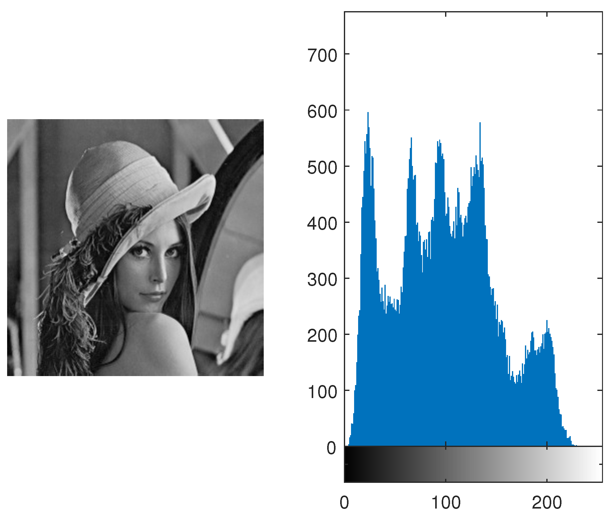
2. In this way, we permute the arrangement of rows and columns. Consider an image of Lena (
). (The image and histogram are shown in the
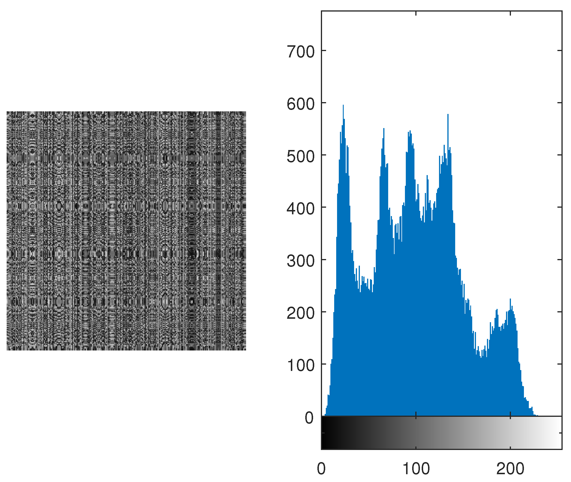
Figure 2.) Its permuted image and its histogram are shown in
Figure 3. It is evident from both histograms (which are identical) that pixels are shuffled in such a manner that the permuted image is not depicting any resemblance with the original image.
2.2. Substitution
The substitution is a process in encryption, where the bits from the original message are substituted with pseudorandom bits. It is used to obscure the relationship between the pixels of input image and the corresponding pixels of the encrypted image [
9]. Pixel intensities are used rather than bits to reduce computation time. Therefore, pixel intensities are substituted using enhanced version of CLM, which is explained in
Section 2.1.1.
The substituted pixels are shown in
Table 2 with population growth at
of CLM
In comparison to
Table 1 and
Table 2, pixel intensity 1 is substituted to pixel intensity 245. The permuted image of Lena is shown in
Figure 3, is substituted and its image and histogram are shown in
Figure 4. The histogram is not similar to uniform distribution, therefore, binary bits are added in the form of one-time pad and it is explained in the latter sections.
2.3. Binary Form of the Image
The data of pixel intensities is now converted as sequence of binary bits of 8-tuple. The range of pixel intensities is from 0 to 255. The pixel intensities from
Section 2.2 (each pixel intensity between 0 to 255 ) are now converted as sequence of binary bits of 8-tuple. In the latter section, it will be easier for us to add random binary bits in the pixel intensities to increase the randomness and consequently increasing the security of our proposed cryptosystem.
2.4. Bit Generation
It is a common misconception that one-time pad is breakable. It is contrary to that. If the key used in one-time pad is random and it is kept hidden from all possible hacks (attacks), then the only possible way to hack a one-time pad is only by brute force attack [
37].
In this attack, all possible combinations are applied. For Example, if the key consists of 2-bits, then the possible combinations are
. It means that for a two-bit key, hacker must enter the key four time. One of them is the actual key. In this way, brute force attack can occur. In general, if the key is
long then the combinations will be
. C. E. Shannon [
7] in his paper proves that ideal secrecy depends on the randomness of the key.
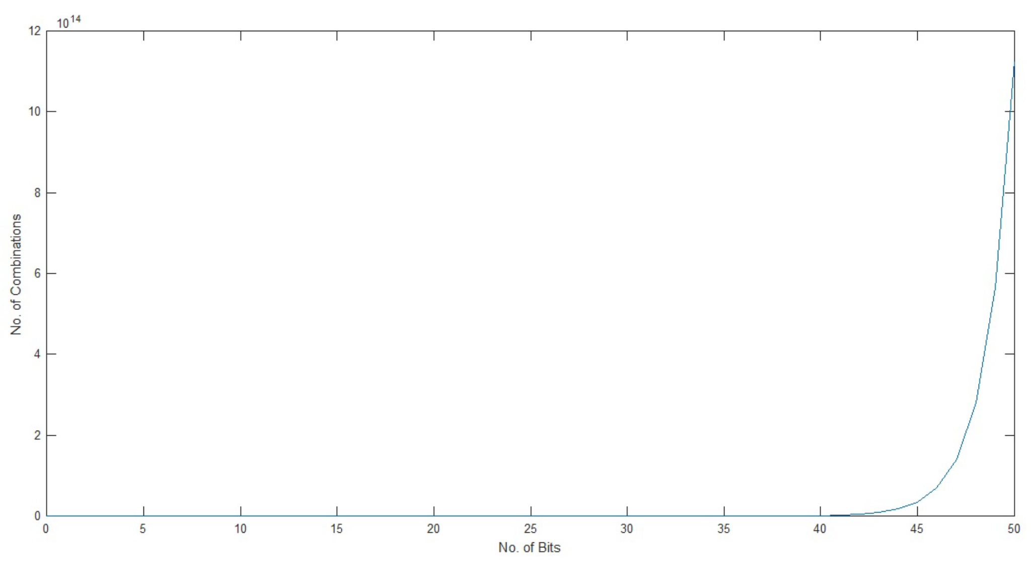
It is evident from the graph in
Figure 5 that if we increase the number of bits then the number of combinations will also increase exponentially. Therefore, the hacker must have to enter more and more combinations, if the key gets longer. The pseudorandom orbit of chaotic logistic map is very high. The secret key space, a chaotic logistic map can offer is more than
[
38]. The random binary bits are generated from the CLM.
2.5. XOR Operation
The binary of the pixel intensities and binary bits from CLM are added in the form of “XOR” operation. In the “XOR” operation same bits result in the output 0 and unlike bits give the output 1.
2.6. Conversion of Binary Bits to Encrypted Image
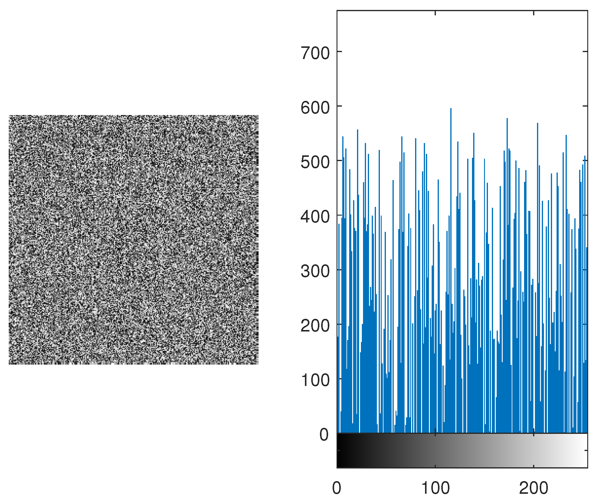
The resultant binary bits are then converted into pixel intensities. The acquired pixel intensities represent the encrypted image of Lena from the proposed algorithm. As an example, the substituted image of Lena shown in
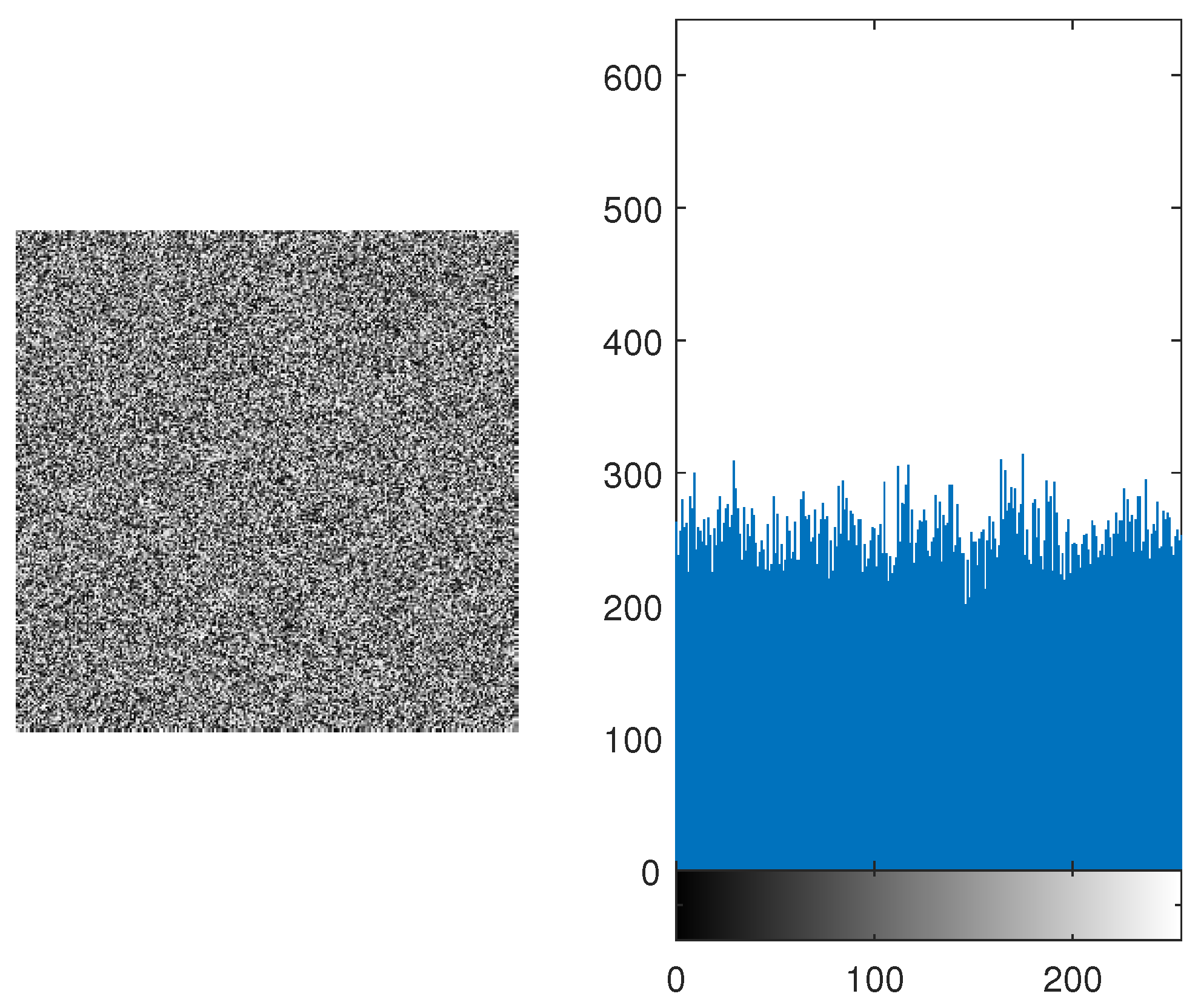
Figure 4 is then XORed. The encrypted image and its histogram are shown in
Figure 6. The histogram is resembles uniform distribution, as shown in
Figure 6.
3. Results
We perform numerous statistical tests on the proposed encryption algorithm. These statistical tests include: key space analysis, sensitivity analysis, strict avalanche criteria (SAC), histogram analysis, entropy analysis, mean of absolute deviation (MAD) analysis, correlation analysis, contrast analysis and homogeneity. The images used in the testing are taken from the University of Southern California - Signal and Image Processing Institute (USC - SIPI) database [
39].
3.1. Keyspace Analysis
It is a well-known fact that a large key space is essential for an encryption algorithm to be resistant against brute force attack [
40]. The proposed algorithm uses the key at four different stages. First, the key is broken into four parts. First two parts are used for permutation of the image. Its distinct combinations are
. The third part is used in the s-box for substitution. Its distinct combination are
. The fourth part is used in obtaining the random bits from the CLM. It ranges from
. Therefore, it accumulates a huge key space, resultantly increase the security of the encryption scheme.
3.2. Complexity Analysis
Complexity analysis is used to check how much memory and time is used to run a certain algorithm on a machine.
The permutation performance of the proposed algorithm is compared with some of the classical encryption algorithms as shown in
Table 3. The proposed algorithm shows best performance.
3.3. Sensitivity Analysis
The initial conditions of any algorithm play a key role in its security. Therefore, the security of the algorithm is dependent over its initial conditions. For this, two common measures are used, [
41,
42], i.e., the number of pixels change rate (NoPCR) and unified average pixel changing intensity (UAPCI) are used.
3.3.1. Number of Pixel Change Rate (NoPCR)
It is used to check how a minute change in the input image can affect the output image. For this purpose, an input image is acquired, only one-bit change is performed in it. In image processing, one-bit change means one intensity change in pixel value. The original input image and the one-bit changed image are processed through the algorithm, two separate ciphered images are acquired. After that, the following relationship is applied to both of the images.
where
Cipher Image of Input Image
Cipher Image of Input Image with one-bit change
Breadth of the Image
Height of the Image
x and y represents the positions of pixel in the horizontal and vertical direction respectively
In this manner, a percentage is computed to check how many pixels are change in both of the ciphered images i.e., between
and
. In this way, we are checking the security of our proposed algorithm. It is applied on various images, some of the results are given in
Table 4.
In
Table 4, it is evident that a one-bit change in the input image can result more than 99% change in the ciphered image.
3.3.2. Unified Average Pixel Changing Intensity (UAPCI)
In the previous subsection, the change in number of pixels is calculated for the entire image. In this subsection, we compute how much one pixel is changed according to its neighbouring pixel. A unified average value is computed for the whole image. First, two ciphered images are taken whose input image is changed in one-bit.
where
Cipher Image of Input Image
Cipher Image of Input Image with one-bit change
Breadth of the Image
Height of the Image
x and y represents the positions of pixel in the horizontal and vertical direction respectively
In
Table 5, UAPCI of various images with different image sizes along with one-bit change in input image are given. It is proved from the table that an average of 7% change is occurring from pixel to pixel if a one-bit change occurred in the input image. These two measures show us that our proposed algorithm is dependent on input image. If any hacker tries to change one-bit value in the system, it can easily be identified.
3.4. Strict Avalanche Criteria (SAC)
It is performed to check the algorithm’s dependency over its initial conditions. It is performed in such a manner that one bit in
creates more than 50% change in
. A function
exhibits the avalanche effect if and only if
where
3.5. Histogram Analysis
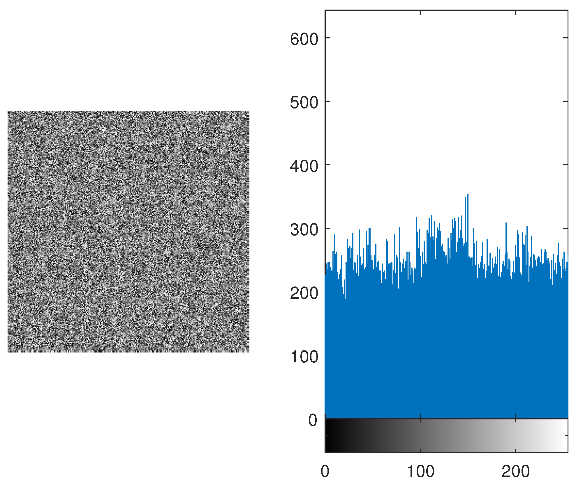
It is performed to check whether the encrypted image represent any resemblance towards the original image or not. If the histogram of the image is equiprobable than it is hard for the attackers to know which original image was transmitted. Equal distribution gives no clue to the hackers and it increases the security of the algorithm. It is shown in
Figure 7 and
Figure 9 , the histogram is equally distributed. Therefore, it makes it hard for the hackers to retrieve the original message.
3.6. Entropy Analysis
Entropy gives us the measure of randomness and distortion within the gray values of the image. [
46]. To achieve ideal distribution, then the entropy should be equal to 8 [
47]. In this proposed algorithm, entropy of various images was found and it was close to 8. The entropy of various images are given in
Table 7. In
Table 8, entropy of the proposed algorithm is compared with AES [
48] and one of its variation [
48]. It is verified that the average entropy of the algorithm is better than AES and much closer to 8.
3.7. Mean of Absolute Deviation (MAD) Analysis
If the difference between the input image and the encrypted image is high. Then it is more difficult for the hackers and therefore, it gives us more security against them. MAD gives us the quantified value, that how much encrypted image is displaced from the input image [
49,
50]. MAD is determined to compute the difference between two images. MAD can be mathematically represented as:
where
pixels of original image at position,
pixels of the encrypted image at position,
Breadth of Image
Height of image.
MAD analysis of Various Images are performed, and the results are compiled in
Table 9
3.8. Correlation Analysis
Correlation is the measure of dependency of one image on another. Every algorithm developer tries to reduce the dependency. It will be harder for any hacker to perform any kind of malicious activity. Therefore, it increases the algorithm’s security. It is computed by the following equation:
Where
correlation between the original image and its encrypted image
Original Image
Cipher Image
mean of the original image
mean of the encrypted image
Expected Value Operator
Standard Deviation of the original Image
Standard Deviation of the cipher Image
Table 10 gives the correlation between various original images and their cipher images. It’s evident from
Table 10, that the correlation is less than 1%. Also in
Table 11, correlation of AES and its variations are compared with our proposed algorithm. It was verified that the correlation of our proposed algorithm is less than 1%. Therefore, it shows that it will be hard for the hackers to determine the original image from the cipher image.
3.9. Contrast Analysis
It gives the user to identify the textures of two images. It allows the user to identify any resemblance of texture between two separate images [
51,
52]. If the texture of an original image and its encrypted has any closeness of texture between them, it computes contrast using eq.(
10). In this equation, it is clearly visible that a co-occurrence matrix is used to compute contrast value. It basically gives any kind of resemblance between any neighboring pixels of the same image. It is mathematically represented as:
Where
gray level co-occurrence matrix.
Breadth of
Height of
represents the location of elements within
In
Table 12, it is evident that our proposed algorithm encrypt any two or more images and those encrypted images has the same contrast value. This shows that it will be harder for any hacker or intruder to comprise the security of our proposed algorithm.
3.10. Homogeneity
It measures the closeness of elements within a specified image. It tells how the neighboring elements of a pixel is related to another. This analysis is based on the distribution of any pixel with respect to its neighboring pixels. It gives the statistical distribution over the whole image.
The homogeneity can be determined using the following relation:
Where
gray level co-occurrence matrix.
represents the location of elements within
In
Table 3, the proposed algorithm is compared with [
15,
22,
28] techniques, where it reduces space complexity by utilizing only two coefficients and taking minimum permutation time. Therefore, the proposed technique is time efficient and less complex as compared to the other techniques. It means, memory cost for the implementation of the proposed technique is reduced. In table 6, the SAC is compared with various established techniques, the ideal value of SAC is 50%. The proposed techniques gives 49% SAC. In table 8, the average entropy of various images is compared with AES and its variants [
48]. The ideal entropy should be 8 for a 8-bit image. This means that the information of the input image is scattered evenly in encrypted image. The AES and its variants can only give entropy upto 7.96 The proposed technique gives 7.9952 entropy. It means, it is harder for the hacker to get scattered information from encrypted image. In table 11, the correlation of the proposed technique is with AES and its variants [
48]. AES and its variants can provide 2% to 7% similarity between input and encrypted image. The proposed technique has reduced this similarity measure to 0.3% If we reduce the similarity measure, this proves, we are enhancing its security.
4. Conclusion
In this study, an image encryption algorithm is proposed, which is based on CLMs. The algorithm’s security is verified though various tests, which include key space analysis, complexity analysis, sensitivity analysis, strict avalanche criteria, histogram analysis, entropy analysis, mean of absolute deviation analysis, correlation analysis, contrast analysis and homogeneity. These tests have assured a high level of security in applied mathematical, cryptography and engineering applications. Researchers/practitioners can use the proposed encryption algorithm in different fields such as image encryption, data encryption, audio/video encryption etc.
Funding
This work got no funding from any source.
Conflicts of Interest
The authors declare no conflict of interest.
Abbreviations
The following abbreviations are used in this manuscript:
| MAD |
Mean of Absolute Deviation |
| SAC |
strict avalanche criteria |
| NoPCR |
Number of Pixel Change Rate |
| UAPCI |
Unified Average Pixel Changing Intensity |
References
- Su, Z.; Zhang, G.; Jiang, J. Multimedia security: a survey of chaos-based encryption technology. Multimedia-A Multidisciplinary Approach to Complex Issues 2012.
- Wu, W.; Wang, Q. Quantum image encryption based on Baker map and 2D logistic map. International Journal of Theoretical Physics 2022, 61, 64. [Google Scholar] [CrossRef]
- Liu, X.; Xiao, D.; Liu, C. Three-level quantum image encryption based on Arnold transform and logistic map. Quantum Information Processing 2021, 20, 1–22. [Google Scholar] [CrossRef]
- Hu, W.W.; Zhou, R.G.; Jiang, S.; Liu, X.; Luo, J. Quantum image encryption algorithm based on generalized Arnold transform and Logistic map. CCF Transactions on High Performance Computing 2020, 2, 228–253. [Google Scholar] [CrossRef]
- Xu, J.; Li, P.; Yang, F.; Yan, H. High intensity image encryption scheme based on quantum logistic chaotic map and complex hyperchaotic system. IEEE Access 2019, 7, 167904–167918. [Google Scholar] [CrossRef]
- Abd El-Latif, A.A.; Li, L.; Wang, N.; Han, Q.; Niu, X. A new approach to chaotic image encryption based on quantum chaotic system, exploiting color spaces. Signal Processing 2013, 93, 2986–3000. [Google Scholar] [CrossRef]
- Shannon, C.E. Communication theory of secrecy systems. The Bell system technical journal 1949, 28, 656–715. [Google Scholar] [CrossRef]
- Biryukov, A. Substitution–Permutation (SP) Network. In Encyclopedia of Cryptography and Security; van Tilborg, H.C.A., Jajodia, S., Eds.; Springer US: Boston, MA, 2011; p. 1268. [Google Scholar] [CrossRef]
- Biyashev, R.G.; Kapalova, N.A.; Dyusenbayev, D.S.; Algazy, K.T.; Wojcik, W.; Smolarz, A. Development and analysis of symmetric encryption algorithm Qamal based on a substitution-permutation network. International Journal of Electronics and Telecommunications 2021, 67, 127–132. [Google Scholar] [CrossRef]
- Ni, Z.; Kang, X.; Wang, L. A novel image encryption algorithm based on bit-level improved Arnold transform and hyper chaotic map. 2016 IEEE International Conference on Signal and Image Processing (ICSIP). IEEE, 2016, pp. 156–160.
- Singh, P.; Yadav, A.; Singh, K. Phase image encryption in the fractional Hartley domain using Arnold transform and singular value decomposition. Optics and Lasers in Engineering 2017, 91, 187–195. [Google Scholar] [CrossRef]
- Fu, C.; Chen, J.j.; Zou, H.; Meng, W.h.; Zhan, Y.f.; Yu, Y.w. A chaos-based digital image encryption scheme with an improved diffusion strategy. Optics express 2012, 20, 2363–2378. [Google Scholar] [CrossRef]
- Zhang, Y.Q.; Wang, X.Y. Spatiotemporal chaos in mixed linear–nonlinear coupled logistic map lattice. Physica A: Statistical Mechanics and Its Applications 2014, 402, 104–118. [Google Scholar] [CrossRef]
- Zhu, Z.l.; Zhang, W.; Wong, K.w.; Yu, H. A chaos-based symmetric image encryption scheme using a bit-level permutation. Information Sciences 2011, 181, 1171–1186. [Google Scholar] [CrossRef]
- Hua, Z.; Zhou, Y. Image encryption using 2D Logistic-adjusted-Sine map. Information Sciences 2016, 339, 237–253. [Google Scholar] [CrossRef]
- Liu, L.; Miao, S. An image encryption algorithm based on Baker map with varying parameter. Multimedia Tools and Applications 2017, 76, 16511–16527. [Google Scholar] [CrossRef]
- Liu, W.; Sun, K.; Zhu, C. A fast image encryption algorithm based on chaotic map. Optics and Lasers in Engineering 2016, 84, 26–36. [Google Scholar] [CrossRef]
- Chai, X.; Chen, Y.; Broyde, L. A novel chaos-based image encryption algorithm using DNA sequence operations. Optics and Lasers in engineering 2017, 88, 197–213. [Google Scholar] [CrossRef]
- Wang, X.; Zhang, H.l. A novel image encryption algorithm based on genetic recombination and hyper-chaotic systems. Nonlinear Dynamics 2016, 83, 333–346. [Google Scholar] [CrossRef]
- Wang, X.Y.; Zhang, Y.Q.; Bao, X.M. A novel chaotic image encryption scheme using DNA sequence operations. Optics and Lasers in Engineering 2015, 73, 53–61. [Google Scholar] [CrossRef]
- Zhou, N.; Hu, Y.; Gong, L.; Li, G. Quantum image encryption scheme with iterative generalized Arnold transforms and quantum image cycle shift operations. Quantum Information Processing 2017, 16, 1–23. [Google Scholar] [CrossRef]
- Wang, X.; Zhu, X.; Wu, X.; Zhang, Y. Image encryption algorithm based on multiple mixed hash functions and cyclic shift. Optics and Lasers in Engineering 2018, 107, 370–379. [Google Scholar] [CrossRef]
- Kulsoom, A.; Xiao, D.; Abbas, S.A.; others. An efficient and noise resistive selective image encryption scheme for gray images based on chaotic maps and DNA complementary rules. Multimedia Tools and Applications 2016, 75, 1–23. [Google Scholar] [CrossRef]
- Wang, L.; Song, H.; Liu, P. A novel hybrid color image encryption algorithm using two complex chaotic systems. Optics and Lasers in Engineering 2016, 77, 118–125. [Google Scholar] [CrossRef]
- Wang, X.; Liu, C.; Xu, D.; Liu, C. Image encryption scheme using chaos and simulated annealing algorithm. Nonlinear Dynamics 2016, 84, 1417–1429. [Google Scholar] [CrossRef]
- Wang, X.; Liu, C.; Zhang, H. An effective and fast image encryption algorithm based on Chaos and interweaving of ranks. Nonlinear Dynamics 2016, 84, 1595–1607. [Google Scholar] [CrossRef]
- Wang, X.; Zhu, X.; Zhang, Y. An image encryption algorithm based on Josephus traversing and mixed chaotic map. IEEE Access 2018, 6, 23733–23746. [Google Scholar] [CrossRef]
- Wang, X.; Feng, L.; Zhao, H. Fast image encryption algorithm based on parallel computing system. Information Sciences 2019, 486, 340–358. [Google Scholar] [CrossRef]
- Jain, R.; Sharma, J. Symmetric color image encryption algorithm using fractional DRPM and chaotic baker map. 2016 IEEE International Conference on Recent Trends in Electronics, Information & Communication Technology (RTEICT). IEEE, 2016, pp. 1835–1840.
- Wang, X.; Zhang, H.l. A color image encryption with heterogeneous bit-permutation and correlated chaos. Optics Communications 2015, 342, 51–60. [Google Scholar] [CrossRef]
- Wu, X.; Wang, D.; Kurths, J.; Kan, H. A novel lossless color image encryption scheme using 2D DWT and 6D hyperchaotic system. Information Sciences 2016, 349, 137–153. [Google Scholar] [CrossRef]
- Xu, L.; Li, Z.; Li, J.; Hua, W. A novel bit-level image encryption algorithm based on chaotic maps. Optics and Lasers in Engineering 2016, 78, 17–25. [Google Scholar] [CrossRef]
- Liu, H.; Wang, X.; others. Image encryption using DNA complementary rule and chaotic maps. Applied Soft Computing 2012, 12, 1457–1466. [Google Scholar] [CrossRef]
- Zhang, Y.Q.; Wang, X.Y.; Liu, J.; Chi, Z.L. An image encryption scheme based on the MLNCML system using DNA sequences. Optics and Lasers in Engineering 2016, 82, 95–103. [Google Scholar] [CrossRef]
- Hussain, I.; Anees, A.; Al-Maadeed, T.A. A novel encryption algorithm using multiple semifield S-boxes based on permutation of symmetric group. Computational and Applied Mathematics 2023, 42, 80. [Google Scholar] [CrossRef]
- May, R.M. Simple mathematical models with very complicated dynamics. The Theory of Chaotic Attractors 2004, 85–93. [Google Scholar]
- Agrawal, V.; Agrawal, S.; Deshmukh, R. Analysis and review of encryption and decryption for secure communication. International Journal of scientific engineering and research 2014, 2, 2347–3878. [Google Scholar]
- Riaz, M.; Ahmed, J.; Shah, R.A.; Hussain, A. Novel secure pseudorandom number generator based on duffing map. Wireless Personal Communications 2018, 99, 85–93. [Google Scholar] [CrossRef]
- SIPI Image Database — sipi.usc.edu. http://sipi.usc.edu/database/database.php. [Accessed 19-September-2023].
- Mishra, M.; Mankar, V. A Chaotic encryption algorithm: Robustness against Brute-force attack. In Advances in Computer Science, Engineering & Applications; Springer, 2012; pp. 169–179.
- Kamat, V.G.; Sharma, M. Symmetric Image Encryption Algorithm Using 3D Rossler System. International Journal of Computer Science and Business Informatics 2014, 14. [Google Scholar]
- Radwan, A.G.; AbdElHaleem, S.H.; Abd-El-Hafiz, S.K. Symmetric encryption algorithms using chaotic and non-chaotic generators: A review. Journal of advanced research 2016, 7, 193–208. [Google Scholar] [CrossRef]
- Motara, Y.M.; Irwin, B. Sha-1 and the strict avalanche criterion. 2016 Information security for South Africa (ISSA). IEEE, 2016, pp. 35–40.
- Mar, P.P.; Latt, K.M. New analysis methods on strict avalanche criterion of S-boxes. World Academy of Science, Engineering and Technology 2008, 48, 25. [Google Scholar]
- Hussain, I.; Shah, T.; Gondal, M.A.; Wang, Y. Analyses of SKIPJACK S-box. World Appl. Sci. J 2011, 13, 2385–2388. [Google Scholar]
- Zhen, P.; Zhao, G.; Min, L.; Jin, X. Chaos-based image encryption scheme combining DNA coding and entropy. Multimedia Tools and Applications 2016, 75, 6303–6319. [Google Scholar] [CrossRef]
- Wu, Y.; Noonan, J.P.; Agaian, S. A novel information entropy based randomness test for image encryption. 2011 IEEE International Conference on Systems, Man, and Cybernetics. IEEE, 2011, pp. 2676–2680.
- Zeghid, M.; Machhout, M.; Khriji, L.; Baganne, A.; Tourki, R. A modified AES based algorithm for image encryption. International Journal of Computer and Information Engineering 2007, 1, 745–750. [Google Scholar]
- Högel, J.; Schmid, W.; Gaus, W. Robustness of the standard deviation and other measures of dispersion. Biometrical journal 1994, 36, 411–427. [Google Scholar] [CrossRef]
- Mazumder, S.; Serfling, R. Bahadur representations for the median absolute deviation and its modifications. Statistics & probability letters 2009, 79, 1774–1783. [Google Scholar]
- Pizolato Jr, J.C.; Neto, L.G. Phase-only optical encryption based on the zeroth-order phase-contrast technique. Optical Engineering 2009, 48, 098201. [Google Scholar]
- Bibi, N.; Farwa, S.; Muhammad, N.; Jahngir, A.; Usman, M. A novel encryption scheme for high-contrast image data in the Fresnelet domain. PLoS One 2018, 13, e0194343. [Google Scholar] [CrossRef] [PubMed]
Figure 1.
Encryption Model
Figure 1.
Encryption Model
Figure 2.
Lena Image and its Histogram
Figure 2.
Lena Image and its Histogram
Figure 3.
Permuted Image of Lena and its Histogram depicting that the substituted image do not resemble the original image
Figure 3.
Permuted Image of Lena and its Histogram depicting that the substituted image do not resemble the original image
Figure 4.
Substituted Image of Lena and its Histogram showing no information regarding original image
Figure 4.
Substituted Image of Lena and its Histogram showing no information regarding original image
Figure 5.
No . of Bits vs No. of Combinations Graph depicting exponential growth
Figure 5.
No . of Bits vs No. of Combinations Graph depicting exponential growth
Figure 6.
Encrypted Image and its Histogram
Figure 6.
Encrypted Image and its Histogram
Figure 7.
Encrypted Lena Image and its Histogram
Figure 7.
Encrypted Lena Image and its Histogram
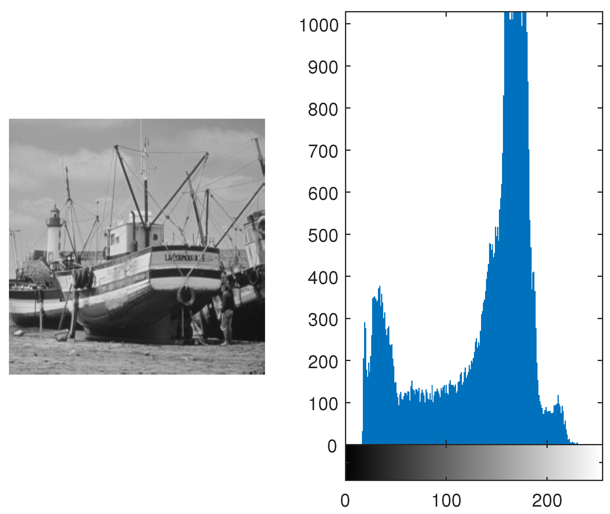
Figure 8.
Original Boat Image and its Histogram depicting various peaks in the pixel intensities
Figure 8.
Original Boat Image and its Histogram depicting various peaks in the pixel intensities
Figure 9.
Encrypted Boat Image with Histogram showing that all pixels are almost uniformally distributed.
Figure 9.
Encrypted Boat Image with Histogram showing that all pixels are almost uniformally distributed.
Table 1.
Input Pixel Intensities for Substitution.
Table 1.
Input Pixel Intensities for Substitution.
| 0 |
1 |
2 |
3 |
4 |
5 |
6 |
7 |
8 |
9 |
10 |
11 |
12 |
13 |
14 |
15 |
| 16 |
17 |
18 |
19 |
20 |
21 |
22 |
23 |
24 |
25 |
26 |
27 |
28 |
29 |
30 |
31 |
| 32 |
33 |
34 |
35 |
36 |
37 |
38 |
39 |
40 |
41 |
42 |
43 |
44 |
45 |
46 |
47 |
| 48 |
49 |
50 |
51 |
52 |
53 |
54 |
55 |
56 |
57 |
58 |
59 |
60 |
61 |
62 |
63 |
| 64 |
65 |
66 |
67 |
68 |
69 |
70 |
71 |
72 |
73 |
74 |
75 |
76 |
77 |
78 |
79 |
| 80 |
81 |
82 |
83 |
84 |
85 |
86 |
87 |
88 |
89 |
90 |
91 |
92 |
93 |
94 |
95 |
| 96 |
97 |
98 |
99 |
100 |
101 |
102 |
103 |
104 |
105 |
106 |
107 |
108 |
109 |
110 |
111 |
| 112 |
113 |
114 |
115 |
116 |
117 |
118 |
119 |
120 |
121 |
122 |
123 |
124 |
125 |
126 |
127 |
| 128 |
129 |
130 |
131 |
132 |
133 |
134 |
135 |
136 |
137 |
138 |
139 |
140 |
141 |
142 |
143 |
| 144 |
145 |
146 |
147 |
148 |
149 |
150 |
151 |
152 |
153 |
154 |
155 |
156 |
157 |
158 |
159 |
| 160 |
161 |
162 |
163 |
164 |
165 |
166 |
167 |
168 |
169 |
170 |
171 |
172 |
173 |
174 |
175 |
| 176 |
177 |
178 |
179 |
180 |
181 |
182 |
183 |
184 |
185 |
186 |
187 |
188 |
189 |
190 |
191 |
| 192 |
193 |
194 |
195 |
196 |
197 |
198 |
199 |
200 |
201 |
202 |
203 |
204 |
205 |
206 |
207 |
| 208 |
209 |
210 |
211 |
212 |
213 |
214 |
215 |
216 |
217 |
218 |
219 |
220 |
221 |
222 |
223 |
| 224 |
225 |
226 |
227 |
228 |
229 |
230 |
231 |
232 |
233 |
234 |
235 |
236 |
237 |
238 |
239 |
| 240 |
241 |
242 |
243 |
244 |
245 |
246 |
247 |
248 |
249 |
250 |
251 |
252 |
253 |
254 |
255 |
Table 2.
Pixels arranged in random order based on CLM with population growth at .
Table 2.
Pixels arranged in random order based on CLM with population growth at .
| 0 |
245 |
223 |
190 |
146 |
91 |
25 |
204 |
116 |
17 |
163 |
42 |
166 |
23 |
125 |
216 |
| 40 |
109 |
167 |
214 |
250 |
19 |
33 |
36 |
28 |
9 |
235 |
194 |
142 |
79 |
5 |
176 |
| 80 |
229 |
111 |
238 |
98 |
203 |
41 |
124 |
196 |
1 |
51 |
90 |
118 |
135 |
141 |
136 |
| 120 |
93 |
55 |
6 |
202 |
131 |
49 |
212 |
108 |
249 |
123 |
242 |
94 |
191 |
21 |
96 |
| 160 |
213 |
255 |
30 |
50 |
59 |
57 |
44 |
20 |
241 |
195 |
138 |
70 |
247 |
157 |
56 |
| 200 |
77 |
199 |
54 |
154 |
243 |
65 |
132 |
188 |
233 |
11 |
34 |
46 |
47 |
37 |
16 |
| 240 |
197 |
143 |
78 |
2 |
171 |
73 |
220 |
100 |
225 |
83 |
186 |
22 |
103 |
173 |
232 |
| 24 |
61 |
87 |
102 |
106 |
99 |
81 |
52 |
12 |
217 |
155 |
82 |
254 |
159 |
53 |
192 |
| 64 |
181 |
31 |
126 |
210 |
27 |
89 |
140 |
180 |
209 |
227 |
234 |
230 |
215 |
189 |
152 |
| 104 |
45 |
231 |
150 |
58 |
211 |
97 |
228 |
92 |
201 |
43 |
130 |
206 |
15 |
69 |
112 |
| 144 |
165 |
175 |
174 |
162 |
139 |
105 |
60 |
4 |
193 |
115 |
26 |
182 |
71 |
205 |
72 |
| 184 |
29 |
119 |
198 |
10 |
67 |
113 |
148 |
172 |
185 |
187 |
178 |
158 |
127 |
85 |
32 |
| 224 |
149 |
63 |
222 |
114 |
251 |
121 |
236 |
84 |
177 |
3 |
74 |
134 |
183 |
221 |
248 |
| 8 |
13 |
7 |
246 |
218 |
179 |
129 |
68 |
252 |
169 |
75 |
226 |
110 |
239 |
101 |
208 |
| 48 |
133 |
207 |
14 |
66 |
107 |
137 |
156 |
164 |
161 |
147 |
122 |
86 |
39 |
237 |
168 |
| 88 |
253 |
151 |
38 |
170 |
35 |
145 |
244 |
76 |
153 |
219 |
18 |
62 |
95 |
117 |
128 |
Table 3.
Complexity Analysis of Different Permutation Algorithms with the Proposed Algorithm
Table 3.
Complexity Analysis of Different Permutation Algorithms with the Proposed Algorithm
| Algorithms |
Space Complexity |
Permutation Time |
| |
|
256 × 256 |
512 × 512 |
1024 × 1024 |
| Proposed Algorithm |
|
1.5ms |
6ms |
18ms |
| Ref. [15] |
|
20ms |
80ms |
330ms |
| Ref. [22] |
|
4ms |
16ms |
68ms |
| Ref. [28] |
|
2.5ms |
10ms |
42ms |
Table 4.
NoPCR
| Image Name |
NoPCR |
| Lena (256,256) |
99.2282 |
| Black Image (All zeros) |
99.2282 |
| Cameraman (256,256) |
99.2282 |
| Baboon (512,512) |
99.4743 |
| White Image (All ones) |
99.2282 |
| Peppers (512,512) |
99.4742 |
| Random Image [0 255] |
99.2282 |
| Barbara (512,512) |
99.4743 |
| Lena (512,512) |
99.4804 |
Table 5.
UAPCI
| Image Name |
UAPCI |
| Lena (256,256) |
12.5527 |
| Black Image (All zeros) |
18.5472 |
| Cameraman (256,256) |
12.1591 |
| Baboon (512,512) |
7.2304 |
| White Image (All ones) |
6.5406 |
| Peppers (512,512) |
7.1747 |
| Random Image [0 255] |
12.5526 |
| Barbara (512,512) |
7.2447 |
| Lena (512,512) |
7.1499 |
Table 6.
SAC Comparison of Various Algorithms
Table 6.
SAC Comparison of Various Algorithms
| S - Boxes |
SAC |
| Proposed S-box |
0.491 |
| AES [45] |
0.504 |
| APA [45] |
0.5 |
| Gray [45] |
0.499 |
| S8 AES [45] |
0.504 |
| Skipjack [45] |
0.503 |
| Xyi [45] |
0.502 |
| Prime [45] |
0.516 |
Table 7.
Entropy of Various Images
Table 7.
Entropy of Various Images
| Image Name |
Original Image |
Cipher Image |
| Lena (256,256) |
7.5683 |
7.9956 |
| Lena (512,512) |
7.4318 |
7.9956 |
| Cameraman (256,256) |
7.0097 |
7.9907 |
| Black Image (All zeros) |
0 |
7.6822 |
| Barbara (512,512) |
7.3925 |
7.9960 |
| White Image (All ones) |
0 |
7.6822 |
| Peppers (512,512) |
7.5700 |
7.9958 |
| Random Image [0 255] |
7.9951 |
7.9972 |
| Baboon (512,512) |
7.2288 |
7.9952 |
Table 8.
Entropy of Various Algorithms
Table 8.
Entropy of Various Algorithms
| Algorithm |
Entropy |
| Proposed Algorithm |
7.9952 |
| AES [48] |
7.91 |
| AES+A5/1 [48] |
7.96 |
Table 9.
MAD Analysis of Various Images
Table 9.
MAD Analysis of Various Images
| Image Name |
MAD |
| Lena (256,256) |
77.90740 |
| Lena (512,512) |
72.82140 |
| Cameraman (256,256) |
79.01410 |
| Black Image (All zeros) |
127.9119 |
| Barbara (512,512) |
72.60550 |
| White Image (All ones) |
127.0529 |
| Peppers (512,512) |
78.51690 |
| Random Image [0 255] |
85.23000 |
| Baboon (512,512) |
69.36040 |
Table 10.
Correlation of Various Images
Table 10.
Correlation of Various Images
| Image Name |
Correlation Value |
| Lena (256,256) |
0.0021 |
| Black Image (All zeros) |
NaN |
| Cameraman (256,256) |
-0.0048 |
| Baboon (512,512) |
0.001 |
| White Image (All ones) |
NaN |
| Peppers (512,512) |
-0.0027 |
| Random Image [0 255] |
-0.000542209 |
| Barbara (512,512) |
0.0016 |
| Lena (512,512) |
-0.0071 |
Table 11.
Correlation of Various Algorithms
Table 11.
Correlation of Various Algorithms
| Algorithm |
Correlation Between Various Algorithms |
| Proposed Algorithm |
0.0028 |
| AES [48] |
0.072 |
| AES+A5/1 [48] |
0.067 |
| AES+W7 [48] |
0.025 |
Table 12.
The Contrast of Various Images
Table 12.
The Contrast of Various Images
| Image Name |
Original Image |
Cipher Image |
| Lena (256,256) |
235 |
255 |
| Black Image (All zeros) |
0 |
255 |
| Baboon (512,512) |
203 |
255 |
| White Image (All ones) |
0 |
255 |
| Peppers(512,512) |
228 |
255 |
| Lena (512,512) |
217 |
255 |
| Random Image [0 255] |
255 |
255 |
| Barbara (512,512) |
210 |
255 |
| Cameraman (256,256) |
246 |
255 |
Table 13.
Homogeneity of Various Images
Table 13.
Homogeneity of Various Images
| Image Name |
Original Image |
Cipher Image |
| Lena (256,256) |
0.8573 |
0.3874 |
| Black Image (All zeros) |
0.9961 |
0.3828 |
| Baboon (512,512) |
0.7988 |
0.3872 |
| White Image (All ones) |
0.9961 |
0.4345 |
| Peppers(512,512) |
0.8946 |
0.3886 |
| Random Image [0 255] |
0.9961 |
0.4345 |
| Barbara (512,512) |
0.8560 |
0.3880 |
| Cameraman (256,256) |
0.8918 |
0.3907 |
| Lena (512,512) |
0.8813 |
0.3899 |
|
Disclaimer/Publisher’s Note: The statements, opinions and data contained in all publications are solely those of the individual author(s) and contributor(s) and not of MDPI and/or the editor(s). MDPI and/or the editor(s) disclaim responsibility for any injury to people or property resulting from any ideas, methods, instructions or products referred to in the content. |
© 2024 by the authors. Licensee MDPI, Basel, Switzerland. This article is an open access article distributed under the terms and conditions of the Creative Commons Attribution (CC BY) license (http://creativecommons.org/licenses/by/4.0/).
