Preprint
Review

Review of the Integration of Hybrid Electric Turbocharger for the Mass-Produced Road Vehicles

Altmetrics

Downloads

237

Views

40

Comments

0

A peer-reviewed article of this preprint also exists.

Submitted:

06 February 2024

Posted:

07 February 2024

You are already at the latest version

Alerts
Abstract
This study conducts a comprehensive review of the integration of Hybrid Electric Turbochargers in mass-produced road vehicles. The primary objective is to inform the readers about the potential advantages and innovative applications of HETs. Employing a SWOT analysis, the research compares the performance of HETs on thermal engines versus traditional turbochargers and HETs on thermal engines versus HETs on hybrid engines based on a synthesis of multiple research findings. The study elucidates the fundamental mechanics of turbochargers, emphasizing their inherent benefits. Additionally, it introduces a novel approach with the integration of the hy-brid-electric turbocharger, demonstrating its capacity, supported by practical examples. The in-corporation of turbochargers with energy recovery mechanisms, including HETs, is shown to significantly contribute to emissions reduction. Moreover, the electric drive facilitates the utili-zation of hybrid turbines, particularly on low-displacement engines, resulting in enhanced effi-ciency, torque, and liter power. In conclusion, the research underscores the potential of HETs to substantially mitigate the environmental impact of the transportation sector by reducing emis-sions and conserving energy. Their ability to optimize the fuel efficiency and power output of internal combustion engines, coupled with the feasibility of downsized engines, positions HETs as an attractive option for both manufacturers and consumers. However, it is acknowledged that the implementation of HETs is in its early stages, necessitating further research to comprehensively understand their environmental impact. Despite this, the promising positive impact on the en-vironment designates HETs as a technology deserving close attention in the forthcoming years.
Keywords: 
Subject: Engineering  -   Automotive Engineering

1. Introduction

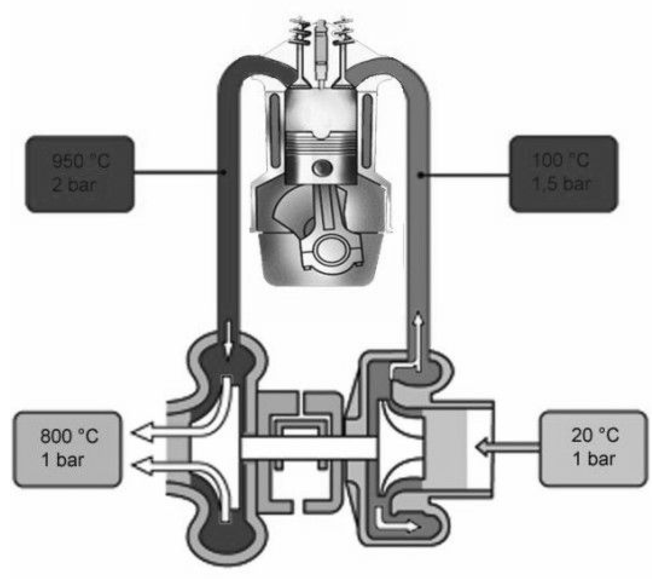
The turbocharger was patented in 1905 by Swiss Alfred Büchi [1]. Its first applications in engines are connected to the aviation field through the contribution of French Auguste Rateau, who created a turbocharged aircraft engine during the First World War. The turbocharger is an aggregate consisting of a joint on a common shaft of the turbine; thus it works as a pneumatic machine, fed by exhaust gases from the engine, which produces a mechanical work. The compressor acts as a pneumatic machine driven by turbine energy, which draws atmospheric air to which the pressure increases. Figure 1 shows a schematic of how the turbocharger works with the engine [1]. This paper suggests technical solutions to turn the classical turbocharger into a hybrid electric turbocharged vehicle. This technical solution has not yet been adopted in the mass production of road vehicles, and it could lead to a significant improvement on internal combustion cogenerated electrical propulsion vehicles, through aiming to have an operational influence on the energetic efficiency for both power delivery and pollutant emission values [2,3]. It is well established that in urban areas the major air pollution factor is the operation of vehicles [2]. The solution can be used upon further increasing the energetic efficiency of a gas cogenerated electrical generator.

1.1. The Connection between a Turbocharger and a Spark-Ignition Engine

The transformation of thermal energy into mechanical energy in an internal combustion engine is a very complex process, and its development, under real conditions, is accompanied by large energy losses. In internal combustion engines, in order to achieve the actual cycle, it is necessary to evacuate the gases from the cylinder and to introduce a fresh charge of air or a mixture of air and fuel. During the evacuation of the burned gas, due to the gas-dynamic resistance, the burnt gas pressure continuously varies and remains slightly higher than the atmospheric pressure [1,5].
During the intake period, the piston moves from top dead center (TDC) to bottom dead center (BDC), the intake valve is open, and the waste gas pressure begins to decrease to atmospheric value. Subsequently, at the cylinder inlet, the fresh mixture, due to the gas-dynamic resistances in the air supply system (air filter resistance, length and section of pipes, the existence of elbows in the air supply system, the roughness of the pipe walls, the suction resistance of fresh mixture from carburetor at MAS, etc.), the pressure drops below atmospheric.
The decrease in pressure during the intake is accentuated by the increase in engine speed, primarily due to an upsurge in the gas-dynamic resistance and to the increasing speed of the fresh mixing current.
The power of a spark-ignition engine is reliant on the amount of fuel burned in the engine per cycle, and the calorific value of the fuel. At constant dosing and engine speed, doubling the power developed by the engine is possible by doubling the amount of fuel burned in the engine per cycle. In order to maintain the dosage, combustion maintenance requires doubling the amount of air introduced into the engine at higher atmospheric pressure, so that in the same cylinder capacity, at the same speed and at the same dosage, the double amount of fuel can be burned. Thus, the power of the engine is proportional to the air consumption. Increasing air consumption in a four-stroke engine is achieved at the same speed and displacement, most realistically by increasing the density of air. This is currently achieved with a compressor, which compresses the air from the initial inlet pressure p0 to the pressure ps, where ps represents the newly requested pressure at certain engine speeds. The air is compressed at pressures of 0.12, 0.32 MPa [6,7].
The amount of fresh charge retained in the cylinder also depends on the degree of evacuation of the cylinder of the burnt gases from the previous cycle. As a result, the intake process must be analyzed in close connection with the parameters that are specific to the exhaust process. The set of phenomena that accompany the evacuation and intake processes represents the exchange of gases, which must be carried out in such a way that as much fresh gas as possible is introduced into the cylinder, in relation to the available volume. A small amount of fresh gas is lost when emptying the burnt gas.
The turbocharger is built with a turbo compressor group, consisting of a centrifugal compressor and a turbine that processes part of the energy of the exhaust gases. The compressor and the turbine are fixed on a common shaft. Although there is no mechanical connection between the compressor and the motor, the unit is self-adjustable. Thus, as the engine speed and load change, the flow rate also changes the burned gas temperature, hence the operating mode of the turbo-compressor. There are two options for achieving a high degree of overfeeding, namely:
1. Increasing the pressure drop in the turbine, therefore increasing the pressure in front of it by opening the exhaust valve earlier, or by a higher advance to the exhaust if necessary.
2. Increasing the gas temperature in the turbine inlet (Tt), which is limited due to the temperature of the vane material to 780, 850 K. When this limit is exceeded, the exhaust gases are diluted with fresh air [8].
The supercharging achieved by using the exhaust gas energy is performed by turning the kinetic energy of the exhaust gases into mechanical compression work. The transformation of the kinetic energy of the flue gases into mechanical compression work is achieved by means of the turbocharger unit. Turbocharging does not involve the consumption of additional energy as the exhaust gas energy is sufficient to drive the turbine and the compressor.
That is why this method of turbocharging has become one of the most widely used methods. Most four-stroke turbocharged engines use the turbocharger since it improves the engine efficiency. The turbocharger is automatically adapted to the flow and temperature of the exhaust gas. Compared to a naturally aspirated engine, turbocharged engines provide lower emissions in specific applications [9].
For many turbocharged engine manufacturers, power supply has not been a gain but only a source of accelerating wear by increasing the mechanical and thermal load. This aspect has been brilliantly overcome, currently registering a level of maintainability comparable to that of the main components and aggregates of the engine. This guarantees an operation without major deficiencies of 1 million km, without the need to replace the unit.
For supercharged petrol engines, required remedial measures include:
-
reducing the compression ratio;
-
improving the roadholding by considering the quality of additional accessories (brakes, chassis, suspension) in order to tune the car to the new performances of the engine;
-
calibration of the turbocharger (TS unit) with the engine (perfect cooperation of the TS with the other systems and engine units), which requires a significant number of tests be conducted on stands and on the road;
-
correction of ignition advance curves;
-
use of reinforced pistons;
-
use of a more mechanically and thermally resistant cylinder head gasket;
-
crankshaft consolidation;
-
modification of the intake route;
-
modification of the cooling system, in order to obtain a more intense cooling of the upper part of the cylinders and of the cylinder head near the exhaust valve;
-
modification of the gas exhaust circuit;
-
increasing the capacity of the air filter;
-
the lubrication system is improved through the oil flow increase. If necessary, a radiator is inserted in the oil circuit. Forcibly stressed engines require forced cooling of the pistons.
-
in the case of a supercharged petrol engine, particular attention must be paid to the study of thermal stresses due to the fact that the motor has a tendency to burn with detonation when stresses upsurge.
Turbocharging also brings advantages, including:
-
increase of the power per liter (by increasing the dose of the fuel mixture per cycle);
-
reduction of noise and chemical pollution;
-
reduction of smoke;
-
slight reduction in fuel consumption;
-
increased silence when evacuating gases;
-
improving the operation in terms of altitude;
-
reduction of gas dynamic losses;
-
increasing the elasticity and adaptability of the engine.

1.2. The Way Turbochargers Work

The most popular supercharging solution is based on a gas turbine, and the process is commonly referred to as turbocharging. The gas turbine (centrifugal compressor) is mostly common in small- dimension car engines. Despite its small size, the turbine is efficient due to the high speeds at which it works, ranging between 40,000, ..., 100,000 rot/min.
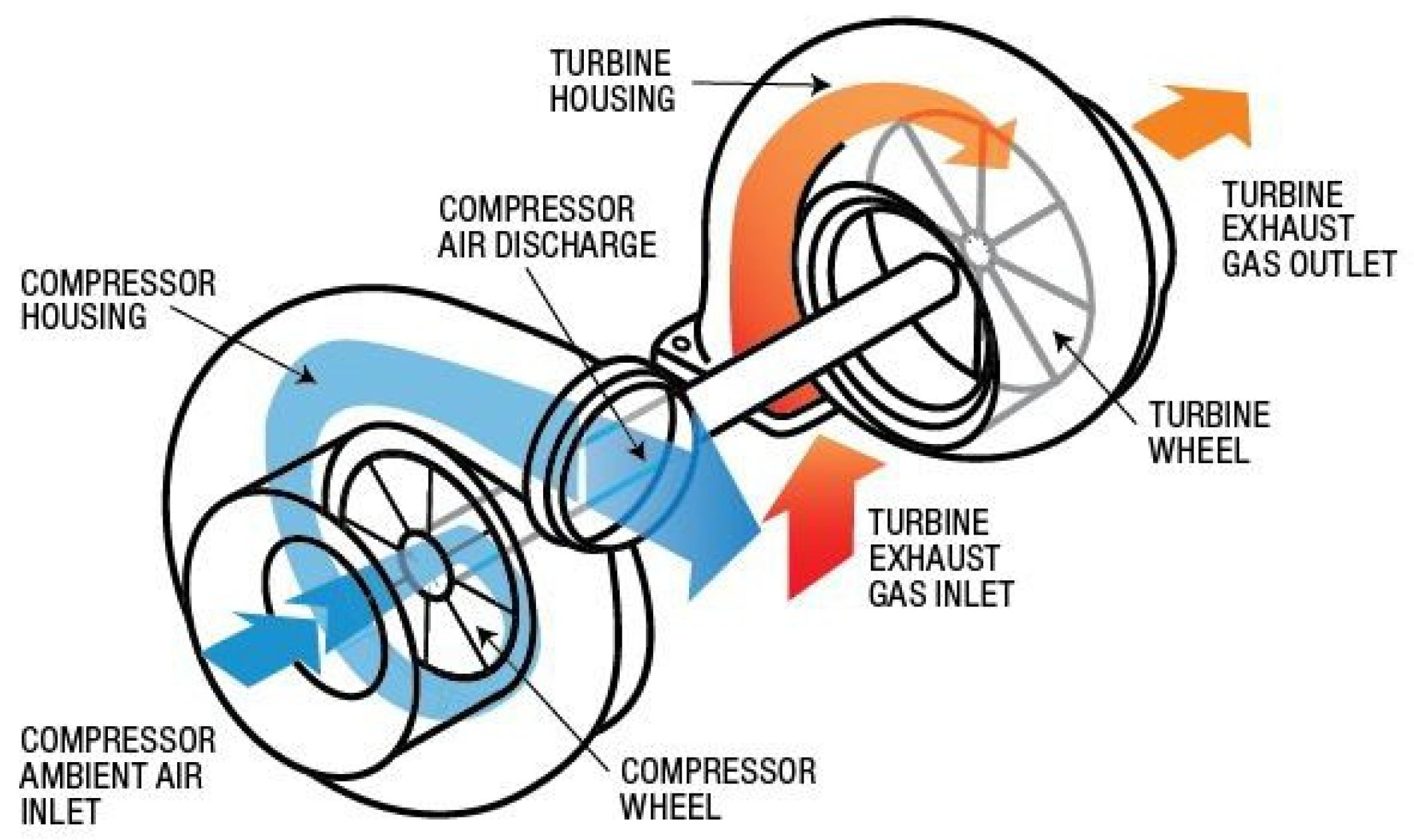
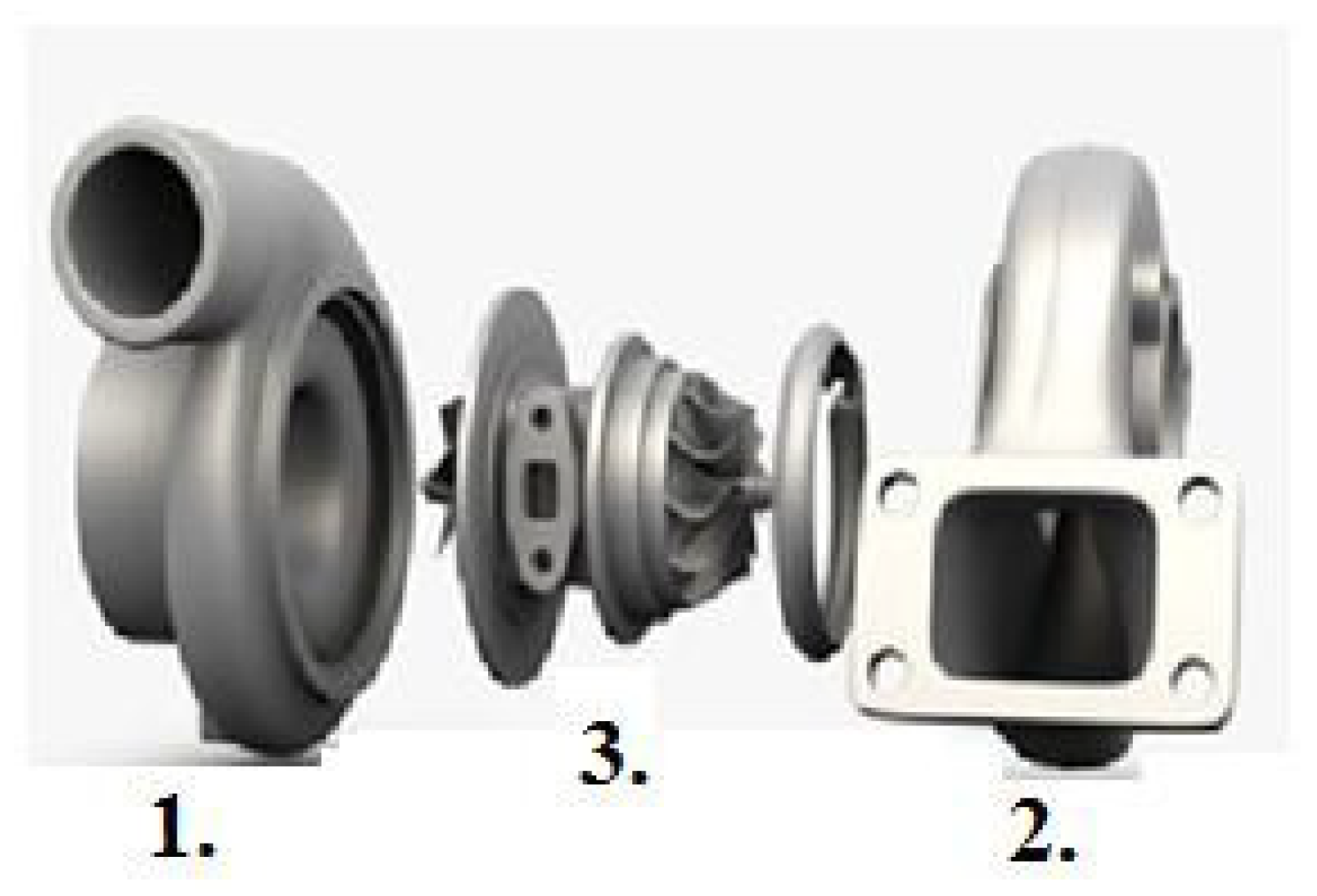
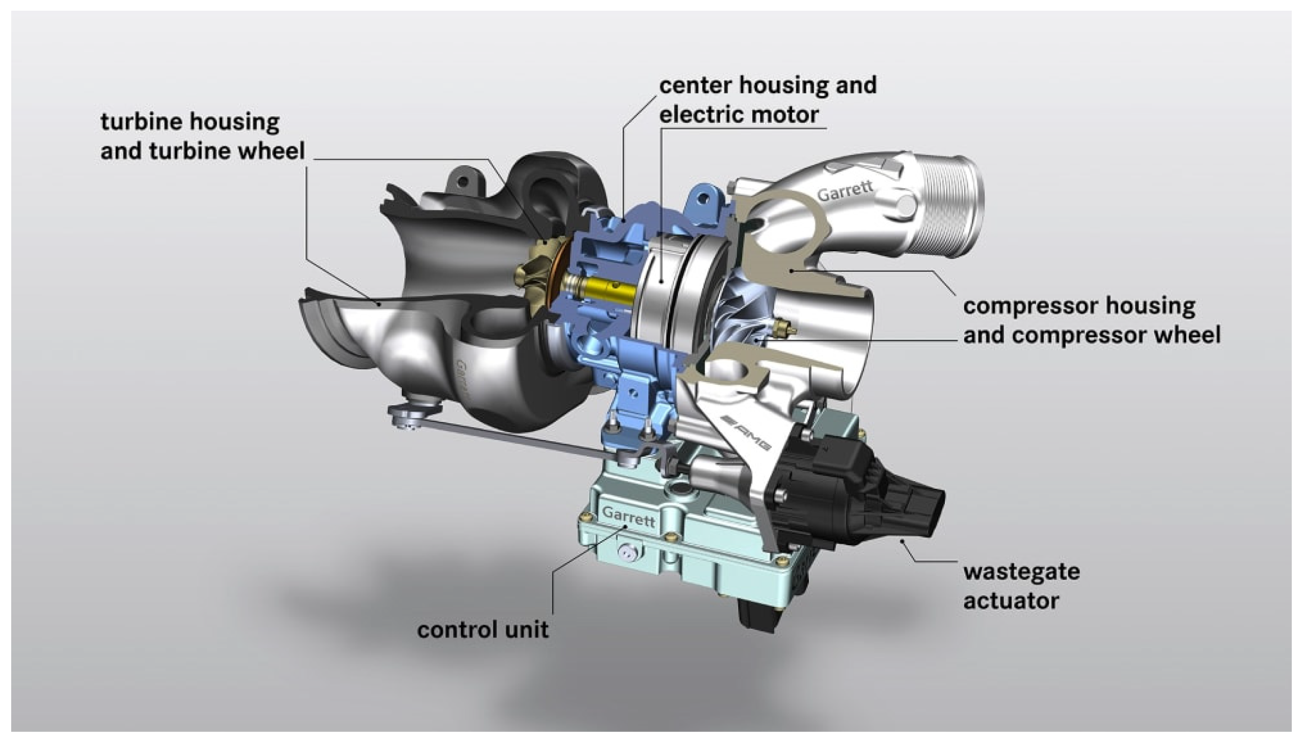
Figure 3 and Figure 4 illustrate an exploded view of a turbocharger and the gas flow both through the compressor and the turbine. The compressor assembly consists of a rotary compressor with pallets, housing, air inlet duct, air outlet duct. The compressors used are equipped with an axial air inlet and a radial outlet; the peripheral speed of the pallets can reach 520 m/s.
The composition of the turbine assembly comprises basic elements. The rotor, on which the vanes are arranged, the housing having the typical shape, the radial entrance, the axial output. The vane rotor consists of nickel and chrome alloys, as they must withstand temperatures that can reach 1,050° C.
The compressor and the turbine are fixed on the central part. It contains the bearings of the central axis of the turbine and the lubrication channels. As the turbine shaft reaches very high speeds during operation, it constantly needs lubrication, and the oil also has the role of cooling. As for high heat-required turbines, a liquid cooling circuit may also be needed in addition to the lubrication circuit. The central crankcase includes part of the turbine crankcase and part of the blower crankcase, which form the rigid stator assembly. This assembly must ensure mechanical rigidity capable of blocking the heat flow from the turbine to the blower as well as ensuring the bearings of the common shaft from excessive heating. The wheel assembly can reach speeds of l00,000 ... 150,000 rot/min; therefore, reducing the length of the wheel shaft recommends placing the supports between the blower wheel and the turbine wheel, with the disadvantage that the bearings cannot be reached and must be protected against overheating (mounting “Inboard”, applied to centripetal turbines, where the entry of gases into the turbine is simple, and the installation of the assembly on the exhaust manifold becomes rational) [5].
The risk of vibration is posed by the overwhelming disproportion between the low mass of the blower wheels (made of aluminum alloys) and the high mass of the turbine wheels (made of refractory steels). Furthermore, the very high speeds require very low bearing loads.
The heat radiated by the turbine tends to diffuse toward the inside of the crankcase, crossing the turbine bearing; therefore, a thermal protective ‘bell’ is inserted between the turbine wheel and the bearing crankcase.
If turbochargers had been designed to produce maximum power at maximum engine speed, they would have increased dimensions and an appreciable weight of rotating moving parts, which would affect the response time in the case of low operating speeds. Reducing the size of the unit is desirable, but this is done so that it produces an acceptable level of power at low speeds and responds promptly to acceleration.
The use of a small turbocharger involves a high operating speed and increases the risk of overpressure. In this situation, the operating speed of the turbine must be reduced, which can be achieved by means of a valve that limits the gas flow.
This valve, commonly known as a “wastegate” in English, is operated by means of a rod that connects to a vacuum capsule, its operation being highlighted in the following figure.
Note: Particular attention must be paid to the adjustment of the control rod with which the vacuum capsule is equipped.
For a turbine, there are two areas of malfunction:
In the case of low speed - the turbine speed is very low. In this case, the air will not be compressed sufficiently by the blower and the engine will not reach the desired parameters (turbo hole or “turbo lag”).
In the case of high speed - the turbine speed is very high. In this case, the air will be compressed more than necessary; therefore, part of the exhaust gas flow will be exhausted through the “by-pass” valve of the turbine (bypass valve), so that the optimum value of compression is not exceeded.
When the turbocharger with by-pass was introduced, an effective compromise solution was chosen (considering that this system exerts no influence over low speeds).
Turbochargers offer significant benefits in terms of boosting engine performance and fuel efficiency, but they are not without their shortcomings. One of the most notable drawbacks is “turbo lag,” a delay in power delivery when accelerating, as the turbocharger takes a moment to spool up and provide boost. Additionally, turbochargers generate heat due to the high-speed rotation of the turbine, which can pose challenges in managing engine temperature. The complexity of turbocharger systems, with components like intercoolers and wastegates, can lead to increased maintenance and repair costs. Durability can be a concern as the extreme conditions within a turbocharger may result in wear and tear over time. Furthermore, the increased exhaust backpressure created by turbochargers may impact engine efficiency and emissions. Turbochargers also rely on a supply of oil for lubrication and cooling, which, if insufficient or inadequately maintained, can lead to damage. The installation and maintenance of turbochargers can be costly, and they may still contribute to emissions, albeit to a lesser extent compared to non-turbocharged engines. Despite these challenges, ongoing advancements in turbocharger technology aim to address these shortcomings and continue to make turbochargers a popular choice for enhancing engine performance and efficiency [1,3,6,8].

1.3. Hybrid-Electric Turbocharger

Nowadays, a great deal of effort is being put into reducing the polluting emissions of internal combustion engines and, at the same time, into increasing their power and torque. Fulfilling this requirement entails the use of a turbocharger, as the power, the torque, but also the fuel economy being higher.
HET (hybrid electric turbocharger) offer a range of innovations that effectively address the shortcomings associated with traditional turbochargers. One of the most significant advantages is the substantial reduction in turbo lag, thanks to the incorporation of an electric motor. This motor provides instant power upon acceleration, greatly enhancing engine responsiveness, particularly at low RPMs. HETs also excel in managing the heat generated by the turbocharger, utilizing the electric motor’s regenerative capabilities to convert excess heat into electrical energy for more efficient use. Furthermore, HETs simplify the turbocharger system by eliminating the need for a wastegate, as the electric motor can precisely control the turbocharger’s speed. This innovation enhances the turbocharger’s durability, as it reduces wear and tear and optimizes the flow of exhaust gases, resulting in lower exhaust backpressure, increased engine efficiency, and reduced emissions. Moreover, HETs are designed to rely less on oil for lubrication and cooling, further contributing to their enhanced efficiency. By recovering energy during deceleration and utilizing it to power various vehicle systems, HETs improve overall engine efficiency, reduce emissions, and mark a significant advancement in turbocharger technology [10,11,12,13].
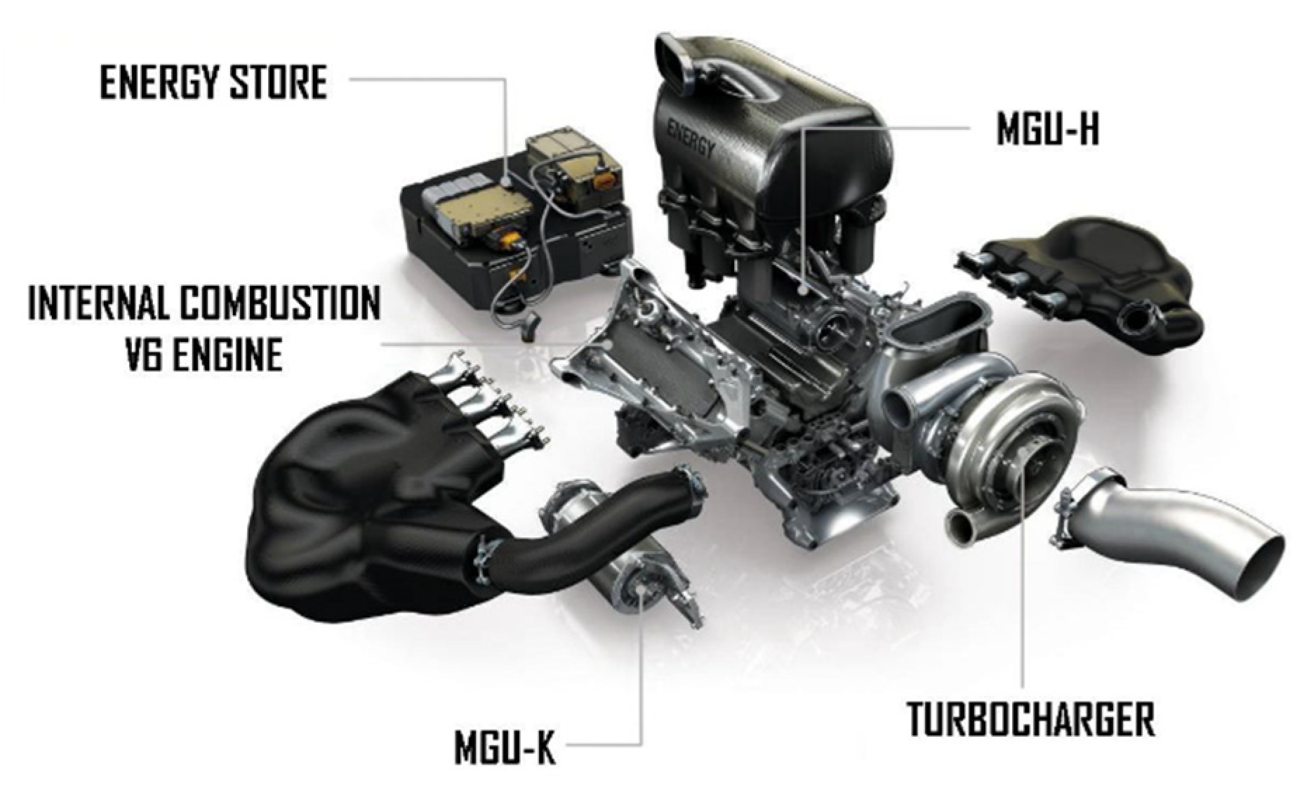
In Formula 1, rules have changed, and the use of supercharged engines has been restored, detrimental to the normally aspirated ones. The cylinder capacity of the current supercharged engine is 1.6 liters in the V6 configuration, unlike the old engine, which had 2.4 liters in the V8 configuration. The major engine manufacturers are prepared for this change and have developed various construction solutions.
Unlike the notorious supercharging systems, which are designed only to increase the pressure and density of the air introduced into the engine, this supercharging system implemented in Formula 1 has certain peculiarities that make it both innovative and revolutionary. These features include the recovery of exhaust energy and the electric drive of the turbocharger [10].
The operating principle is responsible for the recovery of the kinetic energy of the exhaust gases. During the operation of a turbo engine, exhaust energy is used to drive the supercharger, but much of this energy is lost. The recovery of this energy is achieved via a generator coupled to the turbine shaft that transforms the rotational movement of the shaft driven by the exhaust gases into electricity that will be stored in batteries to be used as needed. This system can be coupled with another system to recover the energy lost during braking [12,13,15].

1.4. Electric Drive of the Turbocharger

Hybrid Electric Turbochargers (HETs) are a relatively new and innovative technology in the field of engine turbocharging [16]. They have garnered significant attention in recent years due to their ability to improve the fuel efficiency and power output of internal combustion engines. In addition, they can also play a key role in reducing the environmental impact of the transportation sector. In this article, we will delve into the environmental impact of HETs, specifically focusing on their ability to reduce emissions and conserve energy.
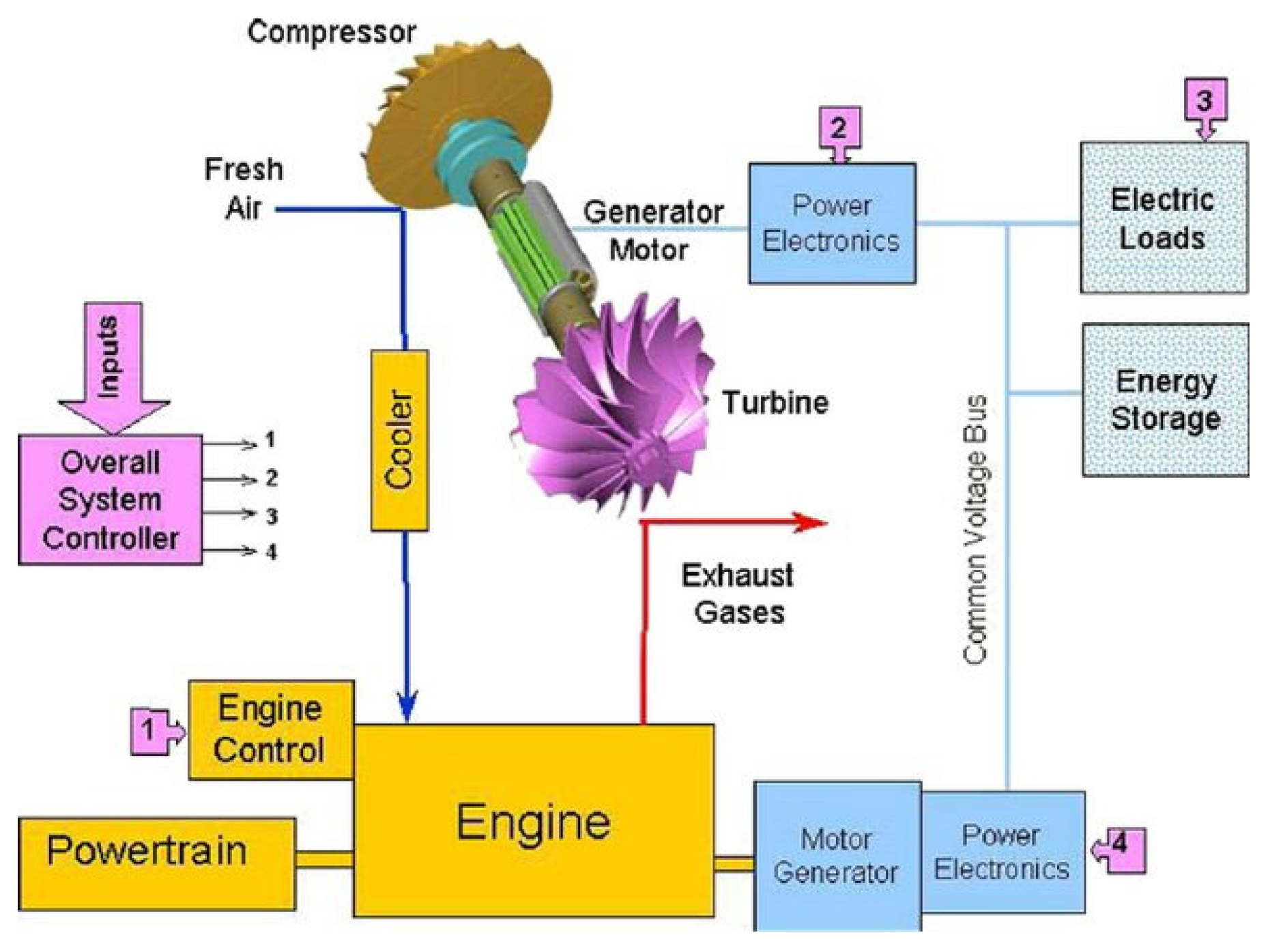
The design, presented in Figure 5, of HETs involves the integration of an electric motor with a traditional turbocharger. This integration allows for improved responsiveness and control over the turbocharger. The electric motor, which is much smaller than that of a full-fledged electric vehicle, is positioned between the turbocharger’s turbine and compressor [16]. It is powered by a battery that can be charged through regenerative braking or other means [16].
They are designed to provide improved engine performance, efficiency, and reduced emissions by combining the advantages of both electric and mechanical turbocharging [17]. HETs consist of a traditional turbocharger and an electric motor-generator that is integrated into the turbocharger’s shaft [18]. The electric motor provides additional boost at low engine speeds, while the traditional turbocharger takes over at higher engine speeds [19]. The electric motor in HETs is typically coupled to the engine’s shaft, but the coupling may not always be direct. It depends on the specific design and the intended purpose. In some cases, the electric motor might be connected directly to the engine’s shaft, allowing it to work in tandem with the engine. However, in other designs, the electric motor might be connected to a generator that produces electricity to power the electric motor. The motor can be engaged or disengaged as needed, depending on the power requirements and efficiency goals. The specifications of the electric motor in HETs, including speed, power, torque, and energy consumption, can vary widely depending on the specific application and design. These specifications are determined based on the intended use and the performance requirements of the system.
HETs are a promising technology that combine the benefits of turbocharging and electrification. HETs use an electric motor to spin the turbocharger’s compressor wheel, providing instant boost to the engine, resulting in improved engine performance and fuel efficiency. In addition to these benefits, HETs offer improved engine response and reduced emissions, making them a compelling solution for the automotive industry [16].
This solution entails the connection of the generator to the turbine shaft. It fulfils the function of a motor and uses the energy stored in batteries to rotate the turbine shaft. The electric drive of the turbine is used when the engine is not running, during braking, when the accelerator pedal is not depressed. Generally, the speed of the turbocharger would decrease if it was not electrically driven. This function is particularly important because, by keeping the turbine at a high speed, even when the exhaust gas speed is low (throttle closed), the phenomenon of “turbo-lag” is prevented (delaying the turbine’s response to acceleration pressure / throttle opening). Since the turbine is being maintained at operating speed by the electric motor, the boost pressure is therefore preserved, eliminating the “turbo- lag”, so when the acceleration is pressed again, the turbine no longer needs the time necessary to increase the speed and therefore increases the pressure [11,15,20].
From the design point of view, the electric motor in HETs serves a crucial role in controlling the speed of the turbocharger. It can be used to spin the turbocharger at low engine speeds, improving engine response and reducing turbo lag [16]. Additionally, the electric motor can be used to spool up the turbocharger more quickly, providing boost at low engine speeds, where traditional turbochargers may struggle to provide enough boost [17]. This results in improved engine performance, reduced fuel consumption, and lower emissions [18]. It must be integrated seamlessly with the engine to ensure proper functioning. The battery used to power the electric motor must also be properly sized and positioned to ensure reliable performance [19]. Furthermore, the electronic control unit (ECU) used to manage the HET system must be designed to ensure that it can properly control the turbocharger, battery, and engine [21].
In the following, several effective solutions that have been adopted by major engine manufacturers are presented.
The technical solution implemented by one of the Formula 1 teams [22,23 consists of a turbo-compressor unit located between the two halves described by the V6 configuration of the engine, the exhaust galleries on one side and the other join in the turbine. The motor generator is located between the turbine and the compressor [10,24].
Using this exhaust gas recovery system, in conjunction with a braking energy recovery system, brings additional power to the wheels of up to 120 kW [25].
Other manufacturers have adopted similar solutions [17]. They are presented in Figure 6 and Figure 7.
The electric drive of the turbine is particularly useful in the production of vehicles in the case of overtaking. For example, on a one-way street, a vehicle traveling at a higher speed catches up with a slower vehicle, such as a truck, and is forced to brake if it does not have conditions to overtake.
When the vehicle brakes, the turbine speed decreases, so that when the acceleration is resumed in order to overtake, there is sufficient waiting time until the turbine turns again.
The electric drive of the turbine eliminates the waiting time and inserts fresh air into the engine at the appropriate boost pressure as if the turbine were driven by exhaust gases. This is particularly helpful in order to overtake faster, the engine torque being available when you press the accelerator without having to wait. Switching from drive motor mode to generator mode is done automatically and is controlled by the engine computer.
A sensor on the throttle or on the pedal determines whether or not the engine is running, and thus the motor generator is operated accordingly.
Another key environmental benefit of HETs is their ability to conserve energy. The electric turbocharger, integrated into the HET system, is powered by a motor, which can be powered by an external energy source such as a battery or a fuel cell. This allows for energy to be stored and used to provide instant boost when needed, reducing the amount of energy required from the engine and improving its overall efficiency.
For example, a study by Dong et al. [13] found that a HET system increased the fuel efficiency of a diesel engine by up to 7% compared to a conventional turbocharger. This improvement in fuel efficiency translates into a reduction in energy consumption and a corresponding reduction in greenhouse gas emissions.
In addition, HETs also offer the potential to conserve energy through the use of regenerative braking. This is because the motor, integrated into the HET system, can act as a generator during deceleration, converting the kinetic energy of the vehicle into electrical energy, which can be stored in a battery or a fuel cell. This stored energy can then be used to provide instant boost when needed, reducing the amount of energy required from the engine and improving its overall efficiency.
In terms of environmental impact, HETs have the potential to reduce emissions and improve fuel efficiency compared to traditional turbochargers. By providing instant boost, HETs can reduce the engine’s reliance on the throttle, leading to reduced pumping losses and improved fuel efficiency. Additionally, HETs can reduce engine out emissions by providing improved air/fuel mixing and more efficient combustion. Furthermore, HETs can be designed to harvest energy from the engine’s exhaust stream, which would otherwise be wasted, to generate electricity for the vehicle’s systems [18]. HETs can lead to improved fuel efficiency by providing additional power to the engine when needed, reducing the need for larger, less fuel-efficient engines. The fuel consumption benefits can vary based on the vehicle type, driving conditions, and the degree of hybridization [18].
It should be noted that the environmental impact of HETs is highly dependent on the system’s design and how it is integrated into the vehicle. For example, the energy source used to spin the turbocharger can significantly impact the overall environmental impact of the system. Using regenerative braking to power the turbocharger can result in a net reduction in emissions, while using the battery to power the turbocharger can result in a net increase in emissions [19].
Overall, HETs offer a number of potential benefits for the automotive industry, including improved engine performance and fuel efficiency, reduced emissions, and improved engine response. However, the full potential of HETs can only be realized through careful system design and integration into the vehicle.
In addition, HETs also offer the potential to reduce emissions by enabling the use of downsized engines. This is because the electric turbocharger can compensate for the reduced air flow caused by downsized engines, ensuring that the engine operates at optimal conditions. A few studies [22,26] found that a HET system improved the fuel efficiency and reduced emissions of a downsized engine by up to 15%.
Improving the performance and efficiency of HETs is crucial for the widespread adoption of this technology in the automotive industry. Here are some ways to improve HETs:
Improved Battery Technology: The battery used to power the electric motor in HETs has a significant impact on the performance and efficiency of the system. Improving the technology used in the battery, such as using more advanced materials, can result in improved energy density and a more compact battery design [27]. This can result in better performance, increased efficiency, and a reduction in overall weight.
Increased Electric Motor Efficiency: The efficiency of the electric motor in HETs can also be improved. This can be achieved by using more advanced materials and manufacturing processes, as well as optimizing the motor’s design [28]. Improving the efficiency of the electric motor can result in improved performance and increased fuel efficiency.
Advanced Control Strategies: The ECU used to manage the HET system can also be improved. Advanced control strategies, such as real-time monitoring of engine performance, can be used to optimize the operation of the HET system [29]. This can result in improved performance and increased fuel efficiency.
Integration with Engine Management Systems: HETs can be integrated with the engine management system to provide improved performance and efficiency [30]. This integration can result in a more seamless and efficient operation of the engine, as well as improved performance and fuel efficiency.
Improved Turbocharger Design: The traditional turbocharger in HETs can also be improved. This can be achieved by using more advanced materials, as well as optimizing the design of the turbocharger [31]. Improving the turbocharger can result in improved performance, increased efficiency, and reduced emissions.
In the realm of HETs, several notable challenges warrant attention during the design process. Firstly, the incorporation of electric components and associated power electronics can introduce heightened complexity and elevated manufacturing and maintenance costs. Moreover, the augmented weight and size stemming from electric motor integration may affect the overall balance and weight distribution of the system, calling for a meticulous design approach [32]. Challenges also arise in the integration of HETs into pre-existing engine configurations, necessitating careful engineering to ensure seamless compatibility and performance optimization. Additionally, the reliance on electrical components within HETs necessitates a heightened focus on system reliability to mitigate potential electrical faults [33,34].
When contemplating the utility of HETs in marine diesel engines, several potential advantages come to the fore. [12] HETs can contribute to heightened fuel efficiency by providing supplementary power during acceleration and high thrust demand scenarios, thereby reducing fuel consumption and operational expenses. Their aptitude for emissions reduction aligns with stringent environmental regulations in the maritime sector, particularly in the context of the International Maritime Organization’s emissions standards. The maritime industry is witnessing a notable trend toward hybrid and electric propulsion systems, which extends the applicability of HETs in this domain. Furthermore, their efficacy is particularly pronounced for vessels with diverse operational profiles that require a dynamic response to varying power demands. In sum, HETs possess significant potential for enhancing the efficiency and environmental sustainability of marine diesel engines [35,36,37].
Designing HETs is a multifaceted endeavor fraught with intricate challenges, with particular attention dedicated to rotor dynamics within the shaft train layout. Key considerations encompass achieving precise balance among rotating components to mitigate vibrations and reduce bearing wear, selecting the appropriate bearing type and size to accommodate load capacity and operating speed while maintaining reliability, adhering to maximum bearing operating speeds to prevent premature failure, establishing an effective lubrication system to minimize friction and heat generation, carefully selecting materials for rotor components to withstand high temperatures and mechanical stress, adapting to variable speed operation to ensure system stability and efficiency, addressing electromagnetic interference concerns arising from electrical integration, designing for durability and reliability under diverse operational conditions, and prioritizing safety by mitigating mechanical failure risks [38,39].

2. Correlation between HET and Hybrid Vehicles

At the core of HET integration lies the objective to surmount inherent challenges in traditional turbocharging, most notably turbo lag. Turbo lag, the delay between driver acceleration input and the delivery of increased power, is a characteristic hurdle in internal combustion engines equipped with conventional turbochargers [41,42,43]. HETs strategically merge traditional turbocharging methods with electric motor augmentation to mitigate turbo lag effectively. The electric motor in HETs facilitates rapid spooling of the turbocharger, resulting in instantaneous boost, particularly evident at lower engine speeds [41,42,43,44,45].
The advantages stemming from the infusion of HET technology into hybrid vehicles are multifaceted. Foremost among these is the marked improvement in engine responsiveness. By eliminating turbo lag [46], HETs contribute to seamless acceleration, providing drivers with a more dynamic and satisfying driving experience. This enhancement in responsiveness is not only a testament to technological innovation but also addresses a longstanding concern in traditional turbocharged engines.
Another salient advantage lies in the realm of fuel efficiency [44,45,46]. The optimized combustion process facilitated by HETs contributes to elevated fuel efficiency, a critical parameter in the context of evolving environmental norms and consumer expectations. The ability to extract more energy from each unit of fuel not only aligns with sustainability goals but also positions HET-equipped hybrid vehicles as contenders in the pursuit of eco-friendly transportation solutions [47,48,49].

2.1. Fuel Efficiency and Emissions

2.1.1. Impact of HETs on Fuel Efficiency

The integration of HETs in hybrid vehicles significantly influences fuel efficiency. HETs play a crucial role in optimizing the combustion process, addressing inefficiencies associated with traditional turbocharged engines. The electric motor in HETs facilitates rapid spooling of the turbocharger, ensuring a continuous and optimal supply of compressed air to the engine [50].
Research studies [45,46,47,48,49,50,51,52,53,54,55] have demonstrated that HET-equipped hybrid vehicles exhibit notable improvements in fuel efficiency, particularly in urban driving conditions where frequent acceleration and deceleration occur. The reduction in turbo lag contributes to smoother acceleration, allowing the engine to operate more efficiently across a wider range of speeds.

2.1.2. Emissions Reduction

The optimized combustion process facilitated by HETs not only enhances fuel efficiency but also contributes to a reduction in emissions. By ensuring a more complete combustion of fuel, HETs help minimize the release of pollutants into the atmosphere.
Studies [55,56,57,58,59,60] comparing emission levels between traditional turbocharged engines and those with HET integration have shown a decrease in nitrogen oxide (NOx) and particulate matter emissions. The ability of HETs to deliver instant boost, even at lower engine speeds, ensures that the combustion process is more controlled and efficient, resulting in cleaner exhaust emissions.

2.2. Integration Challenges and Solutions

2.2.1. Technical Challenges

The integration of HETs with hybrid systems introduces technical challenges that require careful consideration. One notable challenge is the coordination of the electric motor and turbocharging components to ensure seamless operation [61]. The complexity of managing these diverse elements within the powertrain system necessitates advanced control algorithms and sophisticated electronic systems [62,63].
Ongoing research [64,65,66,67,68] focuses on developing intelligent control strategies that optimize the collaboration between the electric motor and the turbocharger. These strategies aim to address issues related to transient response, torque delivery, and energy management, ensuring a harmonious integration that maximizes the benefits of both systems.

2.2.2. Increased Complexity

The inclusion of HETs adds a layer of complexity to the overall powertrain system of hybrid vehicles. This complexity poses challenges not only in terms of engineering but also in terms of maintenance and repair. Automotive technicians require specialized training to diagnose and address issues related to the hybridized turbocharging system [64].
To mitigate this challenge, manufacturers are investing in training programs for service technicians, and diagnostic tools are being developed to streamline the troubleshooting process. Additionally, advancements in predictive maintenance technologies aim to proactively identify potential issues before they escalate, reducing downtime and enhancing the reliability of HET-equipped hybrid vehicles.

2.3. Battery and Energy Management

2.3.1. Synergy with Hybrid Vehicle Battery Systems

The synergy between HETs and hybrid vehicle battery systems is a critical aspect of their integration. The electric motor in HETs interacts with the hybrid’s energy management system, contributing to the overall efficiency and sustainability of the powertrain [61,62,63,64,65].
Studies have explored the potential for regenerative braking systems in HET-equipped hybrids. During deceleration, the electric motor in HETs can act as a generator, converting kinetic energy into electrical energy and storing it in the hybrid vehicle’s battery. This regenerative braking capability enhances overall energy recovery and contributes to the extended range of hybrid vehicles [66,67,68].

2.3.2. Energy Recovery and Efficiency

One of the key advantages of integrating HETs with hybrid systems lies in their ability to contribute to energy recovery. The electric motor assists in capturing and storing excess energy during braking or deceleration, which can then be utilized to power auxiliary systems or provide additional propulsion during acceleration.
Research [69,70,71,72] indicates that this regenerative capability not only enhances energy efficiency but also extends the lifespan of the hybrid vehicle’s battery. The seamless integration of HETs with energy management systems ensures that the recovered energy is judiciously distributed, optimizing overall powertrain efficiency.

2.4. Cost-Benefit Analysis

2.4.1. Production Costs

The integration of HETs into hybrid vehicles introduces additional components and advanced technologies, which can impact production costs. The manufacturing process involves the incorporation of electric motors, control systems, and associated components, adding complexity to the assembly line.
However, economies of scale and advancements in manufacturing techniques are gradually mitigating this challenge. As demand for hybrid vehicles with HETs increases, manufacturers are optimizing production processes, leveraging technological advancements, and exploring cost-effective materials to manage production costs effectively [72,73].

2.4.2. Maintenance Expenses

While the increased complexity of HET-equipped hybrid vehicles poses challenges in terms of maintenance, advancements in diagnostic tools and predictive maintenance technologies aim to streamline service procedures. The specialized training of automotive technicians ensures that maintenance tasks related to the hybridized turbocharging system can be performed efficiently.
Studies [65,66,67,68,69,70,71,72,73,74] suggest that the long-term maintenance expenses of HET-equipped hybrid vehicles can be comparable to or even lower than those of traditional vehicles when considering factors such as fuel savings and extended battery life. The overall cost of ownership, including maintenance, becomes a critical parameter in the cost-benefit analysis for consumers considering HET-equipped hybrid vehicles.

2.5. Fuel Consumption Savings

A significant aspect of the cost-benefit analysis revolves around the savings in fuel consumption achieved through the integration of HETs. Research [70,71,72,73,74,75] has demonstrated that HET-equipped hybrid vehicles exhibit improved fuel efficiency, translating into tangible savings for the vehicle owner over the lifespan of the vehicle.
Government incentives, tax credits, and fuel efficiency regulations further enhance the economic attractiveness of HET-equipped hybrid vehicles. Consumers weighing the initial cost against long-term savings in fuel consumption find a compelling economic case for choosing hybrid vehicles with integrated HET technology.

3. Materials and Methods

3.1. SWOT Analysis

A comprehensive SWOT analysis is integral to discerning the nuanced dynamics that underlie the integration of HETs in mass-produced road vehicles.
Strengths: The incorporation of electric motor augmentation in HETs addresses a longstanding challenge in turbocharged engines—turbo lag. The result is swift and seamless acceleration, translating into superior overall vehicle performance. This strength positions HET-equipped vehicles as contenders for drivers seeking an enhanced driving experience [75,76].
Weaknesses: However, the infusion of HETs introduces a layer of complexity to the powertrain system. This complexity may translate into maintenance challenges, requiring a commensurate investment in specialized knowledge and resources. Furthermore, the incorporation of electric components elevates the overall cost of the vehicle, potentially impacting market competitiveness [77].
Opportunities: The contemporary landscape witnesses a growing market for eco-friendly vehicles, providing a substantial opportunity for the adoption of hybrid models featuring HETs. As advancements in electric motor and battery technologies continue, there exists promising potential for further refinement and optimization of HET integration, aligning with broader trends toward sustainable transportation [77,78].
Threats: Notwithstanding the opportunities, the ascent of fully electric vehicles poses a formidable threat to the market share of hybrid models featuring HETs. The competition from vehicles exclusively relying on electric propulsion, without the complexities associated with hybrid systems, challenges the positioning of HET-equipped vehicles in the market. Additionally, consumer perceptions concerning the intricacy and reliability of hybrid systems pose a potential threat to widespread adoption [79,80].
In this dedicated section, a meticulous comparative SWOT analysis unfolds, meticulously examining two distinctive scenarios involving Hybrid Electric Turbochargers (HETs). The intricacies of the first scenario, elucidated in Table 1, explore the seamless integration of an HET on a traditional thermal engine. This integration strategically targets heightened performance and augmented fuel efficiency, addressing longstanding challenges in conventional turbocharging. In parallel, Table 2 navigates the intricate landscape of an HET incorporated into a hybrid engine, synergizing electric and thermal propulsion systems. This thorough investigation seeks not only to highlight the distinctive strengths, weaknesses, opportunities, and threats intrinsic to each configuration but also to offer a nuanced understanding of their potential implications. Through the comparative lens, the aim is to unravel profound insights into the dynamic landscape of employing HETs across divergent engine architectures.

4. Discussion

In the context of this study on hybrid-electrical turbochargers and the measurement of spool time, a comprehensive discussion of the obtained results and their interpretation is presented. The findings of the investigation, particularly focusing on spool time measurements, are scrutinized within the framework of the working hypotheses that guided the research.
The analysis extends beyond the confines of this study, as the results are situated within the broader landscape of existing literature and the current state of hybrid-electrical turbocharger technology. This contextualization enables meaningful conclusions about the implications of the findings and their relevance in advancing the understanding of turbocharger performance and responsiveness within thermal engines.
Moreover, the profound impact of hybrid-electrical and electric vehicle (EV) technologies in reshaping the automotive industry is acknowledged. The integration of hybrid-electrical systems, such as the one examined in this study, offers a range of benefits, including enhanced fuel efficiency, reduced emissions, and improved power delivery. These advantages align with the broader goals of sustainability and energy efficiency in the automotive sector.
Furthermore, the significance of this work in paving the way for future research endeavors is recognized. Potential avenues for further exploration and improvements within the realm of hybrid-electrical turbocharger systems are highlighted, drawing inspiration from the valuable insights gleaned during the course of this study.

5. Conclusions

In conclusion, Hybrid Electric Turbochargers (HETs) offer a transformative solution to mitigate the environmental impact of the transportation sector. Employing a rigorous SWOT analysis, this study evaluates HETs on thermal-only and hybrid engines, emphasizing their strengths, weaknesses, opportunities, and threats.
The analysis showcases the potential of HETs to reduce emissions and enhance energy efficiency, making them an appealing choice for manufacturers and consumers. The study explores the integration of HETs in both thermal-only and hybrid engines, highlighting their adaptability and benefits such as high torque and increased liter power.
The proposed system allows the charging of the main energy source of the electric engine and subsequent energy utilization, extending the advantages of HETs to both engine types. While the environmental benefits are evident, ongoing research is crucial for a comprehensive understanding of the efficiency implications. HETs remain a technology deserving close attention in the automotive industry, proved by the systematic SWOT analysis presented.

Author Contributions

Conceptualization, C.C.S, S.V.I, I.V. and I.I; methodology, C.C.S, S.V.I, I.V. and I.I; software; validation, C.C.S, S.V.I, I.V. and I.I.; formal analysis, C.C.S, S.V.I, I.V. and I.I.; investigation, C.C.S, S.V.I, I.V. and I.I.; resources, C.C.S, S.V.I, I.V. and I.I.; data curation, C.C.S, S.V.I, I.V. and I.I.; writing—original draft preparation, C.C.S, S.V.I, I.V. and I.I; writing—review and editing, C.C.S, S.V.I, I.V. and I.I.; visualization, C.C.S, S.V.I, I.V. and I.I.; supervision, I.I.; project administration, I.I.; funding acquisition. All authors have read and agreed to the published version of the manuscript.

Funding

This research received no external funding.

Data Availability Statement

All datasets generated or analyzed during this study are included in the article and its supplementary information files. No additional data is available.

Acknowledgments

The authors extend their appreciation for the integral role this research played in the PhD program of the first author at the Politehnica University of Timisoara. The first author expresses gratitude to the esteemed teaching staff of both Politehnica University of Timisoara and University of Aurel Vlaicu (Romania), where he pursued his studies. Their guidance and support significantly contributed to the successful completion of this work and the overall academic journey.

Conflicts of Interest

The authors declare no conflict of interest.

Appendix A

Table A1. Abbreviation table.
Abbreviation Definition
BTC
ECU
EV
HET
MAS
MGU-H
MGU-K
OBD
TDC
Bottom dead center
Engine control unit
Electric vehicle
Hybrid-electric turbocharger
Maximum airflow state
Motor generator unit - heat
Motor generator unit - kinetic
On-board diagnostics
Top dead center

References

  1. Watson, N. Internal Combustion Engines, Chapter Four - Turbocharged Engines. Academic Press, London, UK, 1988. [CrossRef]
  2. Petrilean, D.C., Irimie, S. I. Operational Influence on the Energetic Efficiency of a Gas Cogenerated Operated Electricity Generator. J EnvironProt Ecol, 17 (4):1464–1471, 2016. [CrossRef]
  3. Vosniakos, F., Tri, J. Afyllis, J., Prapas, D., Karyda, A., Mentzelou, P., Vasilikiotis, G., Karagiannis, D., Lazou, P., Papastamou, A., Vosniakos, K., Argiriadis, V. Urban Air Pollution Due to Vehicles in Katerini City on Comparison Basis (1999-2006). J EnvironProt Ecol, 9(3):485-493, 2008. https://www.webofscience.com/wos/WOSCC/full-record/000260354500001.
  4. Turbochargers Working Diagram. https://www.anatomynote.com/industry-and-machinary/industry-scheme/turbo-chargers-working-diagram/ (accessed 02.06.2023).
  5. Moraal, P. E., Kolmanovsky, I.V. Turbocharger Modeling for Automotive Control Applications. SAE Technical Paper, 1999, 108:1324-1338. [CrossRef]
  6. Scharf, J., Göcmez, T., Wittler, M., Pischinger, S., Aymanns, R., Steffens, C. Integrating the Turbo Charging System Optimization into the Engine Development. MTZ Worldwide, 2009, 70, 12–19. https://www.osti.gov/etdeweb/biblio/21246534.
  7. Zhang, Q., Brace, C., Akehurst, S., Burke, R., Capon, G., Smith, L., Garrett, S., Zhang, K. Simulation Study of the Series Sequential Turbocharging for Engine Downsizing and Fuel Efficiency. SAE Technical Papers SAE 2013 World Congress & Exhibition, Montréal, Canada, September 2013, Paper 2. [CrossRef]
  8. Schweizer, B. Dynamics and Stability of Turbocharger Rotors. Arch Appl Mech, 2010, 80:1017–1043. [CrossRef]
  9. Mahmoudi, A. R., Khazaee, I., Ghazikhani, M. Simulating the Effects of Turbocharging on the Emission Levels of a Gasoline Engine. Alexandria Engineering Journal, 2017, 56(4):737-748. [CrossRef]
  10. Martyr, A. J., Plint, M. A. The Design, Building, Modification and Use of Powertrain Test Facilities, Engine testing 4th Edition, Butterworth-Heinemann, London, UK, 2012. https://studylib.net/doc/25751013/a.-j.-martyr--m-a-plint---engine-testing--fourth-edition-...
  11. Gödeke, H., Prevedel, K. Hybrid Turbocharger with Innovative Electric Motor. MTZ worldwide, 2014, 75(3):26-31. [CrossRef]
  12. Ono, Y., Shiraishi, K. E., Yamashita, Y. Application of a large hybrid turbocharger for marine electric-power generation. Mitsubishi Heavy Industries Technical Review, 2012, 49(1):29-33. https://api.semanticscholar.org/CorpusID:17325688.
  13. Dong, H., Zhao, Z., Fu, J., Liu, J., Li, J., Liang, K., Zhou, Q. Experiment and Simulation Investigation on Energy Management of a Gasoline Vehicle and Hybrid Turbocharger Optimization Based on Equivalent Consumption Minimization Strategy. Energy Conversion and Management, 2020, 226, 113518. [CrossRef]
  14. Shu, G., Liang, Y., Wei, H., Tian, H., Zhao, J., Liu, L. A review of waste heat recovery on two-stroke IC engine aboard ships. Renewable and Sustainable Energy Reviews 2013, 19, 385-401. [CrossRef]
  15. Gołębiewski, W., Lisowski, M. Analytical Assessment of the Efficiency of the Energy Recovery Process in Decelerating Motion of the Vehicle with Electric or Hybrid Drive in Variable Conditions. IOP Conf. Ser.: Mater. Sci. Eng., 2018, 421(2), 022009. [CrossRef]
  16. Buchman, M.; Ramanujan, D.; Winter, A. “A Method for Turbocharging Single-Cylinder, Four-Stroke Engines.” SAE International Journal of Engines, 2018, 11(4). [CrossRef]
  17. Shahed, S. “An Analysis of Assisted Turbocharging with Light Hybrid Powertrain.” SAE Technical Paper 2006-01-0019, 2006. [CrossRef]
  18. Wang, Y., Biswas, A., Rodriguez, R., Keshavarz-Motamed, Z., Emadi, A. “Hybrid electric vehicle specific engines: State-of-the-art review.” Energy Reports, 2022, 8:832-851. [CrossRef]
  19. Zhang, Kun; Huang, Xinyu; He, Sai; Deng, Kangyao; Cui, Yi; Luo, Aiqiang. “Study of a Hybrid Modular Exhaust Turbocharging System and Its Application on an 8-cylinder Marine Diesel Engine.” Journal of Mechanical Science and Technology, 2016, 30:2827-2838. [CrossRef]
  20. Formula Libera - Tecnica. http://www.formulalibera.it/TECNICA.html (accessed 11.06.2023).
  21. Jain, Achin; Nuesch, Tobias; Nagele, Christian; Lassus, Pedro; Onder, Christopher. Modeling and Control of a Hybrid Electric Vehicle With an Electrically Assisted Turbocharger. IEEE Transactions on Vehicular Technology 2016, 65, 1-1. [CrossRef]
  22. Lee, T. W., Hong, D. K. Electrical and Mechanical Characteristics of a High-Speed Motor for Electric Turbochargers in Relation to Eccentricity. Energies, 2021, 14(11):3340. [CrossRef]
  23. Conceptcarz.com - Turbocharging. https://conceptcarz.com/articles/article.aspx?articleID=2536&hcb=1 (11.06.2023).
  24. Suzuki, T., Hirai, Y., Ikeya, N. Electrically Assisted Turbocharger as an Enabling Technology for Improved Fuel Economy in New European Driving Cycle Operation. 11th International Conference on Turbochargers and Turbocharging 1st Edition, Sawston, UK, 2014, 217-226. [CrossRef]
  25. Autoentusiastas Classic - F1 2014. http://www.autoentusiastasclassic.com.br/2014/01/f-1-2014-o-que-muda-nos-carros-e-como.html?hcb=1&m=1 (accessed 18.06.2023).
  26. Chiriac, R.-L., Condrea, O., Anghel, C., “The analysis of a hybrid turbocharger main parameters applied to an internal combustion engine.” IOP Conference Series: Materials Science and Engineering, 1220, 012010, 2022. [CrossRef]
  27. Chiriac, R.-L., Anghel, C., Condrea, O. “New Hybrid Turbochargers Solutions for Special Military Vehicles with Internal Combustion Engines.” International conference KNOWLEDGE-BASED ORGANIZATION, 26:64-72, 2020. [CrossRef]
  28. Yin, Y., Mi, J., Zhao, Y., Liu, Z., & Li, P. “Research on E-Boost Technology for Medium-Duty Diesel Engines.” Neiranji Gong-cheng/Chinese Internal Combustion Engine Engineering, 43:94-100, 2022. [CrossRef]
  29. Wang, Z., Cui, J., Zhang, L., Song, X. Control Strategy for Hybrid Electric Turbocharging System Based on Turbocharger Characteristics. Journal of Clean Energy Technologies, 2015, 3(5):324–328, Oct. 2015. https://www.researchgate.net/publication/298231293_Control_strategy_for_series_hybrid-power_vehicle.
  30. Tian, Feng, Ren, Guofeng, Zhang, Shumei, & Yang, Lin. “Analysis and Simulation of Hybrid Electric Turbocharger and Application on ICE and HEV.” Lecture Notes in Electrical Engineering, 190, 1193-1200, 2013. [CrossRef]
  31. Schweizer, B. Dynamics and stability of turbocharger rotors. Arch. Appl. Mech. 2010, 80, 1017–1043. [CrossRef]
  32. Chasalevris A., Louis J.-C. Evaluation of transient response of turbochargers and turbines using database method for the nonlinear forces of journal bearings, 2019, Lubricants, 7 (9), art. no. 78. [CrossRef]
  33. Chasalevris, A. An investigation on the dynamics of high-speed systems using nonlinear analytical floating ring bearing models. Int. J. Rotat. Mach. 2016, 7817134. [CrossRef]
  34. San Andres, L.; Rivadeneira, J.C.; Gjika, K.; Groves, C.; LaRue, G. Rotordynamics of small turbochargers supported on floating ring bearings—highlights in bearing analysis and experimental validation. ASME J. Tribol. 2007, 129, 391–397. [CrossRef]
  35. Mestemaker, B., Westhoeve, J., and Visser, K., Evaluation of Hybrid Electric Turbocharging for Medium Speed Engines, SAE Technical Paper 2019-24-0188, 2019. [CrossRef]
  36. D. Zhao, R. Stobart and B. Mason, Real-Time Energy Management of the Electric Turbocharger Based on Explicit Model Predictive Control, IEEE Transactions on Industrial Electronics, 67(4), pp. 3126-3137, 2020. [CrossRef]
  37. Lee T-W, Hong D-K., Performance Validation of High-Speed Motor for Electric Turbochargers Using Various Test Methods, Electronics, 12(13):293, 2023. [CrossRef]
  38. Capata R, Sciubba E. Study, Development and Prototyping of a Novel Mild Hybrid Power Train for a City Car: Design of the Turbocharger, Applied Sciences, 11(1):234, 2021. [CrossRef]
  39. Scheub, J., Zecchetti, D., Habermann, J., Maniar M., Increased Efficiency and Performance with the Electric Turbocharger. MTZ Worldw 82, 74–80, 2021. https://www.springerprofessional.de/en/increased-efficiency-and-performance-with-the-electric-turbochar/19739208.
  40. Terdich, N., Martinez-Botas, R. F., Romagnoli, A., and Pesiridis, A., “Mild Hybridization via Electrification of the Air System: Electrically Assisted and Variable Geometry Turbocharging Impact on an Off-Road Diesel Engine.” ASME. J. Eng. Gas Turbines Power. 2014; 136(3):031703. [CrossRef]
  41. Terdich, N., Martinez-Botas, R. F., Howey, D. A., and Copeland, C. D., 2011, “Off-Road Diesel Engine Transient Response Improvement by Electrically Assisted Turbocharging,” 10th International Conference on Engines and Vehicles (ICE2011), Capri, Italy, September 11–15, Paper No. 2011-24-0127. [CrossRef]
  42. Ibaraki, S., Yamashita, Y., Sumida, K., Ogita, H., and Jinnai, Y., 2006, “Development of the ‘Hybrid Turbo,’ an Electrically Assisted Turbocharger,” Mitsubishi Heavy Ind. Tech. Rev., 43(3):1–5. https://api.semanticscholar.org/CorpusID:39141881.
  43. Bumby, J., Spooner, E., and Jagiela, M., “Solid Rotor Induction Machines for Use in Electrically-Assisted Turbochargers,” 3rd IET International Conference on Power Electronics, Machines and Drives, Dublin, Ireland, April 4–6, pp. 341–345, 2006. [CrossRef]
  44. Terdich, N., 2011, Turbocharger Turbine Aerodynamic Performance Improvement by Electrical Assist. Project Progress Report, Imperial College London, London, UK.
  45. Mihaylov, M.; Stoyanov, I.; Iliev, T. Reduction of the Battery Capacity of Hybrid Electric Vehicle with the Help of Electrically Assisted Turbocharger. E3S Web Conf. 2021, 327, 04003. [CrossRef]
  46. Capata, R. Experimental Fitting of Redesign Electrified Turbocompressor of a Novel Mild Hybrid Power Train for a City Car. Energies 2021, 14, 6516. [CrossRef]
  47. Kerviel, A.; Pesyridis, A.; Mohammed, A.; Chalet, D. An Evaluation of Turbocharging and Supercharging Options for High-Efficiency Fuel Cell Electric Vehicles. Appl. Sci. 2018, 8, 2474. [CrossRef]
  48. Capata, R. “Turbocharged Decoupling and Turbine Electrification Design for Mild-Hybrid Vehicle.” Proceedings of the ASME 2021 International Mechanical Engineering Congress and Exposition. 8A: Energy. Virtual, Online. November 1–5, 2021. [CrossRef]
  49. Baek, S.; Lee, H.; Lee, K. Fuel efficiency and exhaust characteristics of turbocharged diesel engine equipped with an electric supercharger. Energy 2021, 214, 119049. [CrossRef]
  50. Zamboni, G.; Moggia, S.; Capobianco, M. Hybrid EGR and turbocharging systems control for low NOX and fuel consumption in an automotive diesel engine. Applied Energy 2016, 165, 839-848. [CrossRef]
  51. Zi, D.; Zhang, L.; Chen, B.; Zhang, Q. Study of the electric-booster and turbo-generator system and its influence on a 1.5 L gasoline engine. Applied Thermal Engineering 2019, 162, 114236. [CrossRef]
  52. Dimitriou, P.; Burke, R.; Zhang, Q.; Copeland, C.; Stoffels, H. Electric Turbocharging for Energy Regeneration and Increased Efficiency at Real Driving Conditions. Appl. Sci. 2017, 7, 350. [CrossRef]
  53. Ekberg, K.; Eriksson, L. Improving Fuel Economy and Acceleration by Electric Turbocharger Control for Heavy Duty Long Haulage. IFAC-PapersOnLine 2017, 50(1):11052-11057. [CrossRef]
  54. Gödeke, H.; Prevedel, K. Hybrid Turbocharger with Innovative Electric Motor. MTZ Worldw 2014, 75:26–31.
  55. Baek, S.; Woo, S.; Kim, Y.; Lee, K. Prediction of turbocharged diesel engine performance equipped with an electric super-charger using 1D simulation. Energy 2019, 185:213-228. ISSN 0360-5442. [CrossRef]
  56. Lei, Y.; Zhou, D.S.; Zhang, H.G. Investigation on performance of a compression-ignition engine with a pressure-wave su-percharger. Energy 2010, 35(1):85-93. [CrossRef]
  57. Turner, J. W. G., et al. “SuperGen on Ultraboost: Variable-Speed Centrifugal Supercharging as an Enabling Technology for Extreme Engine Downsizing.” SAE International Journal of Engines, 2015, 8(4):1602–15. [CrossRef]
  58. Katrasˇnik, T.; Rodman, S.; Trenc, F.; Hribernik, A.; Medica, V “Improvement of the Dynamic Characteristic of an Automotive Engine by a Turbocharger Assisted by an Electric Motor.” Journal of Engineering for Gas Turbines and Power, 2003, 125(2):590–595. [CrossRef]
  59. Ibaraki, S.; Yamashita, Y.; Sumida, K.; Ogita, H.; Jinnai, Y. “Development of the ‘hybrid turbo,’ an electrically assisted tur-bocharger.” Mitsubishi Heavy Industries, Ltd. Technical Review, 43(3), 2006.
  60. Burke, Richard D. A Numerical Study of the Benefits of Electrically Assisted Boosting Systems. Journal of Engineering for Gas Turbines and Power, 2016, 138(9):092808. [CrossRef]
  61. Bumby JR, Spooner ES, Carter J, Tennant H, Mego GG, Dellora G, Gstrein W, Sutter H, Wagner J. Electrical Machines for Use in Electrically Assisted Turbochargers. In Second International Conference on Power Electronics, Machines and Drives, 2004, 1:344-349. IET. [CrossRef]
  62. Bumby, Jim; Crossland, Sue; Carter, Jeff. Electrically Assisted Turbochargers: Their Potential for Energy Recovery. IET-The Institution of Engineering and Technology Hybrid Vehicle Conference 2006. [CrossRef]
  63. Terdich, Nicola; Martinez-Botas, Ricardo. Experimental Efficiency Characterization of an Electrically Assisted Turbocharger. SAE Technical Paper, 2013, No. 2013-24-0122. [CrossRef]
  64. Hopmann, Ulrich; Algrain, Marcelo C. Diesel Engine Electric Turbo Compound Technology. SAE Technical Paper, 2003, No. 2003-01-2294. [CrossRef]
  65. Ibaraki, Seiichi, et al. Development of the Hybrid Turbo, an Electrically Assisted Turbocharger. Mitsubishi Heavy Industries Technical Review, 2006,43(3):1-5. https://www.mhi.co.jp/technology/review/pdf/e582/e582140.pdf.
  66. Kattwinkel, Thomas; Weiss, Robert; Boeschlin, Jean-Philippe. Mechatronic Solution for Electronic Turbocharger. SAE Technical Paper, 2003, No. 2003-01-0712. [CrossRef]
  67. Arsie, I., Cricchio, A., Pianese, C., De Cesare, M., & Nesci, W. A Comprehensive Powertrain Model to Evaluate the Benefits of Electric Turbo Compound (ETC) in Reducing CO2 Emissions from Small Diesel Passenger Cars. SAE Technical Paper, 2014, No. 2014-01-1650. [CrossRef]
  68. Mizushima, Norifumi; Oguma, Mitsuharu. Energy Conversion Analysis for Mild Hybrid Electric Vehicles Equipped with an Electric Supercharged SI Engine via Multi-domain Acausal Modeling. Energy Conversion and Management, 2023, 286:117054. [CrossRef]
  69. Bumby, Jim; Crossland, Sue; Carter, Jeff. “Electrically Assisted Turbochargers: Their Potential for Energy Recovery.” The Institution of Engineering and Technology Hybrid Vehicle Conference, 2006, pp. 43-52. [CrossRef]
  70. Bin Mamat, A.M.I.; Martinez-Botas, R.F.; Rajoo, S.; Romagnoli, A.; Petrovic, S. “Waste Heat Recovery Using a Novel High-Performance Low-Pressure Turbine for Electric Turbocompounding in Downsized Gasoline Engines: Experimental and Computational Analysis.” Energy, 2015, 90(1):218-234. [CrossRef]
  71. Pipitone, E.; Caltabellotta, S.; Sferlazza, A.; Cirrincione, M. “Hybrid Propulsion Efficiency Increment through Exhaust Energy Recovery—Part 2: Numerical Simulation Results.” Energies, 2023; 16(5):2232. [CrossRef]
  72. Wei, W.; Zhuge, W.; Zhang, Y.; He, Y. “Comparative Study on Electric Turbo-Compounding Systems for Gasoline Engine Exhaust Energy Recovery.” Proceedings of the ASME Turbo Expo 2010: Power for Land, Sea, and Air. Volume 5: Industrial and Cogeneration; Microturbines and Small Turbomachinery; Oil and Gas Applications; Wind Turbine Technology. Glasgow, UK. June 14–18, 2010. pp. 531-539. [CrossRef]
  73. Chen, Bin; Zhang, Li; Han, Jinlin; Zhang, Qing. “A Combination of Electric Supercharger and Miller Cycle in a Gasoline Engine to Improve Thermal Efficiency Without Performance Degradation.” Case Studies in Thermal Engineering, 2019, 14:100429. [CrossRef]
  74. Berg, H.P. et al. “Hybrid Turbo Compound Fan Engine: An Eco-Efficient Propulsion System for Aviation.” IOP Conference Series: Materials Science and Engineering, 886, 2020, Article 012010. [CrossRef]
  75. Inman, S.; El-Gindy, M.; Haworth, D.C. “Hybrid Electric Vehicles Technology and Simulation: Literature Review.” International Journal of Heavy Vehicle Systems, 2003, 10(3):167-187. [CrossRef]
  76. Pasini, Gianluca; Lutzemberger, Giovanni; Frigo, Stefano; Marelli, Silvia; Ceraolo, Massimo; Gentili, Roberto; Capobianco, Massimo. “Evaluation of an Electric Turbo Compound System for SI Engines: A Numerical Approach.” Applied Energy, 2016, 162:527-540. [CrossRef]
  77. Eggimann, F.; Frigo, S.; Lutzemberger, G.; Pasini, G. et al. “Numerical Analysis of Electrically Assisted Turbocharger Application on Hybrid Vehicle.” SAE Technical Paper 2021-01-5090, 2021. [CrossRef]
  78. Carpenter, A.L.; Beechner, T.L.; Tews, B.E.; Yelvington, P.E. “Hybrid-Electric Turbocharger and High-Speed SiC Variable-Frequency Drive Using Sensorless Control Algorithm.” ASME Journal of Engineering for Gas Turbines and Power, 2018; 140(12): 122801. [CrossRef]
  79. Pipitone, E.; Caltabellotta, S.; Beccari, S.; Lanzafame, R. et al. “Realistic Steady State Performance of an Electric Turbo-Compound Engine for Hybrid Propulsion System.” SAE Technical Paper 2022-24-0015, 2022. [CrossRef]
  80. Figari, Massimo; Theotokatos, Gerasimos; Coraddu, Andrea; Stoumpos, Sokratis; Mondella, Teresa. “Parametric Investigation and Optimal Selection of the Hybrid Turbocharger System for a Large Marine Four-Stroke Dual-Fuel Engine.” Applied Thermal Engineering, 2022, 208:117991. [CrossRef]
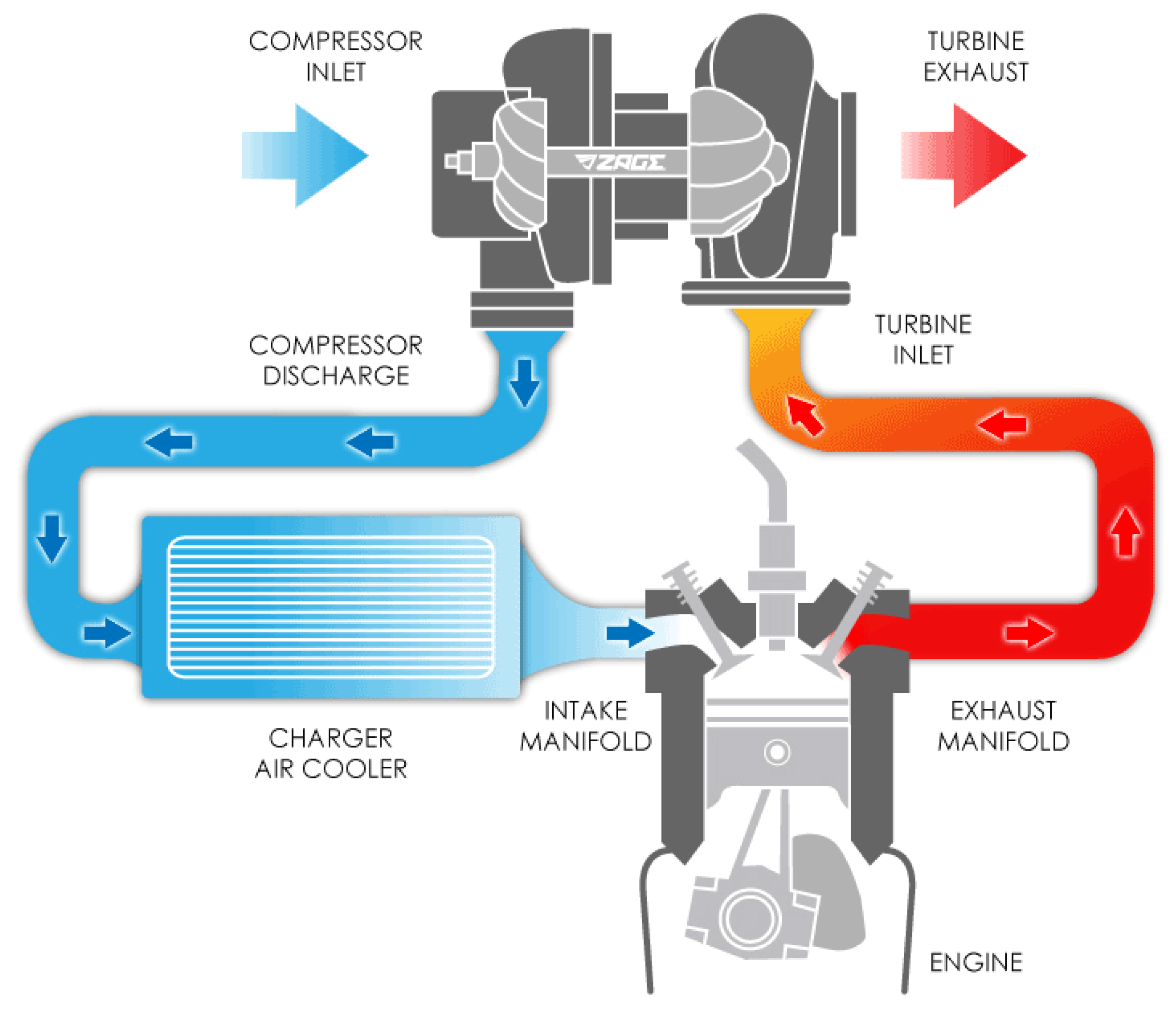
Figure 1. Connection between turbocharger and engine [4].
Preprints 98394 g001
Figure 2. Turbocharger block diagram [7].
Preprints 98394 g002
Figure 3. Turbocharger assembly [10].
Preprints 98394 g003
Figure 4. Turbocharger components 1) The compressor; 2) The turbine; 3) The central part [10].
Preprints 98394 g004
Figure 5. Schematic of electric turbo compound [14].
Preprints 98394 g005
Figure 6. Construction solution - the location of the motor generator is not between the turbine and the compressor but before the compressor [20].
Preprints 98394 g006
Figure 7. Different manufacturer’s construction solution [23].
Preprints 98394 g007
Table 1. HET on a thermal engine vs classic turbocharger on a thermal engine.
HET on Thermal Engine Classic Turbocharger on Thermal Engine
Strengths - Improved engine responsiveness - Established technology
- Enhanced fuel efficiency - Proven performance in traditional engines
- Contribution to eco-friendly transportation solutions - Commonly used and understood in the industry
Weaknesses - Increased complexity in powertrain system - Turbo lag may be present
- Limited efficiency at lower engine speeds
- Maintenance challenges and costs
- Elevated overall vehicle cost
- Less energy recovery potential
Opportunities - Growing market for eco-friendly vehicles - Continuous improvement and optimization of traditional turbochargers
- Opportunities for further refinement in HET integration - Integration with advanced engine management systems
- Government incentives and fuel efficiency regulations - Adoption in emerging markets
Threats - Competition from fully electric vehicles - Evolving emission standards
- Consumer perceptions about hybrid system complexity - Potential market preference for electric propulsion
Table 2. HET on a thermal engine vs HET on a hybrid engine.
HET on Thermal Engine HET on Hybrid Engine
Strengths - Improved engine responsiveness - Enhanced synergy with hybrid systems
- Enhanced fuel efficiency - Optimized collaboration with electric motor
- Contribution to eco-friendly transportation solutions - Efficient energy recovery during deceleration
Weaknesses - Increased complexity in powertrain system - Technical challenges in coordination with hybrid components
- Maintenance challenges and costs
- Elevated overall vehicle cost
- Potential issues in transient response and torque delivery
- Specialized training required for technicians
Opportunities - Growing market for eco-friendly vehicles - Integration with advanced hybrid vehicle technologies
- Opportunities for further refinement in HET integration - Advancements in predictive maintenance technologies
- Government incentives and fuel efficiency regulations - Market demand for fuel-efficient hybrid systems
Threats - Competition from fully electric vehicles - Evolving hybrid technology standards
- Consumer perceptions about hybrid system complexity - Potential challenges in market acceptance
Disclaimer/Publisher’s Note: The statements, opinions and data contained in all publications are solely those of the individual author(s) and contributor(s) and not of MDPI and/or the editor(s). MDPI and/or the editor(s) disclaim responsibility for any injury to people or property resulting from any ideas, methods, instructions or products referred to in the content.
Copyright: This open access article is published under a Creative Commons CC BY 4.0 license, which permit the free download, distribution, and reuse, provided that the author and preprint are cited in any reuse.
Prerpints.org logo

Preprints.org is a free preprint server supported by MDPI in Basel, Switzerland.

Subscribe

© 2024 MDPI (Basel, Switzerland) unless otherwise stated