Submitted:
12 February 2024
Posted:
15 February 2024
You are already at the latest version
Abstract
Keywords:
1. Introduction
1.1. The Wankel Rotary Engine as a Range Extender for Electric Vehicles
1.2. CFD of Wankel Rotary Engines
1.2.1. RANS Simulation Examples
1.2.2. Large-Eddy Simulation Examples
1.3. Summary of Literature and Distillation of Research Sims
- Use LES to simulate a complete cycle of a Wankel engine, including combustion, and with an approach that ensures a high-quality mesh throughout the cycle.
- Design and simulate a novel jet ignition system specifically tailored to Wankel engines.
- Explore the thermal efficiency benefits of a two-stage Wankel-based rotary engine.
2. Experimental and Computational Methods
2.1. Engine Testing
2.2. Computational Model
2.2.1. CFD Domain and Mesh
2.2.2. Turbulence Modelling
2.2.3. Simplified Combustion Model
3. Results
3.1. Experimental Validation
3.1.1. Motored Operation
3.1.2. Fired Operation
3.2. Tracking Turbulent Flow Structures Using the Q-Criterion
3.3. Flame Propagation
4. Discussion of Efficiency Enhancement Technologies
4.1. Pre-Chamber Turbulent Jet Ignition
4.1.1. Challenges for Pre-Chamber Turbulent Jet Ignition in Wankel Rotary Engines
4.1.2. Pressure-Connected Rre-Chambers for Active Scavenging and Cooling
4.1.3. The Two-Stage Rotary Engine
5. Conclusions
5.1. Conclusions Drawn from Results
5.1.1. 3D CFD Modelling of Wankel Rotary Engines
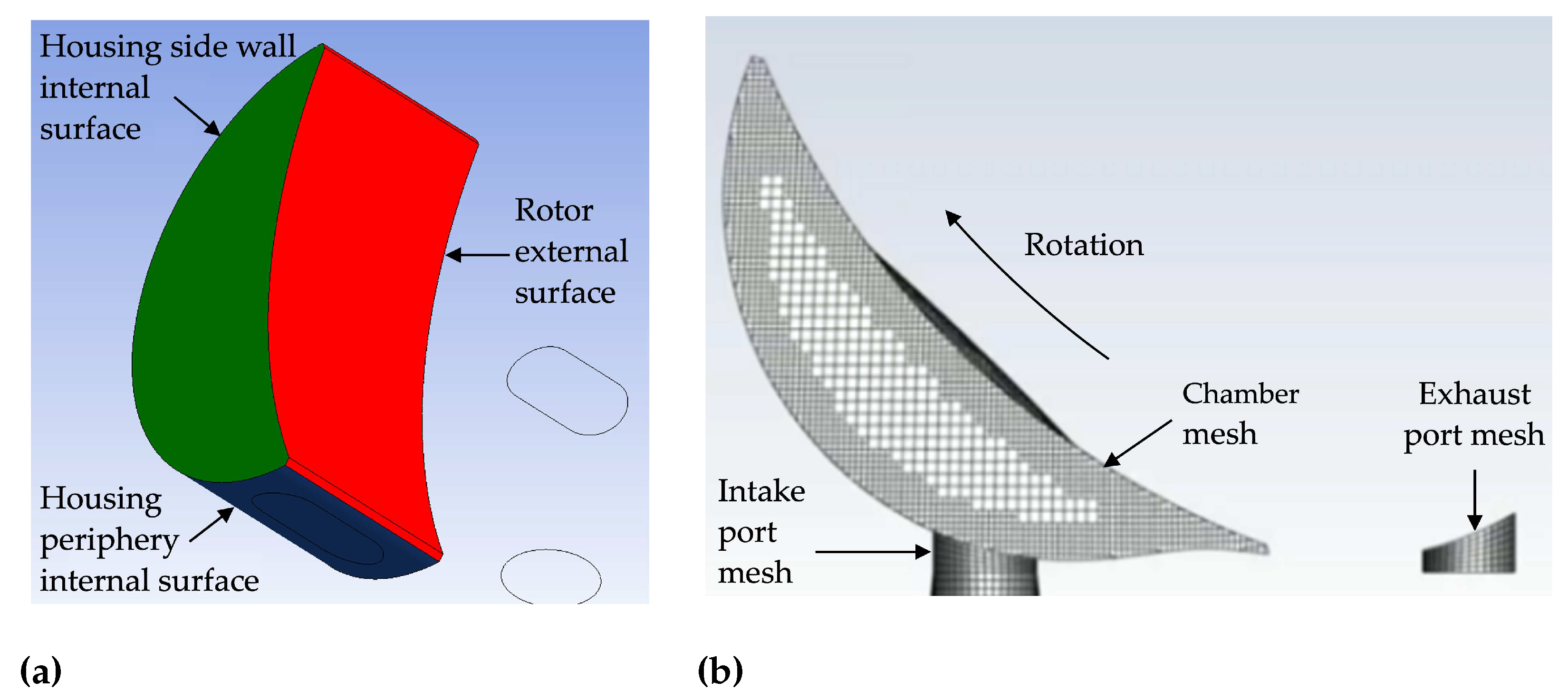
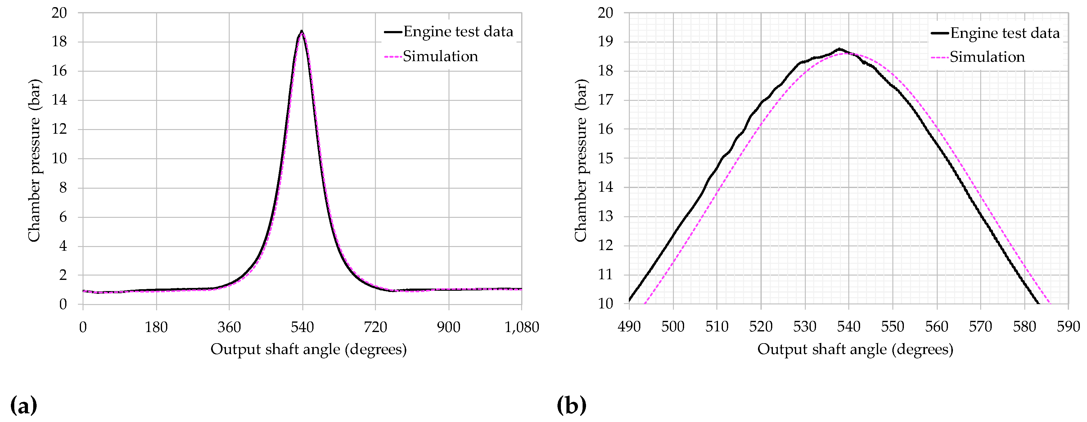
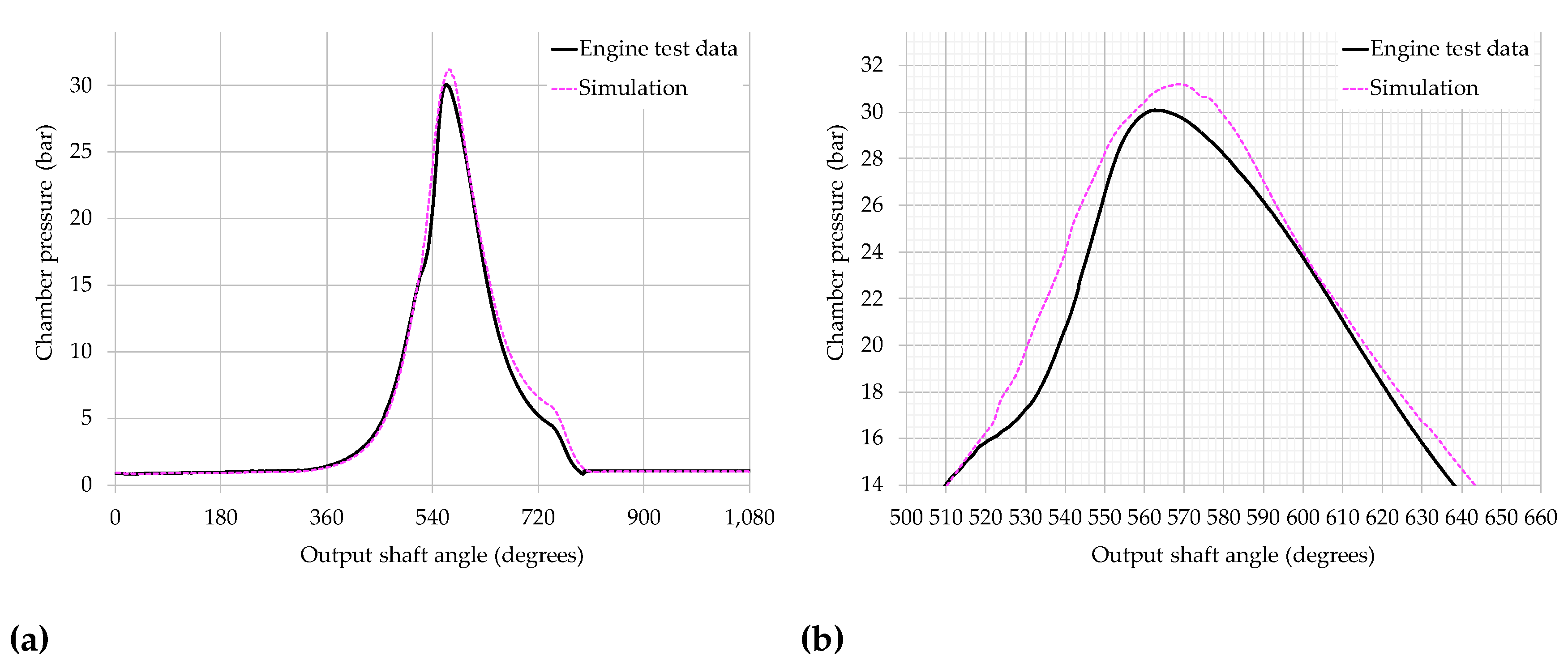
- Modelling the combustion chamber of a Wankel rotary engine using 3D CFD is not straightforward because it undergoes large changes in shape across an engine cycle, compared to a reciprocating piston engine. This research employed a bespoke dynamic meshing method to recreate the time-varying chamber volume and continuously changing shape, with simulation results of chamber pressure achieving very good validation against experimental test data. Although challenging, we may thus conclude that commercial 3D CFD software can faithfully simulate the compression, expansion, and gas exchange processes in a Wankel engine.
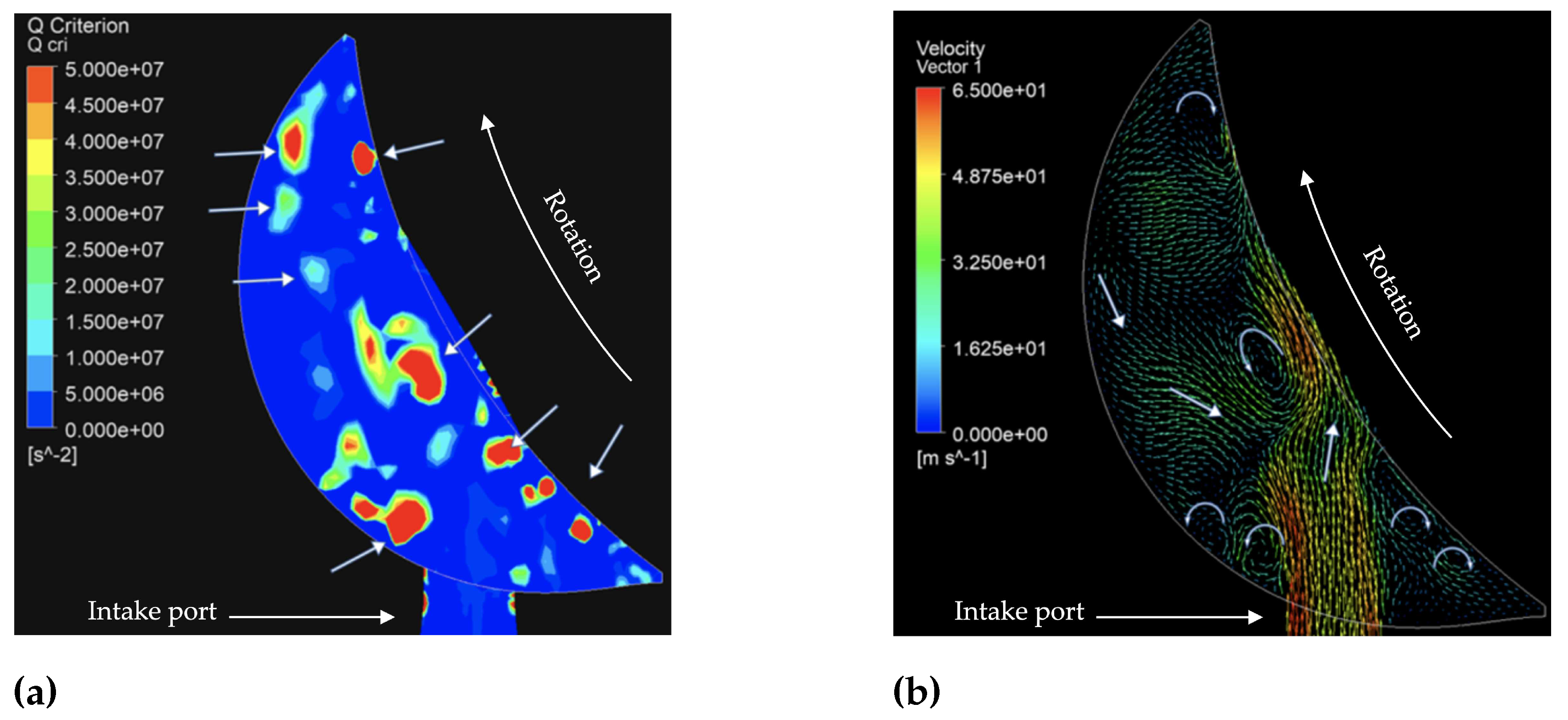
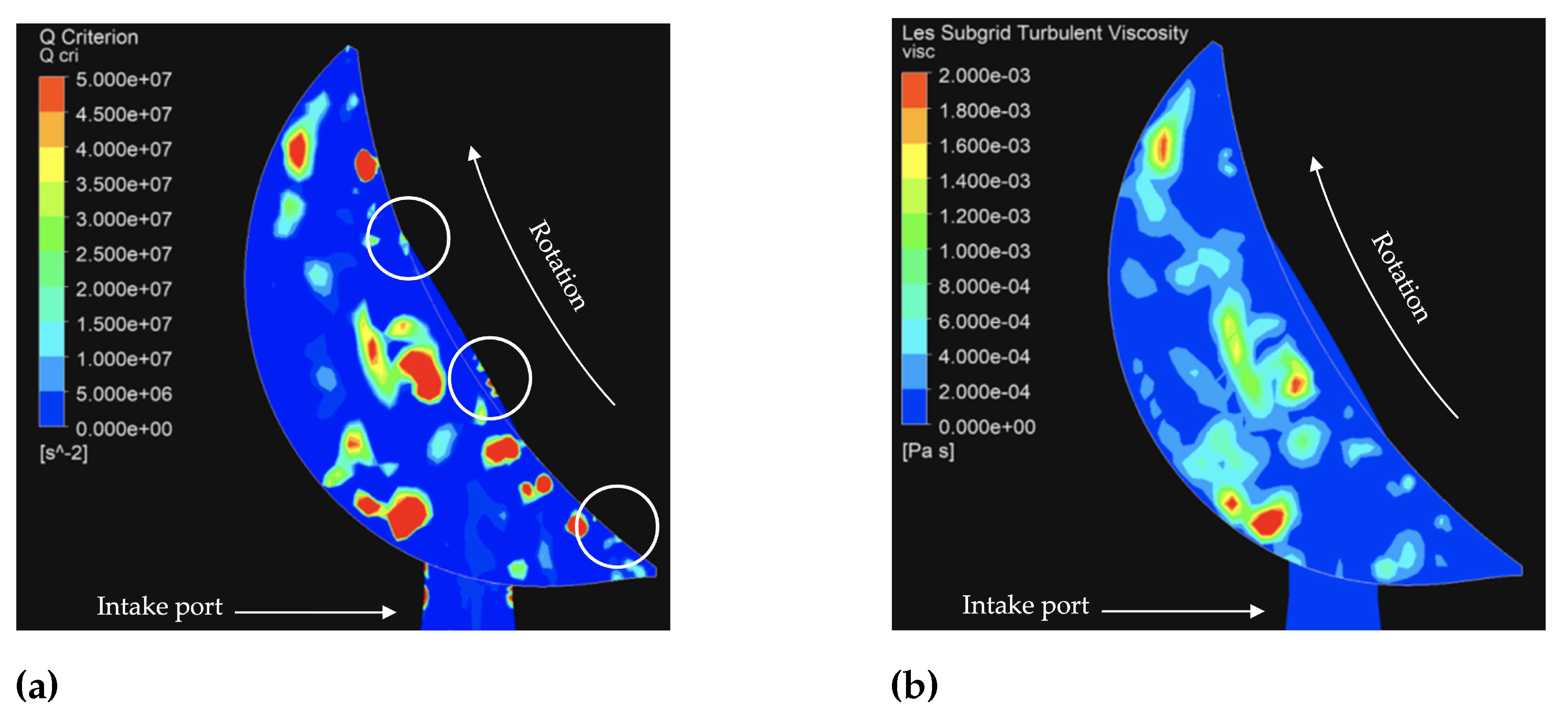
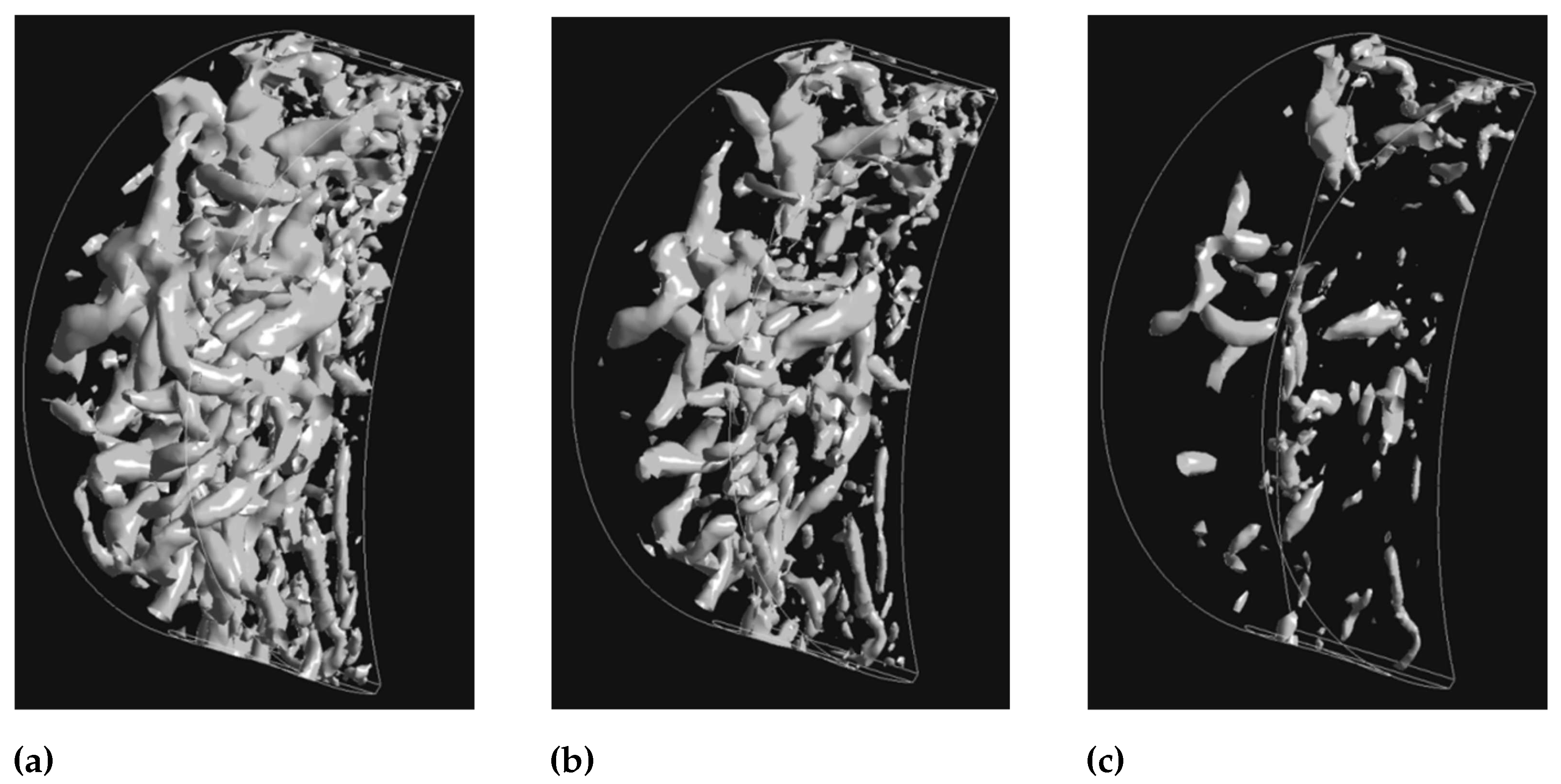
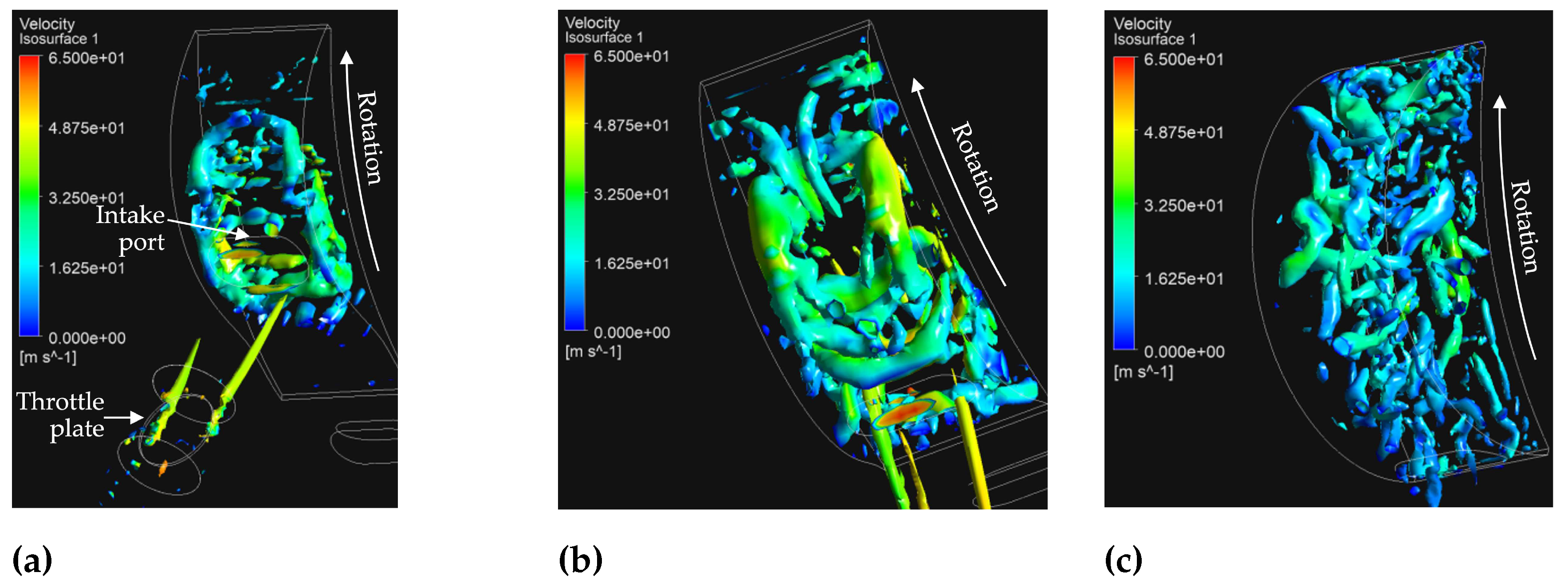
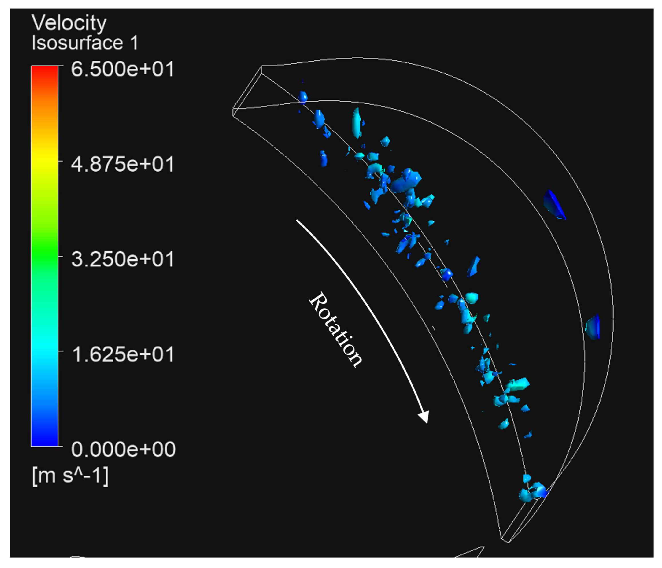
- In comparison to RANS CFD, LES offers more realistic modelling of turbulence production and dissipation and thus better prediction of the time-varying flow structures in a Wankel rotary engine. Resolving the complexity of these flow structures is essential for revealing the process of air-fuel mixture formation in the compression phase of the cycle, hence we conclude that LES-level simulations are required for sufficiently accurate performance and emissions predictions.
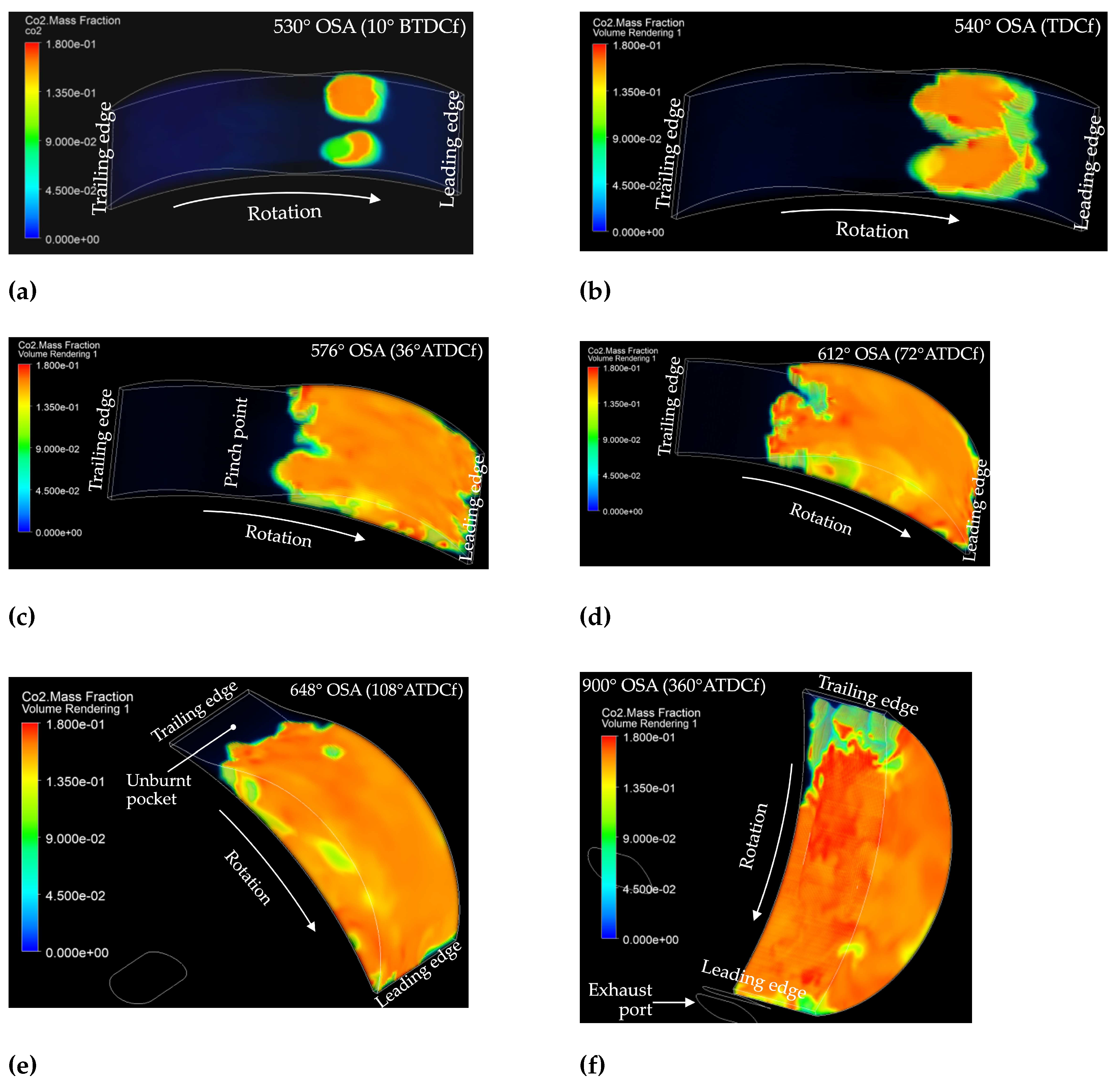
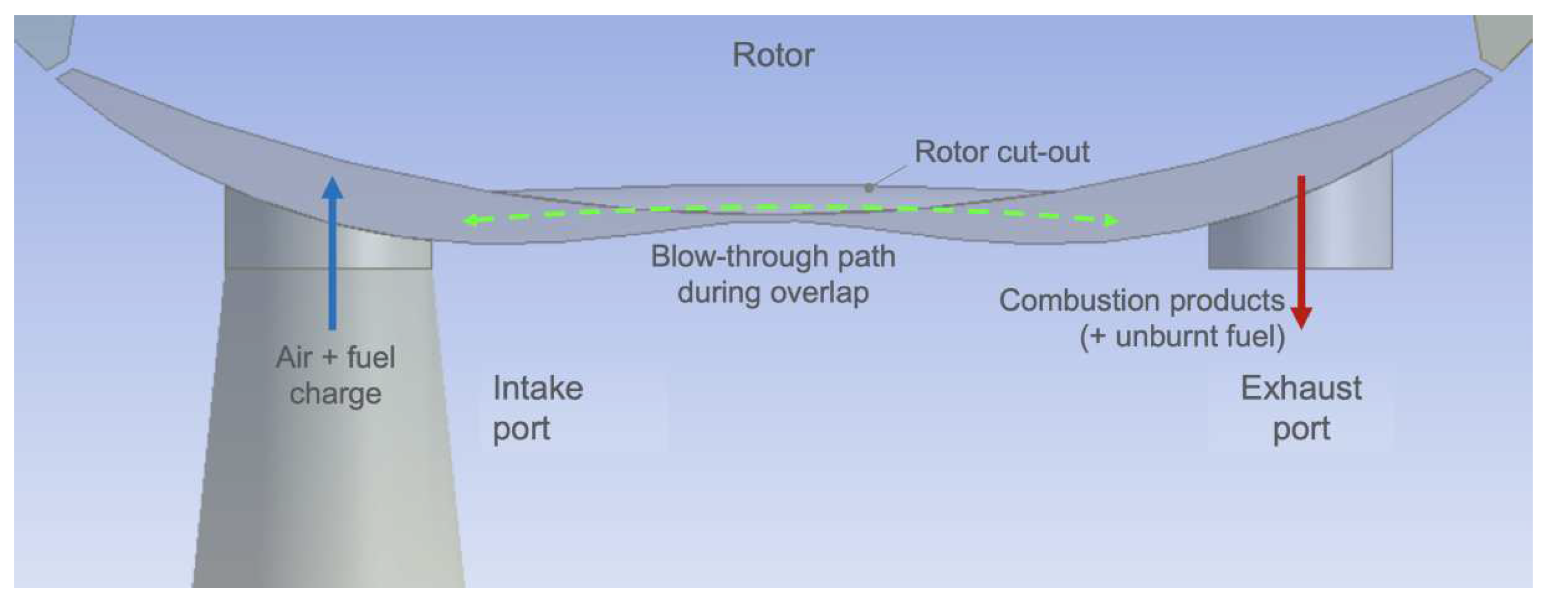
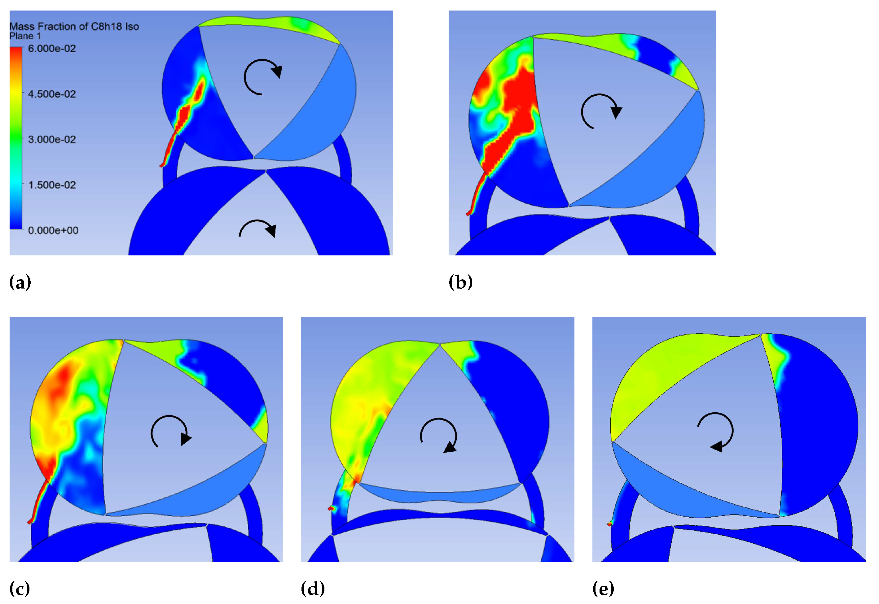
- Overall, Wankel engine performance and emissions are limited by some key design considerations. Combustion efficiency is primarily constrained by the "pinch point" and the elongated combustion chamber shape near TDC, and flame speed, which is low relative to combustion chamber length; these factors can give rise to regions of unburnt air-fuel mixture. While port overlap and its promotion of fuel blow-through is also detrimental for hydrocarbon emissions, it is of secondary importance here since it is not inherent in rotary engines and may be mitigated or avoided through design changes. Meanwhile, thermal efficiency is constrained by relatively low compression ratios, which are an unavoidable consequence of rotary engine geometry.
5.1.2. Addressing the Limiting Factors of Wankel Rotary Engines
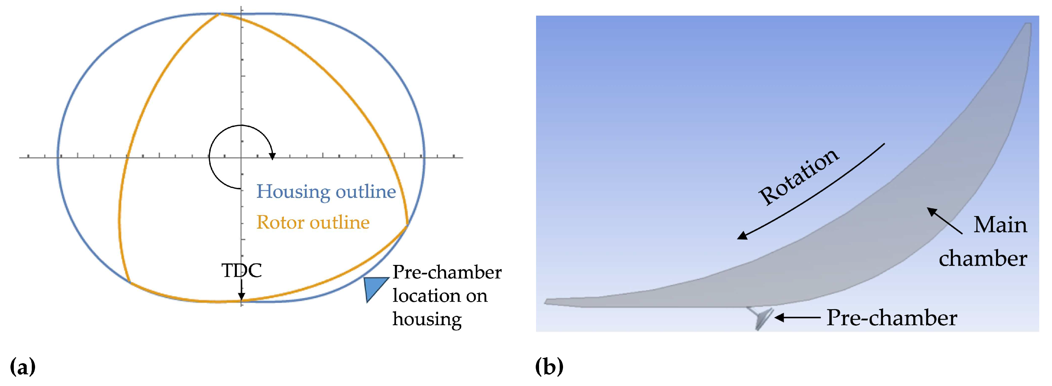
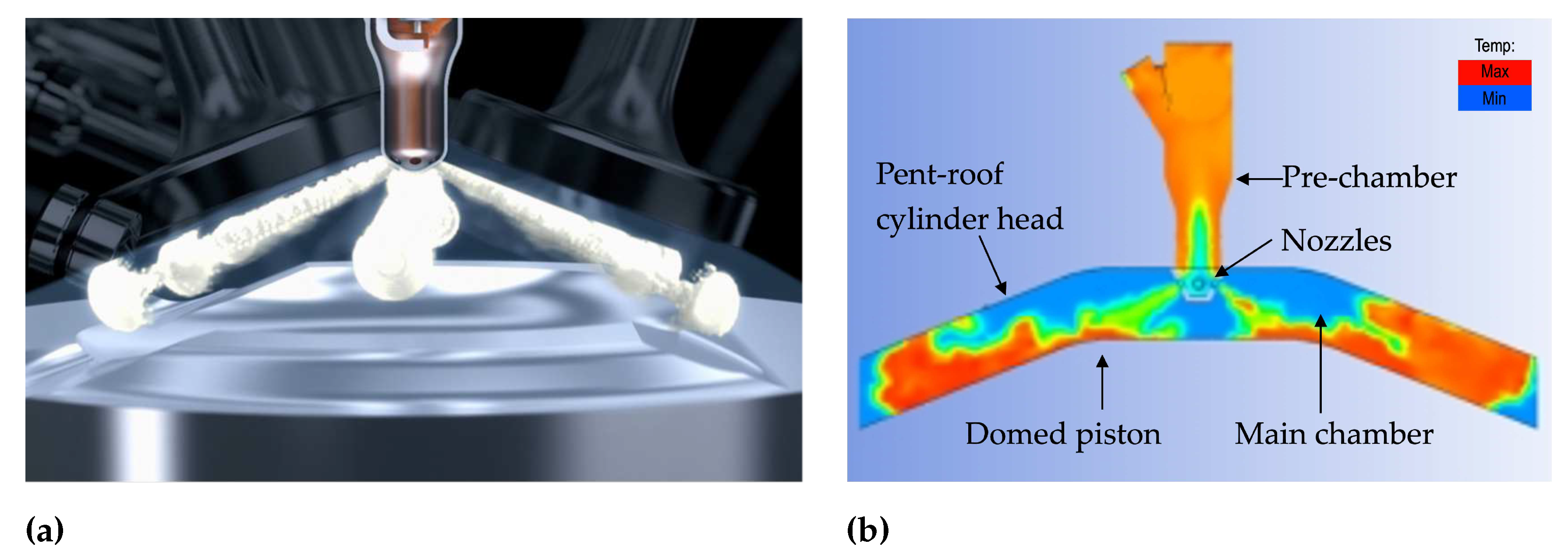
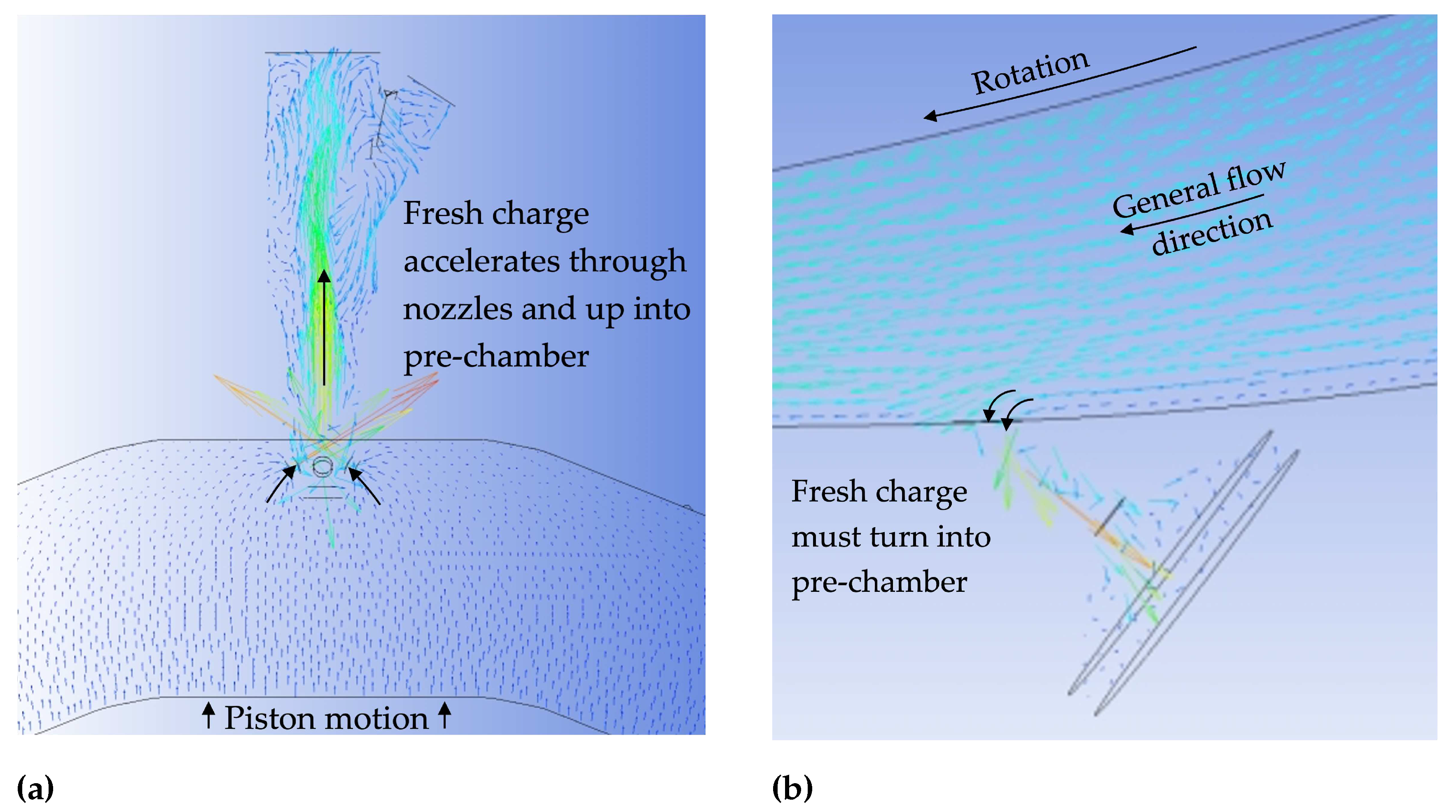
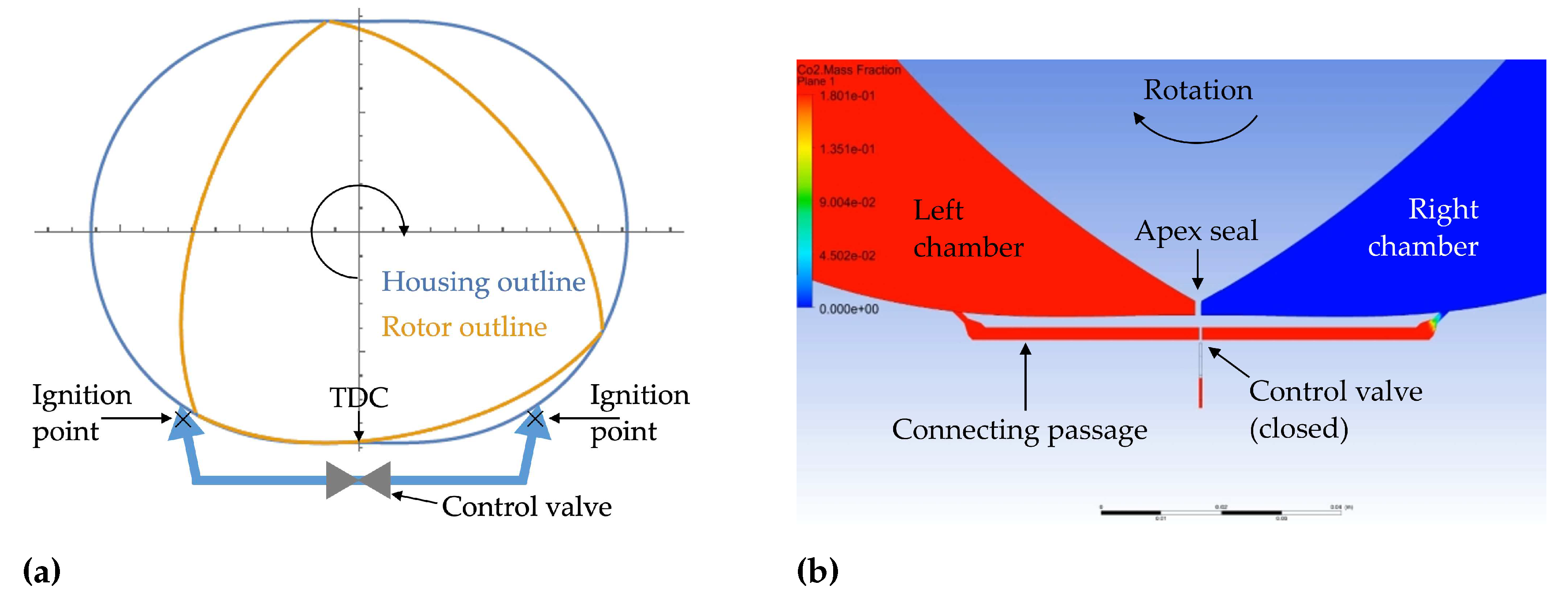
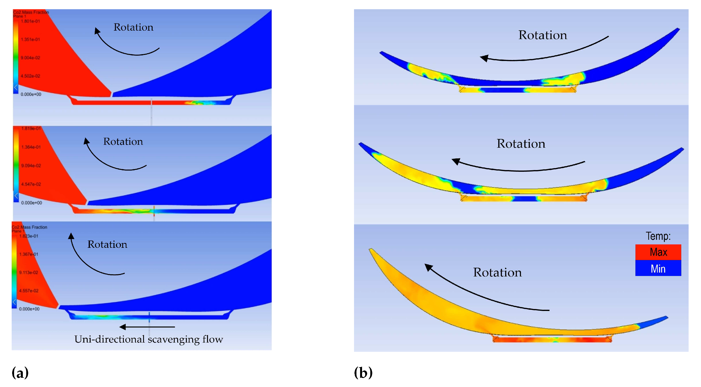
- Turbulent jet ignition applied to Wankel rotary engines has the potential to mitigate the combustion issues stemming from the elongated shape of the combustion chamber and a relatively low flame speed. However, it is not sensible to apply jet ignition without considering the fundamental differences between reciprocating and rotary engines. While the novel twin pre-chamber concept introduced and simulated here adds some complexity in the form of the connecting passage and its valve control, and a second nozzle, this configuration offers an implementation of pre-chamber turbulent jet ignition in Wankel rotary engines that improves combustion efficiency while avoiding the pitfall of poor pre-chamber scavenging.
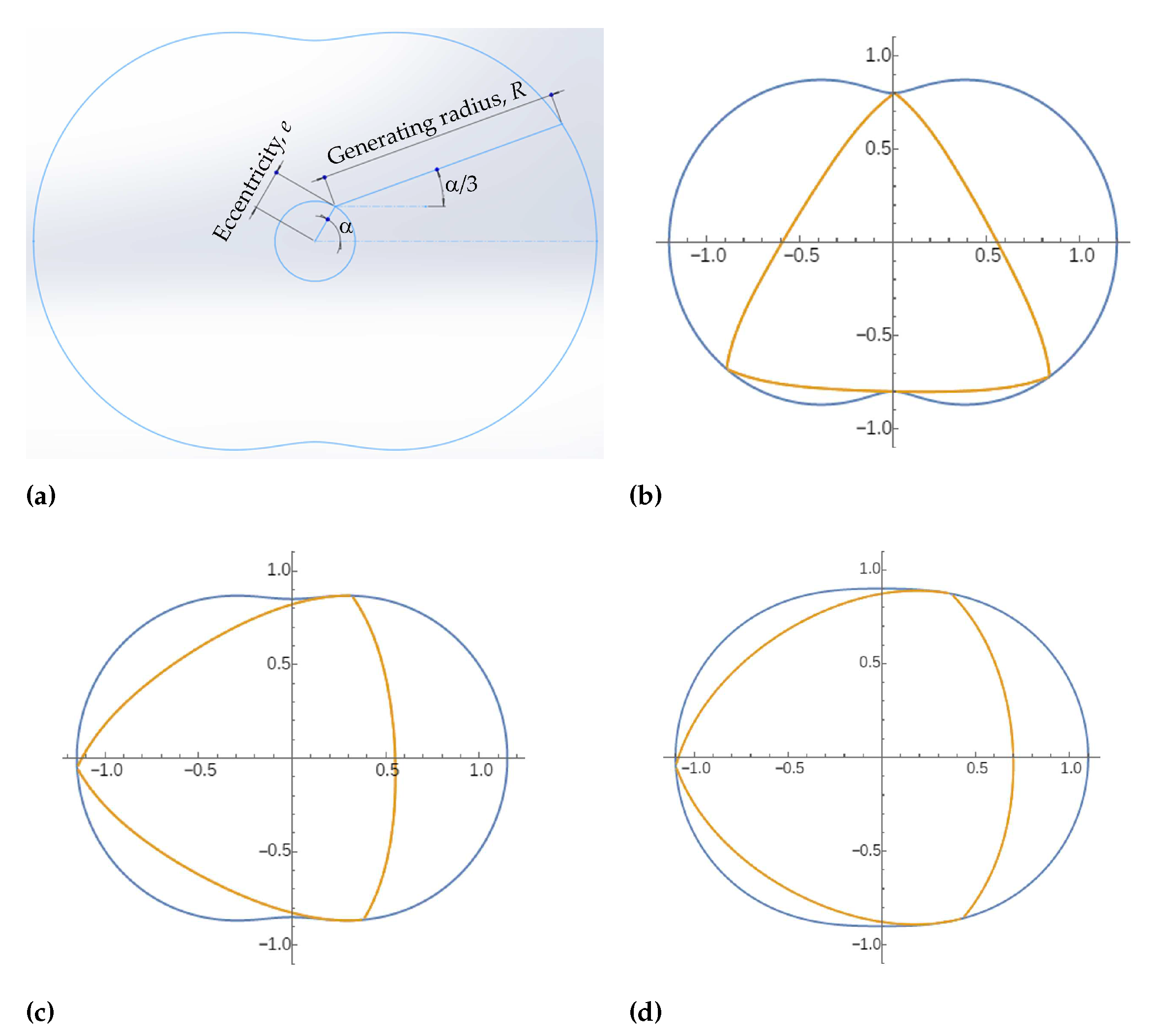
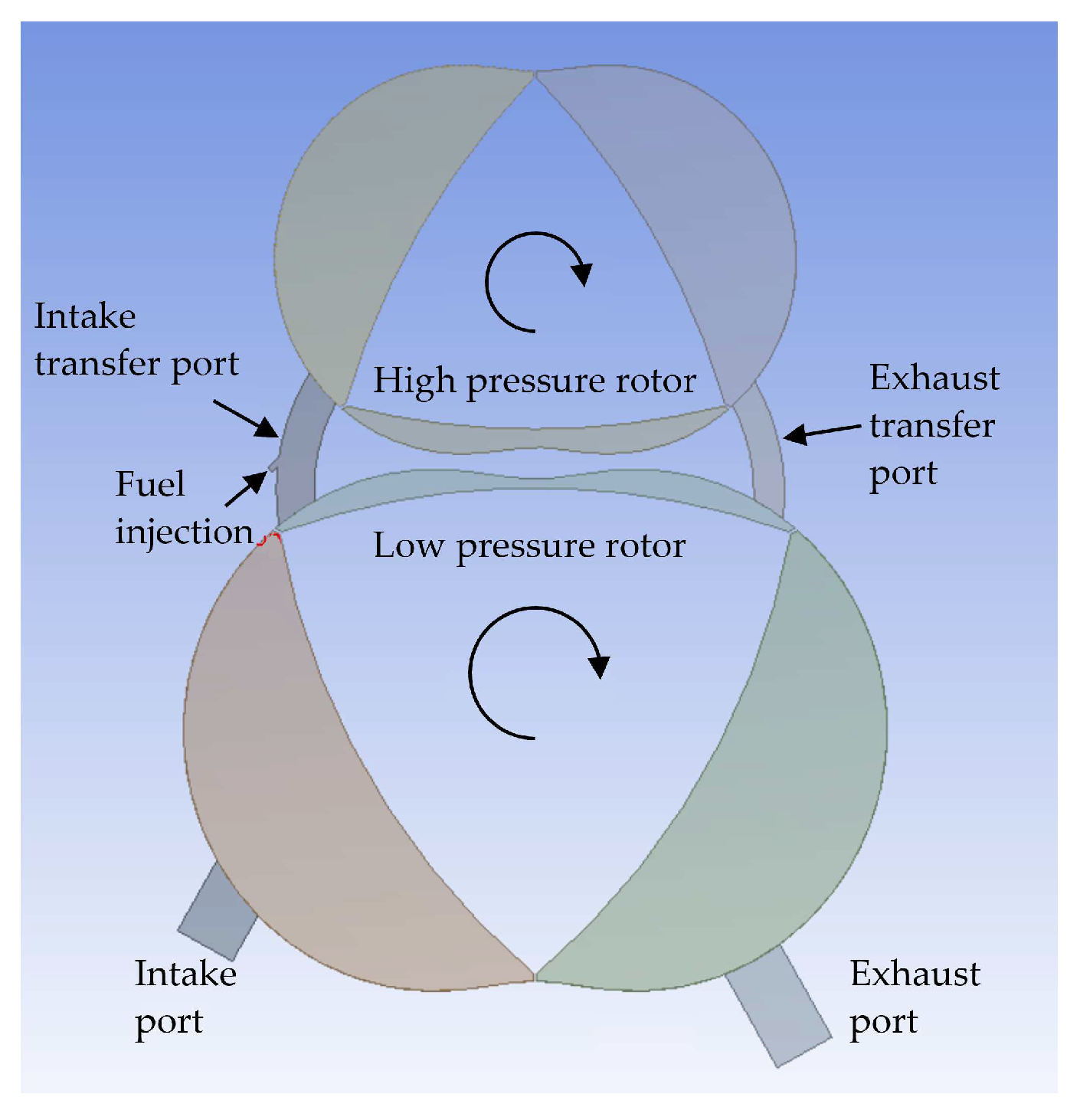
- A two-stage rotary engine, modelled on the Rolls-Royce “Cottage Loaf” prototype, affords the following advantages over a single-stage Wankel engine: (i) higher compression ratio and thus higher thermal efficiency; (ii) design freedom to avoid overlap between intake and exhaust ports, eliminating charge blow-through into the exhaust; and (iii) a larger gap between rotor and housing (because the system can afford to lose some compression ratio), which has been shown to help flame propagation across the pinch point. However, the increase in charge temperature due to two stages of compression and the losses imposed by the transfer port constrains the maximum realizable compression ratio due to raised knock propensity (when operating on gasoline); charge cooling would be beneficial for this reason. The two-stage design would also impose additional weight and packaging requirements. Such attributes would not seem to align with the goal for a small and lightweight range extender, but could be acceptable if used as the primary source of power.
5.1.3. Recommendations for Future Work
- The simulated ignition event is highly sensitive to local mesh refinement. But it would not be very computationally efficient to specify the level of mesh refinement required to faithfully capture ignition across the entire domain. This suggests a good use case for adaptive mesh refinement (AMR), which will locally refine (or coarsen) the mesh according to user-defined criteria, e.g., vorticity, reaction rate, or other parameters pertinent to the problem under investigation. AMR should be of course be implemented in future model improvements; it was not included in the currently reported work since, in the authors’ experience, combining dynamic meshing (for chamber motion) and adaptive mesh refinement proved problematic during simulation execution.
- Due to aforementioned computational power constraints, the combustion simulations used a highly simplified approach. These could be repeated, specifying a set of reactions and species that would enable prediction of exhaust emissions to an accuracy in line with engine dynamometer testing (which would provide the validation data).
- Wankel rotary engines are known for high power density, but it would be useful to explore the potential of turbocharging to raise power density even further. Turbocharging can be easily simulated at a basic level through appropriate modification of intake and exhaust boundary conditions.
- The pre-chamber jet ignition concept simulations should be repeated with finer mesh resolution to enable a quantitative assessment of the technology, with a view to specifying an experimental investigation.
Author Contributions
Funding
Data Availability Statement
Acknowledgments
Conflicts of Interest
Nomenclature
Roman symbols
| e | Eccentricity |
| Q | Q-criterion |
| R | Generating radius |
| S | Rate of strain |
Greek symbols
| Vorticity |
Abbreviations
| ABDC | After bottom dead centre |
| ACEA | European Automobile Manufacturers’ Association |
| AIE | Advanced Innovative Engineering |
| ATDC(f) | After top dead centre (firing) |
| BBDC | Before bottom dead centre |
| BEV | Battery electric vehicle |
| BSFC | Brake specific fuel consumption |
| BTDC(f) | Before top dead centre (firing) |
| CFD | Computational fluid dynamics |
| DES | Detached-eddy simulation |
| EFTA | European Free Trade Association |
| FCEV | Fuel cell electric vehicle |
| HC | Hydrocarbon |
| HEV | Hybrid electric vehicle |
| HPC | High performance computing |
| IC | Internal combustion |
| LES | Large eddy simulation |
| NVH | Noise, vibration, harshness |
| ORC | Organic Rankine cycle |
| OSA | Output shaft angle |
| RANS | Reynolds-averaged Navier-Stokes |
| REEV | Range-extended electric vehicle |
| SPARCS | Self pressurizing air rotor cooling system |
| TDCf | Top dead centre (firing) |
| TJI | Turbulent jet ignition |
| UAV | Unmanned aerial vehicle |
References
- ACEA. New Car Registrations: +13.9% in 2023; Battery Electric 14.6% Market Share. Available online: https://www.acea.auto/pc-registrations/new-car-registrations-13-9-in-2023-battery-electric-14-6-market-share/ (accessed on 9 February 2024).
- Weymar, E.; Finkbeiner, M. Statistical Analysis of Empirical Lifetime Mileage Data for Automotive LCA. International Journal of Life Cycle Assessment 2016, 21, 215–23. [Google Scholar] [CrossRef]
- Kapoor, P.; Costall, A.W.; Sakellaridis, N.; Lammers, R.; Buonpane, A.; Guilain, S. Multi-Objective Optimization of Turbocharger Turbines for Low Carbon Vehicles using Meanline and Neural Network Models. Energy Conversion and Management: X 2022, 15, 100261. [Google Scholar] [CrossRef]
- Emissions Analytics. The Inevitability of Hybridisation? Available online: https://www.emissionsanalytics.com/news/the-inevitability-of-hybridisation (accessed on 9 February 2024).
- Ziółkowski, A.; Fuć, P.; Jagielski, A.; Bednarek, M.; Konieczka, S. Comparison of the Energy Consumption and Exhaust Emissions between Hybrid and Conventional Vehicles, as well as Electric Vehicles Fitted with a Range Extender. Energies 2023, 16, 4669. [Google Scholar] [CrossRef]
- Yamamoto, K. Rotary Engine; Sankaido Co., Ltd., 1981.
- Uefuji, W.; Nishigouchi, K.; Okada, J.; Matsuda, Y.; Nobumoto, S.; Sato, M. Introduction of MX-30 Rotary-EV. Mazda Technical Revoew 2023, 40, 47–51. [Google Scholar]
- Morimoto, H.; Miyamoto, T.; Nakajima, K.; Kikuchi, T.; Tanaka, K.; Sunagare, Y.; Nomoto, T.; Wakabayashi, Y. Combustion Technology for 8C New Rotary Engine. Mazda Technical Revoew 2023, 40, 52–58. [Google Scholar]
- Turner, J.W.G.; Turner, M.; Islam, R.; Shen, X.; Costall, A.W. Further Investigations into the Benefits and Challenges of Eliminating Port Overlap in Wankel Rotary Engines. SAE Technical Paper 2021-01-0638, 2021. [CrossRef]
- Garrett Motion Inc. World’s First Commercial Diesel Engine with Brake Thermal Efficiency Above 50. Available online: https://www.garrettmotion.com/news/newsroom/article/worlds-first-commercial-diesel-engine-with-brake-thermal-efficiency-above-50-launched-by-weichai-boosted-by-garrett/ (accessed on 9 February 2024).
- Shi, C.; Ji, C.; Wang, S.; Yang, J.; Ma, Z.; Xu, P. Assessment of Spark-Energy Allocation and Ignition Environment on Lean Combustion in a Twin-Plug Wankel Engine. Energy Conversion and Management 2020, 209, 112597. [Google Scholar] [CrossRef]
- Spreitzer, J.; Zahradnik, F.; Geringer, B. Implementation of a Rotary Engine (Wankel Engine) in a CFD Simulation Tool with Special Emphasis on Combustion and Flow Phenomena. SAE 2015 World Congress & Exhibition. SAE Technical Paper 2015-01-0382, 2015. [CrossRef]
- Boretti, A.; Jiang, S.; Scalzo, J. A Novel Wankel Engine Featuring Jet Ignition and Port or Direct Injection for Faster and More Complete Combustion Especially Designed for Gaseous Fuels. 2015. [CrossRef]
- Sadiq, G.; Tozer, G.; Al-Dadah, R.; Mahmoud, S. CFD Simulations of Compressed Air Two Stage Rotary Wankel Expander — Parametric Analysis. Energy Conversion and Management 2017, 142, 42–52. [Google Scholar] [CrossRef]
- Celik, I.; Yavuz, I.; Smirnov, A. Large Eddy Simulations of In-Cylinder Turbulence for Internal Combustion Engines: A Review. International Journal of Engine Research 2001, 2, 119–148. [Google Scholar] [CrossRef]
- Zhang, Y.; Liu, J.; Zuo, Z. The Study of Turbulent Fluctuation Characteristics in a Small Rotary Engine with a Peripheral Port based on the Improved Delayed Detached Eddy Simulation Shear-Stress Transport (IDDES-SST) Method. Energies 2018, 11, 642. [Google Scholar] [CrossRef]
- Spalart, P.R.; Jou, W.H.; Strelets, M.; Allmaras, S.R. Comments on the Feasibility of LES for Wings, and on a Hybrid LES/RANS Approach. First AFOSR International Conference on DNS/LES, 1997, pp. 137–147.
- Poojitganont, T.; Sinchai, J.; Watjatrakul, B.; Berg, H.P. Numerical Investigation of In-Chamber Flow inside a Wankel Rotary Engine. IOP Conference Series: Materials Science and Engineering 2019, 501, 012043. [Google Scholar] [CrossRef]
- Bailey, N.; Louthan, L. The Compact SPARCS Wankel Rotary Engine. JSAE 2015 Congress. JSAE Technical Paper 2015 4346, 2015. [Google Scholar]
- Advanced Propulsion Centre, UK. 225CS - 40BHP - Wankel Rotary Engine. Available online: https://www.aieuk.com/225cs-40bhp-wankel-rotary-engine (accessed on 8 February 2024).
- Advanced Propulsion Centre, UK. Westfield – ADAPT: Reducing Vehicle Carbon Emissions through Development of a Compact, Efficient, and Intelligent Powertrain. Available online: https://www.apcuk.co.uk/portfolio/westfield-adapt (accessed on 8 February 2024).
- Vorraro, G.; Turner, M.; Turner, J.G. Testing of a Modern Wankel Rotary Engine — Part I: Experimental Plan, Development of the Software Tools and Measurement Systems. SAE Technical Paper 2019-01-0075, 2019. [CrossRef]
- Martini, H.; Montejano, L.; Oliveros, D. Bodies of Constant Width: An Introduction to Convex Geometry with Applications; Birkhäuser Cham, 2019. [CrossRef]
- Shen, X.; Costall, A.; Turner, M.; Islam, R.; Ribnishki, A.; Turner, J.; Vorraro, G.; Bailey, N.; Addy, S. Large-Eddy Simulation of a Wankel Rotary Engine for Range Extender Applications. International Conference on Powertrain Systems for Net-Zero Transport. Institution of Mechanical Engineers, 2021.
- Nicoud, F.; Ducros, F. Subgrid-Scale Stress Modelling Based on the Square of the Velocity Gradient Tensor. Flow, Turbulence and Combustion 1999, 62, 183–200. [Google Scholar] [CrossRef]
- Shen, X. Enhancing the Efficiency of a Rotary Thermal Propulsion System through Advanced Simulation Techniques. PhD thesis, University of Bath, 2023.
- Vorraro, G.; Turner, J.W.G.; Brace, C.J. Testing of a Modern Wankel Rotary Engine — Part II: Firing Condition Analysis. SAE Technical Paper 2022-01-0592, 2022. [CrossRef]
- Vorraro, G.; Turner, J.W.G.; Akehurst, S. Testing of a Modern Wankel Rotary Engine — Part III: Motoring Analysis. SAE Technical Paper 2022-01-0591, 2022. [CrossRef]
- Hunt, J.C.R.; Wray, A.A.; Moin, P. Eddies, Streams, and Convergence Zones in Turbulent Flows. Summer Program, Center for Turbulence Research, 1988, pp. 193–208.
- Zhan, J.M.; Li, Y.T.; Onyx Wai, W.H.; Hu, W.Q. Comparison Between the Q Criterion and Rortex in the Application of an In-Stream Structure. Physics of Fluids 2019, 31, 121701. [Google Scholar] [CrossRef]
- Cooper, A.; Harrington, A.; Bassett, M.; Reader, S.; Bunce, M. Application of the Passive MAHLE Jet Ignition System and Synergies with Miller Cycle and Exhaust Gas Recirculation. SAE Technical Paper 2020-01-0283, 2020. [CrossRef]
- Bigalli, S.; Catalani, I.; Balduzzi, F.; Matteazzi, N.; Agostinelli, L.; Luca, M.D.; Ferrara, G. Numerical Investigation on the Performance of a 4-Stroke Engine with Different Passive Pre-Chamber Geometries using a Detailed Chemistry Solver. Energies 2022, 15, 4968. [Google Scholar] [CrossRef]
- MAHLE Jet Ignition. Available online: https://www.mahle-powertrain.com/en/experience/mahle-jet-ignition/ (accessed on 30 January 2024).
- Kelman, T. Wankel Rotary Engine: Epitrochoidal Envelopes. Available online: https://demonstrations.wolfram.com/WankelRotaryEngineEpitrochoidalEnvelopes/ (accessed on 7 February 2024).
- Feller, F. The 2-Stage Rotary Engine — A New Concept in Diesel Power. Proceedings of the Institution of Mechanical Engineers 1970, 185, 139–158. [Google Scholar] [CrossRef]
- Turner, J.W.G.; Turner, M.; Vorraro, G.; Thomas, T. Initial Investigations into the Benefits and Challenges of Eliminating Port Overlap in Wankel Rotary Engines. SAE Technical Paper 2020-01-0280, 2020. [CrossRef]
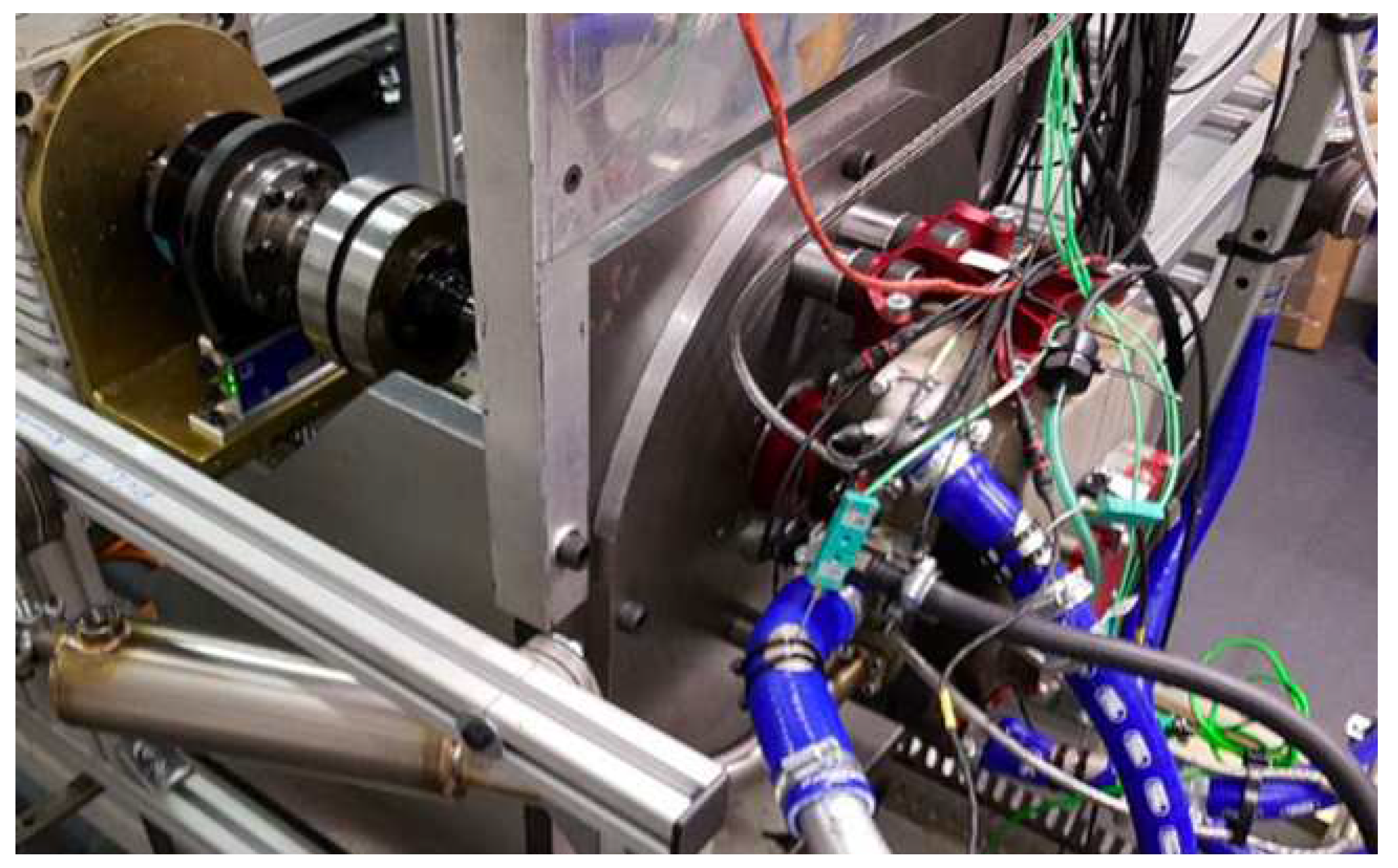


| Parameter | Value | Units |
|---|---|---|
| Generating radius (rotor) | 69.5 | mm |
| Generating radius (housing) | 71.5 | mm |
| Eccentricity | 11.6 | mm |
| Number of rotors | 1 | - |
| Displacement | 225 | cm3 |
| Compression ratio | 9.6 | - |
| Intake port opens | 71 | °BTDC |
| Intake port closes | 60 | °ABDC |
| Exhaust port opens | 69 | °BBDC |
| Exhaust port closes | 57 | °ATDC |
| Number of spark plugs | 2 | - |
| Ignition timing | 18 | °BTDC |
Disclaimer/Publisher’s Note: The statements, opinions and data contained in all publications are solely those of the individual author(s) and contributor(s) and not of MDPI and/or the editor(s). MDPI and/or the editor(s) disclaim responsibility for any injury to people or property resulting from any ideas, methods, instructions or products referred to in the content. |
© 2024 by the authors. Licensee MDPI, Basel, Switzerland. This article is an open access article distributed under the terms and conditions of the Creative Commons Attribution (CC BY) license (http://creativecommons.org/licenses/by/4.0/).


