
You are currently viewing a beta version of our website. If you spot anything unusual, kindly let us know.
Preprint
Article
A HBIM Approach for Structural Diagnosis and Intervention Design in Heritage Structures: The Case of the Certosa Di Pisa
Altmetrics
Downloads
137
Views
60
Comments
0
A peer-reviewed article of this preprint also exists.


This version is not peer-reviewed
Abstract
In the conservation of monumental heritage, the collection and utilization of information are of primary importance. The Heritage Building Information Modeling (HBIM) procedure harnesses the potential of three-dimensional models, offering significant advantages in accessing documentation, interoperability, multidimensionality of intervention design, cost evaluation and maintenance management. Attention here is focused on the Certosa di Pisa, a large historical complex built in the 14th century as a monastery of the Carthusian order, currently in a state of deterioration and in need of restoration and re-functionalization. The multifaceted nature of this monumental complex, with its intricate interplay of architectural elements spanning different historical periods and featuring diverse techniques, poses a significant challenge for structural safety assessment. This case study presents an opportunity to explore an HBIM approach to streamline the diagnostic process and facilitate the intervention design phase. The goal is achieved by utilizing an accurate 3D model enriched with data from multiple sources and automating certain operations for structural assessment. The usefulness of the HBIM methodology is highlighted as a valuable tool in the realm of Cultural Heritage structures for both technicians and scholars alike.
Keywords:
Subject: Engineering - Architecture, Building and Construction
1. Introduction
In recent decades, significant progress has been made in the field of two- and three-dimensional digital representation, enabling the acquisition of precise models for documenting existing architectural heritage. 3D models generation can be achieved through various techniques, including solid modeling, which can be handled directly or parametrically controlled, as well as meshes created through triangulation of point cloud coordinates [1]. These different techniques are typically used in combination, as none of them individually can guarantee high levels of accuracy, automation, realism, and model manipulation capabilities, while ensuring cost and time efficiency for surveying and processing [2]. There are many examples showing the application of these techniques in the field of cultural heritage, facilitating the high-resolution reproduction of historical structures and objects, as well as the development of integrated interfaces for documentation and presentation of multimedia content [3].
Contemporary systems not only allow representation but also the possibility to enrich 3D models with additional information, thus enabling the creation of ontological models [4,5]. However, when it comes to historic buildings, more research efforts are needed to effectively manage the numerous and diverse information regarding the construction history, transformations, materials, and state of conservation. A potential solution to address these challenges is provided by Building Information Modeling (BIM) systems. BIM does not refer to a specific object, namely the 3D model, or software, but rather denotes a collaborative process for producing and managing structured digital information. The goal is to create a shared database that goes beyond traditional representations, constituting a semantically enriched model that centralizes the collection and exchange of information between stakeholders throughout the entire life cycle of construction [6].
The application of the BIM process in the context of heritage buildings is known as Heritage or Historical BIM (HBIM) [7]. HBIM involves modeling building elements as parametric objects in a database library and processing large amounts of data from various sources. While BIM is well established in the new construction sector, its use in historic building contexts is relatively new, but progressively expanding due to its significant advantages, such as quick access to documentation, interoperability in the analysis, multidimensionality in the design phase, ease of cost assessment at each stage and improved management of maintenance and interventions [8,9]. In fact, having an informed digital model of the building enables experts to have a comprehensive view that is the starting point to identify structural and conservation deficiencies and to simulate different scenarios of intervention.
Unlike the BIM process, which leverages the combination of elements chosen from a library usually already possessing information, HBIM implies the creation of a model of the construction, to which data is subsequently associated. The HBIM process primarily involves a reverse-engineering operation that transforms survey data into a digital representation of the structure. This process generally consists of three stages: information acquisition, which entails surveying the geometry and relevant features; information processing, which involves creating the actual proprietary model; and data fusion, which incorporates additional information into the model. During this final stage, the potential of the HBIM process for information management in historic architectures becomes evident. The model can systematically incorporate both quantitative and qualitative data, allowing for easy extraction when needed. Furthermore, the ability to accommodate diverse data types and sources promotes collaboration among professionals working on the same asset in different capacities. A comprehensive and well-organized catalog of gathered data can play a vital role in different aspects of building restoration and management, offering valuable assistance, especially during operational phases [10]. This information often spans various disciplinary domains, and correlating diverse data sets can streamline the generation of analyses. Furthermore, the potential exists to employ a dynamic model that remains continually updatable and expandable, fostering collaboration among professionals in different roles [11]. The utilization of semantically enriched 3D elements enables navigation through the model accompanied by data such as photographs, links, descriptions, and 2D drawings. Additionally, querying the model facilitates the creation of thematic maps [12]. This comprehensive approach serves as an effective solution for synthesizing, organizing, and storing information, which is essential for knowledge acquisition and decision-making in conservation projects. In this interdisciplinary setting, HBIM methodologies emerge as a promising and efficient tool for the preservation of historical assets [13]. They provide an effective approach to understanding, preserving, and restoring historical architecture, with the potential for centralized management of all documentation. In recent years, some experiments have been conducted in this regard [14,15,16,17]. Works have demonstrated the advantages of applying the method to complex and multilayered historical buildings, highlighting the transformations caused by restoration work. In [18], an application for studying the architectural history and conservation status of the Cathedral of St. John the Theologian in Nicosia, Cyprus, is presented, while [15] focuses on managing non-geometric information in Historic Building Information Modeling (HBIM) and translating the traditional conservation procedure in the interesting case of the Cathedral of Parma.
The HBIM method has recently been used for preventive conservation [19], restoration project development, and structural analysis [19,20] of ancient constructions of various types and materials. Among these, we can mention its application to the ancient Library of Salamanca (Spain) for preventive conservation [19], the cloister of Saint-Guilhem-le-Désert (France) [21], and the Four Courts Palace (Ireland) [22], respectively, for surveying, representation, and sharing of architectural heritage.
In [23], HBIM is used for collecting and organizing data related to the degradation of existing wooden structures, and, more generally, in [24] the main literature contributions using HBIM for managing data from diagnostic activities and monitoring of existing structures and infrastructures are reported. Similarly, in [25], HBIM is applied for the control and monitoring of the structural safety of the ancient metal bridge O Barqueiro in Galicia. Finally, in [26] and [27], the digital representation of the built environment and the management of documentation are addressed, respectively, aiming for better utilization of BIM projects through the use of portable tools and the creation of as-built projects for structures and infrastructures.
The capabilities of integrating HBIM with GIS have also been explored [9], leveraging the strengths of this powerful tool that serves various purposes in geographic and urban contexts, including risk control, planning, analysis, and visualization [28]. For a comprehensive overview of the current state of HBIM implementation and research trends, [29] provides a valuable review of the existing literature.
At present, numerous BIM platforms are employed by professionals for tasks such as modelling, visualizing, assembling, and managing architectural heritage knowledge. However, despite the increasing applications of BIM technologies in HBIM workflows, the discipline still lacks a standardized approach to HBIM implementation. This limitation restricts the application of BIM technology and hinders the realization of associated benefits in the research and preservation of historical structures.
The present work is part of a preliminary study carried out by a multidisciplinary group of experts of the University of Pisa to evaluate the structural safety of the Certosa di Pisa, a monastery of the Carthusian order established in the XIV century. The monumental complex, currently in a state of severe deterioration, needs restoration and re-functionalization. This study, focused on the south-western section of the Certosa, offers the opportunity to explore the application of the Building Information Modeling (BIM) methodology. Emphasis is placed on the structural aspects, which require specific strategies to automate some operations for the safety assessment of the historic and artistic structures. The objective of this work is to find a methodology for synthesizing and organizing information, to identify critical issues, plan the necessary interventions and evaluate their technical feasibility. A procedural framework is established for carrying out the structural analyses through an operational process that can be easily extended to the entire Monumental Complex. The article outlines the fundamental phases of the realization of the model and highlights the characteristics that make it a valid tool in the knowledge acquisition phase and in the planning of consolidation and restoration interventions.
2. Materials and Methods
2.1. The Certosa di Pisa
The Certosa di Pisa is a large historical complex located in the Municipality of Calci, a small town near Pisa. In the Val Graziosa, on the slopes of Monte Pisano amidst olive and cypress trees (Figure 1a), the Certosa was originally established in 1366 as a monastery of the Carthusian order of San Bruno [30]. It underwent significant enlargement between the XVII and XVIII centuries, resulting in its current late Baroque appearance (Figure 1). Currently, the site is partially used by the University of Pisa, managing the Museum of Natural History, and partially by the Ministry of Culture, overseeing the National Museum of the Monumental Charterhouse of Calci.
The Complex comprises multiple buildings, each serving specific functions (Figure 2). The western façade houses a building known as Case Basse, which spans approximately 150 meters and consists of two above-ground stories. This structure hosted various services for the Charterhouse, including the pharmacy, San Sebastiano chapel, and the parlor, which were accessible to residents as well. In front of the Case Basse there is the cloistered monastery proper, an imposing three-story edifice with the main façade facing west, separated from the Case Basse by a large green area called Corte d’Onore. At the center of the complex there is the church, originally built for the exclusive use of the monks. The church features a grand double-ramp staircase, a magnificent façade covered in white marble and decorated on the tympanum by a statue of the Assumption surrounded by angels (Figure 2).
Next to the church there are the sacristy, the chapels, the Chapter House, the lodgings for the lay brothers, and the buildings dedicated to rural activities. At the rear of the church there is the Great Cloister (Chiostro Grande), lined with the fifteen cells of the monks (Celle dei Padri), as well as the worship rooms, the Refectory, and the Chapter House. Other cloisters in the south-western portion are the Capitolo Cloister (Chiostro del Capitolo), overlooked by the chapel, and the Granduca (or Foresteria) Cloister (Chiostro del Granduca o della Foresteria), surrounded by the dwellings of the lay brothers.
By around 1390, essential spaces for Carthusian life had been completed, including the church with several chapels, the chapter house, a portion of the monks’ cells in the Great Cloister, the cells for the lay brothers, the refectory, and the kitchens [31,32]. In the second half of the 14th century, there was a primarily decorative activity, which came to a halt at the end of the 15th century, when the monastery experienced a period of economic hardship due to renewed tensions between Pisa and Florence. In the early 17th century, a significant renovation phase ensued, involving modifications and expansions of the rooms around the Granduca Cloister, along with the addition of new cells in the Great Cloister. In this period, alterations were also made to the Case Basse, and a new entrance was created in line with the church.
The final significant construction phase that shaped the current appearance of the Certosa di Pisa took place in 1764. In this period, the Corte d’Onore was nearly doubled in size, a bell tower was erected (which remained unfinished) and a large granary was built in the northern area of the Complex. However, starting from 1809, the Carthusian community had to face increasingly unfavorable political and economic circumstances, which led to a deep crisis and the near cessation of building activities. Following the suppression of religious orders by Napoleon Bonaparte, the Certosa lost all its properties, and the monks were compelled to leave.
After the restoration of ecclesiastical communities by Leopold II, the Carthusians returned as secular monks, and some restoration work was carried out. However, after the definitive suppression of religious orders upon the establishment of the Kingdom of Italy, all assets were transferred to the State Property. Fortunately, the law recognized the immense value of the Monastic Complex, declaring it of monumental importance. This fact contributed to the preservation of the Certosa di Pisa from alterations by private individuals, unlike what happened to other Italian Carthusian monasteries.
In 1869, a portion of the Southern area was entrusted to the Royal Conservatory of Sant’Anna, resulting in some transformations that were later reversed. From 1871, for almost a century, the monks were allowed to remain in the monastery but were compelled to share the space with other institutions. In 1888, the Carthusian Monastery temporarily served as an artillery unit, and in 1915, the non-monastic portion was used as a barracks, followed in 1916 by a reserve hospital and from 1917 to 1919 by a hospital for prisoners of war of the Austro-Hungarian army. In 1972, the last monks definitively left the Carthusian hermitage, which in 1979 was partially assigned to the University of Pisa and transformed into a museum. Currently, the Complex is managed jointly by the University of Pisa, which occupies most of the rooms in the northern section as the Museum of Natural History, and by the Ministry of Culture, with the National Museum of the Monumental Certosa di Calci, which occupies most of the rooms in the southern section. The Celle dei Padri are managed by both administrations: the northern cells are under the supervision of the Ministry of Culture and the southern ones under the University of Pisa. The ground floor and the second floors of the monastery are mainly used as exhibition spaces accessible to the public, with some areas intended for storage and warehouses. Additionally, certain rooms on the second floor serve as offices for university staff, and there are accommodations available for staff members in the Case Basse.
At present, the buildings of the Certosa di Pisa are generally in a state of decay, with considerable deterioration in the wooden floors, roofs, and, in some cases, in the masonry materials. This deterioration is often caused by factors such as water infiltration from roofs or rising damp from the ground, both capable of significantly compromising the integrity of the masonry. Furthermore, the fragmentation of governance, stemming from the existence of two separate administrations, is having a detrimental impact on resolving these critical issues, ultimately exacerbating deterioration.
The University of Pisa recently acknowledged the necessity for restoring and re-functionalizing the entire Complex. They initiated an extensive study, engaging various expertise within the university. The south-western area was selected as a case study for a pilot project, focusing on the cenobitic region, the Granduca Apartments, the Granduca Cloister, and the Capitolo Cloister.
2.2. Investigation on the South-West Portion of the Certosa di Pisa
Investigating the structures of the monumental Complex required significant effort due to their large dimensions, numerous construction phases and transformations with various uses over time, as well as extensive decorative elements covering most surfaces. In 2018, a survey campaign was conducted, employing both manual techniques and laser scanners. Additionally, a series of on-site tests were planned and executed to identify the construction elements and their interconnections accurately. To achieve this, specific forms were prepared containing the test list, indicating the position and purpose of each test, describing the room where the test would occur, and recording the presence of decorative elements within it. The forms also included details about equipment, execution methods, estimated costs, and priority levels for each investigation. The survey aimed to characterize the main masonry typologies in the area, utilizing the Index of Masonry Quality (IQM) method [33] to estimate strength values for each masonry type. The materials identified include bricks for the vaults and walls, sandstone for the columns of the cloisters, and locally sourced stone, primarily quartzite from the nearby Monti Pisani, used for the general masonry. Three main masonry macro-categories were identified: stone masonry with a chaotic texture, mixed stone and brick masonry with chaotic texture, and brick masonry with lime mortar. Due to the limited number of tests, mapping the masonry was also done by analogy, where the identified masonry typology was extended to areas believed to belong to the same construction phase. A similar approach was also taken for vault types, as investigating their internal structure was often impractical. Additionally, connection deficiencies between wall panels at the interface of different construction phases were hypothesized and later verified through structural tests. Extensive explorations of the roofs were conducted, with attempts made to assess the physical and mechanical properties of the timber whenever feasible. Concurrently, load values were measured in approximately forty metal tie rods. This provided an opportunity to employ innovative techniques using acoustic measurement [34]. The investigation included analyzing crack and deformation patterns, creating a three-dimensional geometric model for exploration, and assessing material types and their continuity. These efforts greatly facilitated the identification of underlying causes of instability symptoms, structural deficiencies, potential active mechanisms, and primary vulnerabilities.
Based on these observations, intervention proposals were formulated, and additional structural tests were recommended to evaluate their feasibility. In this context, the HBIM played a crucial role by synthesizing all collected data and enabling its visualization on the three-dimensional model. The HBIM model has proven invaluable for synthesizing information and guiding decision-making regarding intervention strategies and further investigations.
2.3. Creation of the HBIM Model: A Workflow for Semantic Modeling and Data Fusion
The south-western portion of the Certosa covers approximately 40500 cubic meters. The creation of the HBIM model entailed three primary phases: information acquisition, data processing, and data fusion, all executed using Autodesk Revit and Autodesk AutoCAD software. The geometric survey conducted by the A.S.T.R.O. Laboratory at the University of Pisa primarily relied on a three-dimensional point cloud generated from the Leica Scan Station C10 laser scanner (Figure 3). In instances where supplementary information was required, manual surveys were conducted, complemented by archival research.
The point cloud data was imported into Autodesk ReCap for cleaning and segmentation, streamlining management and processing. Subsequently, each region of interest was exported in the rcp format compatible with Autodesk Revit. The digitized survey was seamlessly integrated with the direct geometric survey to improve accuracy, furnish references, conduct detailed surveys, and correct deficiencies in shaded areas.
Thematic data acquisition was conducted concurrently to align with the objectives of the HBIM model. This involved identifying the construction time of structural elements, determining masonry types, vault and floor types, assessing deterioration conditions and material pathologies, documenting the symptoms of instability of the structures, cracking and deformation patterns, and mapping the positions of performed in situ tests. A scan-to-BIM approach was employed, which entailed the creation, manipulation, and positioning of native BIM components in direct reference to the point cloud.
Due to the absence of software capable of automatically identifying shapes from the point cloud and the limitations in Revit’s capabilities for creating complex shapes, the construction of three-dimensional objects was primarily executed manually. This process involved generating parametric shapes on a case-by-case basis. Customized content was indispensable due to the unique nature of architectural heritage elements, unlike the standardized components typically found in new constructions. Freeform modeling programs, such as Autodesk AutoCAD, were utilized to model and mesh complex geometric elements like vaults and cracks.
For vaulted surfaces, 3D generating curves extracted from the point cloud were utilized to create surfaces, which were then processed and meshed (Figure 4). Each surface was individually modeled, resulting in a total of 205 units. This process involved tracing construction lines and creating an RFA ‘family’ up to its final placement within the structure. During this phase, the simplification of geometry inevitably led to a loss of information, such as irregularities on wall or vault surfaces. To address this, the three-dimensional points detected within the file were preserved, enabling useful comparisons with the simplified geometry when necessary (Figure 3c). The resulting model is depicted in Figure 3d. Once the geometry of all structure components was established, additional relevant data and information were incorporated in a structured manner, associating them with each individual BIM element. Following the processing phase, an extensive digital database was developed, compiling the documentation and information generated during the survey work, refined, and synthesized according to specific procedures.
The model, acting as a digital twin of the construction, was designed to receive and store any data relevant to itself. In contrast to a new construction project, where necessary parameters are typically pre-implemented in BIM software, incorporating customizable attributes is often required for existing buildings. These attributes can be integrated into the model to accommodate various types of information as needed. To achieve this, new project parameters are added to existing items concerning the properties of various elements. This is obtained by defining the name and type of parameters, the section under which the parameters will be grouped, and finally, the category to which they will refer.
Constructing the database necessitated designing data entry methods tailored for historic buildings. For instance, a workflow was devised to streamline the three-dimensional modeling of cracks, totaling approximately 480 cracks, and their subsequent integration into the HBIM model. These cracks were modeled based on visible traces in the point cloud, supplemented by an extensive photographic survey capturing the vertical and vaulted surfaces to unveil connections between vertical and horizontal crack patterns.
The development of the HBIM model encompassed a thorough workflow integrating diverse software tools and methodologies to capture and integrate both geometric and thematic data, culminating in a digital twin of the historical construction.
To represent cracks on construction elements with complex geometry, such as vaults, a process was devised. Initially, the vault mesh was superimposed onto the point cloud using Autodesk AutoCAD. Cracks were delineated using spline curves, which were subsequently extruded to generate surfaces. Within the Revit model, cracks were positioned after defining a new generic metric model family in the Autodesk Revit RFA file format. On vertical walls, cracks were directly drawn in Revit using solid modeling functions. The point cloud was superimposed on the model to accurately trace the course of the crack, aided by detailed photographic documentation collected on-site. Extrusion along the traced path yielded the creation of an additional element.
The outcomes of the conducted investigations, along with their corresponding executive reports, were seamlessly integrated into the model. Specialized forms were utilized for this purpose, showcasing the position of each test in plan, offering images, and providing graphical representations of the surrounding structures, encompassing their historical transformations. The survey results, in conjunction with geometric dimensions of the structures or surveyed stratigraphy, were presented. Figure 5 depicts the form of sample number 9. As can be observed in the figure, the general form contains both information about the sample and details about the surrounding environment and the historical uses of the room where the sample is taken. This is useful for the approval of the test by the responsible Superintendence office to which the general information form is intended.
The database’s logical organization was established to utilize design parameters, indexing the location of each element by floor, room, and element unit, along with technical and descriptive characteristics. Information regarding imported elements and the relationships between them were meticulously entered along with the results of on-site tests. Logical markings, such as rectangles denoting tests on vertical elements with corresponding masonry typology, circles representing tests on vaults, and dots indicating the degree of connection between adjacent walls, were employed for this purpose (Figure 6).
2.4. Automation of Structural Analyses in the BIM Environment
Another objective of this study is to devise automated and updatable calculation procedures within the BIM environment for the static assessment of masonry walls and the identification of seismic collapse mechanisms. This goal was accomplished by harnessing BIM capabilities to extract geometric parameters, such as areas and volumes, from the model and adapting the HBIM methodology accordingly.
The initial phase of automating the calculations entailed enriching the model by integrating all essential information into the BIM environment. Primarily, the static assessment of masonry elements necessitates determining the weights of the overlying structures, along with the loads acting on them and their respective eccentricities.
The analysis encompassed both dead and live loads. Load influence areas for each vertical element were identified and depicted by horizontal entities with specific stratigraphy. Subsequently, the BIM elements were enriched by inputting design parameters from various categories, including geometric dimensions, layer thickness, and the self-weight of constituent materials.
Once parameter values were assigned, querying the HBIM model generated real tables, referred to as abacus views, containing information derived from the properties of individual elements, such as the loads acting on each element and their corresponding eccentricities. However, due to Revit’s inability to perform cross-object operations (operations involving parameters of different objects), an external program was necessary, in this case, Microsoft Excel. The connection between Revit’s property tables and the corresponding data tables in the Excel sheet was established using a plug-in, Ideate BIMLink [35]. This facilitated the automation of the procedure and streamlined updates based on new survey campaigns.
Following the guidelines outlined in the Italian Building Code (section 4.5.6, [36]), the safety assessment of masonry elements under vertical load was performed on ten sections of 1-meter-wide masonry walls. Additionally, the process for analyzing seismic collapse mechanisms was automated, encompassing both linear and non-linear types. Potential mechanisms were initially identified, taking into account the unique characteristics of the building, including construction phases, three-dimensional crack patterns, and the presence of effective metal tie rods or other safety measures in critical areas.
The mechanisms involving the top portions of the structure were selected. Due to uncertainties regarding the degree of connection between orthogonal wall elements and between floors and the facade, the simple or compound overturning of panels around a hinge with a horizontal or inclined axis was preferred, assuming one-sided connection of the panel. To streamline this analysis, in order to automatically extract the coordinates of the centroids of all bodies involved in the kinematic motion, a program was developed utilizing Autodesk Dynamo© (r. 2.13.1) [37], an open graphical programming software, which manages geometry parameters. These coordinates were then exported to specially designed Excel spreadsheets.
3. Results and discussion
The results obtained from the model are manifold and demonstrate its ability to provide the technician with a comprehensive view of the structure and the symptoms of instability, thereby facilitating the formulation of intervention proposals and highlighting any new knowledge needs. Structural diagnosis is facilitated through three-dimensional modeling, but also, and above all, through the integration of information from various fields, including historical analysis, surveys, on-site tests, and crack patterns. The stability assessment phase leverages the results of the previous phase and some simple automatic procedures that can be implemented on the model. Finally, the formulation of design proposals is enabled with the contribution of all collected information and a geometric model capable of accommodating both intervention needs and new knowledge requirements that may arise, both in view of the implementation of the same design ideas and from the results of structural analyses.
3.1. The Knowledge Phase
The resulting model collects various information on structures as floors, vaults, and masonry walls; construction phases of the historic building; load measurements on metal tie rods; three-dimensional representations of crack patterns on vertical walls and vaults; the results of approximately 80 on-site tests. The model allows you to generate plans, elevations, sections, detail drawings, schedules, and tables. The first interesting result is the representation of load-bearing elements. This product, which facilitates the understanding of the organization of the structural system, represents the first step towards the diagnosis and planning of interventions, especially in such a complex context of spaces and shapes. Figure 7 displays two examples of three-dimensional views of the horizontal structures, respectively, those of the attic rooms and the first floor, accompanied by tables containing detailed information on each element.
Simultaneously, it is possible to create views depicting the structures built during specific time periods, providing information about construction phases. Figure 8 shows the built environment in the first and second phases, with elements constructed during each period highlighted in red.
The HBIM also facilitates the collection and synthesis of information relating to tests on materials and structures. In addition, the model includes details such as images, observations, geometric data, and results obtained. The example depicted in Figure 9 shows an axonometric view of a section of the building’s west side, viewed from the interior, with details regarding the location and results of on-site tests provided within the accompanying documentation.
A virtual tour implemented in an HTML environment not only allows designers to navigate smoothly within the model and explore its geometric features, but also enables them to access and read the information contained within the model. This not only enhances the perception of space but also activates sensitivity towards the structure’s static behavior. Figure 10 showcases a screenshot of the virtual tour on the Granduca Cloister, highlighting a hotspot that enables visualization of the results of an on-site test with plaster removal, allowing exploration of the underlying masonry texture.
The materials map represents a second important outcome achieved once the fusion of data in the model has been completed, in preparation for the structural analysis phase. The materials map is obtained by incorporating experimental and survey data, along with various indirect information deduced from the analysis of the building’s evolution over time. Figure 11 illustrates the map of masonry macro-categories on the first-floor plan, annotated with indications of the various construction periods.
In this study, masonry was classified into three main categories, M1, M2, and M3, along with subcategories, based on the constituent materials of the units and their arrangement. The initial phase of the structural diagnosis of the south-west portion of the Certosa heavily relied on this outcome. It was supplemented by information concerning issues affecting the structures, materials, and decorative elements. In this context, the model showcases its capability to visualize the crack pattern in three-dimensional mode, displaying them on both faces of the walls through the transparency option.
Through cutaways and elevations, it is possible to observe the correspondence of cracks on both surfaces of the same wall and between adjacent walls. This is crucial for conducting structural diagnoses, especially in complex situations, providing significant assistance in interpreting symptoms of instability, potential local mechanisms, or deterioration. Figure 12 shows some significant perspective images from the HBIM relating to the Granduca Cloister, the vault of the ancient Refectory, and other portions of the south-western side of the monastery furrowed by well-visible cracks.
Widespread cracks are found near the openings, clear signs of lintel precariousness, and on the intrados of the vaults, indicating the absence of devices to counteract thrusts. The availability of a three-dimensional model has proven to be very useful for evaluating crack patterns, especially their correspondence with the observed deformations, which can be directly deduced from the analysis of the point cloud [38].
3.2. Structural Stability Assessment
The previous considerations were useful for analyzing the maintenance status of the south-western portion of the Certosa, as well as the stability of the structural elements, highlighting various problems, including deterioration of materials and specific situations that must be promptly addressed to guarantee the building’s safety, also regarding seismic actions.
In this context, automating structural analyses within a BIM environment can help provide an initial overview of areas warranting further exploration. In Figure 13 and Figure 14, some results are shown regarding the static analysis of the masonry walls and the seismic analysis of the collapse mechanisms, respectively. In Figure 13, a graduated color bar from green to orange represents the safety level of each wall panel under static loads: green indicates safety levels higher than 2, while orange indicates values close to 1. Figure 14 shows some portions of masonry that could be affected by seismic collapse mechanisms. These include the loggia at the southwestern corner and decorative elements on the upper part of the facade, visualized in the HBIM, along with the numerical results included in the object’s property sheet. Overall, the seismic analysis revealed high vulnerability, particularly in slender elements, vaults supporting partitions, and upper portions of walls at elevated positions.
In general, the structural stability assessment has shown that horizontal structures are mostly insufficient in their original dimensioning and lacking a suitable safety degree where deterioration has weakened the materials or rendered thrust contrasting devices ineffective. Furthermore, the lack of connection between adjacent walls, belonging both to the same construction phase and to different phases, was found throughout the building, making it particularly vulnerable to seismic actions. Vertical discontinuity of the walls, poor construction quality, and numerous historical modifications have been identified almost everywhere. However, there is uncertainty in assessing the extent and quality of the materials and the load-bearing sections and in determining the exact position of loads. However, the analysis indicates no pathologies related to soil behavior affecting the entire building.
3.3. Intervention Design and New Knowledge Needs
Based on the results of the structural stability assessment, it is possible to devise intervention proposals, as well as new knowledge needs, where on-site analyses and safety evaluations do not result in a reliable conclusion. The preliminary consolidation project includes interventions addressing recurring issues to achieve structural safety and reduce seismic vulnerability. These interventions include the reconstruction of wooden floors with degraded or undersized members, employing the same materials and techniques when individual element replacement is ineffective. Additionally, the project entails the installation of additional metal tie rods to vaults, particularly when absent or existing ones are inefficient. It is also crucial to reduce the load of filling material on the vaults. Reinforcement options for the in-folio vaults of the roof include lightweight hoods or fiber-reinforced materials, taking into consideration the preservation of decorations on the intrados. Partitioning walls shall be secured to prevent out-of-plane mechanisms during earthquakes, while those supported by the vaults may need to be demolished or made safe, potentially through active interventions, for example by hanging them onto a new load-bearing structure.
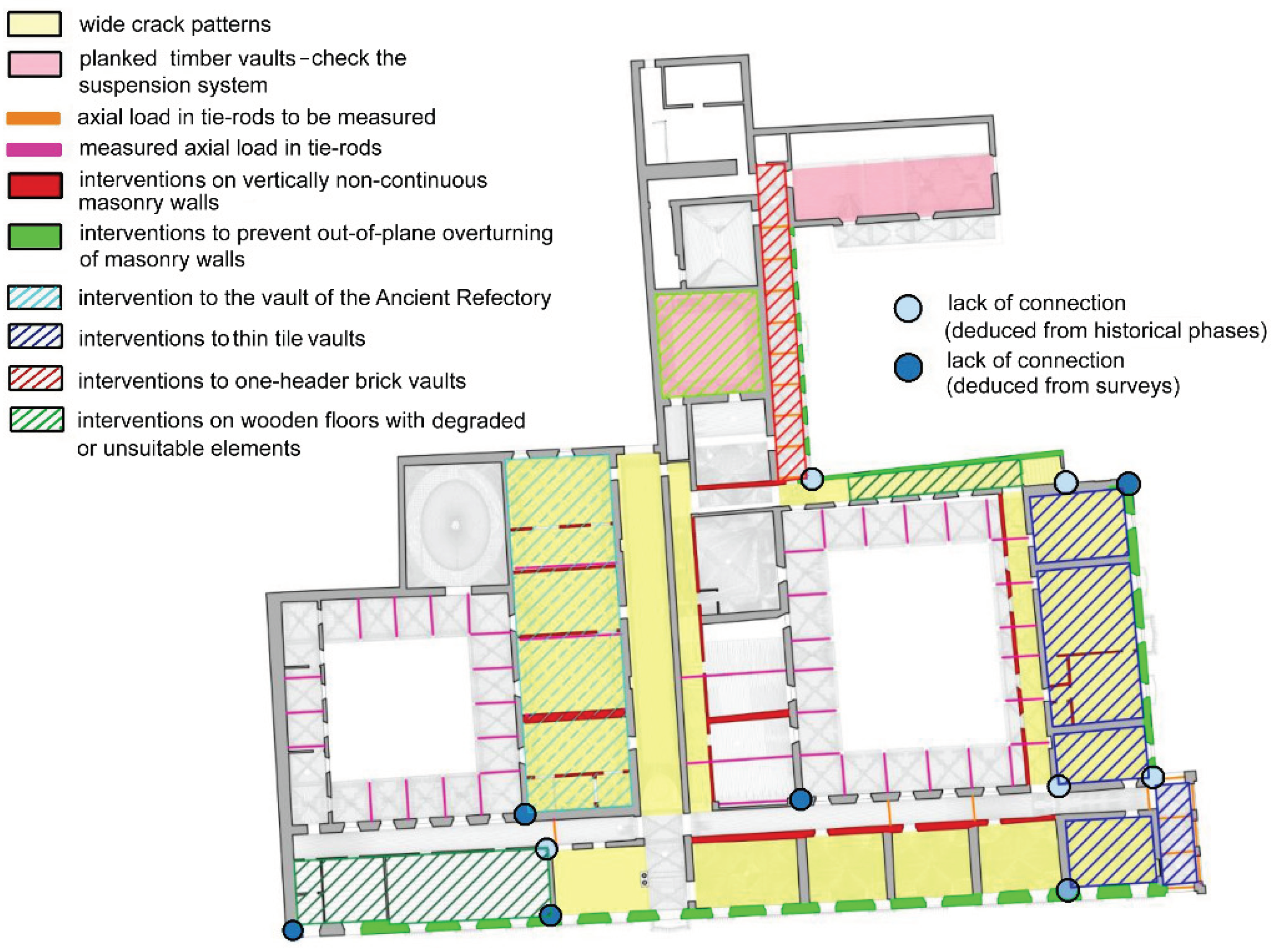
The database enables interactive three-dimensional visualization of structural elements and critical areas, facilitating the identification of those requiring further analysis or consolidation interventions. Based on this analysis, critical situations and areas needing further investigation are identified and visually represented on synthetic maps. This aids in depicting the current state and identifying the need for new tests for more in-depth structural analyses, forming the basis for the subsequent consolidation project. Figure 15 illustrates a sample summary map on the plan of the second floor, detailing major critical issues, new investigations to be carried out, and the macro-categories of intervention types proposed in this preliminary study.
4. Conclusions
The design of consolidation interventions for monumental buildings is a complex task that demands an understanding of structural behavior through a multidisciplinary knowledge process. This process initiates with geometric surveys, delves into the construction history, analyzes material structures, engages in numerical modeling, and ultimately culminates in the assessment of structural safety. In such cases, knowledge is not acquired in a single act following a predetermined method; rather, it is achieved through a series of successive approximations guided by progressive discoveries and subsequent evaluations. Given the significant artistic and historical value of the structures, this process necessitates collaborative efforts involving experts specialized in various aspects of the work. To facilitate this collaboration, systematically organizing the collected data is crucial, enabling integration and information sharing among different professionals. Additionally, the intricate shapes and articulated volumes of monumental buildings pose challenges in obtaining accurate geometric surveys, emphasizing the need for a model capable of rendering data readable and shareable, thereby enhancing knowledge and ensuring interoperability.
While the model presented in this study primarily focuses on the structural aspect of the building, it also has the capability to incorporate information about decorative elements, frescoes, architectural details, and the state of conservation of materials. This flexibility not only streamlines the design of new survey campaigns but also facilitates interventions that preserve the artistic value of the property. Furthermore, the integration of Virtual and Augmented Reality in managing information derived from the HBIM model opens additional opportunities for consolidating concentrated information within geolocated interactive interfaces. This enables immediate consultation and enhances the effectiveness of the model’s utilization. This application showcases the full potential of the HBIM system in the consolidation of existing monumental buildings, establishing it as a fundamental tool to guide the decision-making process in cultural heritage conservation projects.
Author Contributions
Conceptualization, A.D.; F.GA.; V.M. and M.M.; methodology, A.D.; F.GA.; V.M. and M.M.; software, F.GA.; V.M. and M.M.; validation, A.D.; F.G.; F.GA.; V.M. and M.M.; formal analysis, A.D.; F.GA.; M.M. and V.M.; investigation, A.D.; resources, A.D.; data curation, A.D.; F.G. and M.M.; writing—original draft preparation, A.D.; writing—review and editing, A.D.; F.G. and M.M.; visualization, A.D. and M.M.; supervision A.D. and F.G.; project administration, A.D.; All authors have read and agreed to the published version of the manuscript.
Funding
This research received no external funding.
Conflicts of Interest
The authors declare no conflicts of interest.
References
- Antón, D.; Medjdoub, B.; Shrahily, R.; Moyano, J. Accuracy evaluation of the semi-automatic 3D modeling for historical building information models. Int. J. Archit. Herit. 2018, 12, 790–805. [Google Scholar] [CrossRef]
- Remondino, F.; El-Hakim, S. Image-based 3d modelling: a review. Photogramm. Rec. 2006, 21, 269–291. [Google Scholar] [CrossRef]
- Potenziani, M.; Callieri, M.; Dellepiane, M.; Corsini, M.; Ponchio, F.; Scopigno, R. 3DHOP: 3D heritage online presenter. Comput. Graph. 2015, 52, 129–141. [Google Scholar] [CrossRef]
- Messaoudi, T.; Véron, P.; Halin, G.; De Luca, L. An ontological model for the reality-based 3d annotation of heritage building conservation state. J. Cult. Herit. 2018, 29, 100–112. [Google Scholar] [CrossRef]
- Apollonio, F.I.; Basilissi, V.; Callieri, M.; Dellepiane, M.; Gaiani, M.; Ponchio, F.; Rizzo, F.; Rubino, A.R.; Scopigno, R.; Sobra’, G. A 3d-centered information system for the documentation of a complex restoration intervention. J. Cult. Herit. 2018, 29, 89–99. [Google Scholar] [CrossRef]
- Azhar, S. Building information modeling (BIM): Trends, benefits, risks, and challenges for the AEC industry. Leadersh. Manag. Eng. 2011, 11, 241–252. [Google Scholar] [CrossRef]
- Dore, C.; Murphy, M. Integration of historic building information modeling (HBIM) and 3D GIS for recording and managing cultural heritage sites. In Proceedings of the 18th International Conference on Virtual Systems and Multimedia, IEEE, Milano, Italy, 2–5 September 2012. [Google Scholar] [CrossRef]
- Volk, R.; Stengel, J.; Schultmann, F. Building Information Modeling (BIM) for existing buildings - Literature review and future needs. Autom. Constr. 2014, 38, 109–127. [Google Scholar] [CrossRef]
- Yang, X.; Grussenmeyer, P.; Koehl, M.; Macher, H.; Murtiyoso, A.; Landes, T. Review of built heritage modelling: Integration of HBIM and other information techniques. J. Cult. Herit. 2020, 46, 350–360. [Google Scholar] [CrossRef]
- Celli, S.; Ottoni, F. An informative tool for the preservation of the wooden encircling tie rod of the dome of Santa Maria del Fiore, in Florence. In Proceedings of the joint international event 9th ARQUEOLÓGICA 2.0 & 3rd GEORES, Valencia, Spain, 26–28 April 2021. [Google Scholar] [CrossRef]
- Cardinali, V.; Ciuffreda, A.L.; Coli, M.; De Stefano, M.; Meli, F.; Tanganelli, M.; Trovatelli, F. An oriented H-BIM approach for the seismic assessment of cultural heritage buildings: Palazzo Vecchio in Florence. Buildings 2023, 13, 913. [Google Scholar] [CrossRef]
- Moyano, J.; León, J.; Nieto-Julián, J.E.; Bruno, S. Semantic interpretation of architectural and archaeological geometries: Point cloud segmentation for HBIM parameterisation. Autom. Constr. 2021, 130. [Google Scholar] [CrossRef]
- Monchetti, S.; Betti, M.; Borri, C.; Gerola, C.; Matta, C.; Francalanci, B. Insight on HBIM for conservation of cultural heritage: The Galleria dell’Accademia di Firenze. Heritage 2023, 6, 6949–6964. [Google Scholar] [CrossRef]
- Brumana, R.; Della Torre, S.; Oreni, D.; Previtali, M.; Cantini, L.; Barazzetti, L.; Franchi, A.; Banfi, F. HBIM challenge among the paradigm of complexity, tools and preservation: the Basilica di Collemaggio 8 years after the earthquake (L’Aquila). Int. Arch. Photogramm. Remote Sens. Spat. Inf. Sci. 2017, XLII-2/W5,2017, 97–104. [Google Scholar] [CrossRef]
- Bruno, N.; Roncella, R. Restoration oriented HBIM system for cultural heritage documentation: the case study of Parma Cathedral. Int. Arch. Photogramm. Remote Sens. Spatial Inf. Sci 2018, XLII-2, 171–178. [Google Scholar] [CrossRef]
- Della Torre, S.; Moioli, R.; Pili, A. Digital tools supporting conservation and management of built cultural heritage. In Innovative built heritage models; Koenraad van Balen, K., Aziliz, V.A., Eds.; CRC Press/Balkema—Taylor and Francis Group: Leiden, Netherlands, 2018; pp. 101–106. [Google Scholar] [CrossRef]
- Mora, R.; Sanchez-Aparicio, L.J.; Mate-Gonzalez, M.A.; García-Alvare, J.; Sanchez-Aparicio, M.; Gonzalez-Aguilera, D. An historical building information modelling approach for the preventive conservation of historical constructions: Application to the Historical Library of Salamanca. Autom. Constr. 2020, 121. [Google Scholar] [CrossRef]
- Santagati, C.; Papacharalambous, D.; Sanfilippo, G.; Bakirtzis, N.; Laurini, C.; Hermon, S. HBIM approach for the knowledge and documentation of the St. John the Theologian cathedral in Nicosia (Cyprus). J. Archaeol. Sci. Rep. 2021, 36. [Google Scholar] [CrossRef]
- Calì, A.; do Valle, Â.; de Moraes, P.D. Building Information Modeling and Structural Analysis in the Knowledge Path of a Historical Construction. In Structural Analysis of Historical Constructions; Aguilar, R., Torrealva, D., Moreira, S., Pando, M.A., Ramos, L.F., Eds.; RILEM Bookseries; Springer: Cham, Switzerland, 2019; Volume 18, pp. 2071–2079. [Google Scholar] [CrossRef]
- Crespi, P.; Franchi, A.; Ronca, P.; Giordano, N.; Scamardo, M.; Gusmeroli, G.; Schiantarelli, G. From BIM to FEM: The Analysis of an Historical Masonry Building. In WIT Transactions on the Built Environment; Wit Press: Bristol, UK, 2015; Volume 149, pp. 581–592. [Google Scholar] [CrossRef]
- De Luca, L.; Driscu, T.; Peyrols, E.; Labrosse, D.; Berthelot, M. A complete methodology for the virtual assembling of dismounted historic buildings. Int J Interact Des Manuf. 2014, 8, 265–276. [Google Scholar] [CrossRef]
- Dore, C.; Murphy, M.; McCarthy, S.; Brechin, F.; Casidy, C.; Dirix, E. Structural simulations and conservation analysis–historic building information model (HBIM). Int. Arch. Photogramm. Rem. Sens. Spat. Inf. Sci. 2015, XL-5/W4, 351–357. [Google Scholar] [CrossRef]
- Mol, A.; Cabaleiro, M.; Sousa, H.S.; Branco, J.M. HBIM for storing life-cycle data regarding decay and damage in existing timber structures. Autom. Constr. 2020, 117. [Google Scholar] [CrossRef]
- Bruno, S.; De Fino, M.; Fatiguso, F. Historic building information modelling: performance assessment for diagnosis-aided information modelling and management. Autom. Constr. 2018, 86, 256–276. [Google Scholar] [CrossRef]
- Bouzas, Ó.; Cabaleiro, M.; Conde, B.; Cruz, Y.; Riveiro, B. Structural health control of historical steel structures using HBIM. Autom. Constr. 2022, 140. [Google Scholar] [CrossRef]
- Barazzetti, L.; Banfi, F.; Brumana, R.; Oreni, D.; Previtali, M.; Roncoroni, F. HBIM and augmented information: Towards a wider user community of image and range- based reconstructions. Int. Arch. Photogramm. Rem. Sens. Spat. Inf. Sci. 2015, XL-5/W7, 35–42. [Google Scholar] [CrossRef]
- Conti, A.; Fiorini, L.; Massaro, R.; Santoni, C.; Tucci, G. HBIM for the preservation of a historic infrastructure: the Carlo III bridge of the Carolino aqueduct. Appl. Geomat. 2022, 14, 41–51. [Google Scholar] [CrossRef]
- Garcìa-Valldecabres, J.L.; Liu, J.; Willkens, D.S.; Escudero, P.A.; Lòpez-Gonzalez, C.; Cortès Meseguer, L.; Orozco Carpio, P. Development of a virtual itinerary with HBIM and GIS. Int. Arch. Photogramm. Rem. Sens. Spat. Inf. Sci. 2023, 48, 645–652. [Google Scholar] [CrossRef]
- Lovell, L.J.; Davies, R.J.; Hunt, D.V. The application of historic building information modeling (HBIM) to cultural heritage: A review. Heritage 2023, 6, 6691–6717. [Google Scholar] [CrossRef]
- Manghi, A. La Certosa di Pisa: Storia (1366-1866) e Descrizione; Tip, Ed.; Mariotti: Pisa, Italia, 1911. [Google Scholar]
- Piombanti, G. La Certosa di Pisa e dell’Isola di Gorgona: Con Notizie Inedite e la Descrizione Della Prima Come Esiste Presentemente/pel Sacerdote Giuseppe Piombanti; Tip. G. Fabbreschi e C.: Livorno, Italia, 1884. [Google Scholar]
- Giusti, M.A.; Lazzarini, M.T. La Certosa di Pisa a Calci; Pacini: Pisa, Italia, 2003. [Google Scholar]
- Borri, A.; Corradi, M.; Castori, G.; De Maria, A. A method for the analysis and classification of historic masonry. Bull. Earth. Eng. 2015, 13, 2647–2665. [Google Scholar] [CrossRef]
- Resta, C.; Chellini, G.; De Falco, A. Dynamic Assessment of Axial Load in Tie-Rods by Means of Acoustic Measurements. Buildings 2020, 10, 23. [Google Scholar] [CrossRef]
- Ideate–BIMLink. Available online: https://ideatesoftware.com/support/help/ideate-bimlink(accessed on March 2020).
- NTC 2018 (DM del Ministero delle Infrastrutture e dei Trasporti del 17/01/2018) (2018). Aggiornamento delle “Norme Tecniche per le Costruzioni”. G.U. Serie Generale n.42 del 20.02.2018 - S.O. n. 8.
- Autodesk, Dynamo BIM. 2016. Available online: https://dynamobim.org/ (accessed on 20 March 2020).
- Bartolini, G.; Giuliani, F.; De Falco, A. Proof of Concept for Methodological Framework Including Point Clouds in the Non-Destructive Diagnosis of Historical Masonry Structures. Int. J. Archit. Herit. 2023, 1–24. [Google Scholar] [CrossRef]
Figure 1.
The Certosa di Pisa: aerial view.
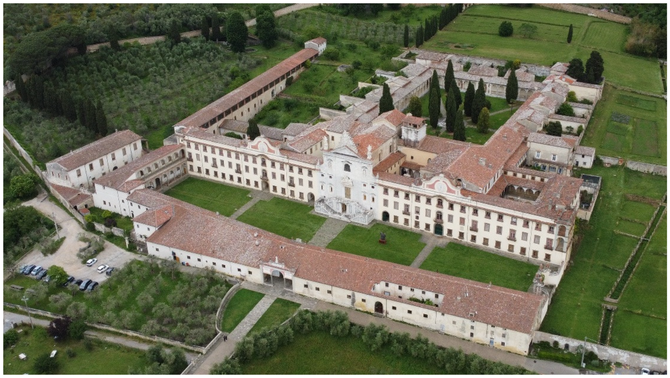
Figure 2.
Intended uses in the XVIII century layout of the Certosa, with indication of the study area.
Figure 2.
Intended uses in the XVIII century layout of the Certosa, with indication of the study area.
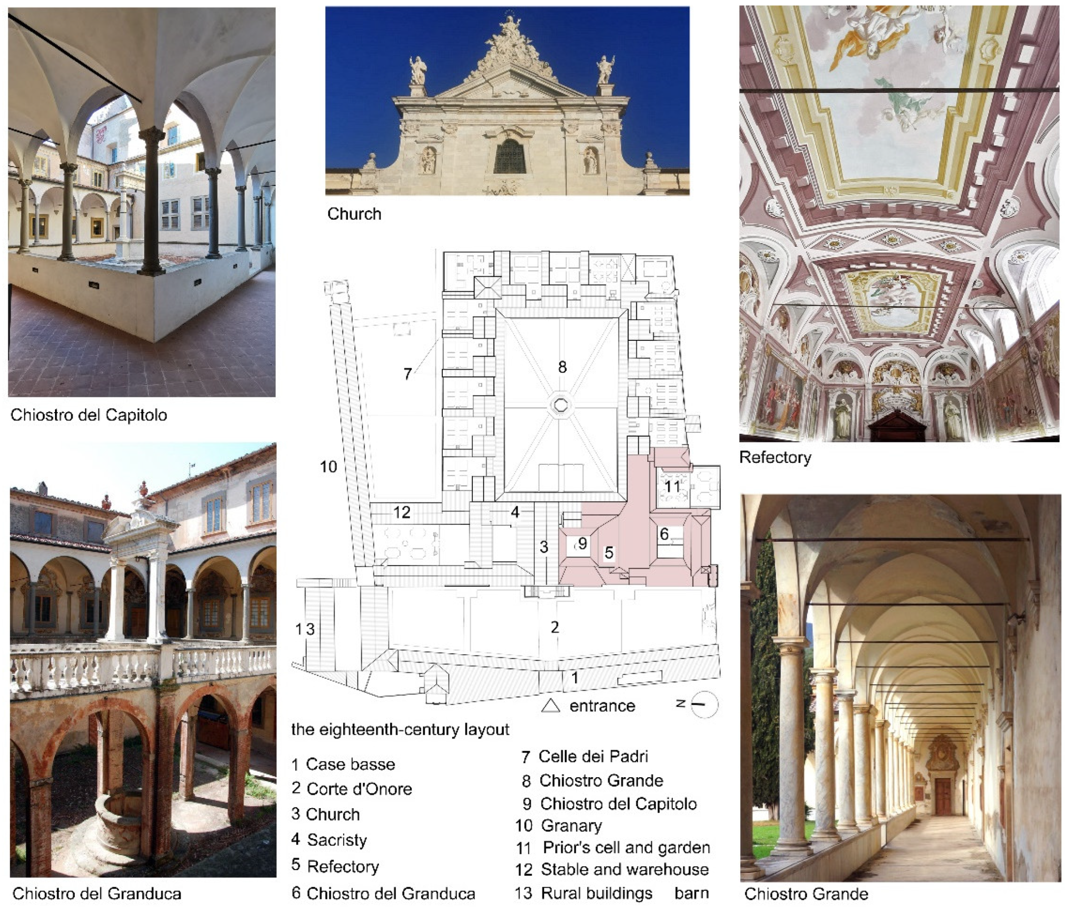
Figure 3.
Phases of creating the three-dimensional model starting from the point cloud.
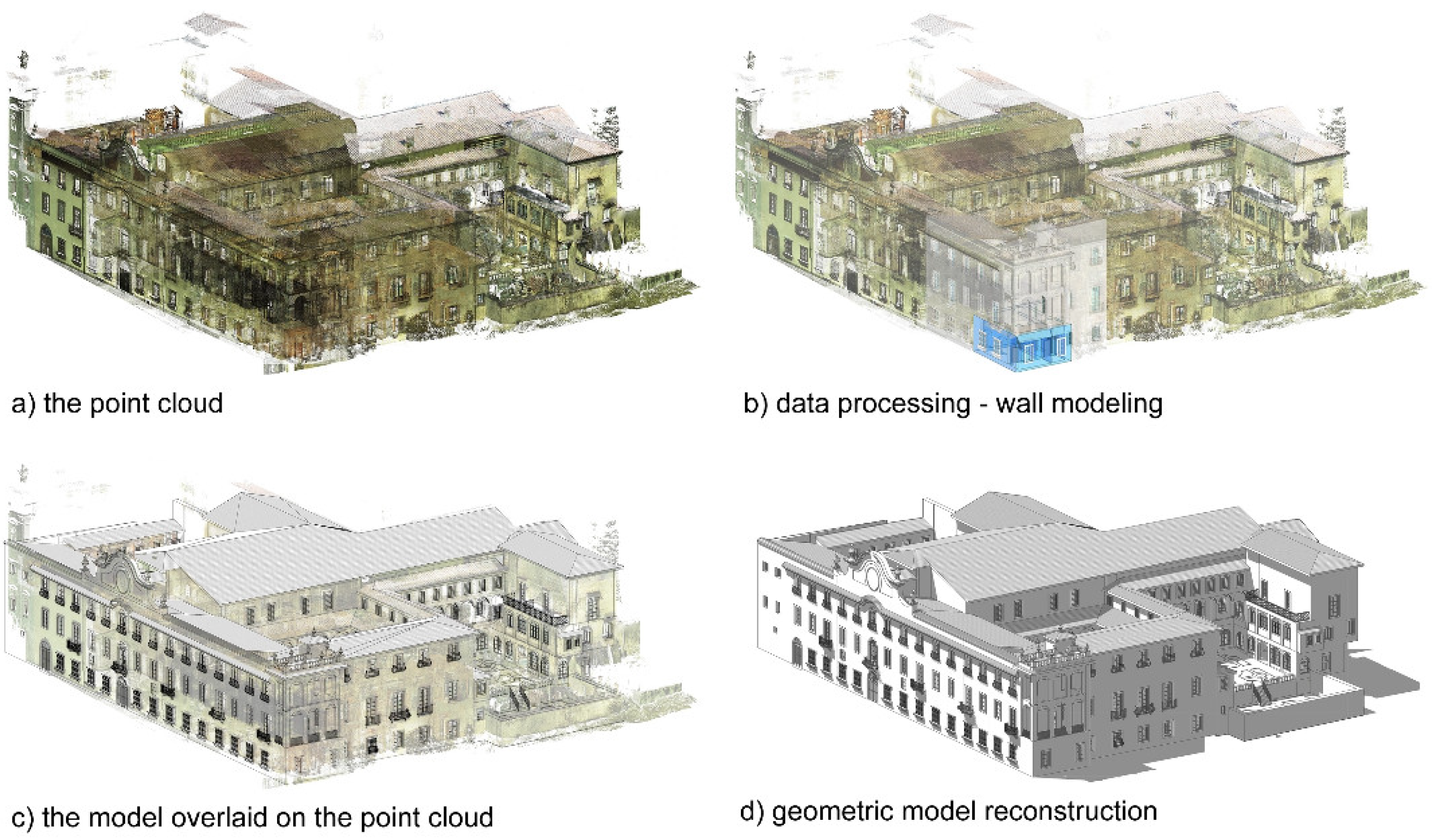
Figure 4.
The process of modeling the vaults: (a) generating curves; (b) creating surface mesh; (c) placing the mesh within the geometrical structures.
Figure 4.
The process of modeling the vaults: (a) generating curves; (b) creating surface mesh; (c) placing the mesh within the geometrical structures.
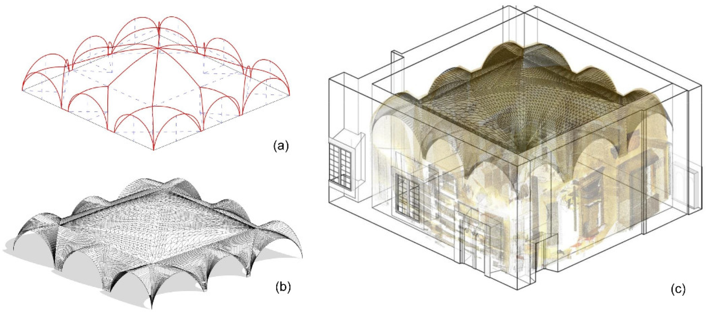
Figure 5.
The process of modeling the vaults.
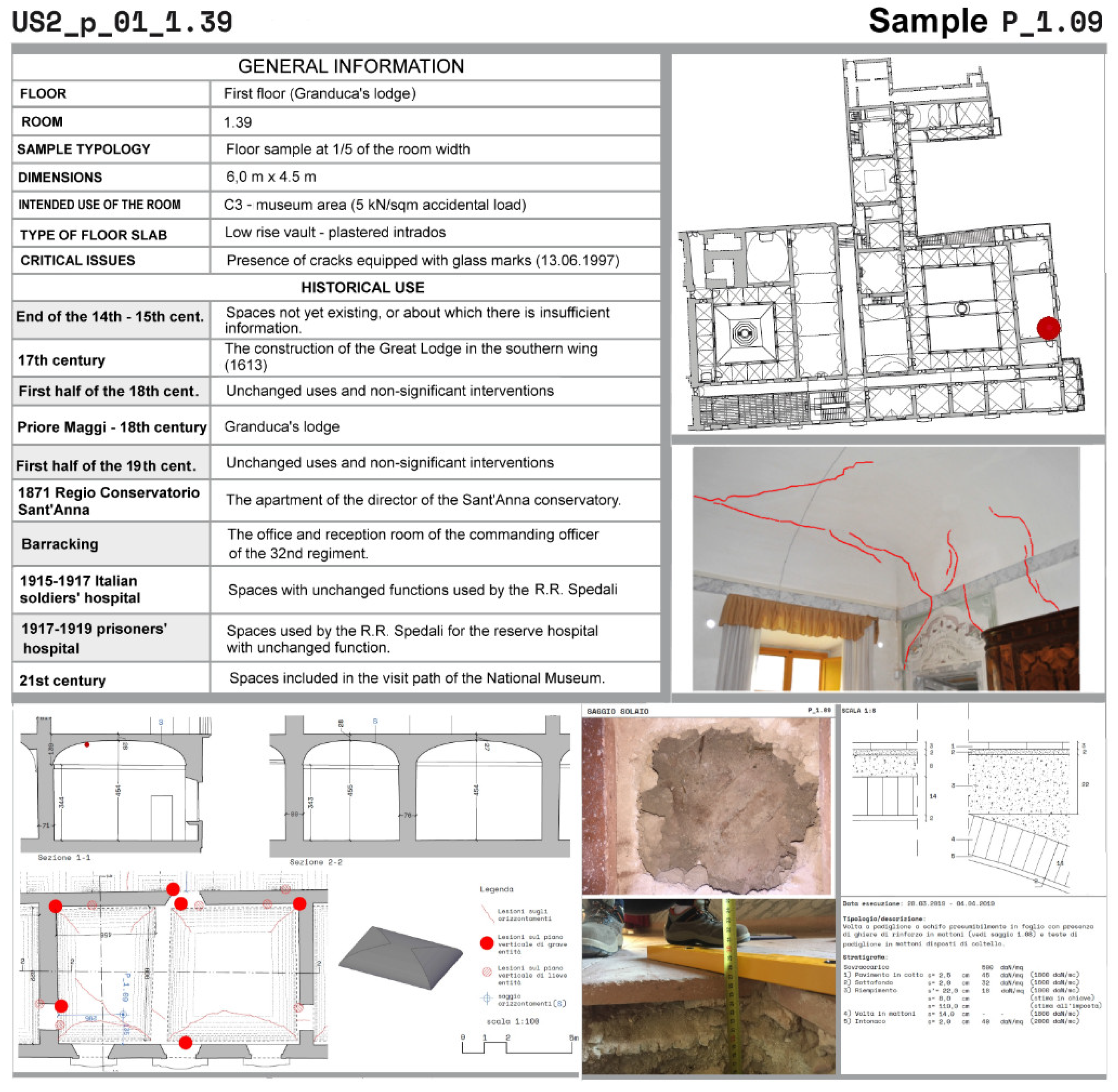
Figure 6.
Logical organization of the database.
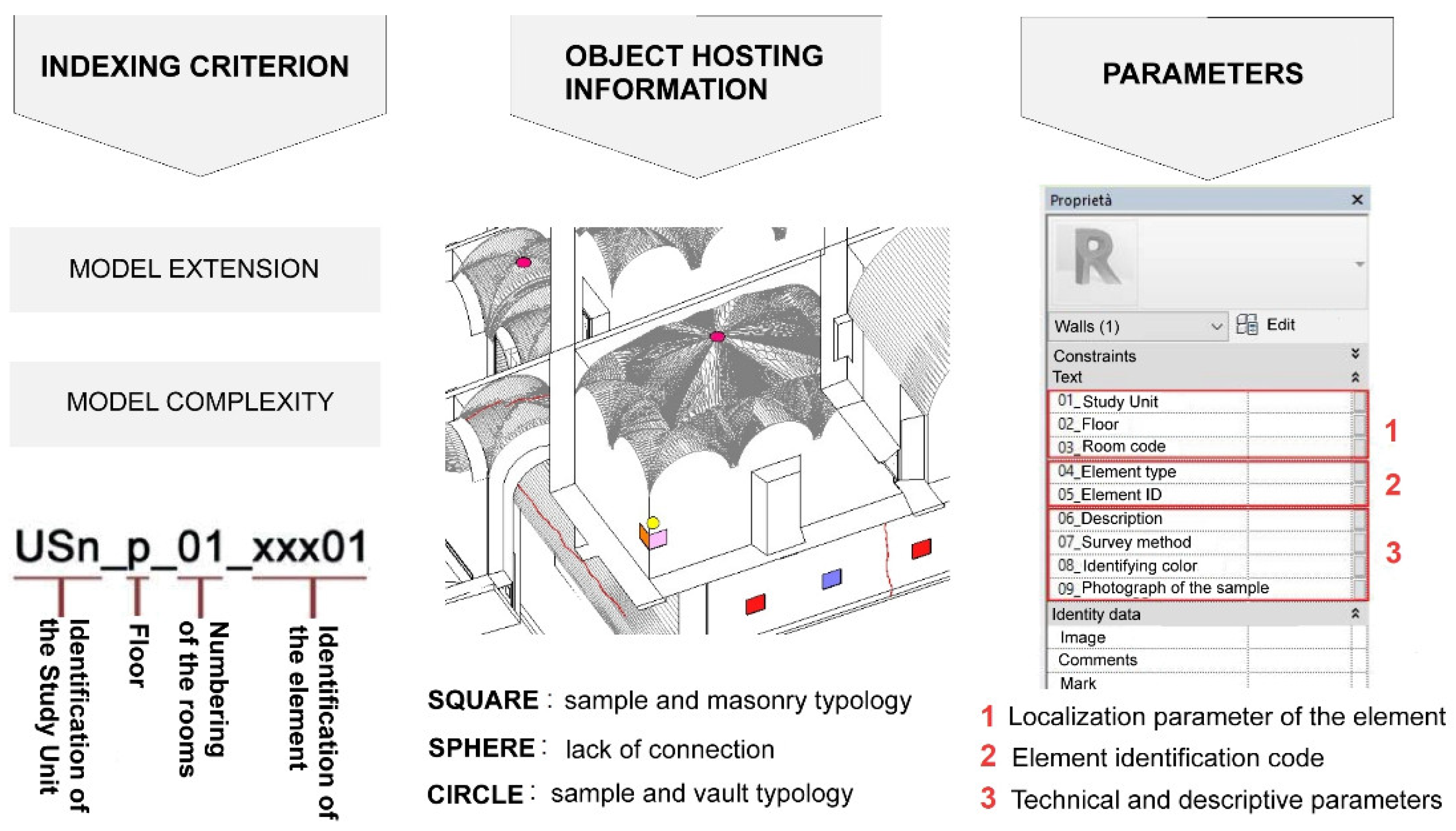
Figure 7.
Views of the horizontal structures of the attic floor and the first level of the study area, with relative forms.
Figure 7.
Views of the horizontal structures of the attic floor and the first level of the study area, with relative forms.
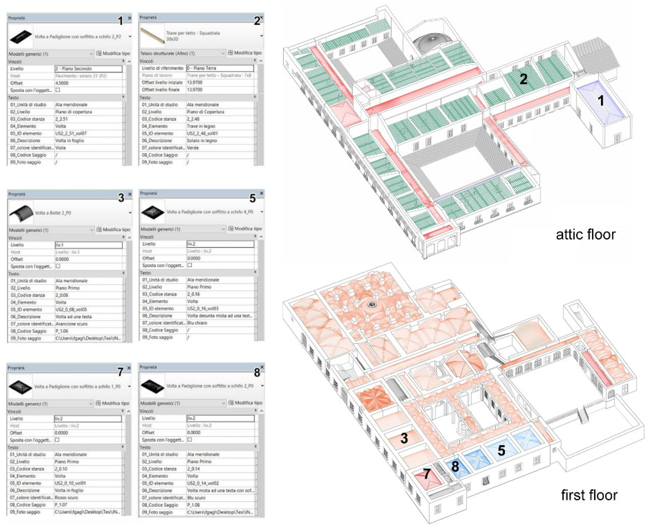
Figure 8.
The first two construction phases of the Certosa di Pisa.
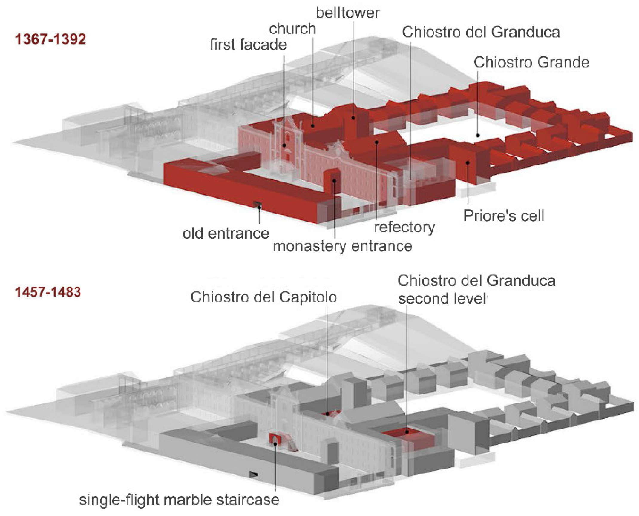
Figure 9.
North-south section of the model with the position of the on-site tests.
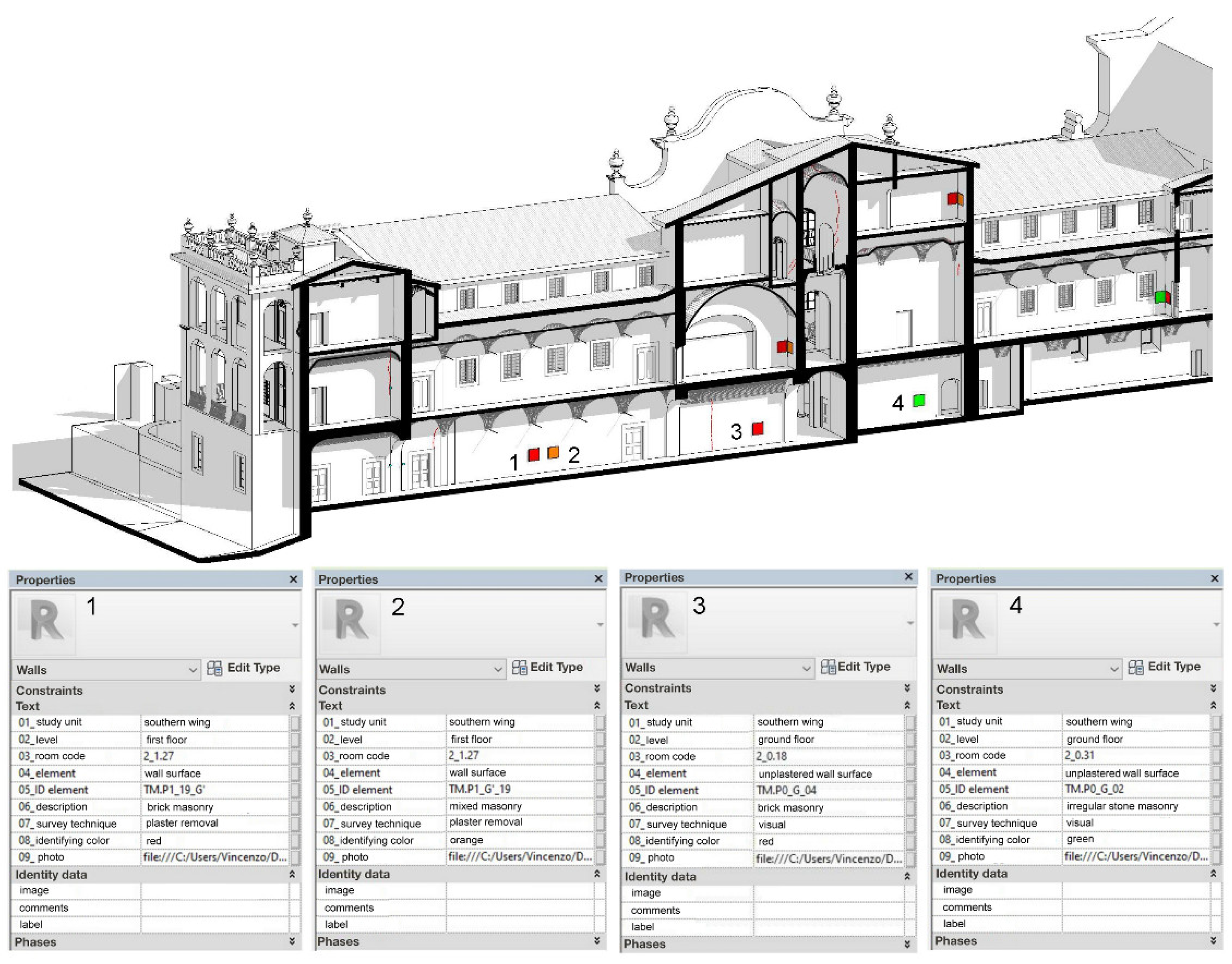
Figure 10.
Screenshot of a virtual tour on the Granduca Cloister.
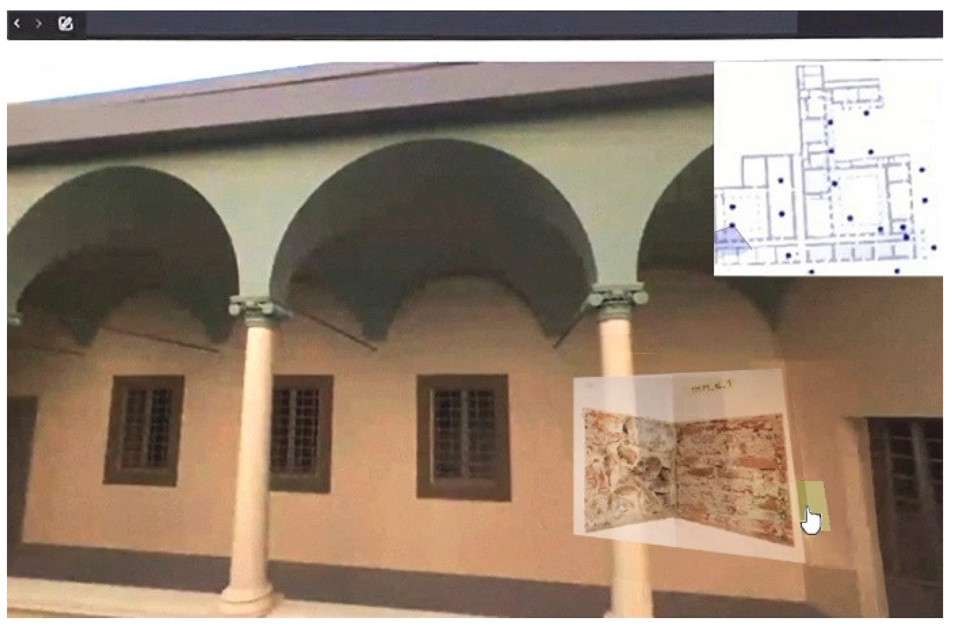
Figure 11.
Map of wall macro-categories - first floor plan of the study area.
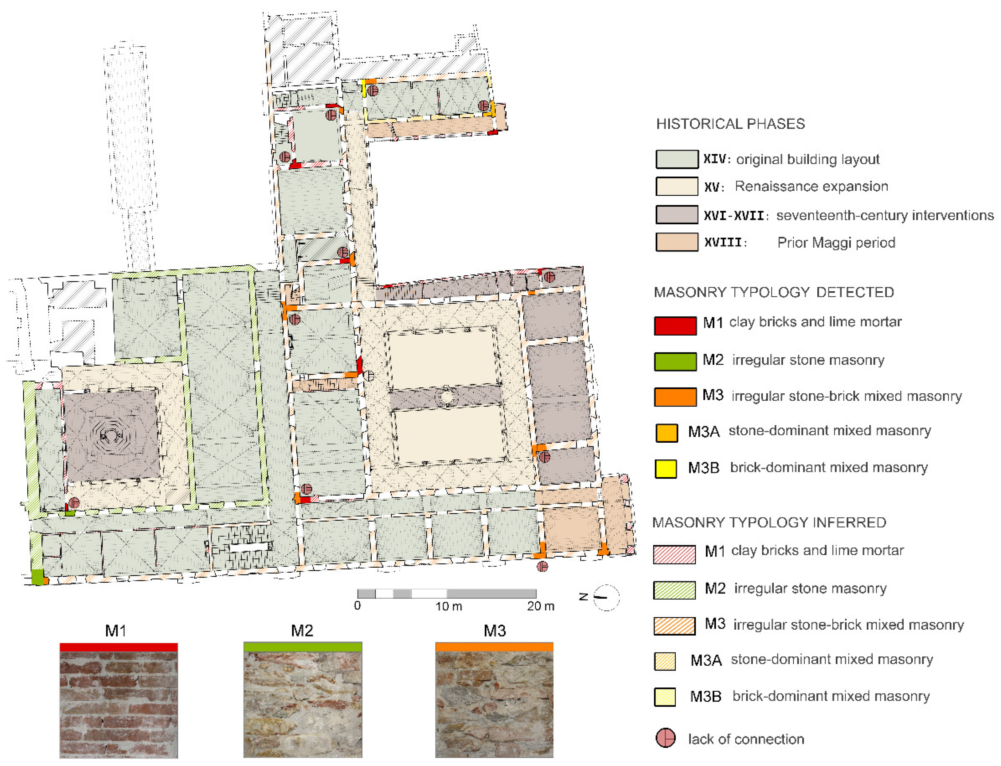
Figure 12.
Perspective images exportable from the HBIM: a) Granduca Cloister b) Ancient Refectory.
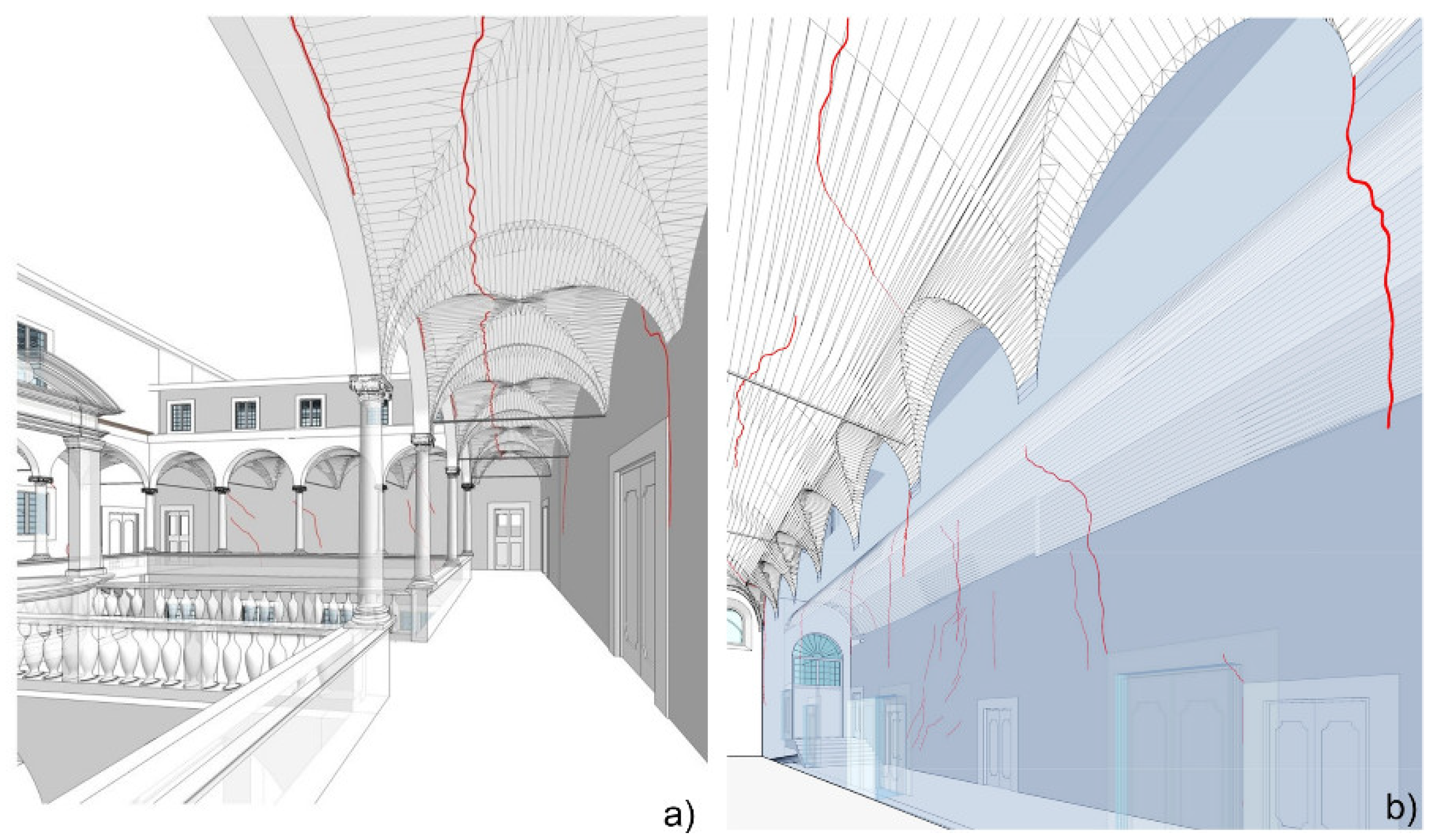
Figure 13.
Visualization of the results of the static assessment in HBIM environment.
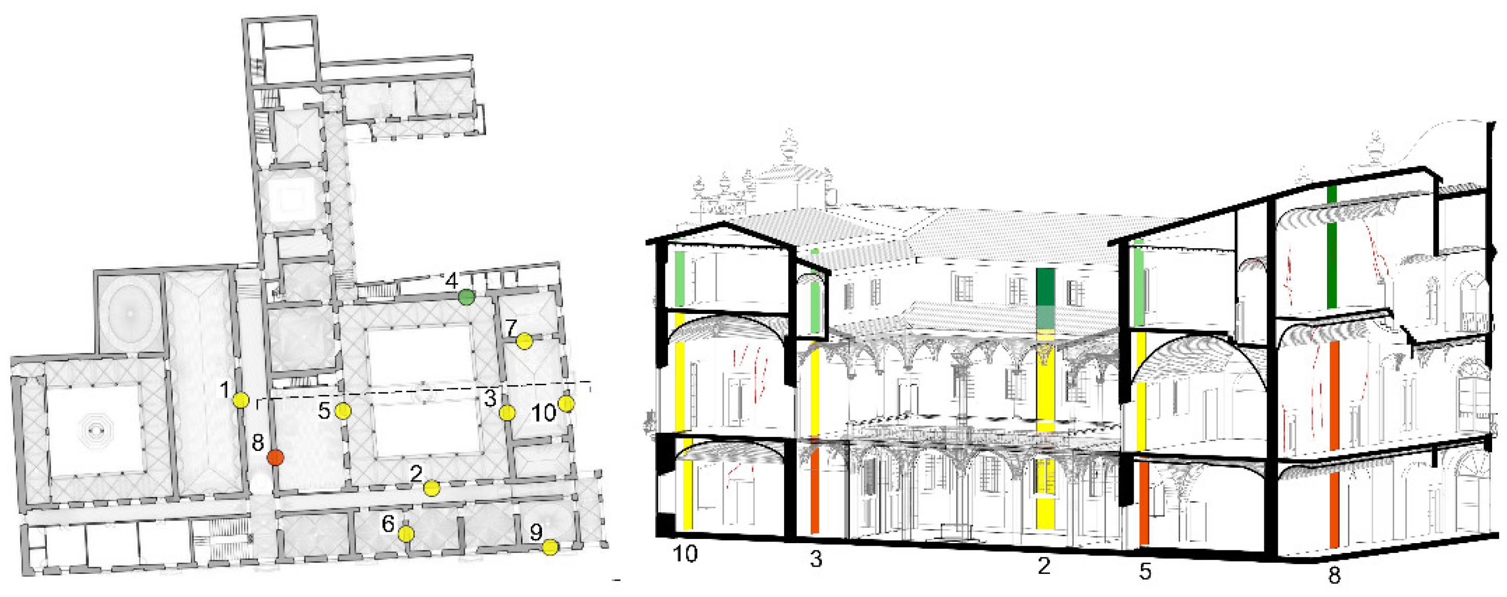
Figure 14.
Some seismic collapse mechanisms identified: a) decorative elements on the upper part of the main façade; b) loggia in the southwest corner; c) Prior’s loggia.
Figure 14.
Some seismic collapse mechanisms identified: a) decorative elements on the upper part of the main façade; b) loggia in the southwest corner; c) Prior’s loggia.
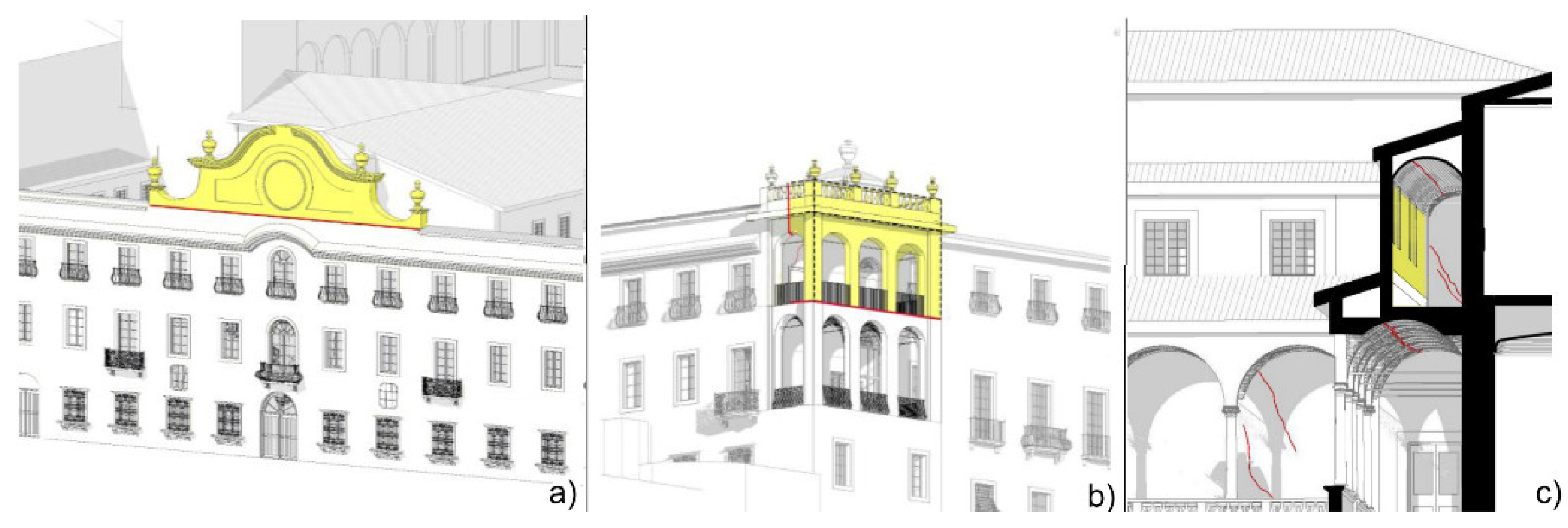
Figure 15.
Plan of the second floor of the study area: the map summarizes the detected critical issues, the intervention categories, and the new knowledge needs.
Figure 15.
Plan of the second floor of the study area: the map summarizes the detected critical issues, the intervention categories, and the new knowledge needs.
Disclaimer/Publisher’s Note: The statements, opinions and data contained in all publications are solely those of the individual author(s) and contributor(s) and not of MDPI and/or the editor(s). MDPI and/or the editor(s) disclaim responsibility for any injury to people or property resulting from any ideas, methods, instructions or products referred to in the content. |
© 2024 by the authors. Licensee MDPI, Basel, Switzerland. This article is an open access article distributed under the terms and conditions of the Creative Commons Attribution (CC BY) license (http://creativecommons.org/licenses/by/4.0/).
Copyright: This open access article is published under a Creative Commons CC BY 4.0 license, which permit the free download, distribution, and reuse, provided that the author and preprint are cited in any reuse.
Submitted:
18 February 2024
Posted:
19 February 2024
You are already at the latest version
Alerts
A peer-reviewed article of this preprint also exists.
This version is not peer-reviewed
Submitted:
18 February 2024
Posted:
19 February 2024
You are already at the latest version
Alerts
Abstract
In the conservation of monumental heritage, the collection and utilization of information are of primary importance. The Heritage Building Information Modeling (HBIM) procedure harnesses the potential of three-dimensional models, offering significant advantages in accessing documentation, interoperability, multidimensionality of intervention design, cost evaluation and maintenance management. Attention here is focused on the Certosa di Pisa, a large historical complex built in the 14th century as a monastery of the Carthusian order, currently in a state of deterioration and in need of restoration and re-functionalization. The multifaceted nature of this monumental complex, with its intricate interplay of architectural elements spanning different historical periods and featuring diverse techniques, poses a significant challenge for structural safety assessment. This case study presents an opportunity to explore an HBIM approach to streamline the diagnostic process and facilitate the intervention design phase. The goal is achieved by utilizing an accurate 3D model enriched with data from multiple sources and automating certain operations for structural assessment. The usefulness of the HBIM methodology is highlighted as a valuable tool in the realm of Cultural Heritage structures for both technicians and scholars alike.
Keywords:
Subject: Engineering - Architecture, Building and Construction
1. Introduction
In recent decades, significant progress has been made in the field of two- and three-dimensional digital representation, enabling the acquisition of precise models for documenting existing architectural heritage. 3D models generation can be achieved through various techniques, including solid modeling, which can be handled directly or parametrically controlled, as well as meshes created through triangulation of point cloud coordinates [1]. These different techniques are typically used in combination, as none of them individually can guarantee high levels of accuracy, automation, realism, and model manipulation capabilities, while ensuring cost and time efficiency for surveying and processing [2]. There are many examples showing the application of these techniques in the field of cultural heritage, facilitating the high-resolution reproduction of historical structures and objects, as well as the development of integrated interfaces for documentation and presentation of multimedia content [3].
Contemporary systems not only allow representation but also the possibility to enrich 3D models with additional information, thus enabling the creation of ontological models [4,5]. However, when it comes to historic buildings, more research efforts are needed to effectively manage the numerous and diverse information regarding the construction history, transformations, materials, and state of conservation. A potential solution to address these challenges is provided by Building Information Modeling (BIM) systems. BIM does not refer to a specific object, namely the 3D model, or software, but rather denotes a collaborative process for producing and managing structured digital information. The goal is to create a shared database that goes beyond traditional representations, constituting a semantically enriched model that centralizes the collection and exchange of information between stakeholders throughout the entire life cycle of construction [6].
The application of the BIM process in the context of heritage buildings is known as Heritage or Historical BIM (HBIM) [7]. HBIM involves modeling building elements as parametric objects in a database library and processing large amounts of data from various sources. While BIM is well established in the new construction sector, its use in historic building contexts is relatively new, but progressively expanding due to its significant advantages, such as quick access to documentation, interoperability in the analysis, multidimensionality in the design phase, ease of cost assessment at each stage and improved management of maintenance and interventions [8,9]. In fact, having an informed digital model of the building enables experts to have a comprehensive view that is the starting point to identify structural and conservation deficiencies and to simulate different scenarios of intervention.
Unlike the BIM process, which leverages the combination of elements chosen from a library usually already possessing information, HBIM implies the creation of a model of the construction, to which data is subsequently associated. The HBIM process primarily involves a reverse-engineering operation that transforms survey data into a digital representation of the structure. This process generally consists of three stages: information acquisition, which entails surveying the geometry and relevant features; information processing, which involves creating the actual proprietary model; and data fusion, which incorporates additional information into the model. During this final stage, the potential of the HBIM process for information management in historic architectures becomes evident. The model can systematically incorporate both quantitative and qualitative data, allowing for easy extraction when needed. Furthermore, the ability to accommodate diverse data types and sources promotes collaboration among professionals working on the same asset in different capacities. A comprehensive and well-organized catalog of gathered data can play a vital role in different aspects of building restoration and management, offering valuable assistance, especially during operational phases [10]. This information often spans various disciplinary domains, and correlating diverse data sets can streamline the generation of analyses. Furthermore, the potential exists to employ a dynamic model that remains continually updatable and expandable, fostering collaboration among professionals in different roles [11]. The utilization of semantically enriched 3D elements enables navigation through the model accompanied by data such as photographs, links, descriptions, and 2D drawings. Additionally, querying the model facilitates the creation of thematic maps [12]. This comprehensive approach serves as an effective solution for synthesizing, organizing, and storing information, which is essential for knowledge acquisition and decision-making in conservation projects. In this interdisciplinary setting, HBIM methodologies emerge as a promising and efficient tool for the preservation of historical assets [13]. They provide an effective approach to understanding, preserving, and restoring historical architecture, with the potential for centralized management of all documentation. In recent years, some experiments have been conducted in this regard [14,15,16,17]. Works have demonstrated the advantages of applying the method to complex and multilayered historical buildings, highlighting the transformations caused by restoration work. In [18], an application for studying the architectural history and conservation status of the Cathedral of St. John the Theologian in Nicosia, Cyprus, is presented, while [15] focuses on managing non-geometric information in Historic Building Information Modeling (HBIM) and translating the traditional conservation procedure in the interesting case of the Cathedral of Parma.
The HBIM method has recently been used for preventive conservation [19], restoration project development, and structural analysis [19,20] of ancient constructions of various types and materials. Among these, we can mention its application to the ancient Library of Salamanca (Spain) for preventive conservation [19], the cloister of Saint-Guilhem-le-Désert (France) [21], and the Four Courts Palace (Ireland) [22], respectively, for surveying, representation, and sharing of architectural heritage.
In [23], HBIM is used for collecting and organizing data related to the degradation of existing wooden structures, and, more generally, in [24] the main literature contributions using HBIM for managing data from diagnostic activities and monitoring of existing structures and infrastructures are reported. Similarly, in [25], HBIM is applied for the control and monitoring of the structural safety of the ancient metal bridge O Barqueiro in Galicia. Finally, in [26] and [27], the digital representation of the built environment and the management of documentation are addressed, respectively, aiming for better utilization of BIM projects through the use of portable tools and the creation of as-built projects for structures and infrastructures.
The capabilities of integrating HBIM with GIS have also been explored [9], leveraging the strengths of this powerful tool that serves various purposes in geographic and urban contexts, including risk control, planning, analysis, and visualization [28]. For a comprehensive overview of the current state of HBIM implementation and research trends, [29] provides a valuable review of the existing literature.
At present, numerous BIM platforms are employed by professionals for tasks such as modelling, visualizing, assembling, and managing architectural heritage knowledge. However, despite the increasing applications of BIM technologies in HBIM workflows, the discipline still lacks a standardized approach to HBIM implementation. This limitation restricts the application of BIM technology and hinders the realization of associated benefits in the research and preservation of historical structures.
The present work is part of a preliminary study carried out by a multidisciplinary group of experts of the University of Pisa to evaluate the structural safety of the Certosa di Pisa, a monastery of the Carthusian order established in the XIV century. The monumental complex, currently in a state of severe deterioration, needs restoration and re-functionalization. This study, focused on the south-western section of the Certosa, offers the opportunity to explore the application of the Building Information Modeling (BIM) methodology. Emphasis is placed on the structural aspects, which require specific strategies to automate some operations for the safety assessment of the historic and artistic structures. The objective of this work is to find a methodology for synthesizing and organizing information, to identify critical issues, plan the necessary interventions and evaluate their technical feasibility. A procedural framework is established for carrying out the structural analyses through an operational process that can be easily extended to the entire Monumental Complex. The article outlines the fundamental phases of the realization of the model and highlights the characteristics that make it a valid tool in the knowledge acquisition phase and in the planning of consolidation and restoration interventions.
2. Materials and Methods
2.1. The Certosa di Pisa
The Certosa di Pisa is a large historical complex located in the Municipality of Calci, a small town near Pisa. In the Val Graziosa, on the slopes of Monte Pisano amidst olive and cypress trees (Figure 1a), the Certosa was originally established in 1366 as a monastery of the Carthusian order of San Bruno [30]. It underwent significant enlargement between the XVII and XVIII centuries, resulting in its current late Baroque appearance (Figure 1). Currently, the site is partially used by the University of Pisa, managing the Museum of Natural History, and partially by the Ministry of Culture, overseeing the National Museum of the Monumental Charterhouse of Calci.
The Complex comprises multiple buildings, each serving specific functions (Figure 2). The western façade houses a building known as Case Basse, which spans approximately 150 meters and consists of two above-ground stories. This structure hosted various services for the Charterhouse, including the pharmacy, San Sebastiano chapel, and the parlor, which were accessible to residents as well. In front of the Case Basse there is the cloistered monastery proper, an imposing three-story edifice with the main façade facing west, separated from the Case Basse by a large green area called Corte d’Onore. At the center of the complex there is the church, originally built for the exclusive use of the monks. The church features a grand double-ramp staircase, a magnificent façade covered in white marble and decorated on the tympanum by a statue of the Assumption surrounded by angels (Figure 2).
Next to the church there are the sacristy, the chapels, the Chapter House, the lodgings for the lay brothers, and the buildings dedicated to rural activities. At the rear of the church there is the Great Cloister (Chiostro Grande), lined with the fifteen cells of the monks (Celle dei Padri), as well as the worship rooms, the Refectory, and the Chapter House. Other cloisters in the south-western portion are the Capitolo Cloister (Chiostro del Capitolo), overlooked by the chapel, and the Granduca (or Foresteria) Cloister (Chiostro del Granduca o della Foresteria), surrounded by the dwellings of the lay brothers.
By around 1390, essential spaces for Carthusian life had been completed, including the church with several chapels, the chapter house, a portion of the monks’ cells in the Great Cloister, the cells for the lay brothers, the refectory, and the kitchens [31,32]. In the second half of the 14th century, there was a primarily decorative activity, which came to a halt at the end of the 15th century, when the monastery experienced a period of economic hardship due to renewed tensions between Pisa and Florence. In the early 17th century, a significant renovation phase ensued, involving modifications and expansions of the rooms around the Granduca Cloister, along with the addition of new cells in the Great Cloister. In this period, alterations were also made to the Case Basse, and a new entrance was created in line with the church.
The final significant construction phase that shaped the current appearance of the Certosa di Pisa took place in 1764. In this period, the Corte d’Onore was nearly doubled in size, a bell tower was erected (which remained unfinished) and a large granary was built in the northern area of the Complex. However, starting from 1809, the Carthusian community had to face increasingly unfavorable political and economic circumstances, which led to a deep crisis and the near cessation of building activities. Following the suppression of religious orders by Napoleon Bonaparte, the Certosa lost all its properties, and the monks were compelled to leave.
After the restoration of ecclesiastical communities by Leopold II, the Carthusians returned as secular monks, and some restoration work was carried out. However, after the definitive suppression of religious orders upon the establishment of the Kingdom of Italy, all assets were transferred to the State Property. Fortunately, the law recognized the immense value of the Monastic Complex, declaring it of monumental importance. This fact contributed to the preservation of the Certosa di Pisa from alterations by private individuals, unlike what happened to other Italian Carthusian monasteries.
In 1869, a portion of the Southern area was entrusted to the Royal Conservatory of Sant’Anna, resulting in some transformations that were later reversed. From 1871, for almost a century, the monks were allowed to remain in the monastery but were compelled to share the space with other institutions. In 1888, the Carthusian Monastery temporarily served as an artillery unit, and in 1915, the non-monastic portion was used as a barracks, followed in 1916 by a reserve hospital and from 1917 to 1919 by a hospital for prisoners of war of the Austro-Hungarian army. In 1972, the last monks definitively left the Carthusian hermitage, which in 1979 was partially assigned to the University of Pisa and transformed into a museum. Currently, the Complex is managed jointly by the University of Pisa, which occupies most of the rooms in the northern section as the Museum of Natural History, and by the Ministry of Culture, with the National Museum of the Monumental Certosa di Calci, which occupies most of the rooms in the southern section. The Celle dei Padri are managed by both administrations: the northern cells are under the supervision of the Ministry of Culture and the southern ones under the University of Pisa. The ground floor and the second floors of the monastery are mainly used as exhibition spaces accessible to the public, with some areas intended for storage and warehouses. Additionally, certain rooms on the second floor serve as offices for university staff, and there are accommodations available for staff members in the Case Basse.
At present, the buildings of the Certosa di Pisa are generally in a state of decay, with considerable deterioration in the wooden floors, roofs, and, in some cases, in the masonry materials. This deterioration is often caused by factors such as water infiltration from roofs or rising damp from the ground, both capable of significantly compromising the integrity of the masonry. Furthermore, the fragmentation of governance, stemming from the existence of two separate administrations, is having a detrimental impact on resolving these critical issues, ultimately exacerbating deterioration.
The University of Pisa recently acknowledged the necessity for restoring and re-functionalizing the entire Complex. They initiated an extensive study, engaging various expertise within the university. The south-western area was selected as a case study for a pilot project, focusing on the cenobitic region, the Granduca Apartments, the Granduca Cloister, and the Capitolo Cloister.
2.2. Investigation on the South-West Portion of the Certosa di Pisa
Investigating the structures of the monumental Complex required significant effort due to their large dimensions, numerous construction phases and transformations with various uses over time, as well as extensive decorative elements covering most surfaces. In 2018, a survey campaign was conducted, employing both manual techniques and laser scanners. Additionally, a series of on-site tests were planned and executed to identify the construction elements and their interconnections accurately. To achieve this, specific forms were prepared containing the test list, indicating the position and purpose of each test, describing the room where the test would occur, and recording the presence of decorative elements within it. The forms also included details about equipment, execution methods, estimated costs, and priority levels for each investigation. The survey aimed to characterize the main masonry typologies in the area, utilizing the Index of Masonry Quality (IQM) method [33] to estimate strength values for each masonry type. The materials identified include bricks for the vaults and walls, sandstone for the columns of the cloisters, and locally sourced stone, primarily quartzite from the nearby Monti Pisani, used for the general masonry. Three main masonry macro-categories were identified: stone masonry with a chaotic texture, mixed stone and brick masonry with chaotic texture, and brick masonry with lime mortar. Due to the limited number of tests, mapping the masonry was also done by analogy, where the identified masonry typology was extended to areas believed to belong to the same construction phase. A similar approach was also taken for vault types, as investigating their internal structure was often impractical. Additionally, connection deficiencies between wall panels at the interface of different construction phases were hypothesized and later verified through structural tests. Extensive explorations of the roofs were conducted, with attempts made to assess the physical and mechanical properties of the timber whenever feasible. Concurrently, load values were measured in approximately forty metal tie rods. This provided an opportunity to employ innovative techniques using acoustic measurement [34]. The investigation included analyzing crack and deformation patterns, creating a three-dimensional geometric model for exploration, and assessing material types and their continuity. These efforts greatly facilitated the identification of underlying causes of instability symptoms, structural deficiencies, potential active mechanisms, and primary vulnerabilities.
Based on these observations, intervention proposals were formulated, and additional structural tests were recommended to evaluate their feasibility. In this context, the HBIM played a crucial role by synthesizing all collected data and enabling its visualization on the three-dimensional model. The HBIM model has proven invaluable for synthesizing information and guiding decision-making regarding intervention strategies and further investigations.
2.3. Creation of the HBIM Model: A Workflow for Semantic Modeling and Data Fusion
The south-western portion of the Certosa covers approximately 40500 cubic meters. The creation of the HBIM model entailed three primary phases: information acquisition, data processing, and data fusion, all executed using Autodesk Revit and Autodesk AutoCAD software. The geometric survey conducted by the A.S.T.R.O. Laboratory at the University of Pisa primarily relied on a three-dimensional point cloud generated from the Leica Scan Station C10 laser scanner (Figure 3). In instances where supplementary information was required, manual surveys were conducted, complemented by archival research.
The point cloud data was imported into Autodesk ReCap for cleaning and segmentation, streamlining management and processing. Subsequently, each region of interest was exported in the rcp format compatible with Autodesk Revit. The digitized survey was seamlessly integrated with the direct geometric survey to improve accuracy, furnish references, conduct detailed surveys, and correct deficiencies in shaded areas.
Thematic data acquisition was conducted concurrently to align with the objectives of the HBIM model. This involved identifying the construction time of structural elements, determining masonry types, vault and floor types, assessing deterioration conditions and material pathologies, documenting the symptoms of instability of the structures, cracking and deformation patterns, and mapping the positions of performed in situ tests. A scan-to-BIM approach was employed, which entailed the creation, manipulation, and positioning of native BIM components in direct reference to the point cloud.
Due to the absence of software capable of automatically identifying shapes from the point cloud and the limitations in Revit’s capabilities for creating complex shapes, the construction of three-dimensional objects was primarily executed manually. This process involved generating parametric shapes on a case-by-case basis. Customized content was indispensable due to the unique nature of architectural heritage elements, unlike the standardized components typically found in new constructions. Freeform modeling programs, such as Autodesk AutoCAD, were utilized to model and mesh complex geometric elements like vaults and cracks.
For vaulted surfaces, 3D generating curves extracted from the point cloud were utilized to create surfaces, which were then processed and meshed (Figure 4). Each surface was individually modeled, resulting in a total of 205 units. This process involved tracing construction lines and creating an RFA ‘family’ up to its final placement within the structure. During this phase, the simplification of geometry inevitably led to a loss of information, such as irregularities on wall or vault surfaces. To address this, the three-dimensional points detected within the file were preserved, enabling useful comparisons with the simplified geometry when necessary (Figure 3c). The resulting model is depicted in Figure 3d. Once the geometry of all structure components was established, additional relevant data and information were incorporated in a structured manner, associating them with each individual BIM element. Following the processing phase, an extensive digital database was developed, compiling the documentation and information generated during the survey work, refined, and synthesized according to specific procedures.
The model, acting as a digital twin of the construction, was designed to receive and store any data relevant to itself. In contrast to a new construction project, where necessary parameters are typically pre-implemented in BIM software, incorporating customizable attributes is often required for existing buildings. These attributes can be integrated into the model to accommodate various types of information as needed. To achieve this, new project parameters are added to existing items concerning the properties of various elements. This is obtained by defining the name and type of parameters, the section under which the parameters will be grouped, and finally, the category to which they will refer.
Constructing the database necessitated designing data entry methods tailored for historic buildings. For instance, a workflow was devised to streamline the three-dimensional modeling of cracks, totaling approximately 480 cracks, and their subsequent integration into the HBIM model. These cracks were modeled based on visible traces in the point cloud, supplemented by an extensive photographic survey capturing the vertical and vaulted surfaces to unveil connections between vertical and horizontal crack patterns.
The development of the HBIM model encompassed a thorough workflow integrating diverse software tools and methodologies to capture and integrate both geometric and thematic data, culminating in a digital twin of the historical construction.
To represent cracks on construction elements with complex geometry, such as vaults, a process was devised. Initially, the vault mesh was superimposed onto the point cloud using Autodesk AutoCAD. Cracks were delineated using spline curves, which were subsequently extruded to generate surfaces. Within the Revit model, cracks were positioned after defining a new generic metric model family in the Autodesk Revit RFA file format. On vertical walls, cracks were directly drawn in Revit using solid modeling functions. The point cloud was superimposed on the model to accurately trace the course of the crack, aided by detailed photographic documentation collected on-site. Extrusion along the traced path yielded the creation of an additional element.
The outcomes of the conducted investigations, along with their corresponding executive reports, were seamlessly integrated into the model. Specialized forms were utilized for this purpose, showcasing the position of each test in plan, offering images, and providing graphical representations of the surrounding structures, encompassing their historical transformations. The survey results, in conjunction with geometric dimensions of the structures or surveyed stratigraphy, were presented. Figure 5 depicts the form of sample number 9. As can be observed in the figure, the general form contains both information about the sample and details about the surrounding environment and the historical uses of the room where the sample is taken. This is useful for the approval of the test by the responsible Superintendence office to which the general information form is intended.
The database’s logical organization was established to utilize design parameters, indexing the location of each element by floor, room, and element unit, along with technical and descriptive characteristics. Information regarding imported elements and the relationships between them were meticulously entered along with the results of on-site tests. Logical markings, such as rectangles denoting tests on vertical elements with corresponding masonry typology, circles representing tests on vaults, and dots indicating the degree of connection between adjacent walls, were employed for this purpose (Figure 6).
2.4. Automation of Structural Analyses in the BIM Environment
Another objective of this study is to devise automated and updatable calculation procedures within the BIM environment for the static assessment of masonry walls and the identification of seismic collapse mechanisms. This goal was accomplished by harnessing BIM capabilities to extract geometric parameters, such as areas and volumes, from the model and adapting the HBIM methodology accordingly.
The initial phase of automating the calculations entailed enriching the model by integrating all essential information into the BIM environment. Primarily, the static assessment of masonry elements necessitates determining the weights of the overlying structures, along with the loads acting on them and their respective eccentricities.
The analysis encompassed both dead and live loads. Load influence areas for each vertical element were identified and depicted by horizontal entities with specific stratigraphy. Subsequently, the BIM elements were enriched by inputting design parameters from various categories, including geometric dimensions, layer thickness, and the self-weight of constituent materials.
Once parameter values were assigned, querying the HBIM model generated real tables, referred to as abacus views, containing information derived from the properties of individual elements, such as the loads acting on each element and their corresponding eccentricities. However, due to Revit’s inability to perform cross-object operations (operations involving parameters of different objects), an external program was necessary, in this case, Microsoft Excel. The connection between Revit’s property tables and the corresponding data tables in the Excel sheet was established using a plug-in, Ideate BIMLink [35]. This facilitated the automation of the procedure and streamlined updates based on new survey campaigns.
Following the guidelines outlined in the Italian Building Code (section 4.5.6, [36]), the safety assessment of masonry elements under vertical load was performed on ten sections of 1-meter-wide masonry walls. Additionally, the process for analyzing seismic collapse mechanisms was automated, encompassing both linear and non-linear types. Potential mechanisms were initially identified, taking into account the unique characteristics of the building, including construction phases, three-dimensional crack patterns, and the presence of effective metal tie rods or other safety measures in critical areas.
The mechanisms involving the top portions of the structure were selected. Due to uncertainties regarding the degree of connection between orthogonal wall elements and between floors and the facade, the simple or compound overturning of panels around a hinge with a horizontal or inclined axis was preferred, assuming one-sided connection of the panel. To streamline this analysis, in order to automatically extract the coordinates of the centroids of all bodies involved in the kinematic motion, a program was developed utilizing Autodesk Dynamo© (r. 2.13.1) [37], an open graphical programming software, which manages geometry parameters. These coordinates were then exported to specially designed Excel spreadsheets.
3. Results and discussion
The results obtained from the model are manifold and demonstrate its ability to provide the technician with a comprehensive view of the structure and the symptoms of instability, thereby facilitating the formulation of intervention proposals and highlighting any new knowledge needs. Structural diagnosis is facilitated through three-dimensional modeling, but also, and above all, through the integration of information from various fields, including historical analysis, surveys, on-site tests, and crack patterns. The stability assessment phase leverages the results of the previous phase and some simple automatic procedures that can be implemented on the model. Finally, the formulation of design proposals is enabled with the contribution of all collected information and a geometric model capable of accommodating both intervention needs and new knowledge requirements that may arise, both in view of the implementation of the same design ideas and from the results of structural analyses.
3.1. The Knowledge Phase
The resulting model collects various information on structures as floors, vaults, and masonry walls; construction phases of the historic building; load measurements on metal tie rods; three-dimensional representations of crack patterns on vertical walls and vaults; the results of approximately 80 on-site tests. The model allows you to generate plans, elevations, sections, detail drawings, schedules, and tables. The first interesting result is the representation of load-bearing elements. This product, which facilitates the understanding of the organization of the structural system, represents the first step towards the diagnosis and planning of interventions, especially in such a complex context of spaces and shapes. Figure 7 displays two examples of three-dimensional views of the horizontal structures, respectively, those of the attic rooms and the first floor, accompanied by tables containing detailed information on each element.
Simultaneously, it is possible to create views depicting the structures built during specific time periods, providing information about construction phases. Figure 8 shows the built environment in the first and second phases, with elements constructed during each period highlighted in red.
The HBIM also facilitates the collection and synthesis of information relating to tests on materials and structures. In addition, the model includes details such as images, observations, geometric data, and results obtained. The example depicted in Figure 9 shows an axonometric view of a section of the building’s west side, viewed from the interior, with details regarding the location and results of on-site tests provided within the accompanying documentation.
A virtual tour implemented in an HTML environment not only allows designers to navigate smoothly within the model and explore its geometric features, but also enables them to access and read the information contained within the model. This not only enhances the perception of space but also activates sensitivity towards the structure’s static behavior. Figure 10 showcases a screenshot of the virtual tour on the Granduca Cloister, highlighting a hotspot that enables visualization of the results of an on-site test with plaster removal, allowing exploration of the underlying masonry texture.
The materials map represents a second important outcome achieved once the fusion of data in the model has been completed, in preparation for the structural analysis phase. The materials map is obtained by incorporating experimental and survey data, along with various indirect information deduced from the analysis of the building’s evolution over time. Figure 11 illustrates the map of masonry macro-categories on the first-floor plan, annotated with indications of the various construction periods.
In this study, masonry was classified into three main categories, M1, M2, and M3, along with subcategories, based on the constituent materials of the units and their arrangement. The initial phase of the structural diagnosis of the south-west portion of the Certosa heavily relied on this outcome. It was supplemented by information concerning issues affecting the structures, materials, and decorative elements. In this context, the model showcases its capability to visualize the crack pattern in three-dimensional mode, displaying them on both faces of the walls through the transparency option.
Through cutaways and elevations, it is possible to observe the correspondence of cracks on both surfaces of the same wall and between adjacent walls. This is crucial for conducting structural diagnoses, especially in complex situations, providing significant assistance in interpreting symptoms of instability, potential local mechanisms, or deterioration. Figure 12 shows some significant perspective images from the HBIM relating to the Granduca Cloister, the vault of the ancient Refectory, and other portions of the south-western side of the monastery furrowed by well-visible cracks.
Widespread cracks are found near the openings, clear signs of lintel precariousness, and on the intrados of the vaults, indicating the absence of devices to counteract thrusts. The availability of a three-dimensional model has proven to be very useful for evaluating crack patterns, especially their correspondence with the observed deformations, which can be directly deduced from the analysis of the point cloud [38].
3.2. Structural Stability Assessment
The previous considerations were useful for analyzing the maintenance status of the south-western portion of the Certosa, as well as the stability of the structural elements, highlighting various problems, including deterioration of materials and specific situations that must be promptly addressed to guarantee the building’s safety, also regarding seismic actions.
In this context, automating structural analyses within a BIM environment can help provide an initial overview of areas warranting further exploration. In Figure 13 and Figure 14, some results are shown regarding the static analysis of the masonry walls and the seismic analysis of the collapse mechanisms, respectively. In Figure 13, a graduated color bar from green to orange represents the safety level of each wall panel under static loads: green indicates safety levels higher than 2, while orange indicates values close to 1. Figure 14 shows some portions of masonry that could be affected by seismic collapse mechanisms. These include the loggia at the southwestern corner and decorative elements on the upper part of the facade, visualized in the HBIM, along with the numerical results included in the object’s property sheet. Overall, the seismic analysis revealed high vulnerability, particularly in slender elements, vaults supporting partitions, and upper portions of walls at elevated positions.
In general, the structural stability assessment has shown that horizontal structures are mostly insufficient in their original dimensioning and lacking a suitable safety degree where deterioration has weakened the materials or rendered thrust contrasting devices ineffective. Furthermore, the lack of connection between adjacent walls, belonging both to the same construction phase and to different phases, was found throughout the building, making it particularly vulnerable to seismic actions. Vertical discontinuity of the walls, poor construction quality, and numerous historical modifications have been identified almost everywhere. However, there is uncertainty in assessing the extent and quality of the materials and the load-bearing sections and in determining the exact position of loads. However, the analysis indicates no pathologies related to soil behavior affecting the entire building.
3.3. Intervention Design and New Knowledge Needs
Based on the results of the structural stability assessment, it is possible to devise intervention proposals, as well as new knowledge needs, where on-site analyses and safety evaluations do not result in a reliable conclusion. The preliminary consolidation project includes interventions addressing recurring issues to achieve structural safety and reduce seismic vulnerability. These interventions include the reconstruction of wooden floors with degraded or undersized members, employing the same materials and techniques when individual element replacement is ineffective. Additionally, the project entails the installation of additional metal tie rods to vaults, particularly when absent or existing ones are inefficient. It is also crucial to reduce the load of filling material on the vaults. Reinforcement options for the in-folio vaults of the roof include lightweight hoods or fiber-reinforced materials, taking into consideration the preservation of decorations on the intrados. Partitioning walls shall be secured to prevent out-of-plane mechanisms during earthquakes, while those supported by the vaults may need to be demolished or made safe, potentially through active interventions, for example by hanging them onto a new load-bearing structure.
The database enables interactive three-dimensional visualization of structural elements and critical areas, facilitating the identification of those requiring further analysis or consolidation interventions. Based on this analysis, critical situations and areas needing further investigation are identified and visually represented on synthetic maps. This aids in depicting the current state and identifying the need for new tests for more in-depth structural analyses, forming the basis for the subsequent consolidation project. Figure 15 illustrates a sample summary map on the plan of the second floor, detailing major critical issues, new investigations to be carried out, and the macro-categories of intervention types proposed in this preliminary study.
4. Conclusions
The design of consolidation interventions for monumental buildings is a complex task that demands an understanding of structural behavior through a multidisciplinary knowledge process. This process initiates with geometric surveys, delves into the construction history, analyzes material structures, engages in numerical modeling, and ultimately culminates in the assessment of structural safety. In such cases, knowledge is not acquired in a single act following a predetermined method; rather, it is achieved through a series of successive approximations guided by progressive discoveries and subsequent evaluations. Given the significant artistic and historical value of the structures, this process necessitates collaborative efforts involving experts specialized in various aspects of the work. To facilitate this collaboration, systematically organizing the collected data is crucial, enabling integration and information sharing among different professionals. Additionally, the intricate shapes and articulated volumes of monumental buildings pose challenges in obtaining accurate geometric surveys, emphasizing the need for a model capable of rendering data readable and shareable, thereby enhancing knowledge and ensuring interoperability.
While the model presented in this study primarily focuses on the structural aspect of the building, it also has the capability to incorporate information about decorative elements, frescoes, architectural details, and the state of conservation of materials. This flexibility not only streamlines the design of new survey campaigns but also facilitates interventions that preserve the artistic value of the property. Furthermore, the integration of Virtual and Augmented Reality in managing information derived from the HBIM model opens additional opportunities for consolidating concentrated information within geolocated interactive interfaces. This enables immediate consultation and enhances the effectiveness of the model’s utilization. This application showcases the full potential of the HBIM system in the consolidation of existing monumental buildings, establishing it as a fundamental tool to guide the decision-making process in cultural heritage conservation projects.
Author Contributions
Conceptualization, A.D.; F.GA.; V.M. and M.M.; methodology, A.D.; F.GA.; V.M. and M.M.; software, F.GA.; V.M. and M.M.; validation, A.D.; F.G.; F.GA.; V.M. and M.M.; formal analysis, A.D.; F.GA.; M.M. and V.M.; investigation, A.D.; resources, A.D.; data curation, A.D.; F.G. and M.M.; writing—original draft preparation, A.D.; writing—review and editing, A.D.; F.G. and M.M.; visualization, A.D. and M.M.; supervision A.D. and F.G.; project administration, A.D.; All authors have read and agreed to the published version of the manuscript.
Funding
This research received no external funding.
Conflicts of Interest
The authors declare no conflicts of interest.
References
- Antón, D.; Medjdoub, B.; Shrahily, R.; Moyano, J. Accuracy evaluation of the semi-automatic 3D modeling for historical building information models. Int. J. Archit. Herit. 2018, 12, 790–805. [Google Scholar] [CrossRef]
- Remondino, F.; El-Hakim, S. Image-based 3d modelling: a review. Photogramm. Rec. 2006, 21, 269–291. [Google Scholar] [CrossRef]
- Potenziani, M.; Callieri, M.; Dellepiane, M.; Corsini, M.; Ponchio, F.; Scopigno, R. 3DHOP: 3D heritage online presenter. Comput. Graph. 2015, 52, 129–141. [Google Scholar] [CrossRef]
- Messaoudi, T.; Véron, P.; Halin, G.; De Luca, L. An ontological model for the reality-based 3d annotation of heritage building conservation state. J. Cult. Herit. 2018, 29, 100–112. [Google Scholar] [CrossRef]
- Apollonio, F.I.; Basilissi, V.; Callieri, M.; Dellepiane, M.; Gaiani, M.; Ponchio, F.; Rizzo, F.; Rubino, A.R.; Scopigno, R.; Sobra’, G. A 3d-centered information system for the documentation of a complex restoration intervention. J. Cult. Herit. 2018, 29, 89–99. [Google Scholar] [CrossRef]
- Azhar, S. Building information modeling (BIM): Trends, benefits, risks, and challenges for the AEC industry. Leadersh. Manag. Eng. 2011, 11, 241–252. [Google Scholar] [CrossRef]
- Dore, C.; Murphy, M. Integration of historic building information modeling (HBIM) and 3D GIS for recording and managing cultural heritage sites. In Proceedings of the 18th International Conference on Virtual Systems and Multimedia, IEEE, Milano, Italy, 2–5 September 2012. [Google Scholar] [CrossRef]
- Volk, R.; Stengel, J.; Schultmann, F. Building Information Modeling (BIM) for existing buildings - Literature review and future needs. Autom. Constr. 2014, 38, 109–127. [Google Scholar] [CrossRef]
- Yang, X.; Grussenmeyer, P.; Koehl, M.; Macher, H.; Murtiyoso, A.; Landes, T. Review of built heritage modelling: Integration of HBIM and other information techniques. J. Cult. Herit. 2020, 46, 350–360. [Google Scholar] [CrossRef]
- Celli, S.; Ottoni, F. An informative tool for the preservation of the wooden encircling tie rod of the dome of Santa Maria del Fiore, in Florence. In Proceedings of the joint international event 9th ARQUEOLÓGICA 2.0 & 3rd GEORES, Valencia, Spain, 26–28 April 2021. [Google Scholar] [CrossRef]
- Cardinali, V.; Ciuffreda, A.L.; Coli, M.; De Stefano, M.; Meli, F.; Tanganelli, M.; Trovatelli, F. An oriented H-BIM approach for the seismic assessment of cultural heritage buildings: Palazzo Vecchio in Florence. Buildings 2023, 13, 913. [Google Scholar] [CrossRef]
- Moyano, J.; León, J.; Nieto-Julián, J.E.; Bruno, S. Semantic interpretation of architectural and archaeological geometries: Point cloud segmentation for HBIM parameterisation. Autom. Constr. 2021, 130. [Google Scholar] [CrossRef]
- Monchetti, S.; Betti, M.; Borri, C.; Gerola, C.; Matta, C.; Francalanci, B. Insight on HBIM for conservation of cultural heritage: The Galleria dell’Accademia di Firenze. Heritage 2023, 6, 6949–6964. [Google Scholar] [CrossRef]
- Brumana, R.; Della Torre, S.; Oreni, D.; Previtali, M.; Cantini, L.; Barazzetti, L.; Franchi, A.; Banfi, F. HBIM challenge among the paradigm of complexity, tools and preservation: the Basilica di Collemaggio 8 years after the earthquake (L’Aquila). Int. Arch. Photogramm. Remote Sens. Spat. Inf. Sci. 2017, XLII-2/W5,2017, 97–104. [Google Scholar] [CrossRef]
- Bruno, N.; Roncella, R. Restoration oriented HBIM system for cultural heritage documentation: the case study of Parma Cathedral. Int. Arch. Photogramm. Remote Sens. Spatial Inf. Sci 2018, XLII-2, 171–178. [Google Scholar] [CrossRef]
- Della Torre, S.; Moioli, R.; Pili, A. Digital tools supporting conservation and management of built cultural heritage. In Innovative built heritage models; Koenraad van Balen, K., Aziliz, V.A., Eds.; CRC Press/Balkema—Taylor and Francis Group: Leiden, Netherlands, 2018; pp. 101–106. [Google Scholar] [CrossRef]
- Mora, R.; Sanchez-Aparicio, L.J.; Mate-Gonzalez, M.A.; García-Alvare, J.; Sanchez-Aparicio, M.; Gonzalez-Aguilera, D. An historical building information modelling approach for the preventive conservation of historical constructions: Application to the Historical Library of Salamanca. Autom. Constr. 2020, 121. [Google Scholar] [CrossRef]
- Santagati, C.; Papacharalambous, D.; Sanfilippo, G.; Bakirtzis, N.; Laurini, C.; Hermon, S. HBIM approach for the knowledge and documentation of the St. John the Theologian cathedral in Nicosia (Cyprus). J. Archaeol. Sci. Rep. 2021, 36. [Google Scholar] [CrossRef]
- Calì, A.; do Valle, Â.; de Moraes, P.D. Building Information Modeling and Structural Analysis in the Knowledge Path of a Historical Construction. In Structural Analysis of Historical Constructions; Aguilar, R., Torrealva, D., Moreira, S., Pando, M.A., Ramos, L.F., Eds.; RILEM Bookseries; Springer: Cham, Switzerland, 2019; Volume 18, pp. 2071–2079. [Google Scholar] [CrossRef]
- Crespi, P.; Franchi, A.; Ronca, P.; Giordano, N.; Scamardo, M.; Gusmeroli, G.; Schiantarelli, G. From BIM to FEM: The Analysis of an Historical Masonry Building. In WIT Transactions on the Built Environment; Wit Press: Bristol, UK, 2015; Volume 149, pp. 581–592. [Google Scholar] [CrossRef]
- De Luca, L.; Driscu, T.; Peyrols, E.; Labrosse, D.; Berthelot, M. A complete methodology for the virtual assembling of dismounted historic buildings. Int J Interact Des Manuf. 2014, 8, 265–276. [Google Scholar] [CrossRef]
- Dore, C.; Murphy, M.; McCarthy, S.; Brechin, F.; Casidy, C.; Dirix, E. Structural simulations and conservation analysis–historic building information model (HBIM). Int. Arch. Photogramm. Rem. Sens. Spat. Inf. Sci. 2015, XL-5/W4, 351–357. [Google Scholar] [CrossRef]
- Mol, A.; Cabaleiro, M.; Sousa, H.S.; Branco, J.M. HBIM for storing life-cycle data regarding decay and damage in existing timber structures. Autom. Constr. 2020, 117. [Google Scholar] [CrossRef]
- Bruno, S.; De Fino, M.; Fatiguso, F. Historic building information modelling: performance assessment for diagnosis-aided information modelling and management. Autom. Constr. 2018, 86, 256–276. [Google Scholar] [CrossRef]
- Bouzas, Ó.; Cabaleiro, M.; Conde, B.; Cruz, Y.; Riveiro, B. Structural health control of historical steel structures using HBIM. Autom. Constr. 2022, 140. [Google Scholar] [CrossRef]
- Barazzetti, L.; Banfi, F.; Brumana, R.; Oreni, D.; Previtali, M.; Roncoroni, F. HBIM and augmented information: Towards a wider user community of image and range- based reconstructions. Int. Arch. Photogramm. Rem. Sens. Spat. Inf. Sci. 2015, XL-5/W7, 35–42. [Google Scholar] [CrossRef]
- Conti, A.; Fiorini, L.; Massaro, R.; Santoni, C.; Tucci, G. HBIM for the preservation of a historic infrastructure: the Carlo III bridge of the Carolino aqueduct. Appl. Geomat. 2022, 14, 41–51. [Google Scholar] [CrossRef]
- Garcìa-Valldecabres, J.L.; Liu, J.; Willkens, D.S.; Escudero, P.A.; Lòpez-Gonzalez, C.; Cortès Meseguer, L.; Orozco Carpio, P. Development of a virtual itinerary with HBIM and GIS. Int. Arch. Photogramm. Rem. Sens. Spat. Inf. Sci. 2023, 48, 645–652. [Google Scholar] [CrossRef]
- Lovell, L.J.; Davies, R.J.; Hunt, D.V. The application of historic building information modeling (HBIM) to cultural heritage: A review. Heritage 2023, 6, 6691–6717. [Google Scholar] [CrossRef]
- Manghi, A. La Certosa di Pisa: Storia (1366-1866) e Descrizione; Tip, Ed.; Mariotti: Pisa, Italia, 1911. [Google Scholar]
- Piombanti, G. La Certosa di Pisa e dell’Isola di Gorgona: Con Notizie Inedite e la Descrizione Della Prima Come Esiste Presentemente/pel Sacerdote Giuseppe Piombanti; Tip. G. Fabbreschi e C.: Livorno, Italia, 1884. [Google Scholar]
- Giusti, M.A.; Lazzarini, M.T. La Certosa di Pisa a Calci; Pacini: Pisa, Italia, 2003. [Google Scholar]
- Borri, A.; Corradi, M.; Castori, G.; De Maria, A. A method for the analysis and classification of historic masonry. Bull. Earth. Eng. 2015, 13, 2647–2665. [Google Scholar] [CrossRef]
- Resta, C.; Chellini, G.; De Falco, A. Dynamic Assessment of Axial Load in Tie-Rods by Means of Acoustic Measurements. Buildings 2020, 10, 23. [Google Scholar] [CrossRef]
- Ideate–BIMLink. Available online: https://ideatesoftware.com/support/help/ideate-bimlink(accessed on March 2020).
- NTC 2018 (DM del Ministero delle Infrastrutture e dei Trasporti del 17/01/2018) (2018). Aggiornamento delle “Norme Tecniche per le Costruzioni”. G.U. Serie Generale n.42 del 20.02.2018 - S.O. n. 8.
- Autodesk, Dynamo BIM. 2016. Available online: https://dynamobim.org/ (accessed on 20 March 2020).
- Bartolini, G.; Giuliani, F.; De Falco, A. Proof of Concept for Methodological Framework Including Point Clouds in the Non-Destructive Diagnosis of Historical Masonry Structures. Int. J. Archit. Herit. 2023, 1–24. [Google Scholar] [CrossRef]
Figure 1.
The Certosa di Pisa: aerial view.
Figure 2.
Intended uses in the XVIII century layout of the Certosa, with indication of the study area.
Figure 2.
Intended uses in the XVIII century layout of the Certosa, with indication of the study area.
Figure 3.
Phases of creating the three-dimensional model starting from the point cloud.
Figure 4.
The process of modeling the vaults: (a) generating curves; (b) creating surface mesh; (c) placing the mesh within the geometrical structures.
Figure 4.
The process of modeling the vaults: (a) generating curves; (b) creating surface mesh; (c) placing the mesh within the geometrical structures.
Figure 5.
The process of modeling the vaults.
Figure 6.
Logical organization of the database.
Figure 7.
Views of the horizontal structures of the attic floor and the first level of the study area, with relative forms.
Figure 7.
Views of the horizontal structures of the attic floor and the first level of the study area, with relative forms.
Figure 8.
The first two construction phases of the Certosa di Pisa.
Figure 9.
North-south section of the model with the position of the on-site tests.
Figure 10.
Screenshot of a virtual tour on the Granduca Cloister.
Figure 11.
Map of wall macro-categories - first floor plan of the study area.
Figure 12.
Perspective images exportable from the HBIM: a) Granduca Cloister b) Ancient Refectory.
Figure 13.
Visualization of the results of the static assessment in HBIM environment.
Figure 14.
Some seismic collapse mechanisms identified: a) decorative elements on the upper part of the main façade; b) loggia in the southwest corner; c) Prior’s loggia.
Figure 14.
Some seismic collapse mechanisms identified: a) decorative elements on the upper part of the main façade; b) loggia in the southwest corner; c) Prior’s loggia.
Figure 15.
Plan of the second floor of the study area: the map summarizes the detected critical issues, the intervention categories, and the new knowledge needs.
Figure 15.
Plan of the second floor of the study area: the map summarizes the detected critical issues, the intervention categories, and the new knowledge needs.
Disclaimer/Publisher’s Note: The statements, opinions and data contained in all publications are solely those of the individual author(s) and contributor(s) and not of MDPI and/or the editor(s). MDPI and/or the editor(s) disclaim responsibility for any injury to people or property resulting from any ideas, methods, instructions or products referred to in the content. |
© 2024 by the authors. Licensee MDPI, Basel, Switzerland. This article is an open access article distributed under the terms and conditions of the Creative Commons Attribution (CC BY) license (http://creativecommons.org/licenses/by/4.0/).
Copyright: This open access article is published under a Creative Commons CC BY 4.0 license, which permit the free download, distribution, and reuse, provided that the author and preprint are cited in any reuse.
HBIM Development of A Brazilian Modern Architecture Icon: Glass House by Lina Bo Bardi
Ana Cuperschmid
et al.
Heritage,
2019
BIM-Based Methodology for the Management of Public Heritage. CASE Study: Algeciras Market Hall
Ángela Bazán
et al.
Applied Sciences,
2021
HBIM for Conservation: A New Proposal for Information Modeling
Nazarena Bruno
et al.
Remote Sensing,
2019


MDPI Initiatives
Important Links
© 2024 MDPI (Basel, Switzerland) unless otherwise stated