Preprint
Article

Situational Modernization: Dynamic and Strength Characteristics of a Passenger Wagon Universal Design

Altmetrics

Downloads

92

Views

40

Comments

0

Submitted:

17 February 2024

Posted:

20 February 2024

You are already at the latest version

Alerts
Abstract
The purpose of the study is to establish compliance of the design of the modernized car with the requirements for safe operation. An option has been proposed for upgrading a passenger wagon to a Mobile Diagnostic Complex for transporting a combined vehicle equipped with appropriate flaw detection equipment intended for rail diagnostics. The authors have established the most optimal option for locating the diagnostic vehicle on board the Mobile Diagnostic Complex (MDC) wagon, taking into account the additional load from the vehicle. To achieve this goal, the article developed a three-dimensional model of the supporting structure of the wagon body, proposed a methodology and presented the results of a study of the stress-strain state of the wagon body, taking into account the additional weight of the wagon. The article develops a methodology for studying the natural frequencies of vibrations of the wagon body and develops a three-dimensional model of the wagon for calculating dynamic indicators in the Universal Mechanism software package. Taking into account the previously carried out strength calculations, as well as in order to maintain the factory life cycle indicators of the supporting structure of the wagon body, it is recommended to use the model in the first version.
Keywords: 
Subject: Engineering  -   Transportation Science and Technology

1. Introduction

The entire history of the development of railway transport is associated with the continuous improvement of rolling stock and railway infrastructure [1]. Today, a large number of freight and passenger cars, as well as specialized wagons, are in operation [2]. However, when operating freight and passenger wagons, there is a need to modernize the factory design, which is associated with expanding their scope of application or purpose [3]. To establish compliance of the design of the modernized wagon with the requirements for safe operation, it is necessary to perform calculations of its dynamic, strength characteristics and the stress-strain state of the body of the modernized wagon [4].
Conversion of a passenger wagon into a utility wagon is a process in which a passenger wagon can be modified to perform various functions, such as transporting goods, transporting animals, or even be used as a residential or office wagon [5]. This may include changing the interior of the wagon, adding additional cargo compartments, or installing special equipment and fixtures.
The conversion process may include:
1. Removal of passenger seats, partitions and other equipment from the passenger wagon [6].
2. Adding or modifying doorways, windows and other wagon body elements to provide the required functions.
3. Installation of additional equipment such as cargo fastenings, ventilation systems, lighting fixtures, etc.
4. Changing the electrical, pneumatic or hydraulic systems of the wagon in accordance with new functions.
5. Inspection and certification of the wagon for its safe use for a new purpose.
Utility railcars can be useful for short-haul companies or those who want to use their railcar fleet more flexibly [7]. However, converting a passenger wagon requires significant investment and can take a long time.
Converting a passenger wagon to a utility wagon involves removing the passenger seats, installing additional cargo compartments, and changing the electrical, pneumatic and hydraulic systems. Universal carriages can be used for transporting goods, animals and as residential or office carriages [8].
The literature review carried out by the authors shows that to date, numerous studies have been carried out on the influence of operating conditions on the load-bearing structures of rolling stock [1], numerical and analytical methods for assessing the service life of railway wagons in existing and future operating conditions [2].
Some studies contain a number of recommendations for developing current requirements for wagons and locomotives [9], as well as studying issues of increasing safety and reducing the causes of derailments in railway transport, when driving in various operating conditions [10]. Also, many studies are devoted to the issues of re-equipment and modernization of units and parts of rolling stock and metro trains [11]. A number of publications study problems related to the interaction of track and rolling stock, assessment of the actual state of the design of rolling stock and track; such studies make it possible to develop theoretical foundations for conceptually new models of rolling stock [12], and prove the relevance of the chosen direction for study in this work [13].
The design, development and manufacture of wagons, as a rule, are accompanied by a large number of design and testing work [14]. At the present stage of development, design development of freight and passenger wagons is carried out using modeling, which can significantly reduce the time and costs for the development of wagons of a new design [15].

2. Dynamic and Strength Calculations of the Modernized Wagon Model 61-4179 TVZ

The main goal of this study is to substantiate the feasibility and safety of operating an MDC wagon, modernized as a garage wagon for an additional load from a vehicle weighing up to 3 tons, as well as to calculate the most optimal location of the diagnostic vehicle on board the MDC wagon, modernized as a garage wagon, taking into account the additional load from the wagon [16].
To achieve this goal, the following tasks were solved:
1. A three-dimensional model of the supporting structure of the wagon body was developed;
2. A methodology has been developed for studying the stress-strain state of the wagon body, taking into account the additional weight of the wagon;
3. A methodology has been developed for studying the natural frequencies of vibrations of the wagon body;
4. A three-dimensional model of the wagon has been developed to calculate dynamic indicators in the Universal Mechanism software package.

3. Materials and Methods

3.1. Mechanical and Mathematical Modeling of the Stress-Strain State of the Wagon Body of Model 61-4179 TVZ
According to the set goal and objectives, a 3D model of the wagon body with a center beam was created. The object of study was a passenger wagon (compartment with sleeping places) models 61-4179 TVZ. The wagon is designed for operation as part of 1520 mm gauge passenger trains at speeds of up to 160 km/h. The wagon body is a load-bearing all-metal welded structure with openings for windows, doors and hatches, reinforced with stiffening elements [17].
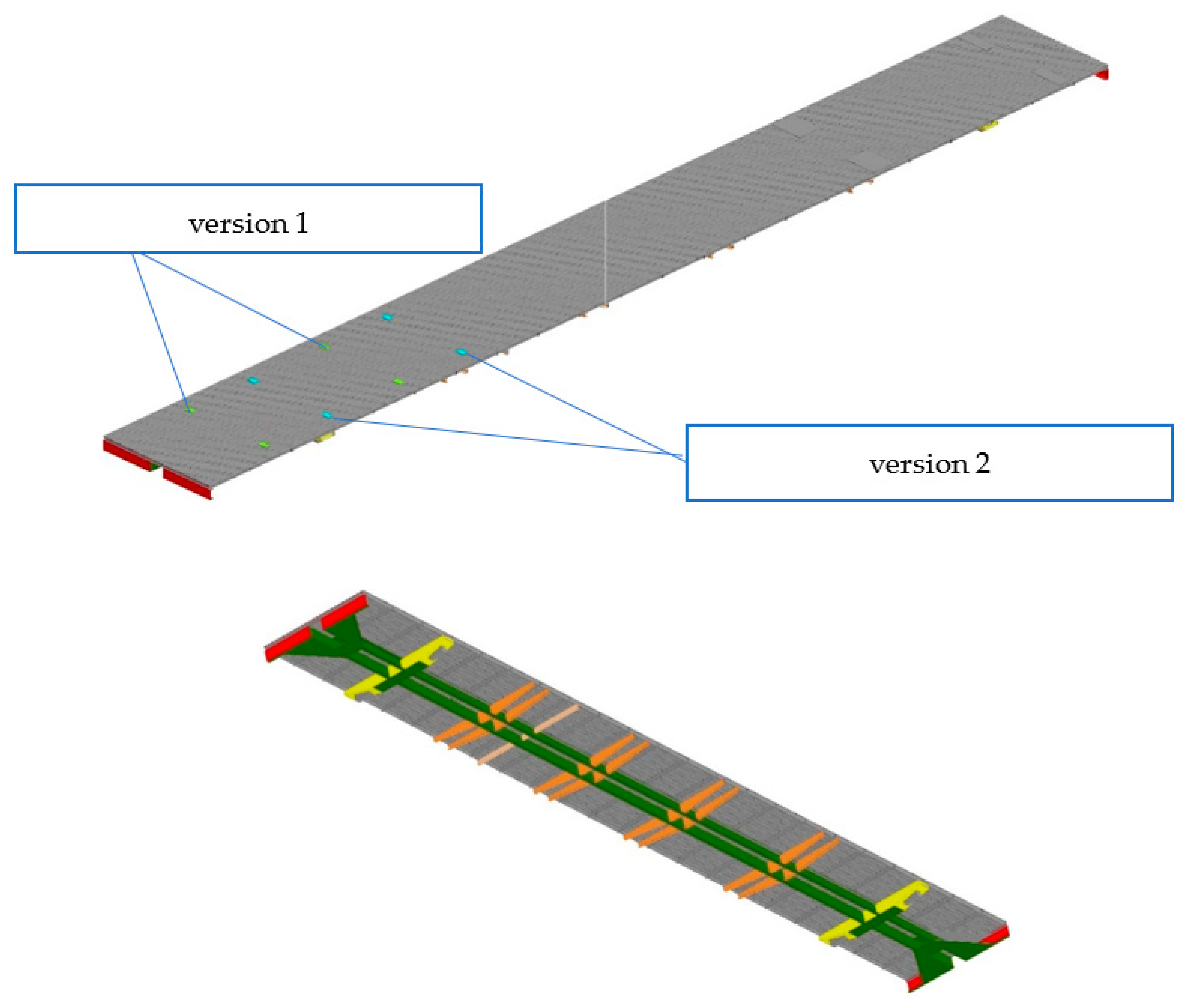
The body rests on two bogies of the KVZ-TsNII-1 model, designed for operation under passenger wagons on 1520 mm gauge main roads. To carry out the research, a model of the passenger wagon body was created using the finite element method (FEM). FEM was implemented using the ANSYS software package. The finite element method is a refined version of the displacement method, where the sought factors are considered to be elastic displacements of a deformed body [18]. The structure under study is represented by a deformable body, which is divided into finite elements (FE) connected by nodes and forms an FE design scheme. During the study, two types of design diagram of the passenger wagon body were considered (see Figure 1), as well as FEM (see Figure 2): 1) version 1 (extreme location of the wagon on board the wagon), 2) version 2 (with the wagon located closer to the center of the wagon).
When creating FE models, the characteristics of the isotropic material of the model were specified by the following values: Young’s modulus E = 2.1×10⁵ MN/m2, shear modulus G = 0.808 MN/m2, Poisson’s ratio μ = 0.3.
The boundary conditions for the calculation were specified as:
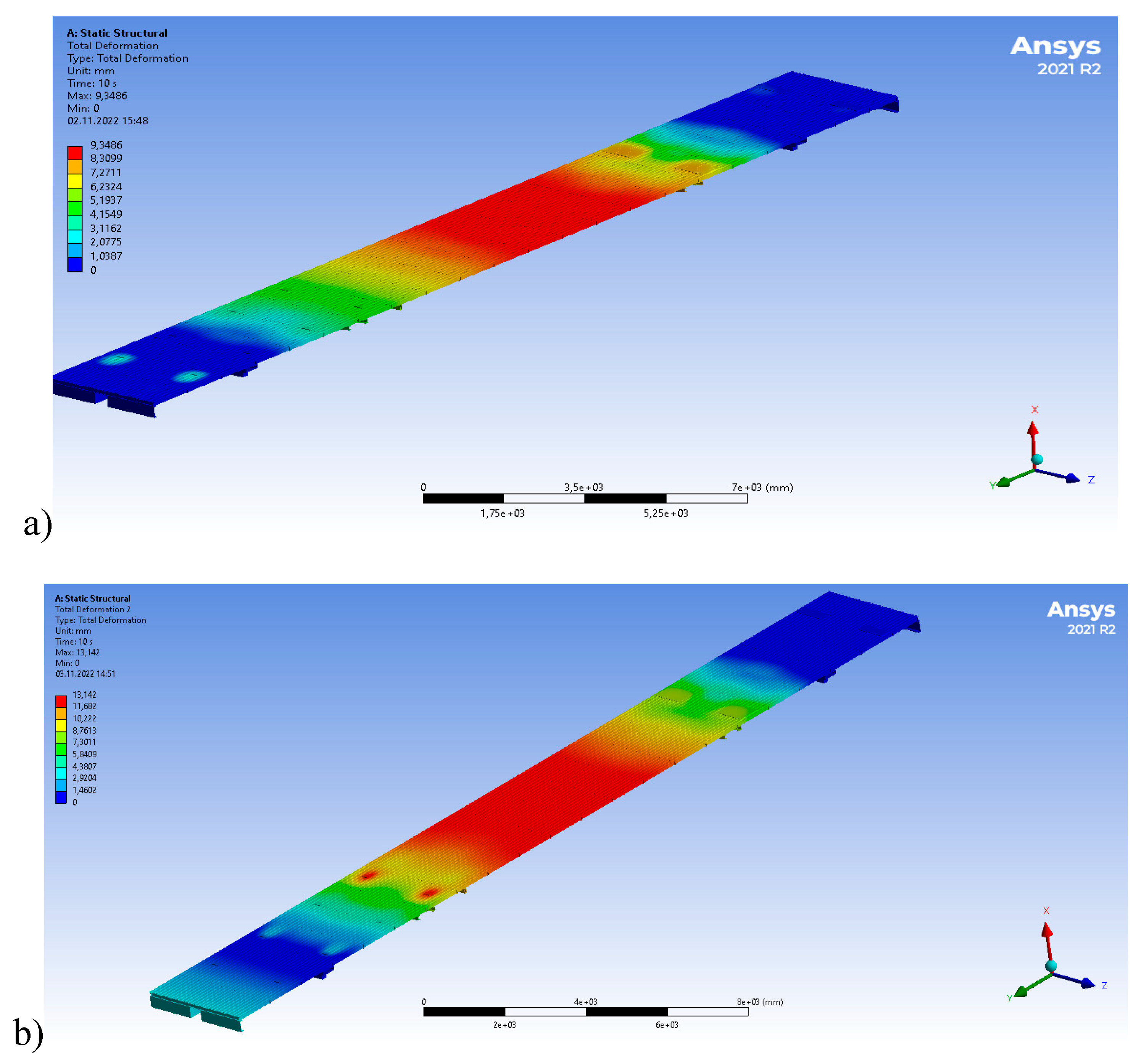
The body was supported on the platform and side slides, the vertical load was set identically to the weight characteristics carried out, 27 tons + 3 tons of vehicle weight, on the other hand, the distributed load of equipment and compartment rooms with a total weight of 30 tons. As a result of the mathematical modeling, the maximum values of elastic deformation in the vertical plane were calculated. Thus, the maximum values of elastic deflection deformation of the center beam (see Figure 3a) for design 1 was 9.34 mm, while for design 2 (see Figure 3b) it was 13 mm.
Figure 3. The greatest deformations of the wagon body: a) version 1; b) version 2.
Preprints 99152 g003
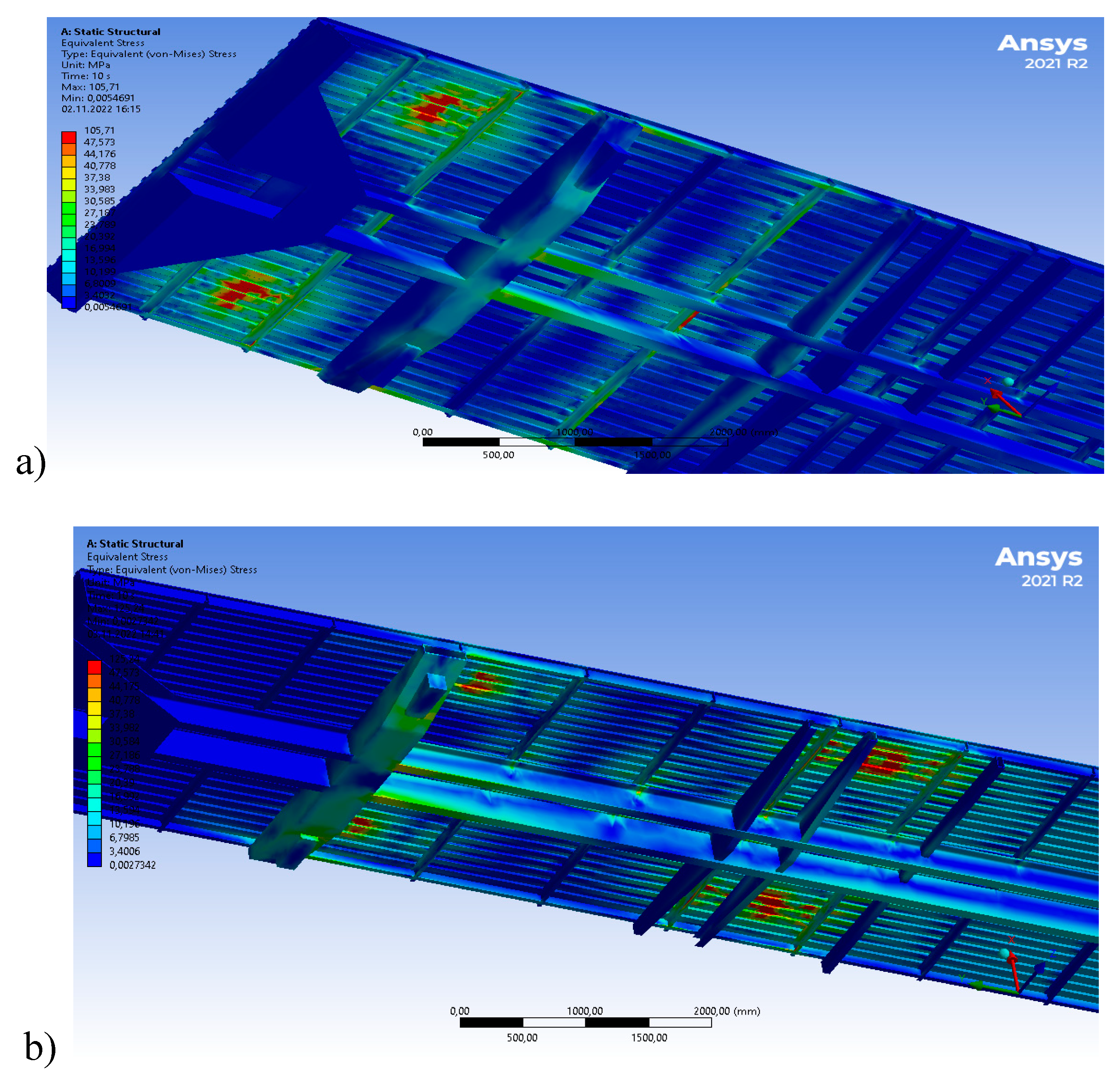
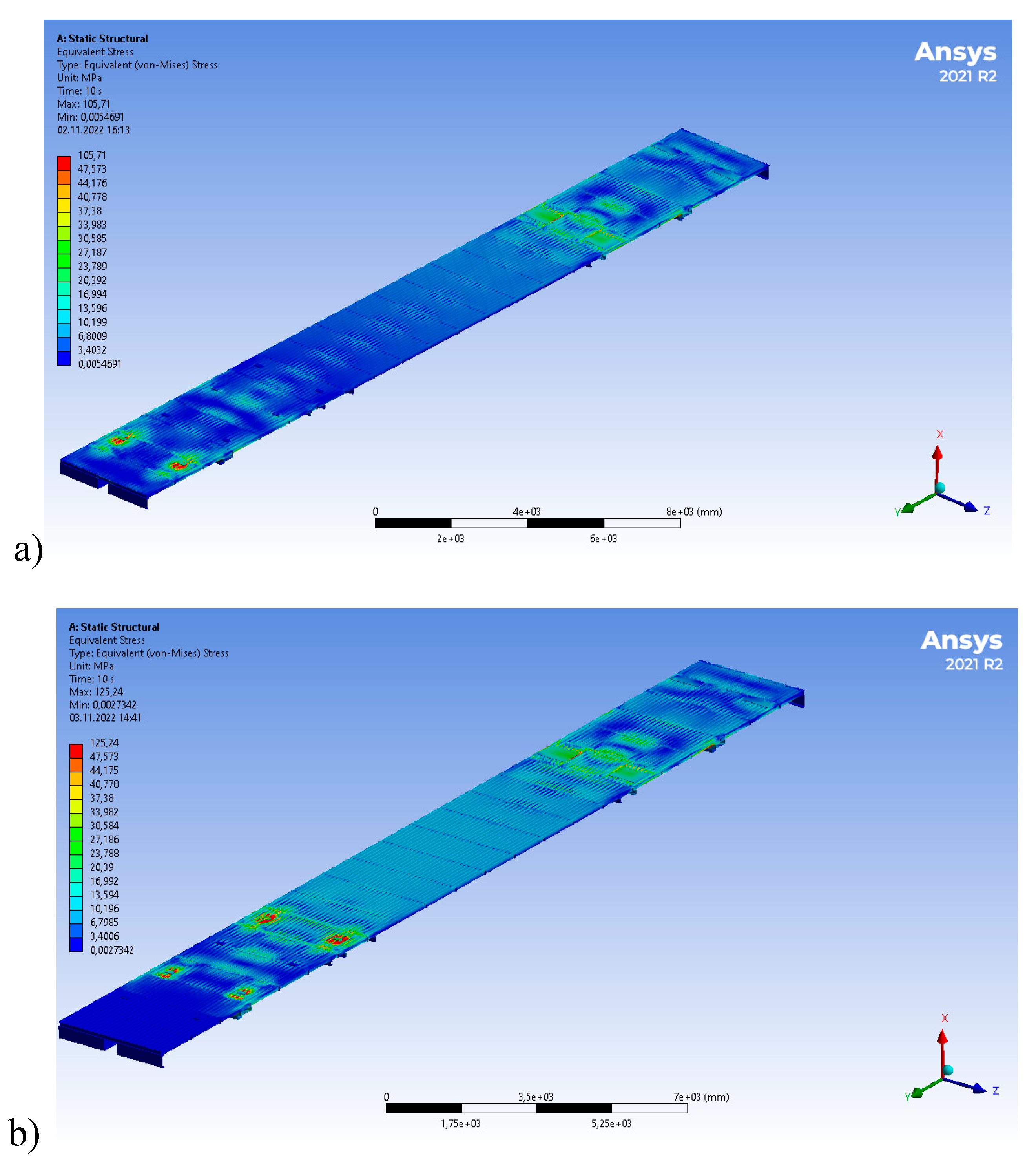
Figure 4. Equivalent stresses on the wagon floor: a) version 1; b) version 2.
Preprints 99152 g004
The difference in deformation of 3.66 mm is due to the fact that in version 1 the weight of the wagon falls in the area where the wagon body rests on the bogie, and in version 2 the weight of the wagon moves away from the support zone, thereby causing a greater deflection of the wagon body [19].
The equivalent stresses on the floor of the wagon for both version 1 and version 2 turned out to be around 47 MPa, these values are within the permissible limits and do not affect the service life of the wagon body [20].
The equivalent stress of the center beam for the 1st version in the area of the pivot beam was 105 MPa, with gradual dissipation closer to the center of the wagon up to 6 MPa, and for the 2nd version 125 MPa, at the junction with the pivot beam and dissipation up to 13 MPa closer to the center of the wagon. As can be seen from (see Figure 5b), the tension of the center beam for version 2 is maintained along the entire length, while for version 1 the tension is closer to zero [21].
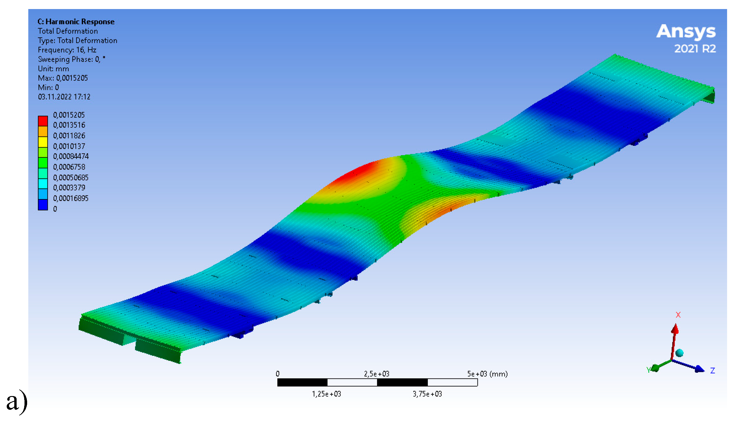
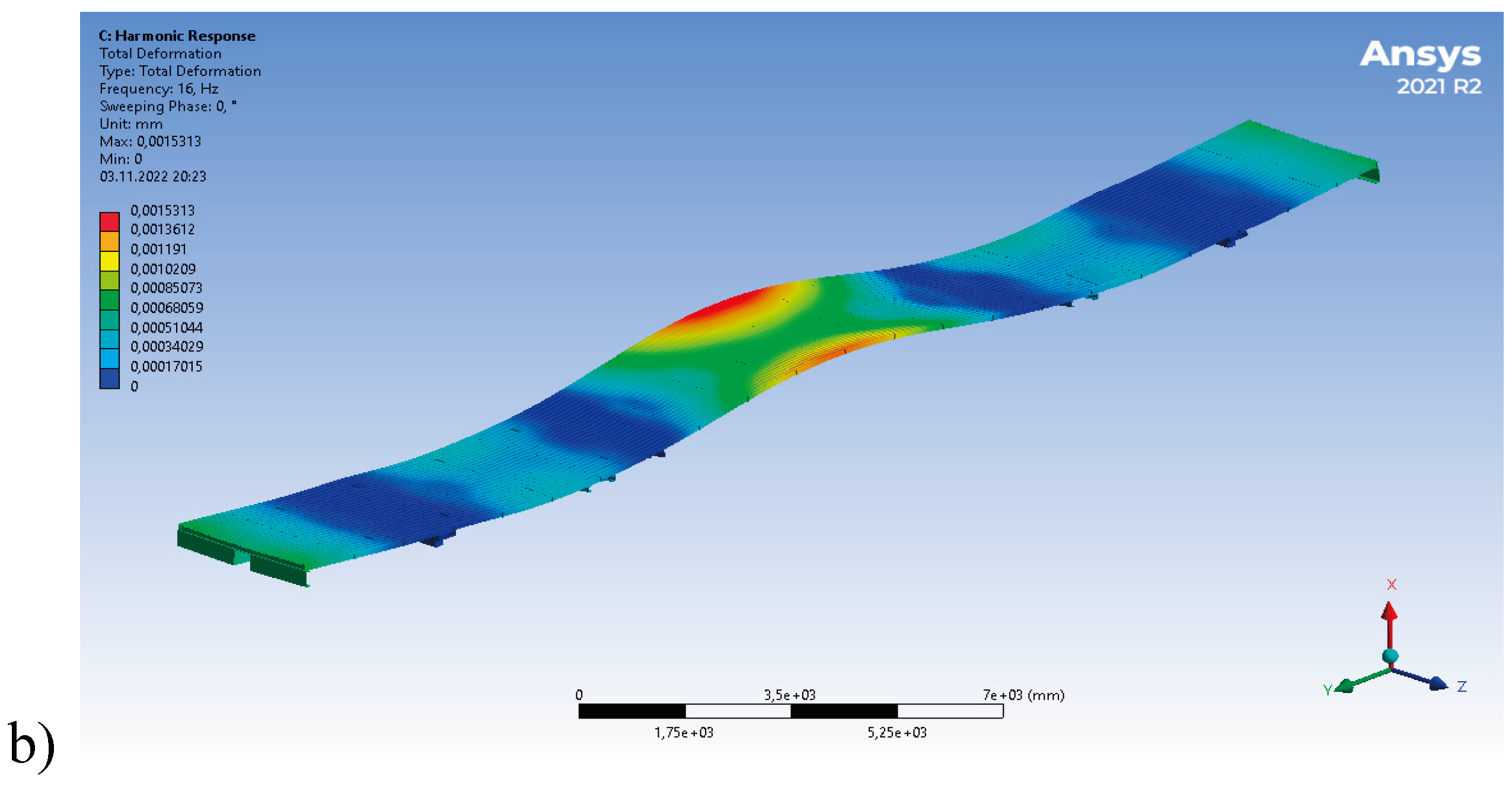
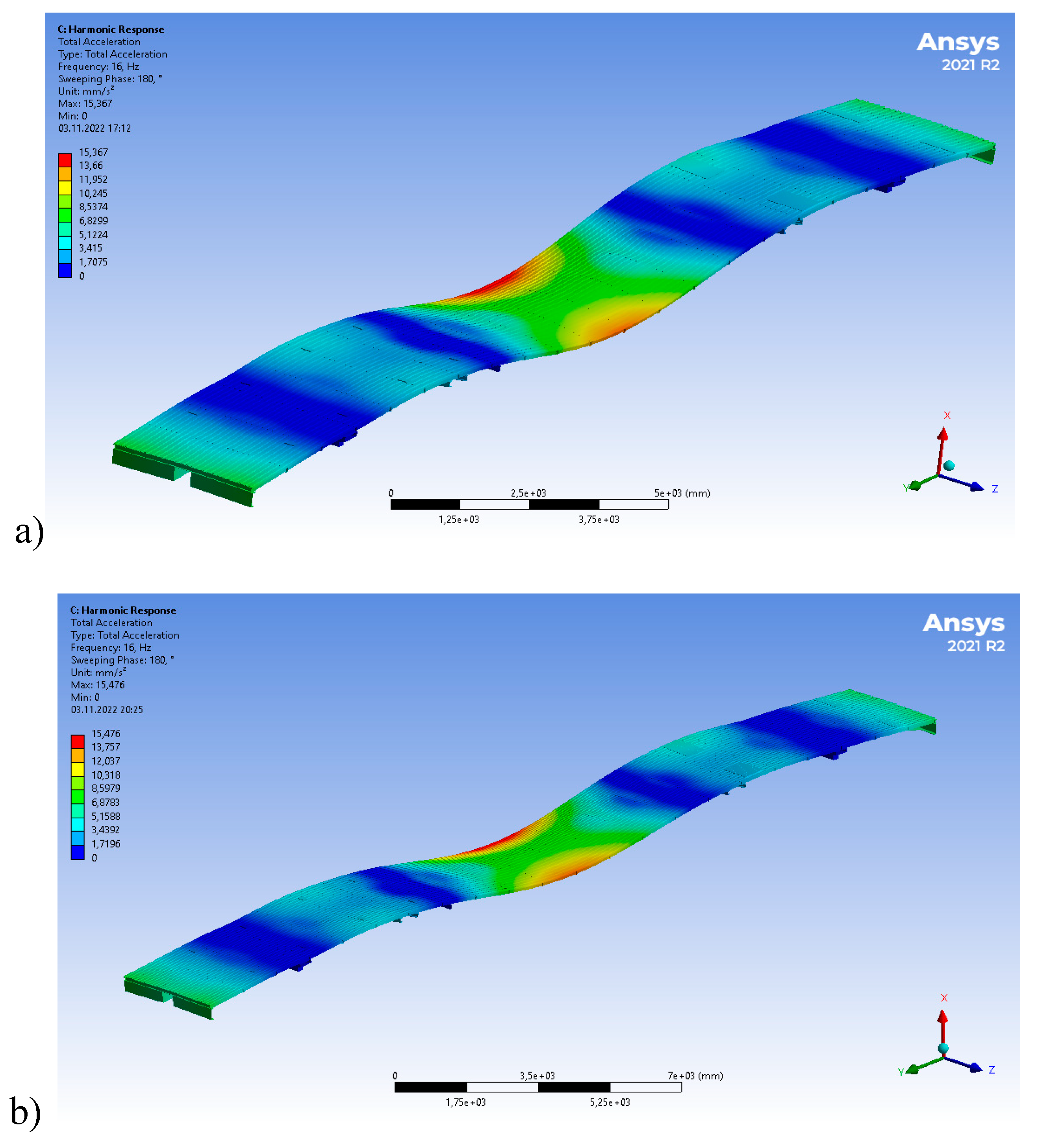
The calculation of the natural frequencies of vertical vibrations showed the identity of the vibration shapes (see Figure 6a,b), with a slight discrepancy in the vertical accelerations of the body (see Figure 7a,b), for 1st version 15.367 mm/s², and for 2nd version 15.476 mm/s².

4. Results and Discussion

4.1. Calculation of Indicators of Dynamic Qualities of a Modernized Wagon Model 61-4179 TVZ
When performing calculations of dynamic indicators of designed or modernized rail vehicles, the calculated values of the main dynamic indicators are compared with the standardized values [15,16]. Standardized values include: coefficient of vertical dynamics, coefficient of horizontal dynamics, safety factor of the wagon against overturning, safety factor of the wheel against derailment. These metrics are evaluated for different loading options. In this case, for a passenger wagon, this is the option of an empty wagon and a wagon with different weight settings from a wagon to 3 tons.
Let’s consider the calculation of the main standardized dynamic indicators of a passenger wagon using the example of a wagon model 61-4179.
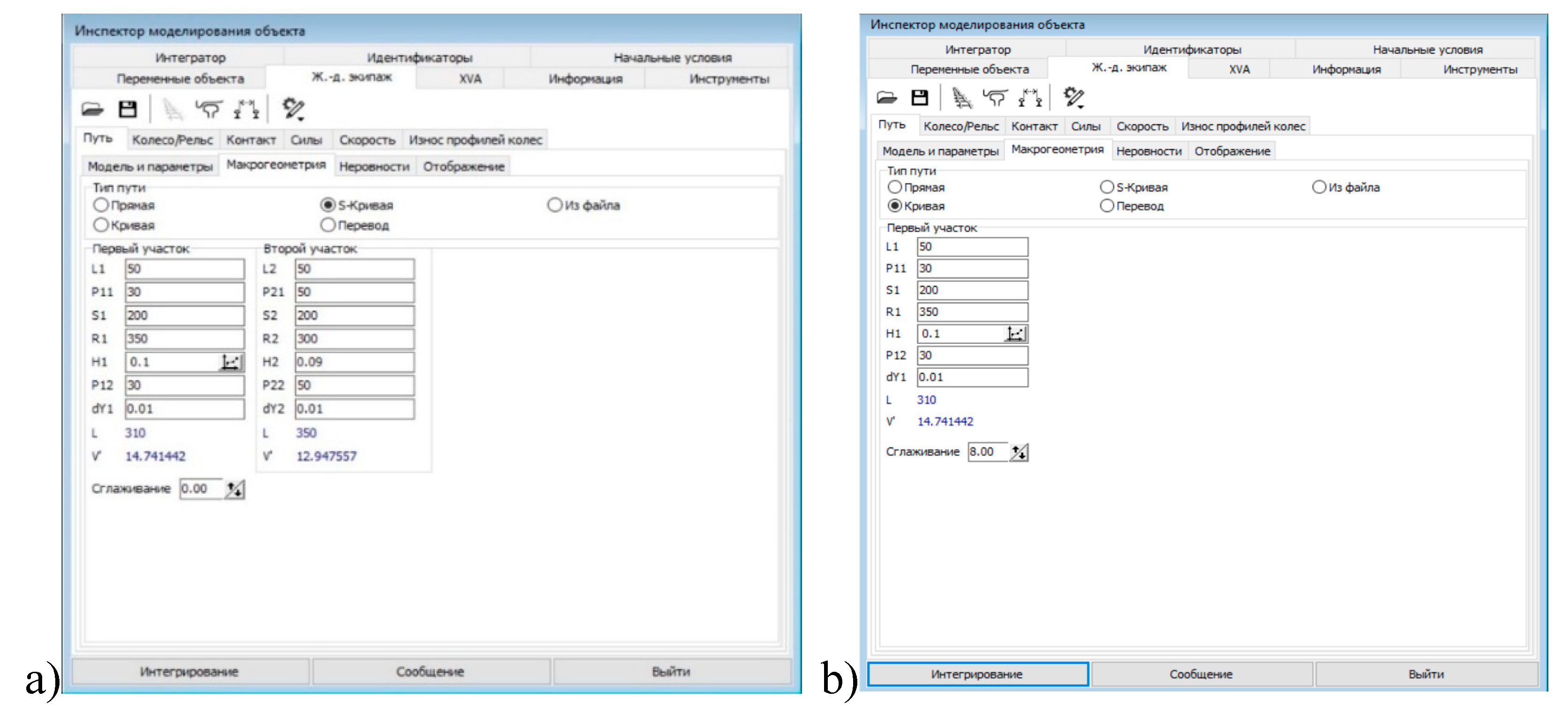
The dynamic properties of the wagon were calculated using the “Universal Mechanism” software package [17]. To carry out the calculations, models of the wagon were created with two different designs (1st version with the extreme location of the wagon on board the wagon, 2nd version with the location of the wagon closer to the center of the wagon).
Initial conditions for calculation:
Calculations were made for curved sections of the track, with and without taking into account irregularities on the rolling surface of the rails.
Figure 8. Macrogeometry of the path: a) S - shaped curve R1=350 m, R2=300 m; b) curve R=350 m.
Preprints 99152 g008
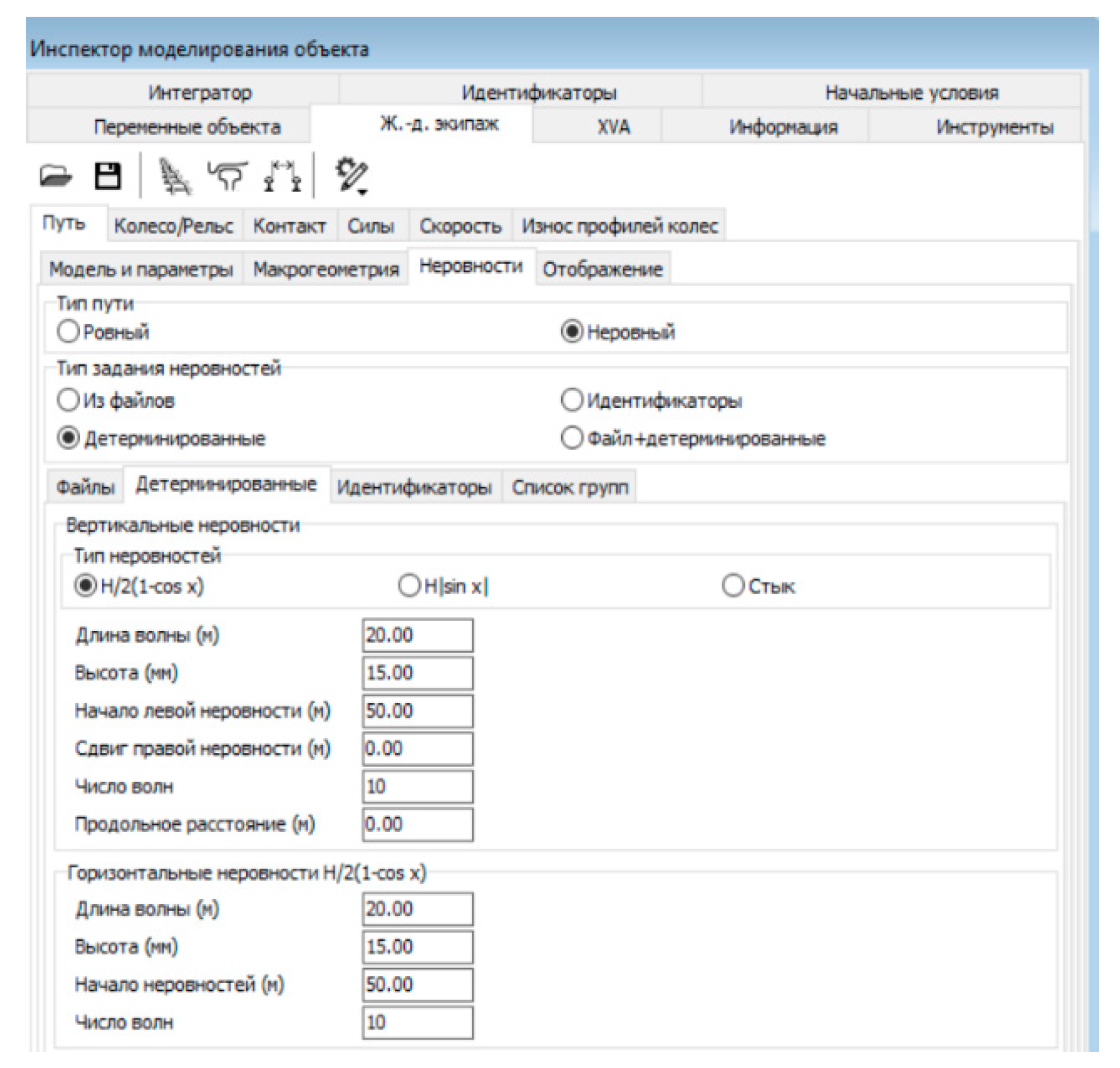
Figure 9. Vertical irregularities in the path.
Preprints 99152 g009
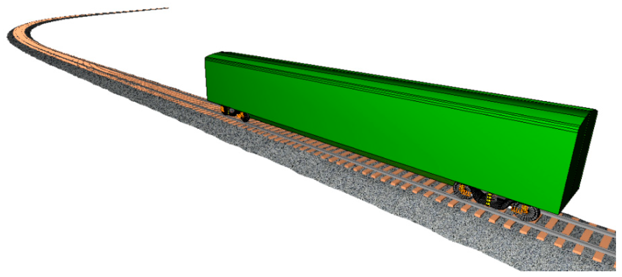
Figure 10. Graphic model of the wagon and track, curve R=350 m.
Preprints 99152 g010
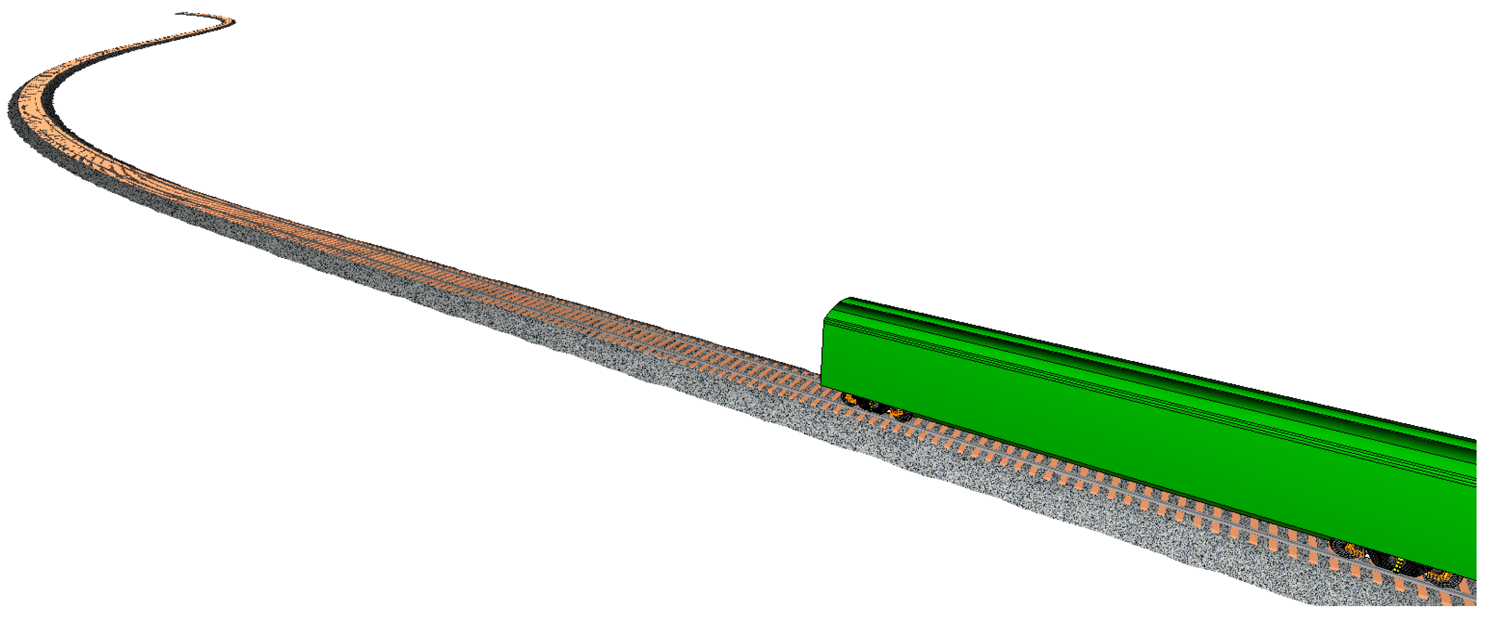
Figure 11. Graphic model of the wagon and track, S - shaped curve R1=350 m, R2=300 m.
Preprints 99152 g011
Table 1. Calculated indicators of the wagon.
No wagon on board With wagon on board 1 version With wagon on board 2-version
Mass - 57000.000 kg
Center of mass (0.000, 0.000, 0.982)
Moment of inertia (75600.1, 1984724.0, 1980614.0)
Mass - 60000.000 kg
Center of mass (0.594, 0.000, 1.083)
Moment of inertia (139514.4, 2329749.0, 2303352.0)
Mass - 60000.000 kg
Center of mass (0.468, 0.000, 1.083)
Moment of inertia (139514.4, 2235318.0, 2208920.0)
Conditions for completing Path - Path traveled
since the start of the simulation……..……….……….
Numerical method …………………………………….
Error ……………………………………………….……
Results recording step ………………………….….….
Calculation of Jacobian matrices ……………….……
List of variables ………………………………….…….
Speed …………………………………………………...
Path model ……………………………..………………
Creep force model …………………………………….

≥600
PARK
1E-6
0.005
yes
yes
60 km/h
Massless path
FASTSIM
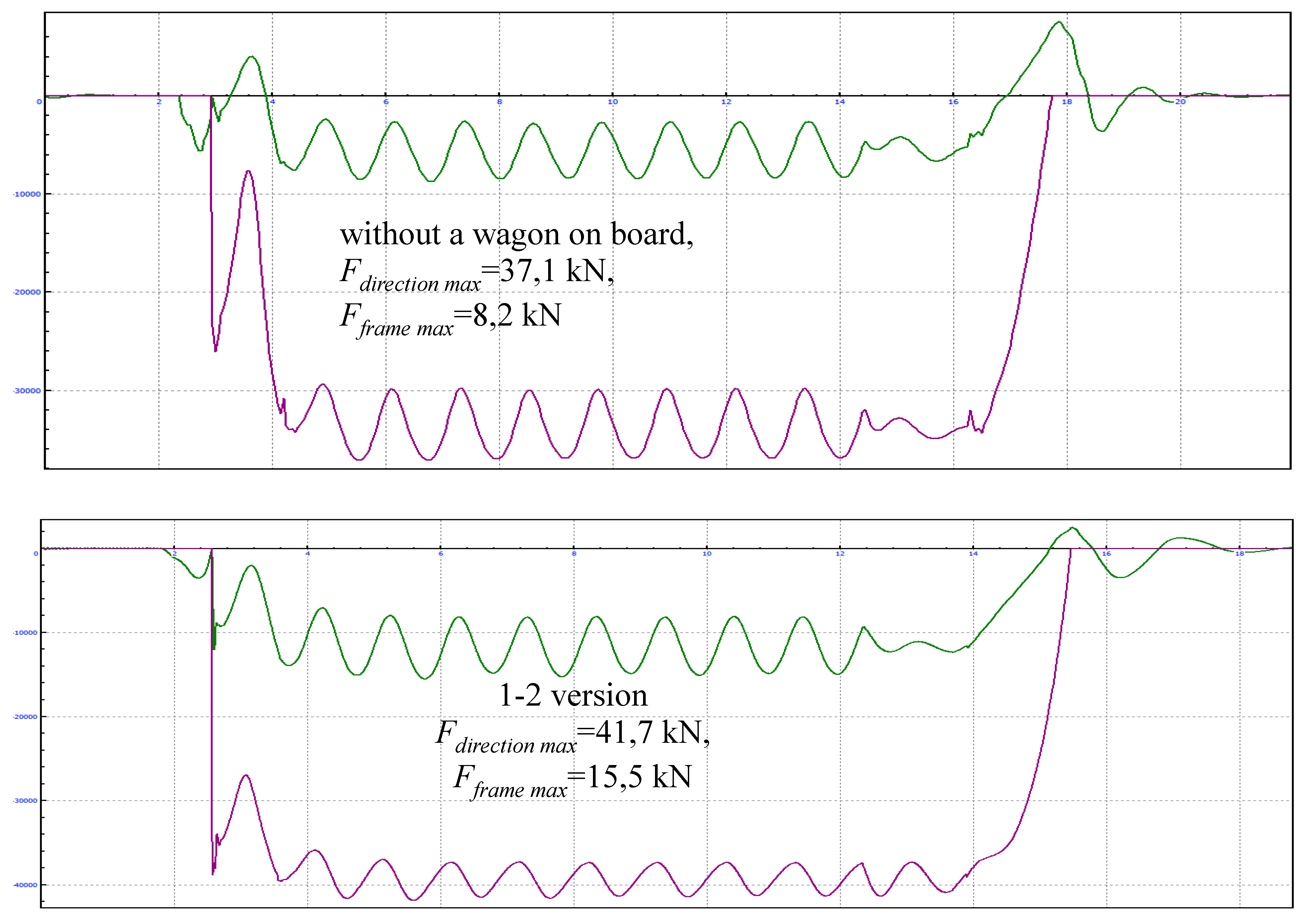
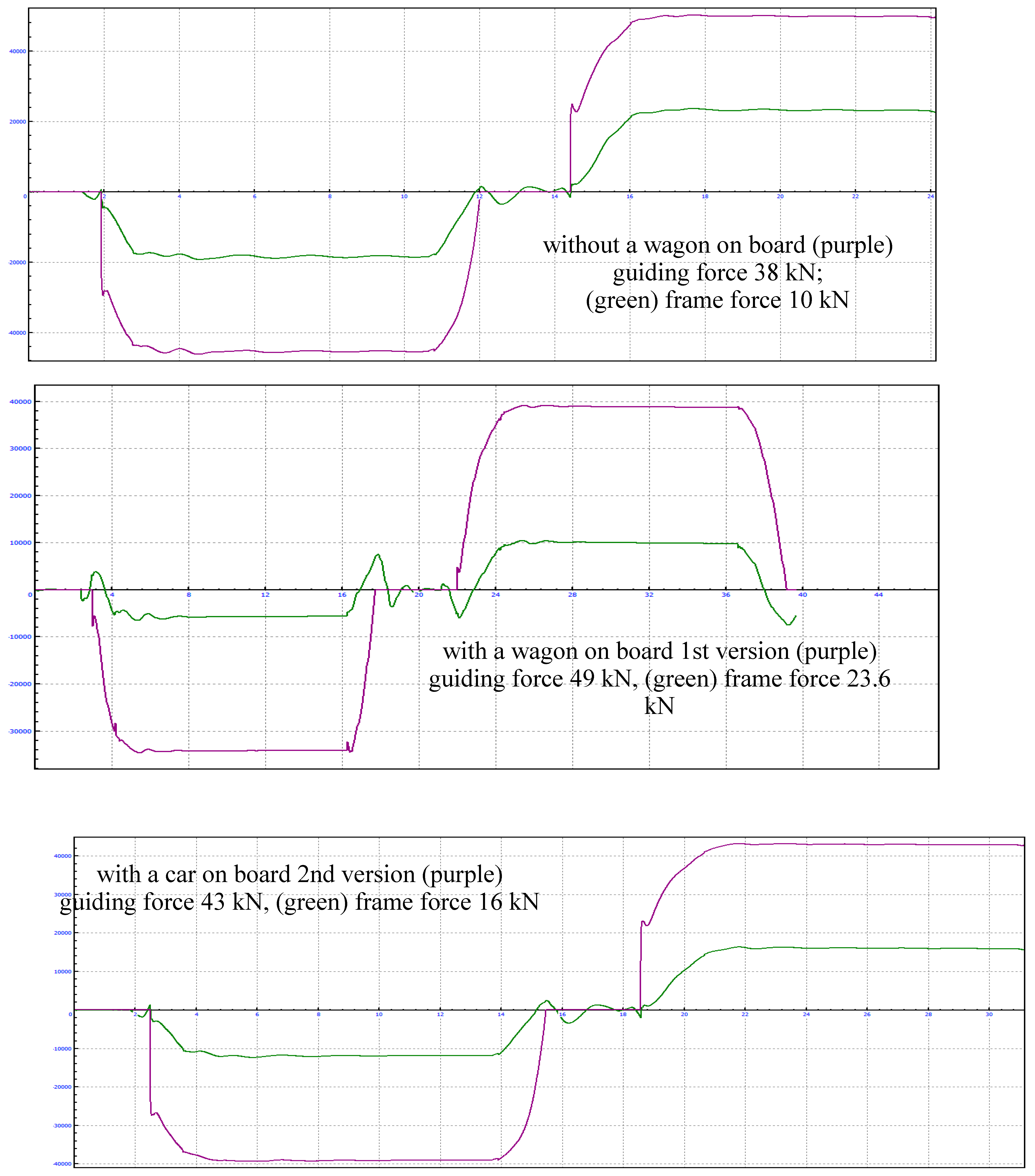
At the first stage, the frame forces arising during the passage of an S-shaped curve were determined, without taking into account track unevenness. In all 3 cases (see Figure 12) the force values are within the permissible limits with a large margin, however, it should be noted that the greatest forces arise in the 1st version 23.6 kN, which is 7.6 kN more than in the 2nd version th execution.
It should be noted that the indicated values were taken as the dependence of the greatest forces on R2 = 300 m, at a speed of 60 km/h.
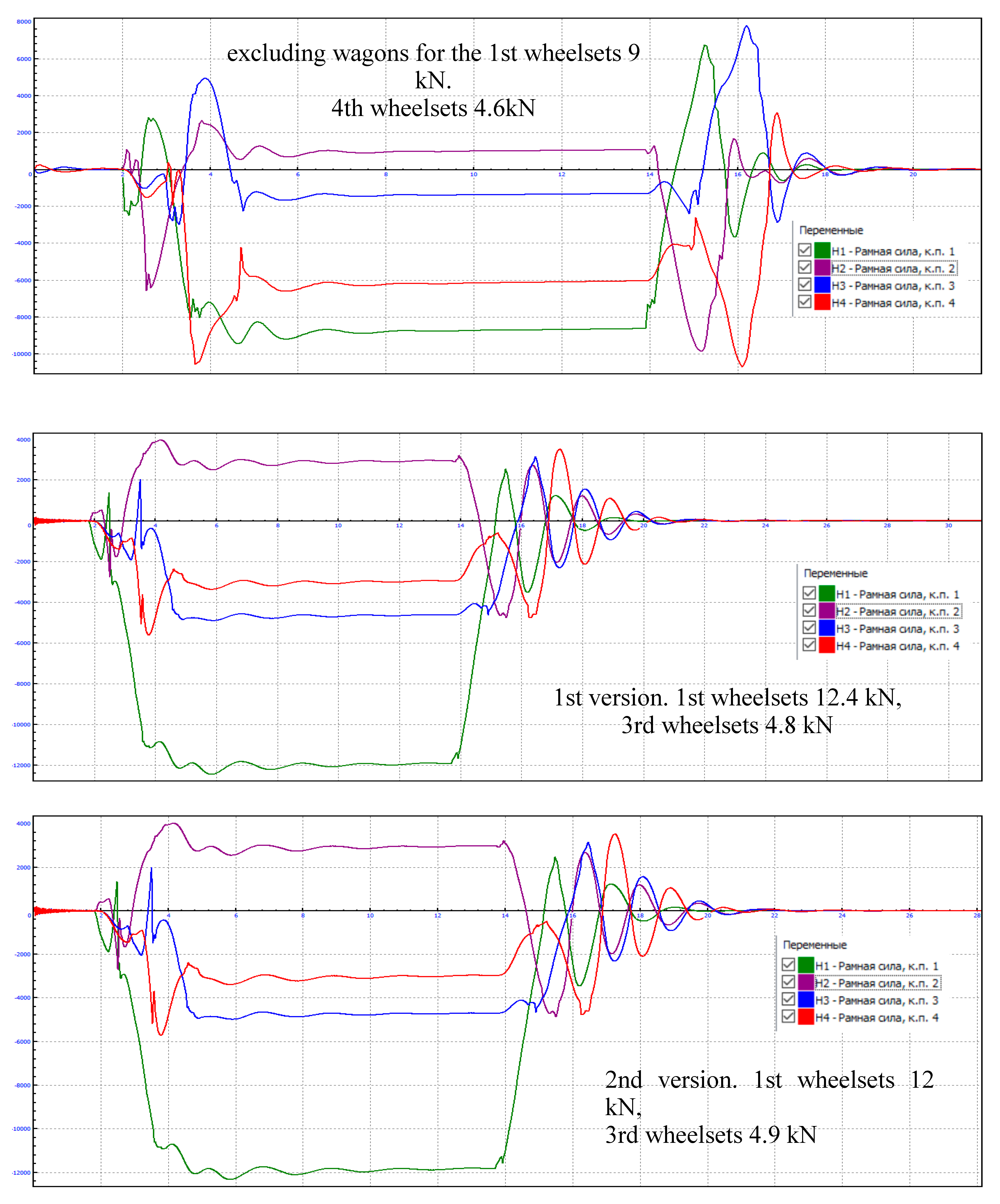
Next, the frame forces occurring when passing a curve with a radius of 350 m were calculated. For comparison, the graphs show all wheel sets (see Figure 13). For a wagon without loading, the highest values of frame forces occurred at the 1st and 4th wheelsets. and have a spasmodic character, with maximum values at the entrance and exit from the curve, while the 1st and 2nd executions have the highest value at the first point. in the direction of movement. In all 3 cases, the force values are also within the acceptable range with a large margin [22].
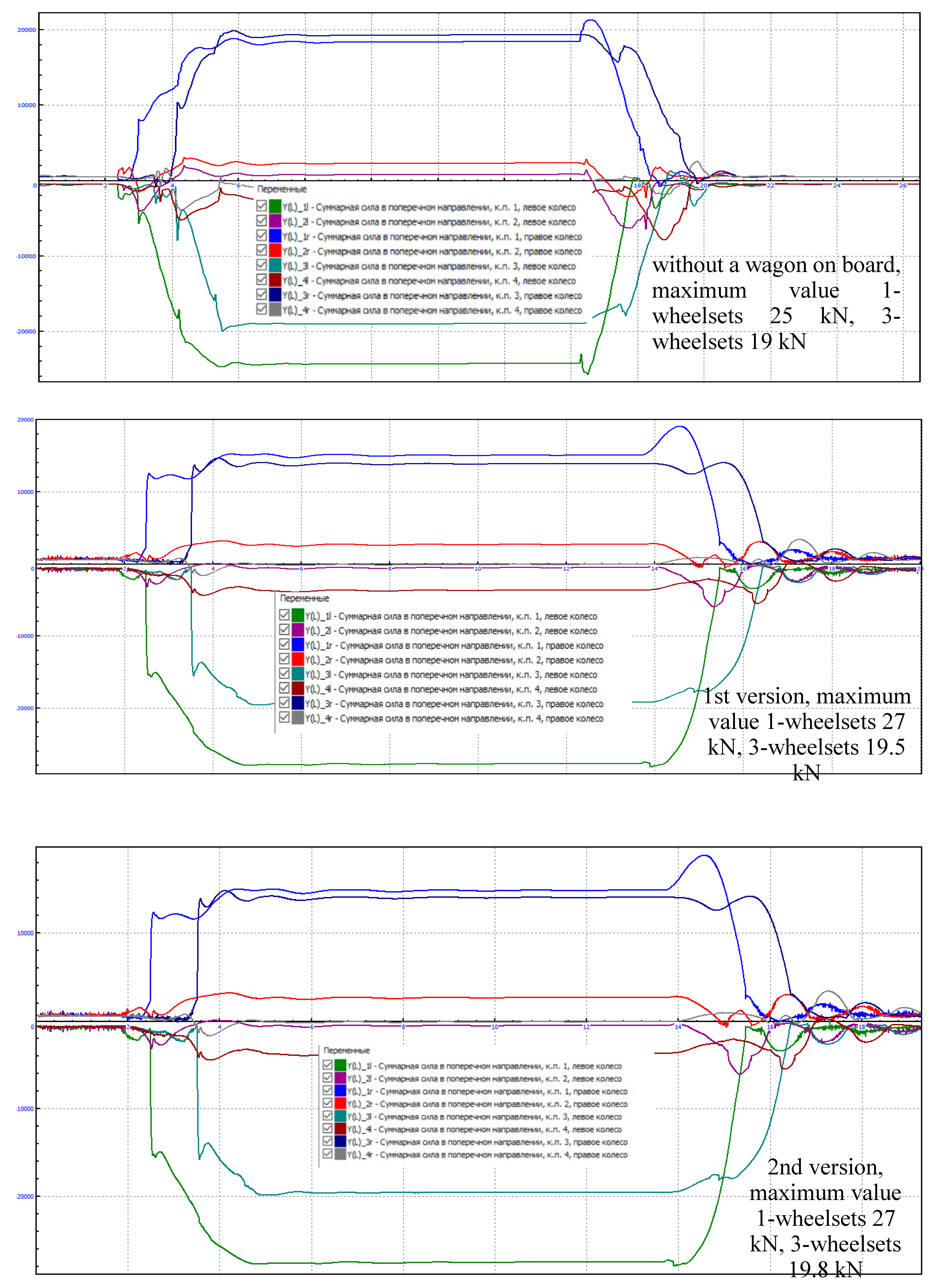
Total forces in the transverse direction (see Figure 14). In all 3 cases, the force values are within acceptable limits with a large margin. So for all 3 models the value of forces from the 1st wheelsets are the largest and range from 25-27 kN. The next highest values were obtained for 3 wheelsets. 19-19.8 kN.
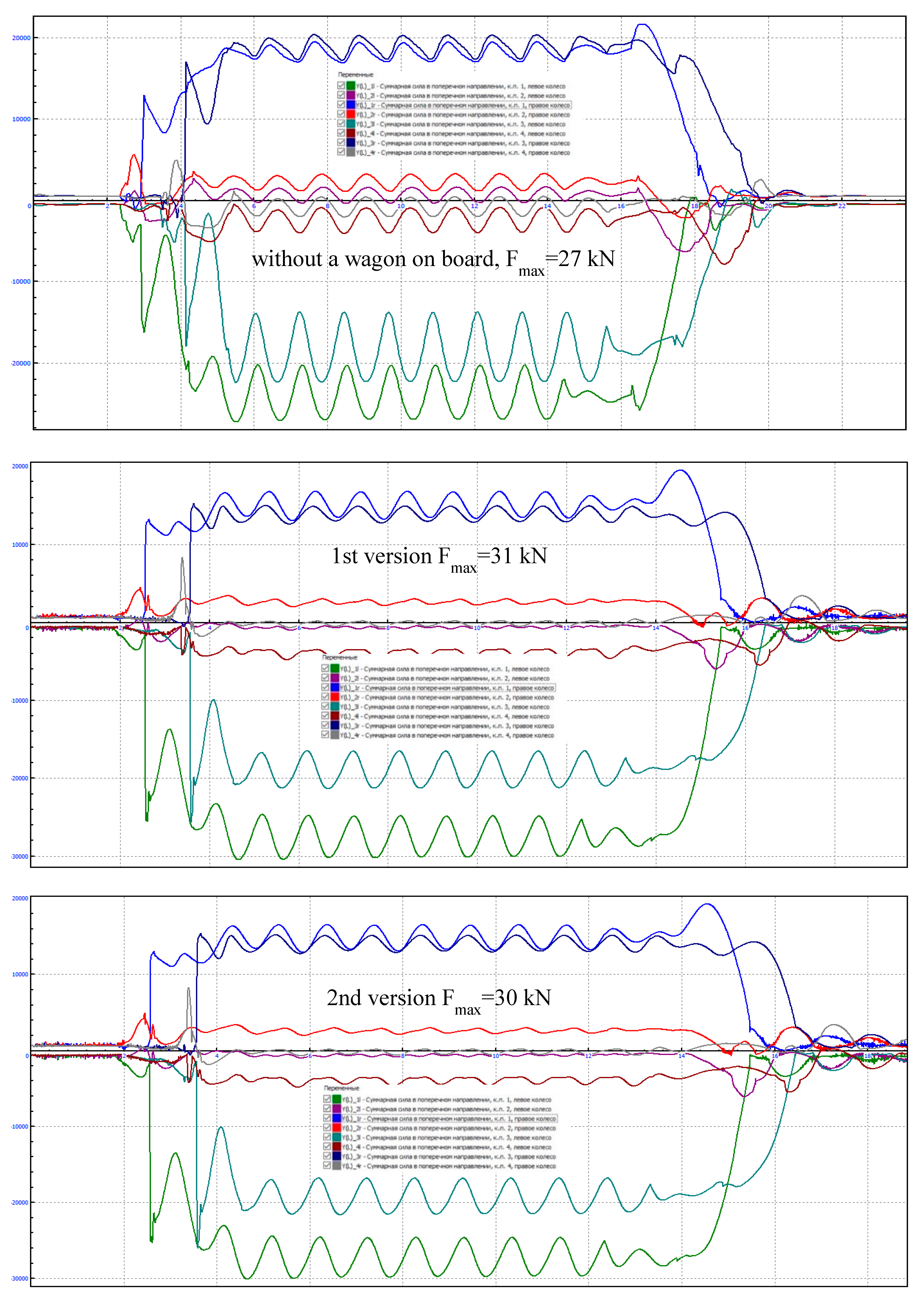
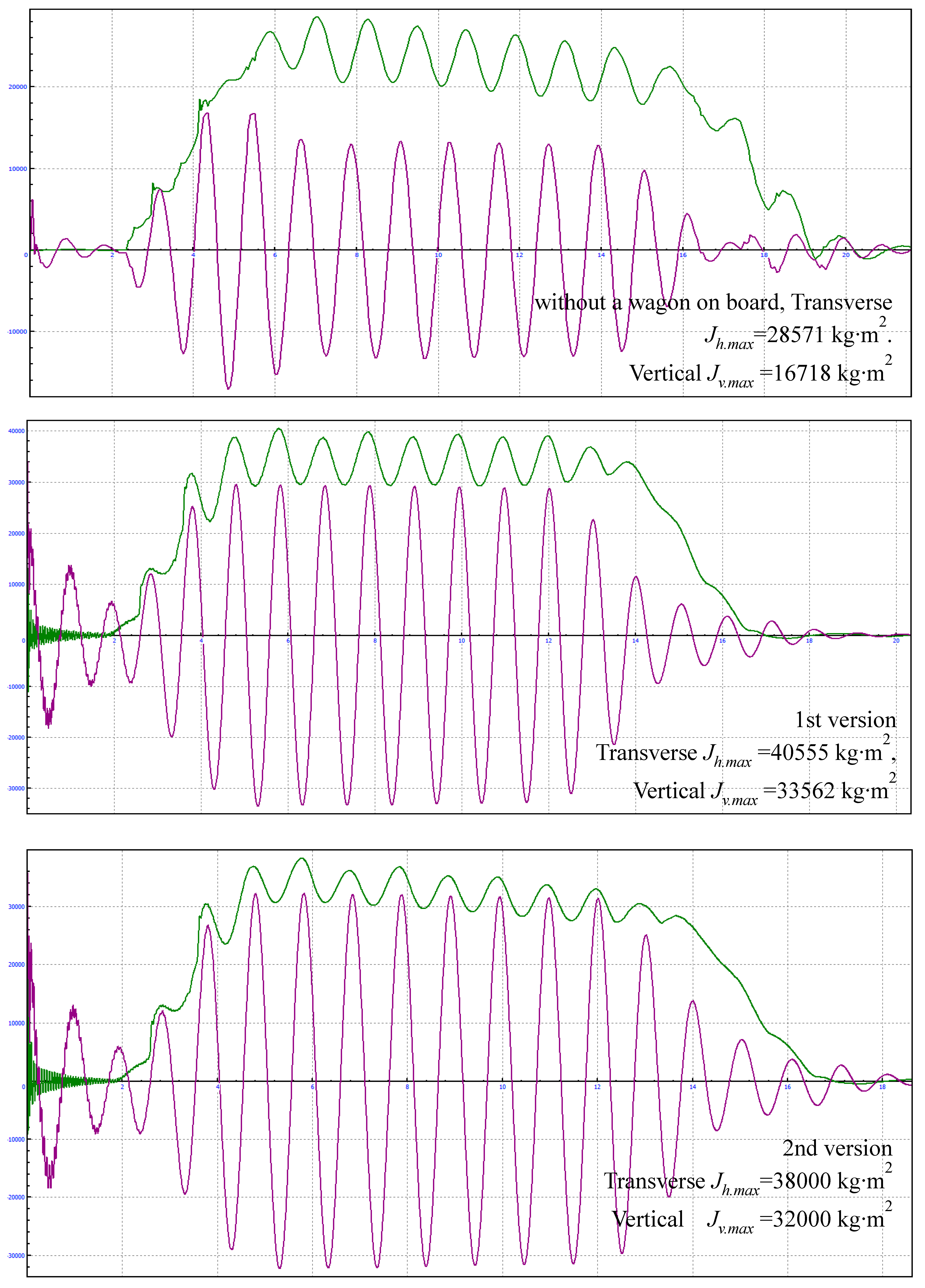
The total forces acting in the transverse direction, in a curve with a radius of R350 m, taking into account irregularities (see Figure 15). The highest total lateral forces for the 1st and 2nd versions are within 30-31 kN, and for a carriage excluding wagons 27 kN. This is on average 3 kN more than on the path without taking into account irregularities.
Figure 15. Dependence of the total forces in the transverse direction on the curve, taking into account irregularities.
Preprints 99152 g015
Figure 16. Inertia forces of the wagon body.
Preprints 99152 g016
Figure 17. Dependence of frame forces on the distance traveled in a curve with a radius of 350 m, taking into account irregularities.
Preprints 99152 g017
The coefficient of vertical dynamics kvd is considered in [19] as a random function with a probability distribution of the form:
P k v d = 1 exp π 4 k v d 2 k v d 2 β 2
The coefficient kvd is defined as the quantile of this function with the calculated one-sided probability P(kvd) according to the formula:
k v d = k ¯ v d π 4 π ln 1 1 P k v d
where kvd – is the average probable value of the vertical dynamics coefficient.
k ¯ v d = α + 3,6 10 4 b V 15 f s t i
where a – is the coefficient equal to 0.05 for body elements; b – is the coefficient taking into account the influence of the number of axles n = 2 in a bogie or a group of bogies under one end of the carriage.
b = n + 2 2 n = 2 + 2 2 2 = 1
where V – is the design speed; f с . т i – is the static deflection of the spring suspension of a carriage with passengers.
Figure 18. Vertical dynamics coefficient.
Preprints 99152 g018
Figure 19. Dependence of the approach angle of wheelsets on the passage of a curved section of the track.
Preprints 99152 g019
Vertical and horizontal inertia forces of bodies, for R350 m curves, taking into account unevenness. The inertial components of the body in the vertical and horizontal planes, taking into account disturbing factors [20], turned out to be the largest for the 1st version of the body, and the smallest, respectively, without taking into account the load of the car. Inertial forces are also within the permissible limits according to the requirements of GOST 34759-2021. Frame and guiding forces from the 1st wheelstes in the direction of movement, taking into account unevenness on the rail rolling surface. As can be seen from the graphs (see Figure 17), disturbing factors in the form of track irregularities negatively affect the level of frame forces. So, if without taking into account unevenness the maximum values of frame forces are within 12.4 kN, then taking into account unevenness it was 15.5 kN. However, it should be noted that even taking into account the unevenness of the track, the frame forces when passing a car along a curve with a radius of 350 m are within acceptable limits.
Table 2. Standard values kvd.
Assessment of wagon progress Vertical dynamics coefficient of the wagon
Excellent
Good
Satisfactory
Permissible
Unsuitable
0,1
0,15
0,20
0,35
0,70
Vertical dynamics coefficient of the wagon. in accordance with [9]:
For a without a wagon on board: k v d = 0,13 k v d .
For a 1st and 2nd version of the wagon travel is permissible: k v d = 0,29 k v d .
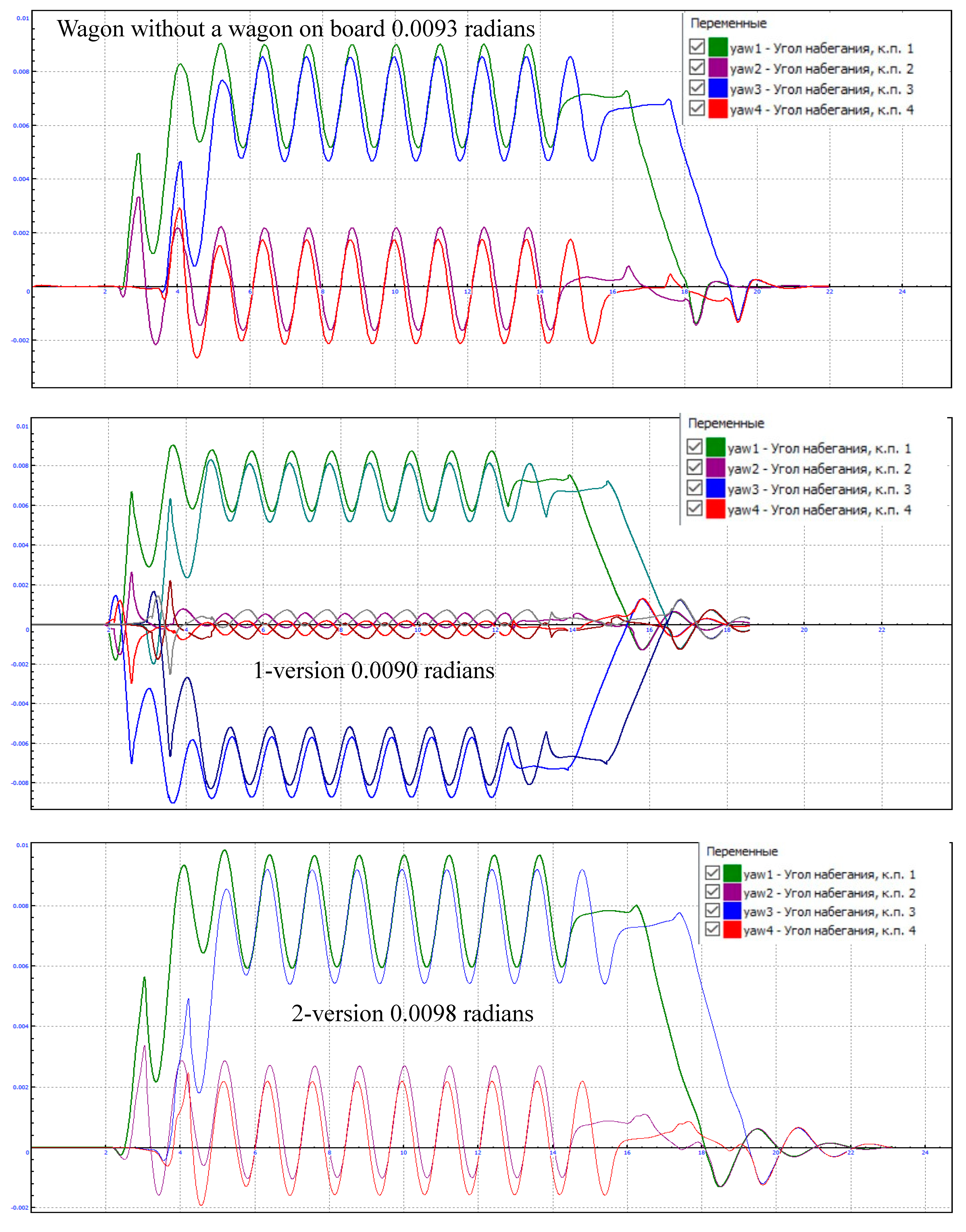
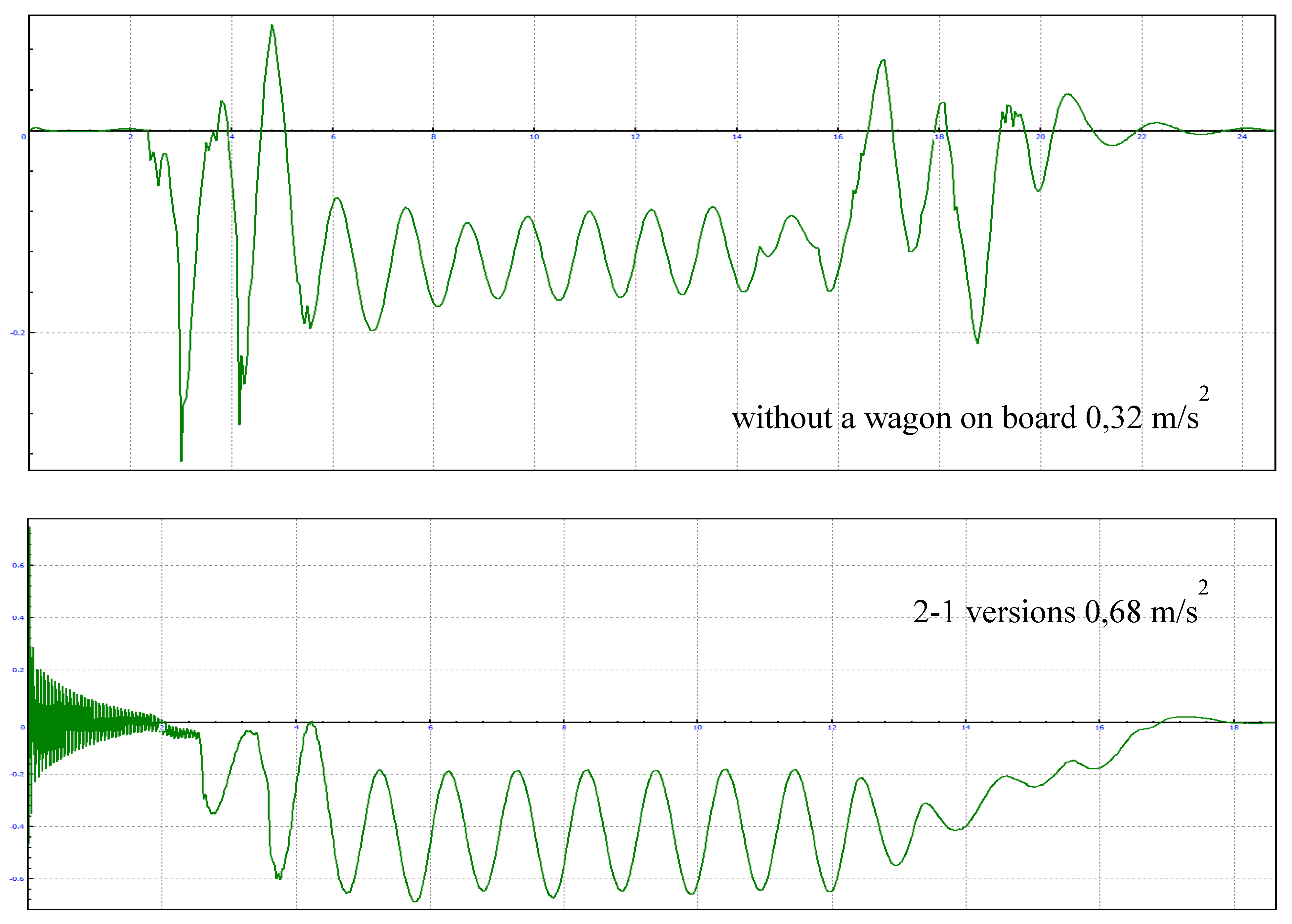
The approach angle of the wheelsets in all 3 options does not exceed 0.01 radians, which is a normatively acceptable value. The magnitude of the outstanding acceleration of the wagon body (see Figure 20) when passing a curved section of track with a radius of 350 m, at a speed of 60 km/h.
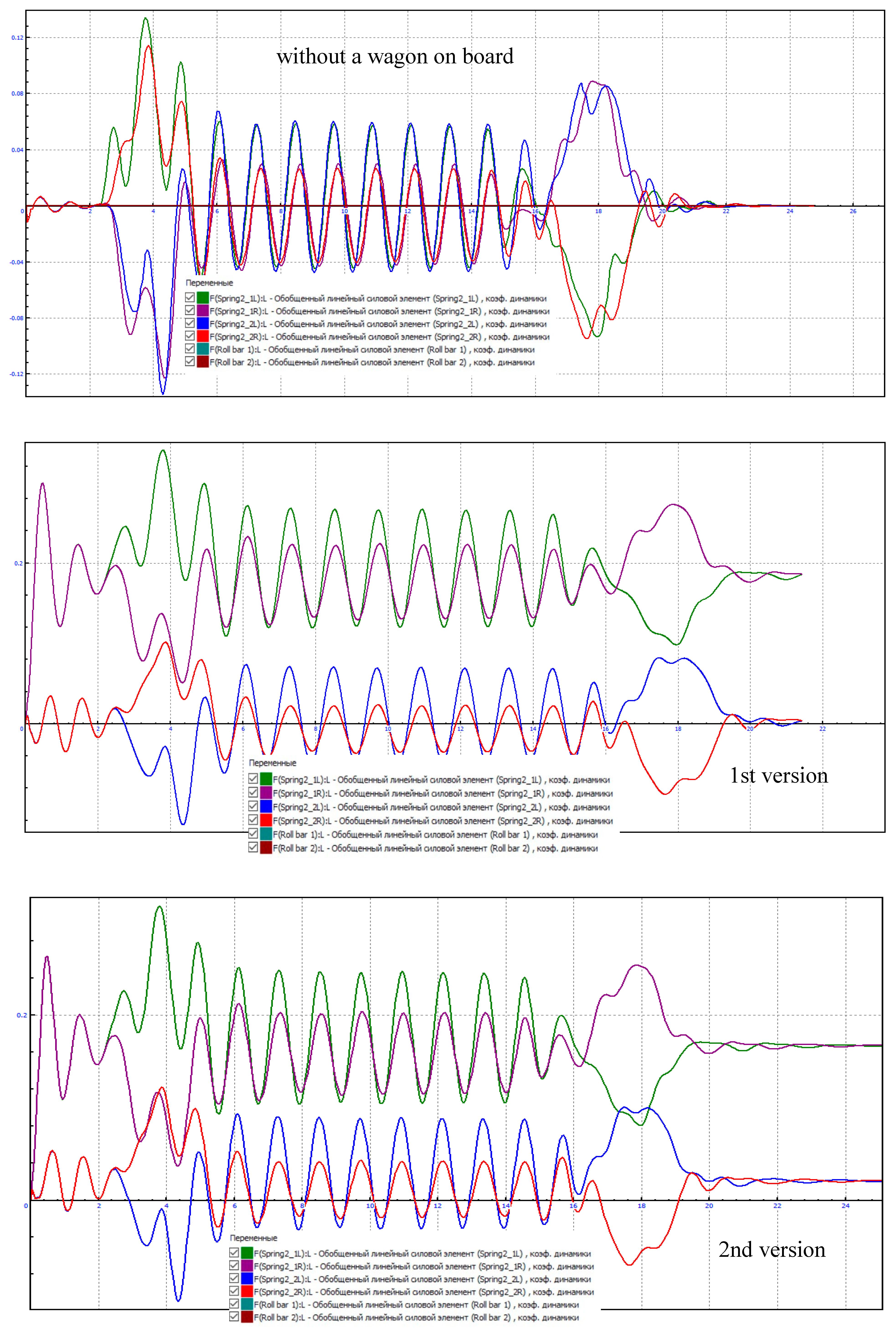
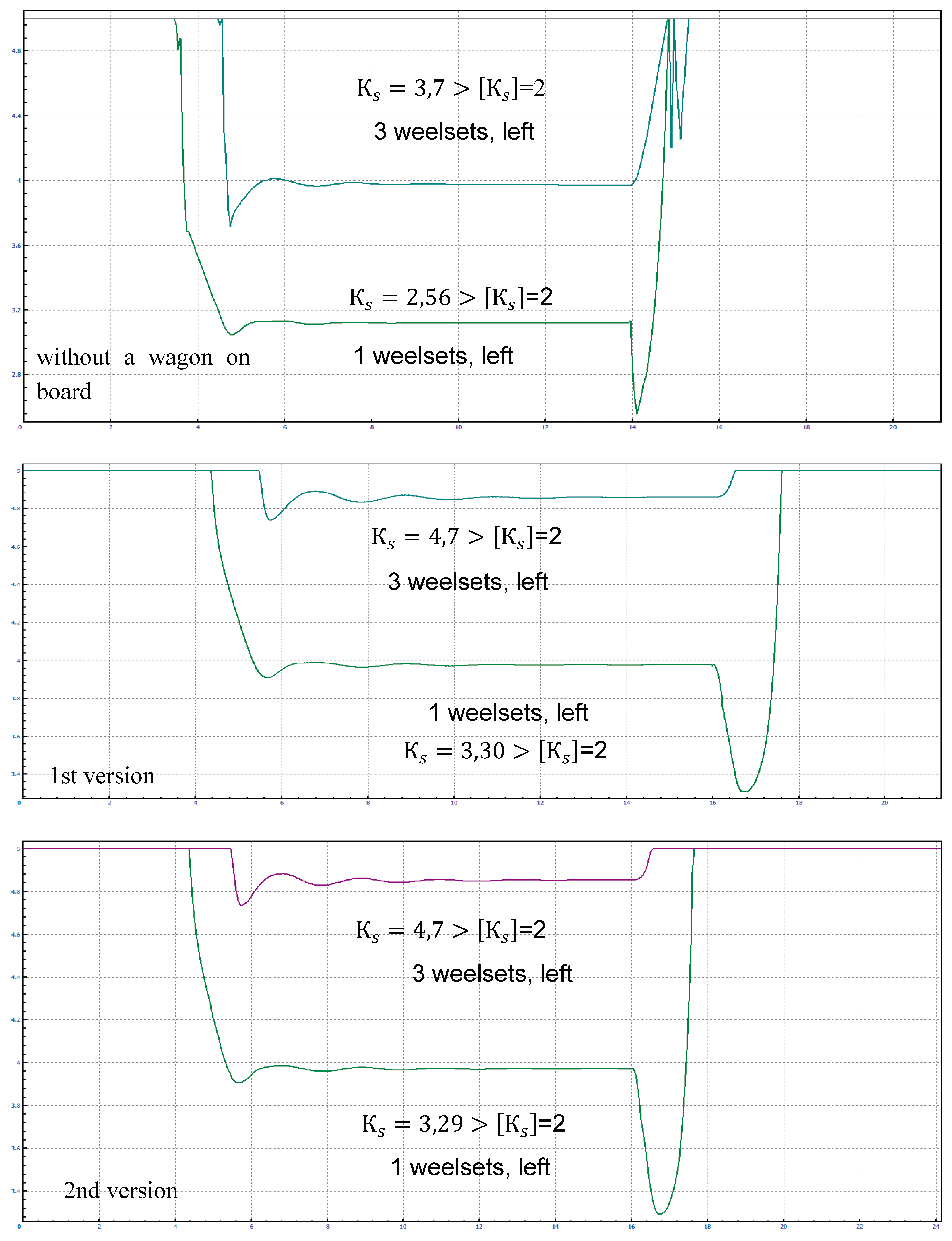
The outstanding acceleration of the wagon body for both the 1st and 2nd versions turned out to be identical 0.68 m/s2 < [0.7], which does not exceed the minimum permissible values for the acceleration of the passenger wagon body [21,22]. The graph (see Figure 21) shows the 1st and 3rd wheelsets of the wagon in the direction of travel. 2nd and 4th wheelsets are not given due to the increased margin of stability against derailment.

5. Conclusions

1) Based on the results of the calculations, it can be seen that the stress strain state (SSS) for both versions do not differ significantly. However, it should be noted that the SSS indicators of the 1st version are lower compared to the 2nd version. This is explained by the fact that with the 2nd version the weight of the wagon is located closer to the center of the wagon and moves away from the support area of the pivot beam, thereby bending the center beam of the wagon more. This is confirmed by Figure 3, where the deflection of the 1st version is 9 mm, and the 2nd is 13 mm.
2) As for the influence of additional cargo in the form of a wagon weighing 3 tons on the performance and durability of the center beam, they are within the permissible limits σp = 105-125 > σp = [160], which is confirmed Figure 4 and Figure 5, and the stress intensity on the floor of the 1st and 2nd design wagons was 47 MPa.
3) Analysis of natural frequencies and vertical vibrations for both the 1st and 2nd versions are within acceptable limits.
4) The vertical acceleration of the wagon body for the 1st version was 15.367 mm/s², and for the 2nd version 15.476 mm/s².
5) Vertical dynamics coefficient:
for a without a wagon on board: k v d = 0,13 k v d
for a 1st and 2nd version of the wagon travel is permissible: k v d = 0,29 k v d
6) Factor of safety margin for a car against capsizing:
for a without a wagon on board: k S R = 1,42 k S R = 1,4
for a 1st and 2nd version of the wagon travel is permissible: k S R = 1,43 k S R = 1,4
7) Wheelsets stability coefficient against derailment:
for a without a wagon on board 1st weelsets: k S = 2,56 k S = 2
3rd weelsets: k S = 3,7 k S = 2
Car with a car on board:
1st version k S = 3,29 k S = 2
2nd version k S = 4,7 k S = 2
The condition for the wheel stability margin against derailment is met. Thus, all normalized dynamic indicators of the MDC car considered for modernization, both for version 1 and for version 2, do not exceed the permissible values, and the stability indicators have a sufficient margin, which indicates the good running properties of the car. Taking into account the previously carried out strength calculations, as well as in order to maintain the factory life cycle indicators of the supporting structure of the car body, it is recommended to use model 1.

Author Contributions

Conceptualisation, J.M.; methodology, Z.I. and A.Z.; software, J.M.; validation, A.A. and G.B.; formal analysis, A.Z. and J.M.; investigation, T.C. and J.M.; resources, G.S. and G.B.; data curation, G.S. and A.A.; writing—original draft preparation, G.S., G.B., A.A. and A.Z.; writing—review and editing, J.M., A.A.; T.C. and Z.I.; visualisation, V.S. and K.A.; supervision, J.M.; project administration, S.Z.; T.C.; A.Z. and J.M.; funding acquisition, Z.I.; G.S.; G.B. and A.A.; All authors have read and agreed to the published version of the manuscript.

Funding

This research received no external funding.

Institutional Review Board Statement

The study did not require ethical approval.

Informed Consent Statement

Not applicable.

Data Availability Statement

Data are contained within the article.

Acknowledgements

This work was carried out in the research laboratory of the Institute of Civil Engineering of the Academy of Logistics and Transport, for which the authors are grateful.

Conflicts of Interest

The authors confirm that they have no conflict of interest with respect to the work described in this manuscript.

References

  1. Musayev, J.; Abilkaiyr, Zh.; Kaiym, T.; Alpeisov, A.; Alimbetov, A.; Zhauyt, A. The interaction of the freight car and way taking into account deformation of assembled rails and sleepers. Vibroengineering Procedia. 2016, 8, 269-274.
  2. Musayev, J.; Solonenko, V.; Mahmetova, N.; Kvashnin, M.; Zhauyt, A.; Buzauova, T. Modeling of dynamic characteristics of freight car with optimized parameters of wedge-type shock absorber. Journal of Vibroengineering. 2017, 19, 2, 1197-1213. [CrossRef]
  3. Fomin, O.; Lovska, A.; Gerlici, J.; Fomina, Y.; Dižo, J.; Blatnický, M. The Dynamic and Strength Analysis of an Articulated Covered Wagon with the Circular Pipe Design. Symmetry 2021, 13, 1398, 1-20. [CrossRef]
  4. Varvaka, P.M. Finite Element Method; Higher School: Kiev, Ukraine, 1981. (In Russian).
  5. GOST 33211-2014. Freight Wagons. In Requirements for Durability and Dynamic Qualities; FGUP “STANDARTINFORM”: Moscow, Russia, 2016. (In Russian).
  6. Boronenko, Y.P.; Belgorodtseva, T.M.; Kukushkina, N.A. The choice of design solutions for articulated freight wagons for 1520 mm track gauge. Transp. Russ. Fed. 2013, 3, 3–9. (In Russian).
  7. Boronenko, Y.P.; Belgorodtseva, T.M.; Vasiliev, S.G.; Smirnov, N.V. Innovative solution—120-foot articulated flat wagon for transportation of three 40-foot large-tonnage containers. Transp. Russ. Fed. 2009, 5, 56–59. (In Russian).
  8. Bogomaz, G.I.; Mekhov, D.D.; Pilipchenko, O.P.; Chernomashentseva, Y.G. Loading of tank containers located on a railway flat wagon when impact into an automatic coupler. Dyn. Control Motion Mech. Syst. 1992, 1, 87–95. (In Russian).
  9. Zamecnik, J.; Jagelcak, J. Evaluation of wagon impact tests by various measuring equipment and influence of impacts on cargo stability. Communications 2015, 4, 21–27. [CrossRef]
  10. Fomin, O. Modern requirements to carrying systems of railway general-purpose gondola cars. Sci. Tech. J. Metall. Min. Ind. 2014, 5, 31–43.
  11. Fomin, O.V. Increase of the freight wagons ideality degree and prognostication of their evolution stages. Sci. Bull. Natl. Min.Univ. 2015, 2, 68–76.
  12. Fomin, O.; Lovska, A. Improvements in passenger car body for higher stability of train ferry. Eng. Sci. Technol. Int. J. 2020, 23, 1455–1465. [CrossRef]
  13. Lovska, A.; Fomin, O. A new fastener to ensure the reliability of a passenger coach car body on a railway ferry. Acta Polytech. 2020, 60, 478–485. [CrossRef]
  14. Articulated Wagon as a Way to Improve Transport Efficiency. Available online: https://www.uniwagon.com/multimedia/media_about_us/sochlenennyj-vagon-kak-sposob-povysit-effektivnost-perevozok/ (accessed on 18 July 2021). (In Russian).
  15. Xu, L.; Chen, X.; Li, X.; He, X. Development of a railway wagon-track interaction model: Case studies on excited tracks. Mech.Syst. Signal Process. 2018, 100, 877–898. [CrossRef]
  16. Fomin, O.; Gorbunov, M.; Lovska, A.; Gerlici, J.; Kravchenko, K. Dynamics and Strength of Circular Tube Open Wagons with Aluminum Foam Filled Center Sills. Materials 2021, 14, 1915, 1-12. [CrossRef]
  17. Universal Mechanism FEM. Available online: https://www.universalmechanism.com/en/plugins/catalogue/index.php?id=6.
  18. Musayev, J.; Zhauyt, A.; Ismagulova, S.; Yussupova, S. Theory and Practice of Determining the Dynamic Performance of Traction Rolling Stock. Appl. Sci. 2023, 13, 12455, 1-28. [CrossRef]
  19. Nikolaev, V.; Musayev, J.; Zhauyt, A.; Makhanova, A.; Mukatanova, Zh.; Kabylkarim, A.; Kozhakmetov, E. Method for determining area of parametric resonances of wheelset of railway vehicle. 22th International Scientific Conference Engineering for rural development, 24-26.05.2023, Jelgava, Latvia, 2023, 22, 29-37.
  20. Musayev, J.; Zhauyt, A.; Bahtiyar, B.; Kibitova, R.; Kazhet, K.; Kussyov, A.; Kabylkarim, A. Analysis of dynamic instability of the wheel set of a railway vehicle using the method of generalized hill determinants. Vibroengineering procedia, 2022, 41, 186-190. [CrossRef]
  21. Karassayeva, A.; Adilkhanov, Y.; Sekerova, Sh.; Japayev, S.; Zhauyt, A.; Zhunisbekov, S.; Tergemes. K. Analysis of dynamic properties and movement safety of bogies with diagonal links and rubber-metal vibration absorber between the rubbing elements of freight cars. Journal of Machine Engineering, 2021, 21, 3, 124-143. [CrossRef]
  22. Solonenko, V.; Mahmetova, N.; Musayev, J.; Kvashnin, M.; Alpeisov, A.; Zhauyt, A. Some aspects of the experimental assessment of dynamic behavior of the railway track. Journal of theoretical and applied mechanics, 2017, 55, 2, 421-432. [CrossRef]
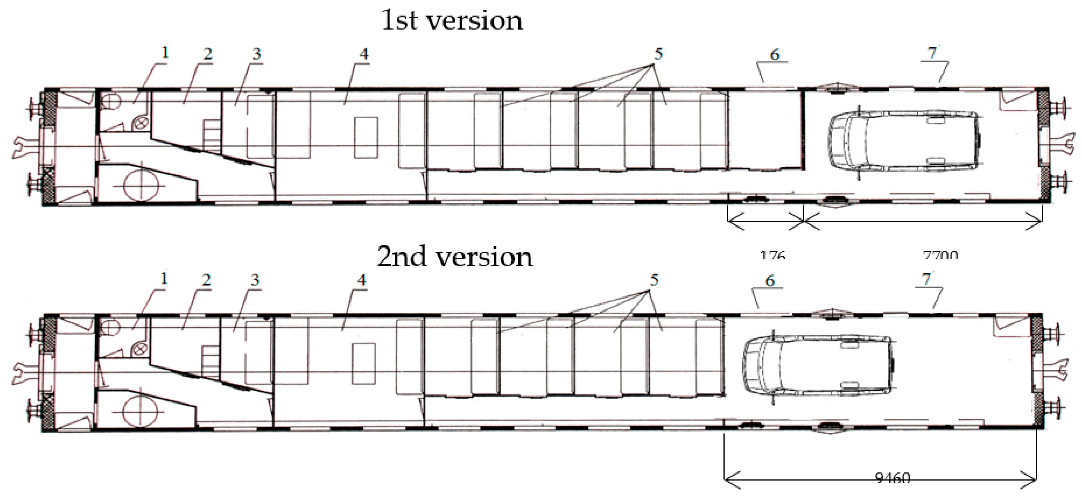
Figure 1. Scheme of installing a wagon in the back of a carriage.
Preprints 99152 g001
Figure 2. Three-dimensional model of the supporting structure of the wagon body.
Preprints 99152 g002
Figure 5. Equivalent stresses on the center and transverse beams: a) version 1; b) version 2.
Preprints 99152 g005
Figure 6. Natural frequencies of vertical vibrations of the body: а) version 1; b) version 2.
Preprints 99152 g006aPreprints 99152 g006b
Figure 7. Maximum values of vertical body accelerations: а) version 1; b) version 2.3. Results.
Preprints 99152 g007
Figure 12. Dependence of frame and guiding forces on the distance traveled in the curve.
Preprints 99152 g012
Figure 13. Dependence of frame forces on the distance traveled in the curve.
Preprints 99152 g013
Figure 14. Dependence of total forces on the distance traveled in the curve.
Preprints 99152 g014
Figure 20. Unsuppressed acceleration of the car body from passing a curved section of track.
Preprints 99152 g020
Figure 21. Wheelsets stability factor against derailment.
Preprints 99152 g021
Disclaimer/Publisher’s Note: The statements, opinions and data contained in all publications are solely those of the individual author(s) and contributor(s) and not of MDPI and/or the editor(s). MDPI and/or the editor(s) disclaim responsibility for any injury to people or property resulting from any ideas, methods, instructions or products referred to in the content.
Copyright: This open access article is published under a Creative Commons CC BY 4.0 license, which permit the free download, distribution, and reuse, provided that the author and preprint are cited in any reuse.
Prerpints.org logo

Preprints.org is a free preprint server supported by MDPI in Basel, Switzerland.

Subscribe

© 2024 MDPI (Basel, Switzerland) unless otherwise stated