1. Introduction
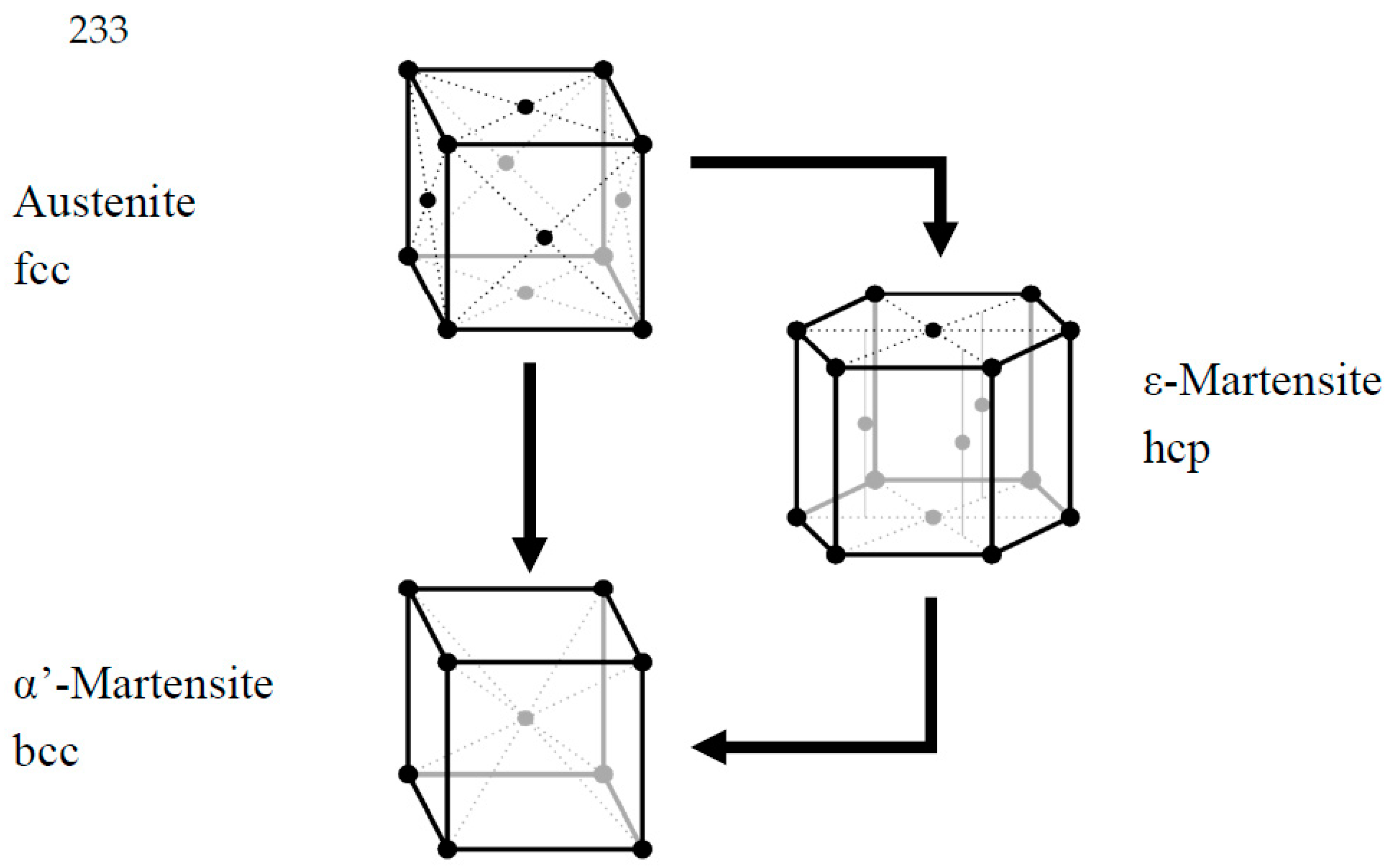
Due to the global economic and ecological change, the usage of innovative environmentally friendly and resource-saving technologies is in the focus of current research. In addition to the application of light metals, ultra-high-strength steel alloys and load-adapted components structures with improved material properties are increasingly being used. By adding alloying elements and targeted heat treatment, properties such as hardness, residual stresses, yield strength, tensile strength, elongation at break, toughness, fatigue strength, heat strength, machinability and corrosion resistance of the steel can be varied in many ways and adapted to the respective requirements. To manufacture highly resilient components, manufacturing processes of forming technology are often used. Besides densification sub surface compressive residual stresses can be achieved by forging processes. For example, in terms of achieving a beneficial sub surface structure forging processes had been in the focus also in the project tailored forming. Here a forging process is performed after a laser cladding or plasma welding process on bearings made of a AISI 52100 raceway on AISI 1022M structure material or martensitic chromium silicon steel (1.4718) on a base substrate of S235 (1.0038) steel [1, 2]. These forming processes could serve for an improved surface quality, the temperature had to be adjusted to enable an adequate forging process. The positive effects of residual compressive stresses on the service life in component areas subject to the highest rolling stresses have been known for a long time [3-5]. Previous studies could prove a beneficial effect of preinduced compressive residual stresses on bearing fatigue life for ALSI52100 bearings. These residual stresses were induced by deep rolling and turn-rolling [6-8]. In the present study the optimization of bearings made of stainless steel is in the focus. Such bearings are used for application in food industry, paper industry or for chemical processes as mass product [9]. But such bearings can be also found as high strength stainless steel bridge roller bearings [10]. Also, to withstand high temperature oxidation and corrosion aircraft bearings are made of stainless steels [11]. Thus, the idea is to achieve a beneficial residual stress state subsurface the bearing by improved forging processes. In this case a special focus must be set on a low temperature forging process. In general, forming at low temperatures, due to work hardening, sets higher material strengths in the component. During the forming of metastable austenitic steels, the resulting hardening is significantly increased by an additional deformation-induced martensitic phase transformation (see
Figure 1 on the left). The phase transformation is accompanied by the introduction of compressive stresses due to the increase in volume of the martensitic phase.
Martensitic Phase Transformation in Forging
In the cold forming of metastable austenitic steels, in addition to work hardening, an additional strength-enhancing phase transformation occurs, which is induced by externally introduced stresses and strains. Most stainless austenitic CrNi steels with approx. 18% Cr by mass and 10% Ni by mass are metastable austenitic in the non-deformed state. During forming, a partial conversion of the cubic face-centered (kfz) phase of the austenite into a cubic space-centered (krz) martensitic phase can take place [12]
The metastable austenitic stainless steels are mainly used in the chemical and food industries, e.g. for condensers, heat exchangers, coolers and pipelines. These are mainly sheet metal components. On the other hand, the effect of deformation-induced martensite formation in the field of solid forming has so far been little used industrially. These stainless steels are well known for applications for excavator bucket teeth and forklift tines, which harden due to mechanical loads in use.
Figure 1 shows the basic deformation-induced transformation process and the resulting solidification. The formed martensite consists of ferritic α’-martensite, which has a tetragonal-distorted fcc structure, and unstable ε-martensite with an hcp structure. This can be converted into α’-martensite (bcc) with further stress [13] The phase transformation from austenite to martensite caused by deformation is generally referred to as deformation-induced martensite formation.
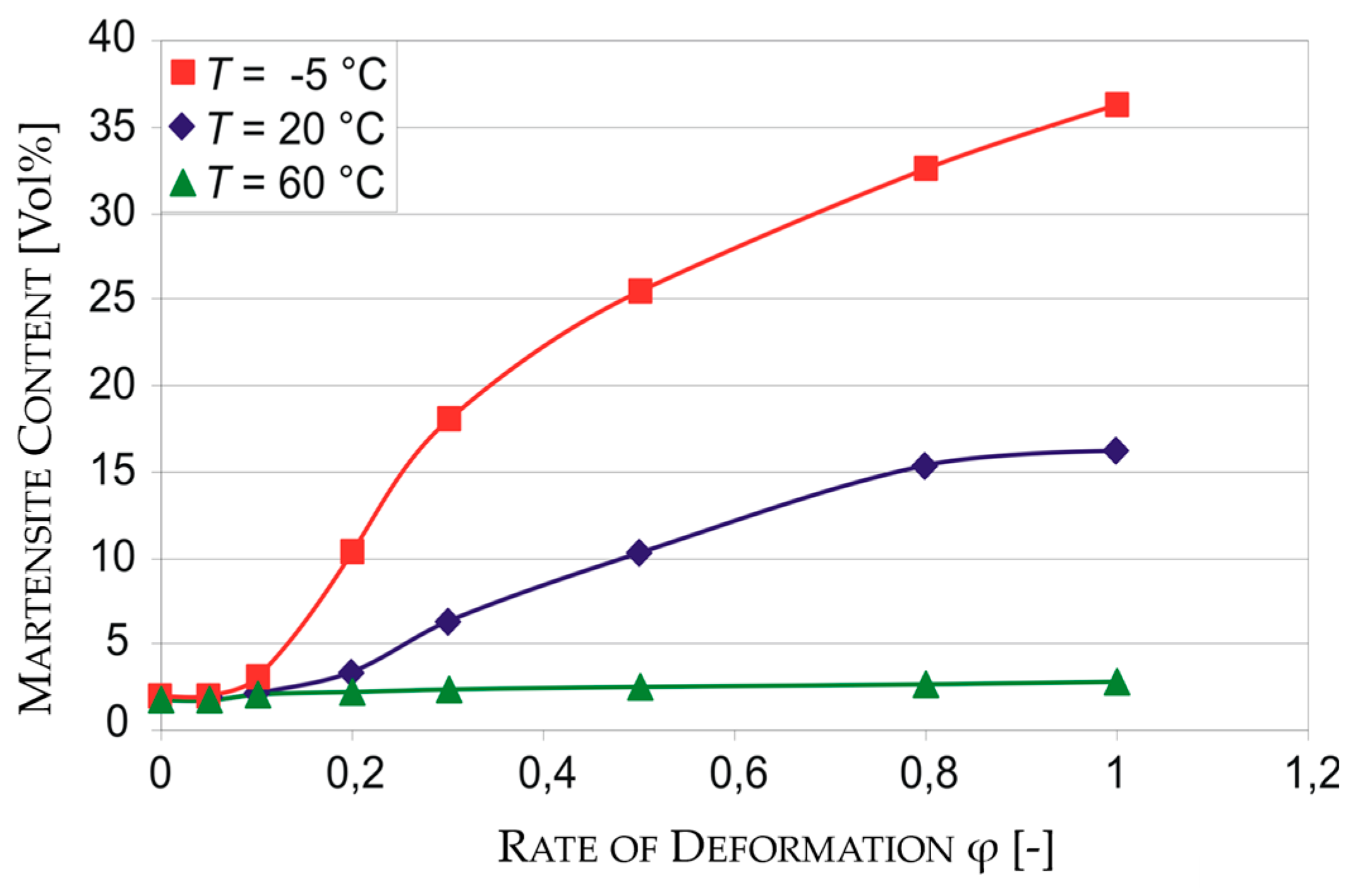
Furthermore, there is a dependence between the deformation-induced martensite formation and the forming temperature. By cooling the samples to T = -5 °C, an increase in the martensite content is possible compared to the experiments at room temperature. An increased forming temperature, on the other hand, reduces the effect of martensitic phase transformation (
Figure 2). At a temperature of T = 60 °C, martensite formation is almost completely suppressed. This temperature dependence has already been described by [15], among others.
The deformation-induced martensite formation and the associated expression of the yield stress of a metastable austenitic CrNi steel are complex mechanisms that are largely determined by alloy components and the parameters temperature as well as stress and strain state. There is a lot of research describing the fundamental effects of phase transformation in metastable austenitic steels [12,15,16]. Specifically, in the field of forging, only a few research papers are known in which the effect of deformation-induced phase transformation and its applications are investigated [17,18].
In the past, several doctoral theses have been written at the Bergakademie Freiberg, the subject of which is the occurrence of martensitic phases due to mechanical stress on the components close to the operation [19,20]. Currently, within the framework of the CRC 799 "TRIP-Matrix Composite", metastable austenitic CrMnNi steel casting materials with TRIP effect are being investigated [17].
At the University of Kaiserslautern, the influence of near-operational isothermal and thermal-mechanical stresses on the deformation behavior of metastable austenitic steels is investigated in the project "Influence of low temperatures on the cyclic deformation and transformation behavior of differently processed metastable austenites" as part of the Research Group "Engineering Materials on Different Scales: Experiment, Modelling and Simulation" [23].
Roller Bearings
Bearings enable a relative movement of machine parts and thus represent the concrete shape of joints in the sense of gear theory. Bearings take on both load-bearing and guiding tasks. The "carrying" function focuses on transmitting forces and moments between parts that are moving relative to each other. Depending on the direction of the forces to be transmitted, a distinction can be made between radial, axial and angular contact bearings. The "Guide" function determines the relative position of the parts that are moving relative to each other as precisely as possible. Non-locating bearings are used for guidance in the radial direction, fixed bearings additionally or exclusively for axial determination [23].
The relative motion between the active surfaces of a bearing can be sliding or drilling (tangential), rolling (radial) or rolling. Rolling is a combination of sliding and rolling motion. Sliding movements of solid-state surfaces in direct contact require a comparatively high amount of force and energy. At the same time, particles can detach, leading to surface wear during operation. This results in an essential requirement for a machine element: the function must be ensured or fulfilled for as long as possible. This means that destruction or progressive damage resulting in the eventual failure of the active surfaces or active bodies and an immediate or gradual change in the geometry with impairment of the guiding properties must be avoided or delayed for as long as possible. Typical mechanisms that can lead to functional impairment are breakage, plastic deformation, melting, seizure, fatigue, surface breakdown and wear [23].
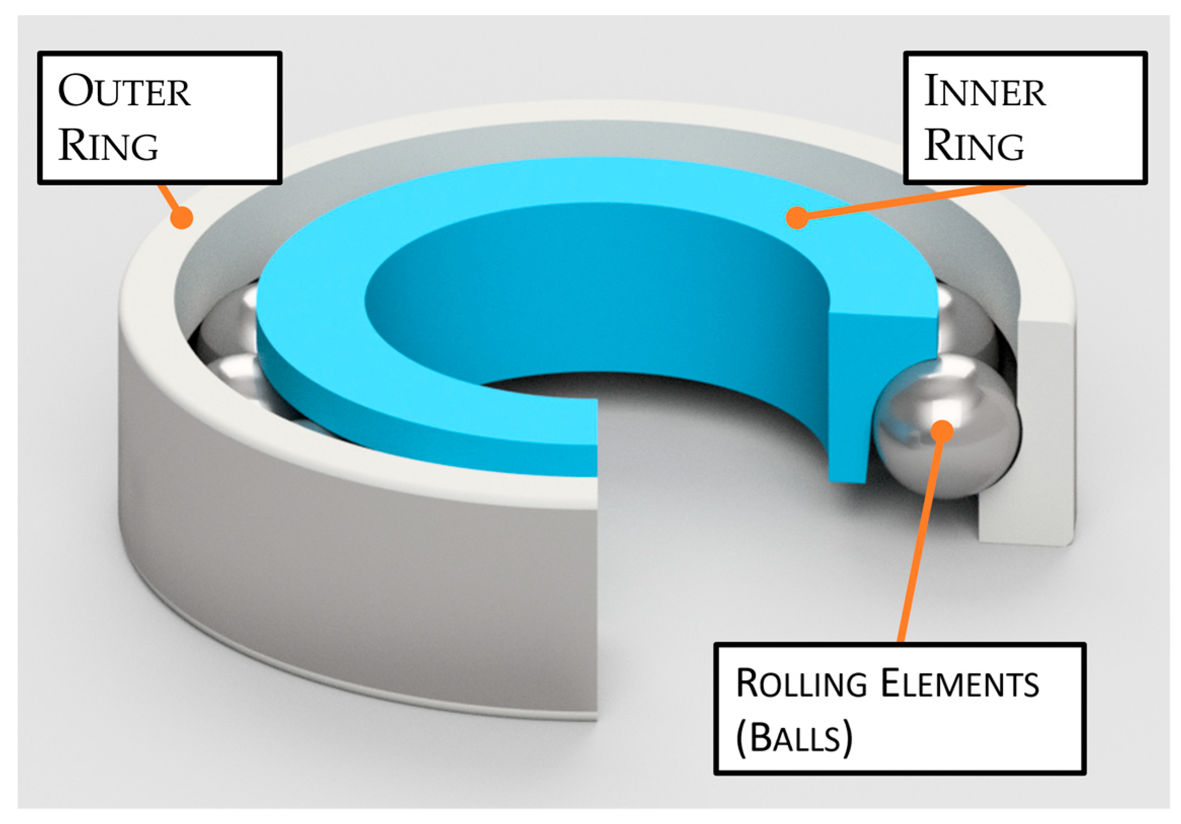
In addition to adhesive and abrasive wear in conjunction with tangential relative movements and friction under unfavorable operating and lubrication conditions, surface fatigue is a common cause of failure of rolling bearing systems. Increasing the reliability of rolling bearing assemblies by avoiding early failures as well as increasing bearing life are therefore the main concerns in the development of rolling bearings. As a result of improved bearing designs, they can not only achieve a longer bearing life, but can also be used in smaller, lighter and low-friction designs with the same service life. Kloos and Broszeit define surface fatigue as "the separation of microscopic and macroscopic material particles (…) caused by fatigue cracking, crack progression and residual fracture during the rolling of two force-bound surfaces (with and without slippage) under certain mechanical, thermal and chemical stress conditions" [24]. In contrast to wear, surface fatigue is a typical form of damage caused by material chipping instead of the removal of the material. Wear and surface fatigue are system properties of a component pairing, while general fatigue is a component property. In this work angular contact ball bearings were used, see
Figure 3. These bearings allow radial and axial loading, but in addition to rolling also experience spinning motion with additional tangential shear forces [25]. Most damages occur at the inner ring, as it is the part of a bearing that sees the highest loads. Therefore, the inner ring was the part that was manufactured with the aforementioned process. For the testing the inner ring (as seen in
Figure 3) was combined with a bought-in outer ring and balls.
2. Test Rig Development and Bearing Performance Tests
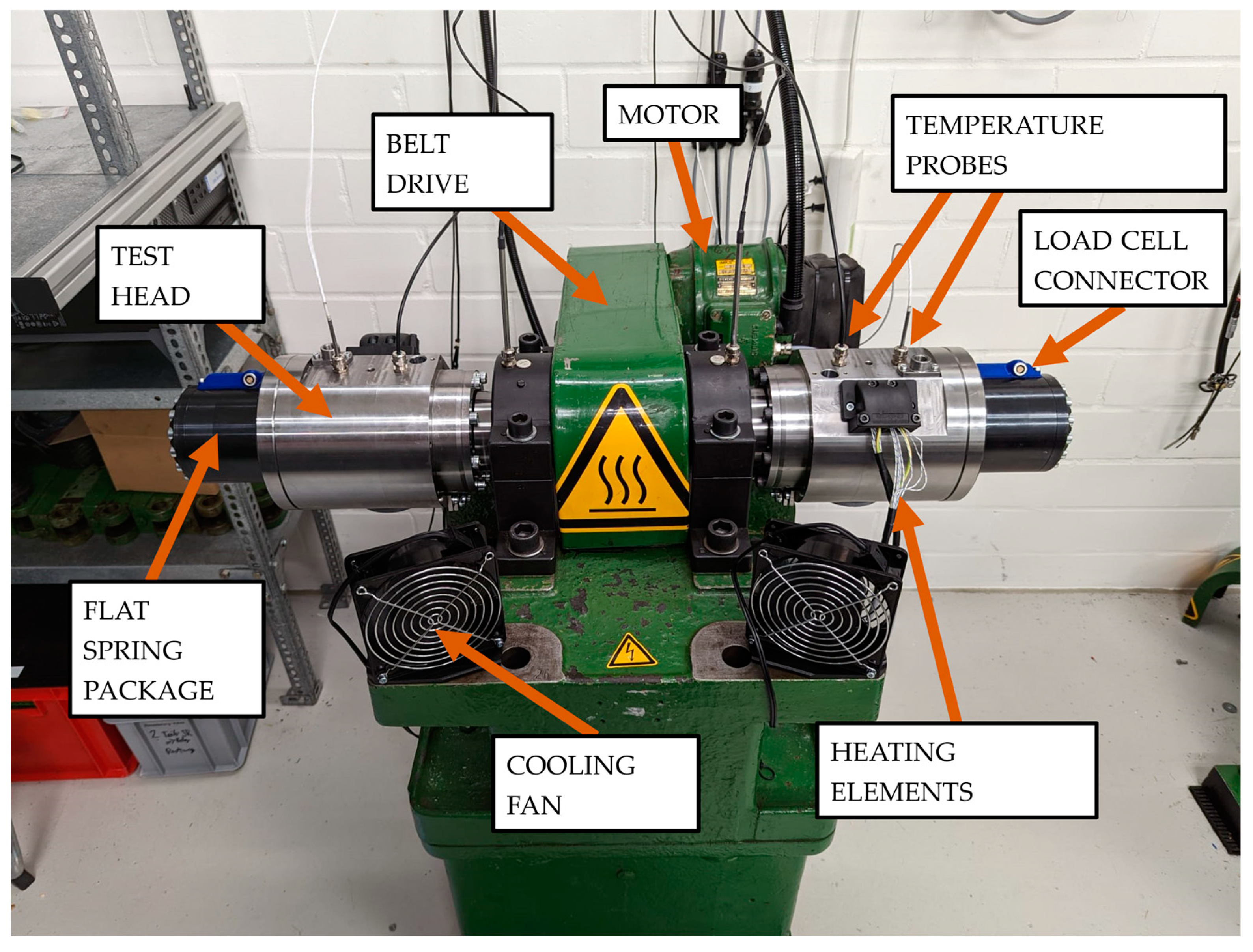
At the IMKT a novel test rig has been constructed on the foundational structure of a pre-existing SKF-manufactured machine designed for radial loading (as seen in
Figure 4). This upgraded test rig boasts the capability to concurrently test four bearings across two test heads. With a total of four machines featuring this configuration, a maximum capacity of testing up to 16 bearings simultaneously has been achieved. The two test heads are both connected to a central main shaft, interconnecting each unit’s secondary shaft via hydraulic couplings.
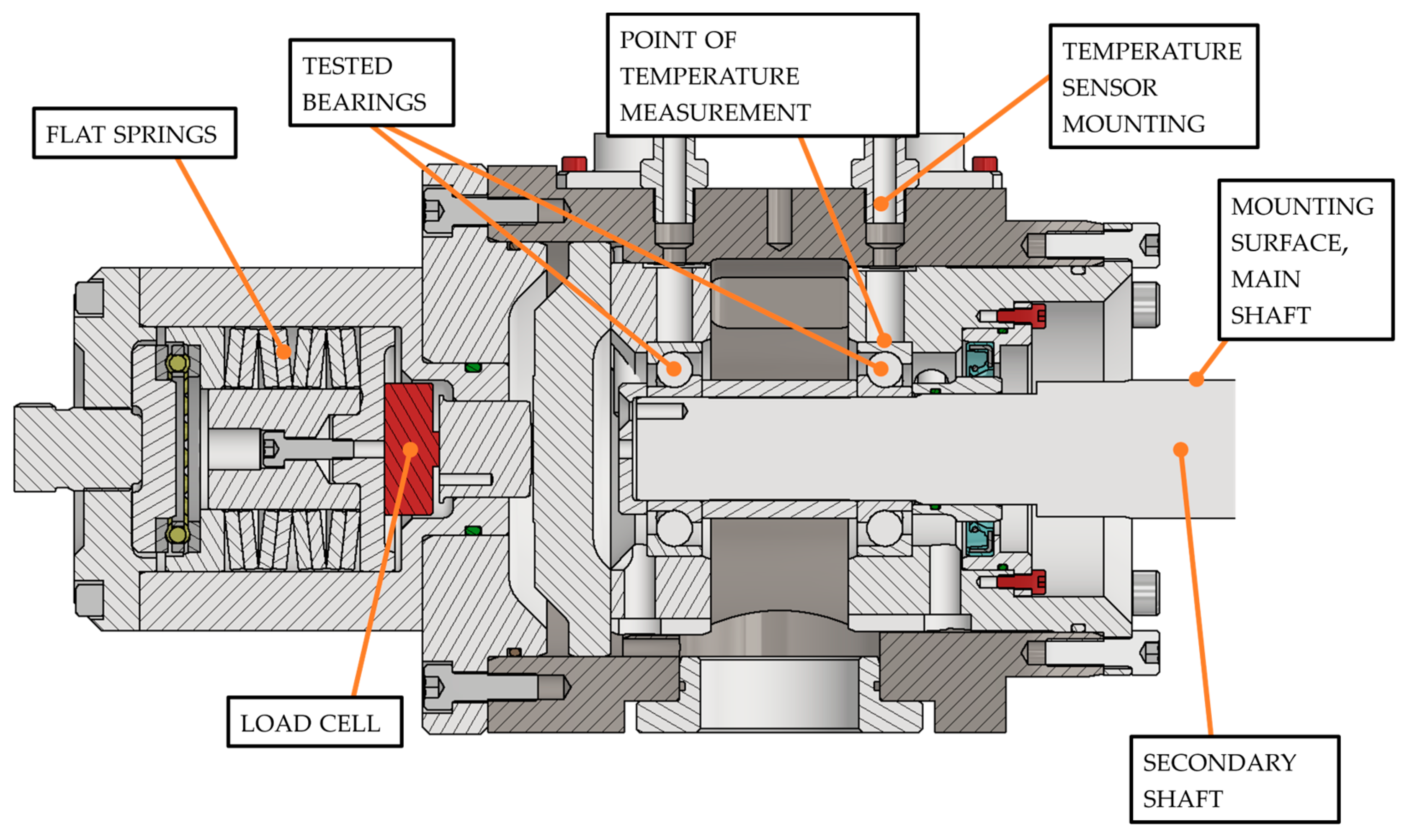
The support mechanism for the test heads involves radial suspension utilizing a rod, with provision for attachment of a force sensor to measure the Friction Torque exhibited by a pair of bearings. Furthermore, the axial load is applied through a set of flat springs situated on the outermost periphery of the test head. This applied force is monitored using a load sensor, ensuring precise control and measurement during testing procedures. A cross section of the test head is shown in
Figure 5.
Each individual bearing within this setup is equipped with a temperature sensor positioned on its outer ring, enabling monitoring of thermal variations. Regrettably, due to spatial constraints, the installation of a temperature sensor on the inner ring of the bearing was deemed impractical and therefore not implemented.
The implementation of a free-floating support system for the test head was chosen for its simplicity and capabilities in regard to the measurement of friction torque, constituting a pivotal advantage. However, this advantageous setup introduces its own set of challenges, primarily revolving around the need for precise alignment during the installation phase. The precise alignment of the secondary shafts within the hydraulic couplings has shown to be a critical factor, influencing especially the baseline vibrations recorded throughout the tests.
Moreover, the design decision for the free-floating support structure inherently subjects the bearings to radial loading, a factor demanding careful consideration. Evaluating the mass of the test head to approximately 38 kg, allows for an estimation of the radial loading exerted on each bearing, which can be conservatively estimated to reach 200N or below. While this magnitude of radial loading warrants attention, preliminary calculations suggest that its impact on the anticipated life expectancy of the bearings appears negligible, with no discernible substantial influence identified through initial assessments.
In addition to the measured friction torque and temperature values, the condition monitoring of the bearings in the test is ensured by a vibration sensor system attached to the front side of the test heads. With this, it is possible to detect any damage that forms in a timely manner.
Experimental Setup
When selecting the operating parameters for life expectancy tests, a critical consideration revolves around the distinctive properties of the utilized materials. Given the limited knowledge regarding the fatigue limits of bearings made from austenitic steels, a pragmatic approach was applied to derive the operational parameters. Consequently, an outlined solution was proposed to address this challenge. The initial step involved identifying the limit for a standard bearing possessing identical outer dimensions, readily accessible through manufacturers’ catalogs. A comparison of the material properties between bearing steel and austenitic steel revealed a notable reduction in the latter’s capabilities. In the literature the topic of bearing life for stainless-steel bearings has not seen a broad attention. So, for an initial estimate the technical manual of the bearing manufacturer has been taken, where it was proposed that a reduction to 80% of the load applied on a bearing of same dimensions, but made from standard bearing steel, has shown to be sufficient to ensure the stainless-steel bearings can endure a similar runtime under load.
Consequently, a reduction in load was implemented to achieve a comparable fatigue life using the following approach:
For the standard 7206 bearings, operating within a Hertzian Pressure limit of approximately 2.2 GPa and subjected to an axial load of 17500N, the maximum capacity of Stainless-Steel Bearings is conservatively estimated at 80% of that of the standard 100Cr6. Given the recognized lower hardness of 1.4301 in its austenitic state, a further reduction in the load by an additional 5% was undertaken. Therefore, the axial load for the series can be written as:
Another important point for the operating conditions is the height of the lubrication film and the state of lubrication. The parameter that has been considered is the Specific height of lubricating film
which can be calculated from the roughness of the two contacting surfaces and the calculated minimal film height.
However, it is important to add, that the measurement for the initial surface state of the Bought-in variants could only be determined on a small number of exemplary units. It was not possible to reliably disassemble the bearings without damaging them. Therefore, a small number of randomly chosen bearings were pulled from the test pool and investigated for their surface structure beforehand. As those numbers were showing a small deviation from each other, the then obtained values were taken as the initial state of all. An overview on the test parameters is given in
Table 1.
In the test cycle, the bearings were lubricated using a grease for high-speed applications. This specialized grease was selected to accommodate the relatively low load used in this test regimen. (DATA!!!).
Results
The bearings were investigated after manufacturing and compared to industrial stainless-steel bearings. Doing so, the surface of the manufactured bearings had to be machined after the forging process. In a next step the bearings were mounted into the test rig and fatigue tests were executed. In case of a surface failure or fatigue, the test was stopped. After the test the bearings surfaces were inspected in terms of microscopy.
Hardness
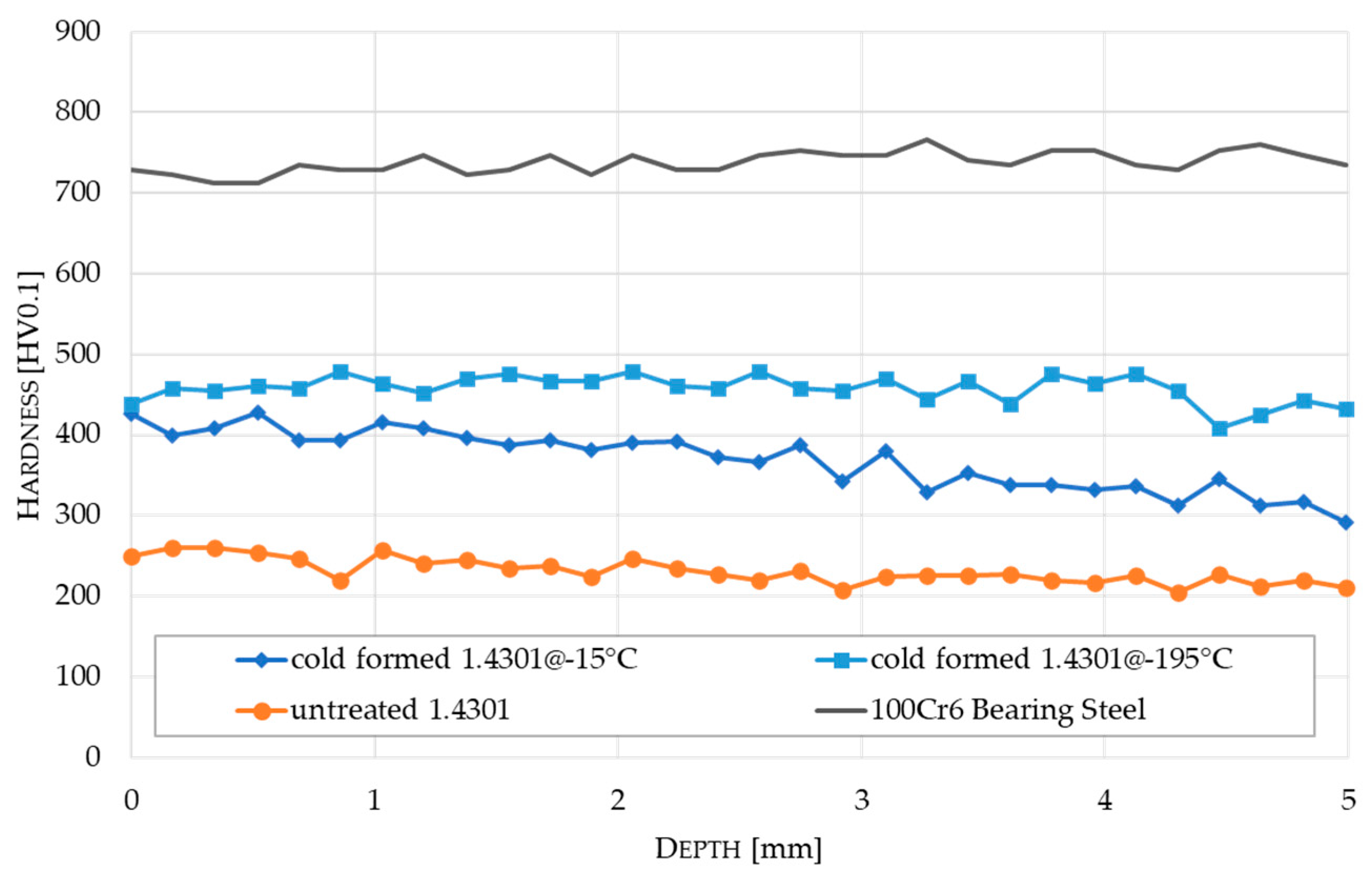
The assessment of a bearing surface’s hardness stands as a pivotal determinant in evaluating its suitability for bearing applications. Traditionally, standard bearing steel demonstrates exceptional hardness, often surpassing the 1000 HV0.1 threshold [Harris Bearing Steel???]. This elevated hardness level significantly outpaces the typical hardness achievable in various stainless-steel counterparts. The steel under scrutiny in this research exhibits a base hardness measuring around 250 HV0.1. However, through lowering of the forming temperature, a substantial enhancement in its hardness to approximately 500 HV0.1 has been achieved, as depicted in
Figure 6 and
Figure 7. For the investigations of the achievable hardness the forming process was performed at -15°C and -196°C. By reducing the temperature, a significant increase in surface hardness was achieved, which could be slightly improved for the lowest temperature. This increase in hardness presents an intriguing avenue for optimizing its performance and applicability in bearing scenarios, underscoring the pivotal role of temperature modulation in altering the material’s mechanical properties for enhanced functionality.
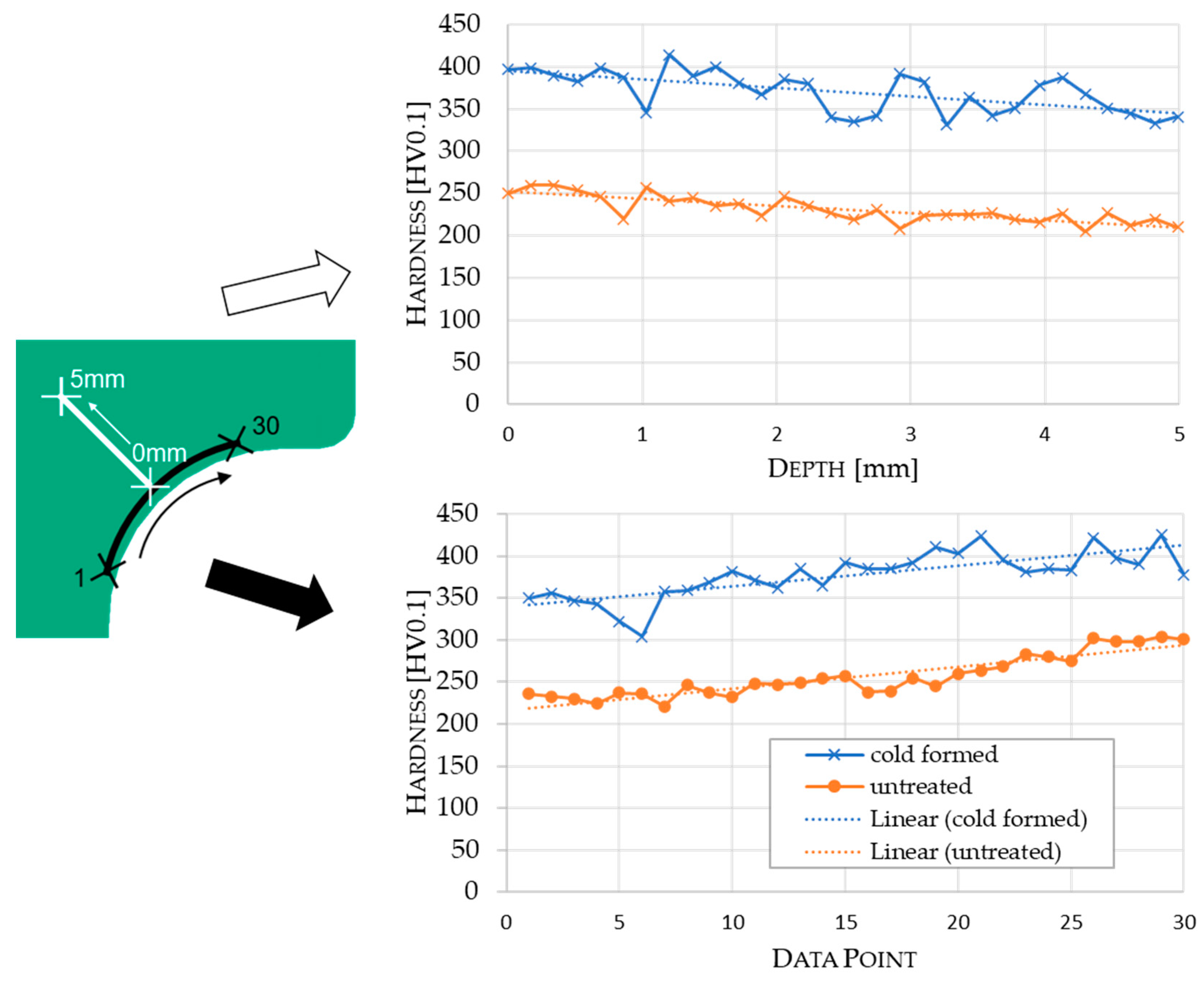
The Hardness has been measured in two different directions on the different samples. Both are defined on the run zone. The depth direction starts in the middle of the run zone and follows the angle of contact of the bearing, which per design is 40 degrees. The second direction follows the contour of the raceway outwards. With the beginning and the end approximately 1mm outside of the run zone.
Figure 6 shows that the hardness declines slightly more in the depth of the tested cold formed specimen compared to the unaltered sample. In comparison to the untreated sample, significantly greater variations in hardness levels are evident in both dimensions. This is likely attributed to the lack of homogeneity in the crystal lattice due to the produced martensite. Along the running zone, the trends in both samples are very similar. Additionally, besides the noticeably increased hardness, a more pronounced deviation from the mean is discernible compared to the initial material.
Roughness
The surface roughness has a strong impact on bearing life regarding mechanical performance and longevity. Surface roughness directly affects the tribological interactions within a bearing system, governing the contact between rolling elements and races. Excessive roughness can intensify abrasive wear, generating elevated frictional forces and accelerating material fatigue. On the contrary, an excessively smooth surface might compromise the formation of crucial lubricating films, leading to inadequate separation between contacting surfaces and heightened risk of adhesive wear. The Roughness of the contacting surfaces impacts load distribution, fatigue resistance, and overall operational reliability of bearings, thereby directly influencing their expected lifespan and performance under operational conditions.
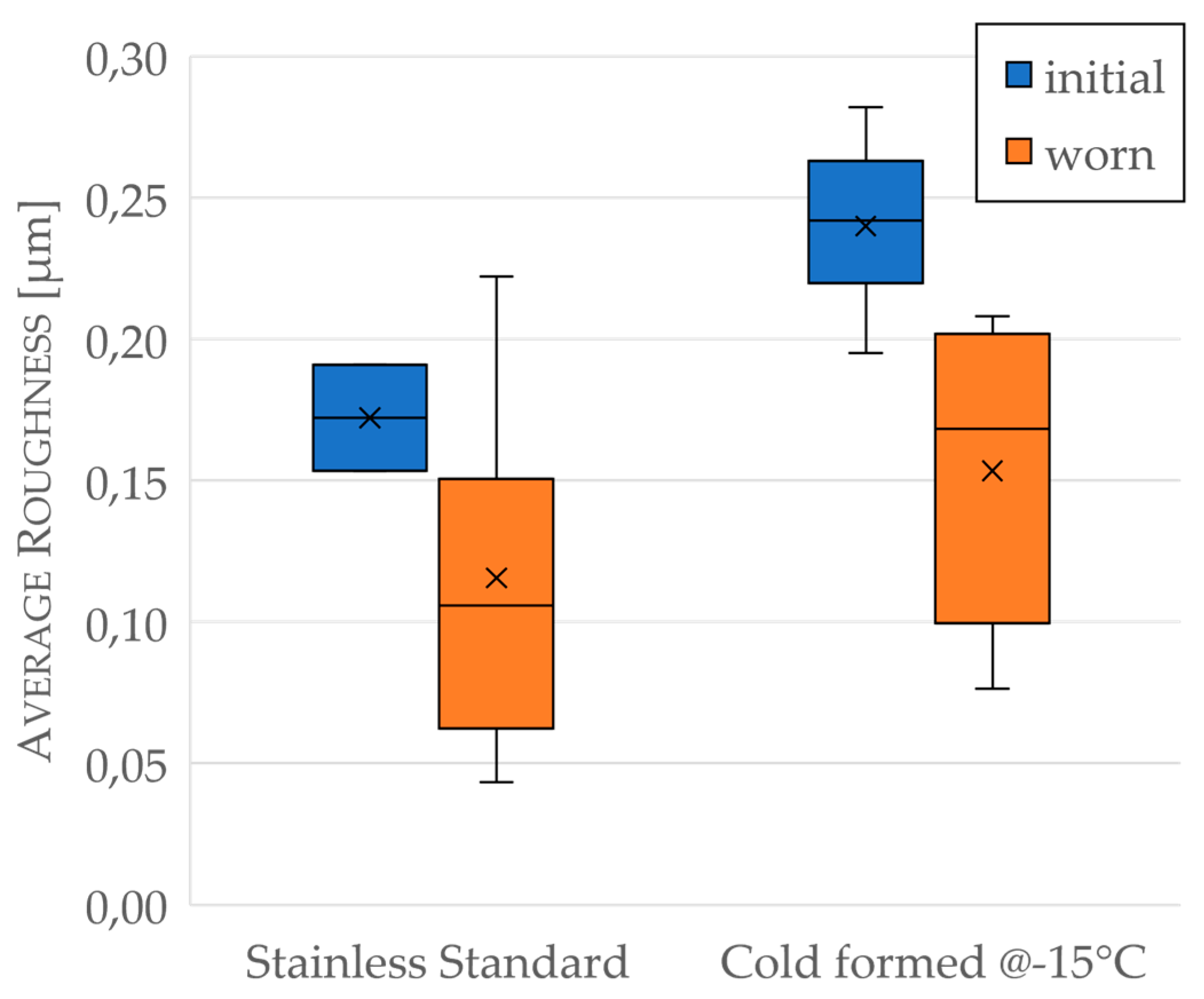
The preliminary examination of surface characteristics, considering the previously outlined limitations, reveals that the cold-formed bearings exhibit a marginally rougher surface compared to the standard bearings (see
Figure 8). For the standard bearings, the average post-test surface roughness is notably lower. However, it is crucial to note that the deviation in roughness is higher for the standard bearings. Both sets of bearings undergo a process of surface smoothening after testing, with the cold-formed bearings displaying a more pronounced effect. An important observation is that the initial state of the cold-formed bearings tends to be slightly rougher, attributable to the manufacturing process. In contrast, the standard bearings commence with a comparatively smoother initial surface.
Test Evaluation
Table 2 shows the results from a series of eight tests conducted on bearings subjected to 13kN axial loading at 2000rpm, while none ran more than 46 million cycles. The observed outcomes varied. Most tests saw noticeable signs of wear (V). Some showed extended pitting damage (P), characterized by broken up surfaces and signs of fracturing running along the sides of the pitting, as seen in figure X, right hand side. Three bearings showed a form of adhesive damage (A), characterized by a grey surface often accompanied by smaller pittings. Three bearings showed signs of overheating (H), especially characterized by dark discolored raceways. The tests were mostly terminated by the condition monitoring system, watching over the vibrations (S). Two were ended by breaching the temperature limit (T). One of those tests was most probably not sufficiently lubricated and therefore taken out of consideration (not Counted).
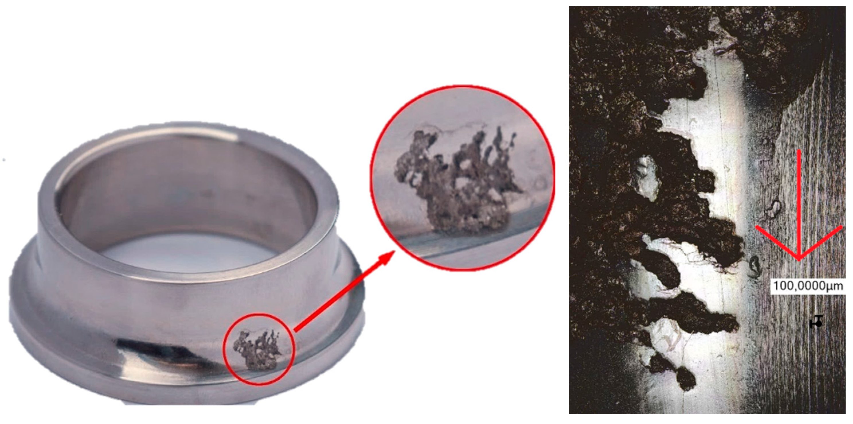
An microscopic image of an industrial stainless steel bearing after test is shown in
Figure 9, the bearing run for over 250 hours, the test stopped due to bearing damage. In the visual examination of the worn stainless-steel bearing, distinct characteristics indicative of prolonged use and stress concentrations are apparent. Notably, the run-zone exhibits a considerable darkening, suggesting heightened frictional forces and localized heating during operation. Concurrently, a number of small pitting manifest prominently within the region experiencing the highest pressure. These discernible pits underscore the consequential effects of repetitive loading, potentially indicating surface fatigue and material degradation in response to the intense mechanical stresses endured by the bearing during its operational lifecycle.
The results from the series of cold formed bearings can be seen in
Table 3. Overall, there were 10 tests conducted with two bearings per test. The conditions regarding speed, load, temperature and lubrication were the same as in the previous series. One set was retracted in the early stages of the testing and could not be tested again. This was due to a sensor error which led to us being unable to determine the faulty bearing on this particular test rig. As the conditions may be altered by the mounting process, we decided to retract both sets of bearings, although one set was unharmed (tests 3+4). One set was later damaged during the mounting process and was never used.
As in the previous array of tests the most common observation were signs of wear (V). The occurrence of overheated surfaces (H) was less common and also in the two Instances that showed discoloring, less pronounced. On the other hand, the fatigue damage occurrences had a much larger affected area than on the standard bearings. This could be a sign for a faster rupture of the surface layers, as the detection method was the same. Therefore, a newly formed pitting would be growing slower on the standard bearing surface than in the cold formed bearings. This could be due to the formation of martensite being sometimes inhomogeneous. Which could then lead to larger pieces breaking out of the surface in case a sufficient crack is formed under the surface.
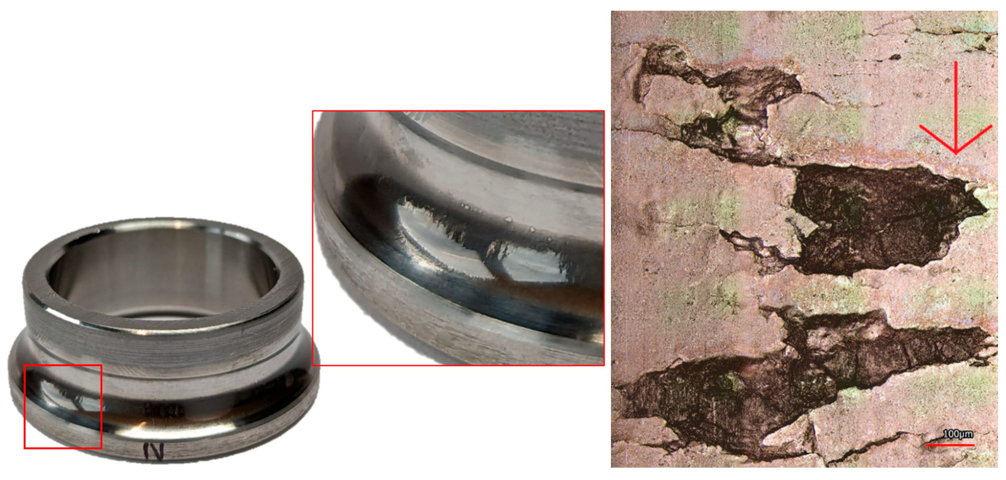
The picture above shows a cold-formed stainless steel bearing inner ring after a test of only 0.72 million cycles (
Figure 10). The bearing shows a large pitting defect, spanning the entire width of the contact zone, with nearly the same length in the circumferential direction. Furthermore, an additional facet of the visual assessment reveals a polished character in the contact area, due to wear, which is often observed in these bearings.
Bearing Life
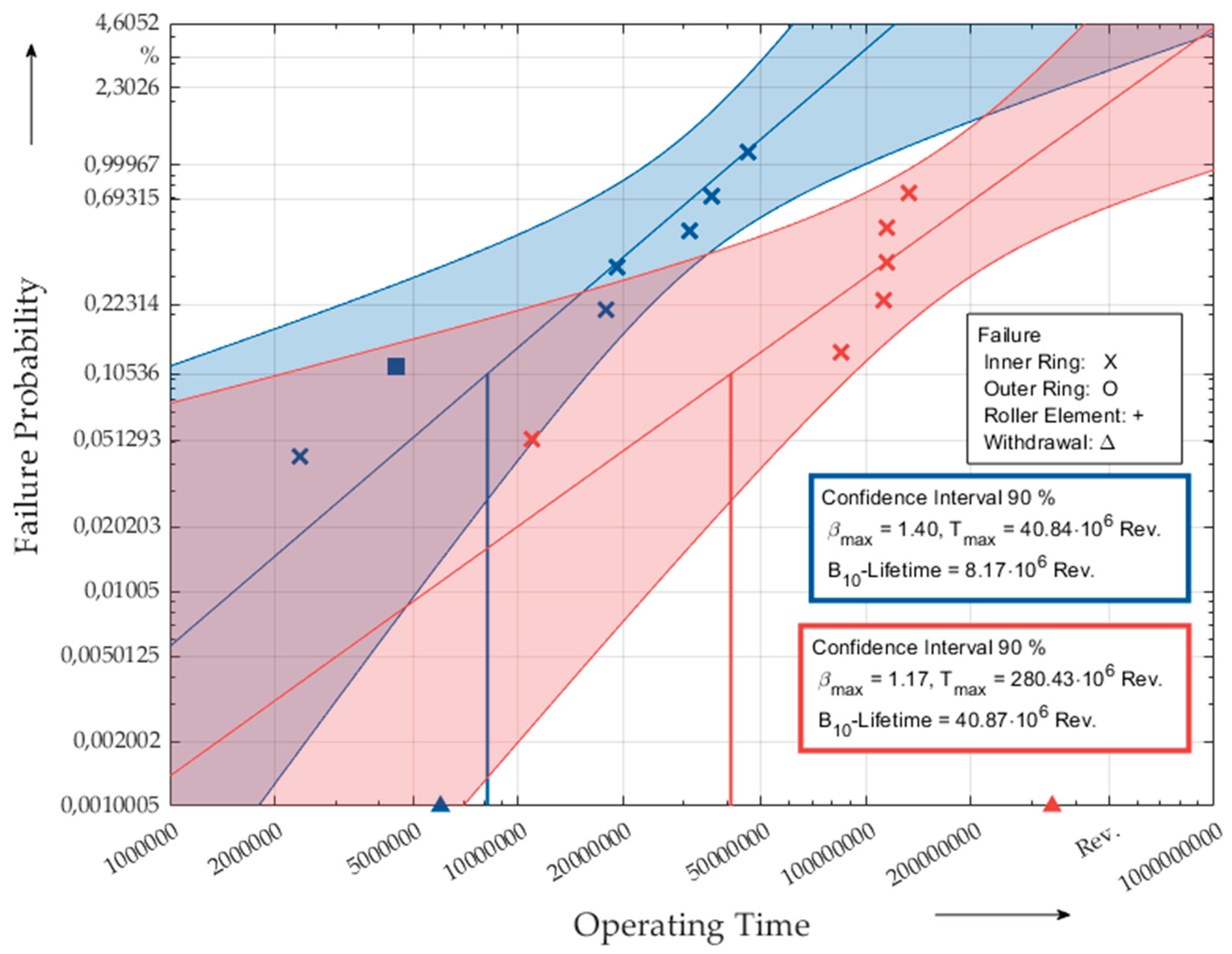
We can show that the process significantly improves bearing life. A direct comparison of industrial stainless-steel bearings and the manufactured bearings is shown in the Weibull plot (
Figure 11). By the beneficial martensitic surface with increased hardness the bearing fatigue could be increased by a factor of approx. 4. This features a significant effect and allows for improved machine elements. The results prove also, that due to the highest loads on the bearings inner ring, only this part suffers fatigue and is the critical part.
Conclusion
Stainless steel bearings often serve as essential components within machinery. However, their current state is often subjected to fatigue due to a comparatively small surface hardness. Addressing this concern, the proposed method aimed at enhancing the surface integrity of stainless-steel bearings through a low-temperature forging technique demonstrates a significant augmentation in bearing fatigue life. This enhancement stems from the creation of a martensitic subsurface layer characterized by increased surface hardness.
An essential consequence of this process involves the induction of beneficial residual stresses attributed to martensite formation. While the forging process poses considerable challenges, particularly concerning radial bearings, its application to axial bearings proves relatively straightforward. This simplicity not only fosters improved machine elements but also enables the construction of more compact, resource-efficient facilities.
Consequently, future studies will center on the low temperature forging of axial bearing washers to induce a martensitic subsurface, thereby potentially replicating the success witnessed in other bearing components. The integration of such a forging technique into bearing fabrication appears relatively seamless. Despite the incremental energy expenditure for cooling during this process, it is substantially offset by the substantial increase in bearing fatigue life—a trade-off that amplifies the overall longevity and reliability of these critical machine components.
Acknowledgements
The authors like to thank the DFG, German Research Foundation, for the financial support of the project 423160066 - Surface layer treatment using martensite formation of formed stainless steel.
References
- Coors, T., Mildebrath, M., Büdenbender, C., Saure, F., Faqiri, M. Y., Kahra, C., … & Poll, G. Investigations on tailored forming of AISI 52100 as rolling bearing raceway. Metals 2020, 10, 1363. [CrossRef]
- Pape, F., Coors, T., Barroi, A., Hermsdorf, J., Mildebrath, M., Hassel, T., … & Poll, G. Tribological study on tailored-formed axial bearing washers. Tribol. Online 2018, 13, 320–326. [CrossRef]
- Voskamp, A. P., & Mittemeijer, E. J. State of residual stress induced by cyclic rolling contact loading. Mater. Sci. Technol. 1997, 13, 430–438. [CrossRef]
- Voskamp, A. P. Ermüdung und Werkstoffverhalten im Wälzkontakt. HTM Journal of Heat Treatment and Materials, 1998, 53, 25-30. [CrossRef]
- Voskamp, A. P. Microstructural stability and bearing performance. In Bearing Steel Technology. ASTM International. 2002. [CrossRef]
- Pape, F., Coors, T., & Poll, G. Studies on the influence of residual stresses on the fatigue life of rolling bearings in dependence on the production processes. Front. Mech. Eng. 2020, 6, 56. [CrossRef]
- Denkena, B., Poll, G., Maiß, O., Pape, F., & Neubauer, T. Enhanced boundary zone rolling contact fatigue strength through hybrid machining by hard turn-rolling. Bear. World J. 2016, 1, 87–102.
- Coors, T., Pape, F., & Poll, G. Bearing fatigue life of a multi-material shaft with an integrated raceway. Bear. World J. 2018, 3, 23–30. [CrossRef]
- Bhadeshia, H. K. D. H. Steels for bearings. Prog. Mater. Sci. 2012, 57, 268-435. [CrossRef]
- Noury, P., & Eriksson, K. Failures of high strength stainless steel bridge roller bearings: A review. Eng. Fract. Mech. 2017, 180, 315-329. [CrossRef]
- Chen, H., Zeng, T., Shi, Q., Wang, N., Zhang, S., Yang, K., … & Wang, W. Microstructure Evolution and Mechanical Properties during Long-term Tempering of a Low Carbon Martensitic Stainless Bearing Steel. J. Mater. Res. Technol. 2023. [CrossRef]
- Schmidt, W.; Küppers, W.: Der Einfluß der Austenit-Stabilität auf mechanische Eigenschaften und Umformverhalten von Chrom-Nickel-Stählen, Thyssen Edelstahl, Technische Berichte 12, Band 1986, Heft 1, S. 80-100, 1986.
- Barenbrock, D.: Einfluss verformungsinduzierter Martensitumwandlung auf das Rissfortschrittsverhalten austenitischer Stähle, Dissertation, Universität Hannover, 2002.
- Lindenberg, H.-U.; Kazmierski O.; Otto, A.: Kaltgewalztes Band aus nichtrostenden Edelstählen und die Anwendungspotentiale, Stahl und Eisen, Heft 5, S. 37-42, 2000.
- Olsen, G. B.; Cohen, M.: Kinetics of strain induced martensite nucleation, Metall, Trans 6A, 1975. [CrossRef]
- Schmitz, K. W.: Beitrag zum Tiefziehen von unterschiedlich stabil austenitischen Werkstoffen bei gezielter Temperaturführung, Dissertation, TU Clausthal, 1974.
- Biermann, H. & Aneziris, Christos. Austenitic TRIP/TWIP Steels and Steel-Zirconia Composites Design of Tough, Transformation-Strengthened Composites and Structures: Design of Tough, Transformation-Strengthened Composites and Structures. 2020. [CrossRef]
- Henschel, Sebastian & Posselt, F. & Dudczig, Steffen & Wetzig, Tony & Aneziris, C.G. & Krüger, Lutz. Experimental determination of toughness under mode I/II loading. Procedia Struct. Integr. 2020, 28, 1369-1377. [CrossRef]
- Onyuna, M. O.: Deformation Behaviour and Martensitic Transformations in Metastable Austenitic Steels and Low Alloyed Multiphase Steels, Dissertation, Bergakademie Freiberg, 2003.
- Schoß, V. Martensitische Umwandlung und Ermüdung austenitischer Edelstähle, Gefügeveränderungen und Möglichkeiten der Früherkennung von Ermüdungs-schädigungen, Dissertation, Bergakademie Freiberg, 2001.
- Oettel, Heinrich and Martin, Ulrich. The nature of the TRIP-effect in metastable austenitic steels: Dedicated to Professor Eckard Macherauch on the occasion of the 80th anniversary of his birth. Int. J. Mater. Res. 2006, 97, 1642-1647. [CrossRef]
- Beck, T., Smaga, M., Influence of the Surface State on Quasi-static and Cyclic Deformation and Damage Behavior of TRIP/TWIP Steels (B10), DFG-Project 172116086. https://gepris.dfg.de/gepris/projekt/278735173.
- Steinhilper, W.; Sauer, B.: Konstruktionselemente des Maschinenbaus 2, Grundlagen von Maschinenelementen für Antriebsaufgaben, 6. Auflage, Springer-Verlag, Berlin, Heidelberg, 2008.
- Kloos, K. H.; Broszeit, E.: Grundsätzliche Betrachtungen zur Oberflächenermüdung, Werkstofftechnik 3 (1976), S. 85-96.
- Pape, F., Coors, T., Wang, Y., & Poll, G. (2019). Fatigue life calculation of load-adapted hybrid angular contact ball bearings. In Proceedings of the 7th International Conference on Fracture Fatigue and Wear: FFW 2018, 9-10 July 2018, Ghent University, Belgium (pp. 401-414). Springer Singapore. [CrossRef]
|
Disclaimer/Publisher’s Note: The statements, opinions and data contained in all publications are solely those of the individual author(s) and contributor(s) and not of MDPI and/or the editor(s). MDPI and/or the editor(s) disclaim responsibility for any injury to people or property resulting from any ideas, methods, instructions or products referred to in the content. |
© 2024 by the authors. Licensee MDPI, Basel, Switzerland. This article is an open access article distributed under the terms and conditions of the Creative Commons Attribution (CC BY) license (http://creativecommons.org/licenses/by/4.0/).
