Submitted:
19 February 2024
Posted:
22 February 2024
You are already at the latest version
Abstract
Keywords:
1. Introduction
2. Materials and Methods
2.1. The basics of Simulink model
2.2. Model of indirect rotor flux orientation
2.3. PID and PID fuzzy controllers
3. Simulation results of system with PID and PID fuzzy controllers
3.1. Simulation results system with PID controller
3.1.1. Step response of system with PID controller
3.1.2. Simulation results of system with PID controller and provided reference speed
3.2. Simulation results with PID fuzzy controller
3.2.1. Step response of system with PID fuzzy controller
3.2.2. Simulation results of system with PID fuzzy controller and provided reference speed
4. Discussion
5. Conclusions
Author Contributions
Conflicts of Interest
References
- Levi, E. “Multiphase electric machines for variable-speed applications,” IEEE Transactions on Industrial Electronics, vol. 55, no. 5, pp. 1893–1909, May 2008. [CrossRef]
- Brazhnikov, V.; Belozerov, I.R. “Prospects for the use of Multiphase Inverter-fed Asynchronous Drives in the Field of Traction Systems of Railway Vehicles,” International Journal of Railway, vol. 5, no. 1, pp. 38–47, 2012. [CrossRef]
- Bugade, V. “Multiphase Induction Motor Drive for Energy and Electrical Transportation Applications,” Int J Res Appl Sci Eng Technol, vol. 6, no. 4, pp. 166–174, Apr. 2018. [CrossRef]
- Akpama E.J. “Six Phase Induction Motor Modelling for Submarine Application,” vol. 13, no. 1, pp. 61–66, 2018. [CrossRef]
- Abdelwanis,M.I.; Selim, F.“A sensorless six-phase induction motor driving a centrifugal pump system,” 2017 19th International Middle-East Power Systems Conference, MEPCON 2017 - Proceedings, vol. 2018-Febru, no. December, pp. 242–247, 2018. [CrossRef]
- Rao, Y.L.N. “A novel electric vehicle control - electronic differential - strategy using five phase induction motor,” vol. 032, no. 1, pp. 153–159, 2018.
- Salem and M. Narimani, “A Review on Multiphase Drives for Automotive Traction Applications,” IEEE Transactions on Transportation Electrification, vol. 5(4), 1329, 2019. [CrossRef]
- J. Listwan and P. Oleszczyszyn, “Analysis of the Drive of the Electric Vehicle with Six-Phase Induction Motor,” Power Electronics and Drives, vol. 8, no. 1, 2023. [CrossRef]
- W. Cao, B. C. Mecrow, G. J. Atkinson, J. W. Bennett, and D. J. Atkinson, “Overview of electric motor technologies used for more electric aircraft (MEA),” IEEE Transactions on Industrial Electronics, vol. 59, no. 9, pp. 3523–3531, 2012. [CrossRef]
- J. Xie, W. Shi, and Y. Shi, “Research on Fault Diagnosis of Six-Phase Propulsion Motor Drive Inverter for Marine Electric Propulsion System Based on Res-BiLSTM,” Machines, vol. 10, no. 9, 2022. [CrossRef]
- H. Mesai-Ahmed, I. Jlassi, A. J. Marques Cardoso, and A. Bentaallah, “Multiple Open-Circuit Faults Diagnosis in Six-Phase Induction Motor Drives Using Stator Current Analysis,” IEEE Trans Power Electron, vol. 37, no. 6, 2022. [CrossRef]
- H. R. P. Antunes, D. S. B. Fonseca, and A. J. M. Cardoso, “Modeling of Symmetrical Six-Phase Induction Machines Under Stator Faults,” IEEE Trans Ind Appl, vol. 59, no. 3, 2023. [CrossRef]
- G. K. Singh and A. Iqbal, “Modeling and analysis of six-phase synchronous motor under fault condition,” Chinese Journal of Electrical Engineering, vol. 3, no. 2, 2017. [CrossRef]
- E. Levi, R. Bojoi, F. Profumo, H. Toliyat, and S. Williamson, “Levi, E., et al. "Multiphase induction motor drives–a technology status review,” IET Electr Power Appl, 2007. [CrossRef]
- S. Mandal, “Performance Analysis of Six-Phase Induction Motor,” vol. 4, no. 02, pp. 589–593, 2015.
- H. P. Nabi, P. Dadashi, and A. Shoulaie, “A novel structure for vector control of a symmetrical six-phase induction machine with three current sensors,” 2011 10th International Conference on Environment and Electrical Engineering, EEEIC.EU 2011 - Conference Proceedings, vol. 1, pp. 23–29, 2011. [CrossRef]
- K. S. Aher and A. G. Thosar, “Modeling and Simulation of Five Phase Induction Motor using MATLAB / Simulink,” vol. 6, no. 5, pp. 1–8, 2016.
- R. Gregor, F. Barrero, S. Toral, and M. J. Durán, “Realization of an asynchronous six-phase induction motor drive test-rig,” Renewable Energy and Power Quality Journal, vol. 1, no. 6, pp. 101–105, 2008. [CrossRef]
- Y. Zhao and E. G. Collins, “Fuzzy PI control design for an industrial weigh belt feeder,” IEEE Transactions on Fuzzy Systems, vol. 11, no. 3, pp. 311–319, 2003. [CrossRef]
- G. Renukadevi and K. Rajambal, “Generalized model of multi-phase induction motor drive using matlab/simulink,” in 2011 IEEE PES International Conference on Innovative Smart Grid Technologies-India, ISGT India 2011, 2011, pp. 114–119. [CrossRef]
- P. Venter, A. A. Jimoh, and J. L. Munda, “Realization of a ‘3 & 6 phase’ induction machine,” Proceedings - 2012 20th International Conference on Electrical Machines, ICEM 2012, no. January, pp. 447–453, 2012. [CrossRef]
- E. J. Akpama and L. U. Anih, “Modelling and Simulation of Multiphase Induction Machine,” International Journal of Engineering Innovation & Research, vol. 4, no. 5, pp. 2277–5668, 2015.
- S. N. Vukosavic, M. Jones, E. Levi, and J. Varga, “Rotor flux-oriented control of a symmetrical six-phase induction machine,” Electric Power Systems Research, vol. 75, no. 2–3, pp. 142–152, 2005. [CrossRef]
- R. Rinkevičicne, B. Mitkienė, and D. Udris, “Modelling and Comparison PID Fuzzy Controllers for Six-phase Drive,” in 2023 IEEE Open Conference of Electrical, Electronic and Information Sciences (eStream), Vilnius: IEEE, Apr. 2023, pp. 1–5. [CrossRef]
- R. Rinkeviciene, B. Mitkiene, and D. Udris, “Modelling of Six-Phase Electric Drive with PI and PD Fuzzy Controllers,” 2021 IEEE Open Conference of Electrical, Electronic and Information Sciences, eStream 2021 - Proceedings,.
- R. Rinkeviciene, B. Mitkiene, and D. Udris, “Design and Comparison of Fuzzy Controllers for Six-phase Drive,” 2020 IEEE Open Conference of Electrical, Electronic and Information Sciences, eStream 2020 - Proceedings, pp. 1–5, 2020. [CrossRef]
- G. K. Singh, “Multi-phase induction machine drive research - A survey,” Electric Power Systems Research, vol. 61, no. 2, pp. 139–147, Mar. 2002. [CrossRef]
- Kundrotas, S. Lisauskas, and R. Rinkeviciene, “Model of multiphase induction motor,” Elektronika ir Elektrotechnika, 2011. [CrossRef]
- K. M. Passino and S. Yurkovich, “Fuzzy control,” in The Control Systems Handbook: Control System Advanced Methods, Second Edition, 2010. [CrossRef]
- Bose B.K., Modern power engineering and electric drives. 2002. Prentice Hall PTR.




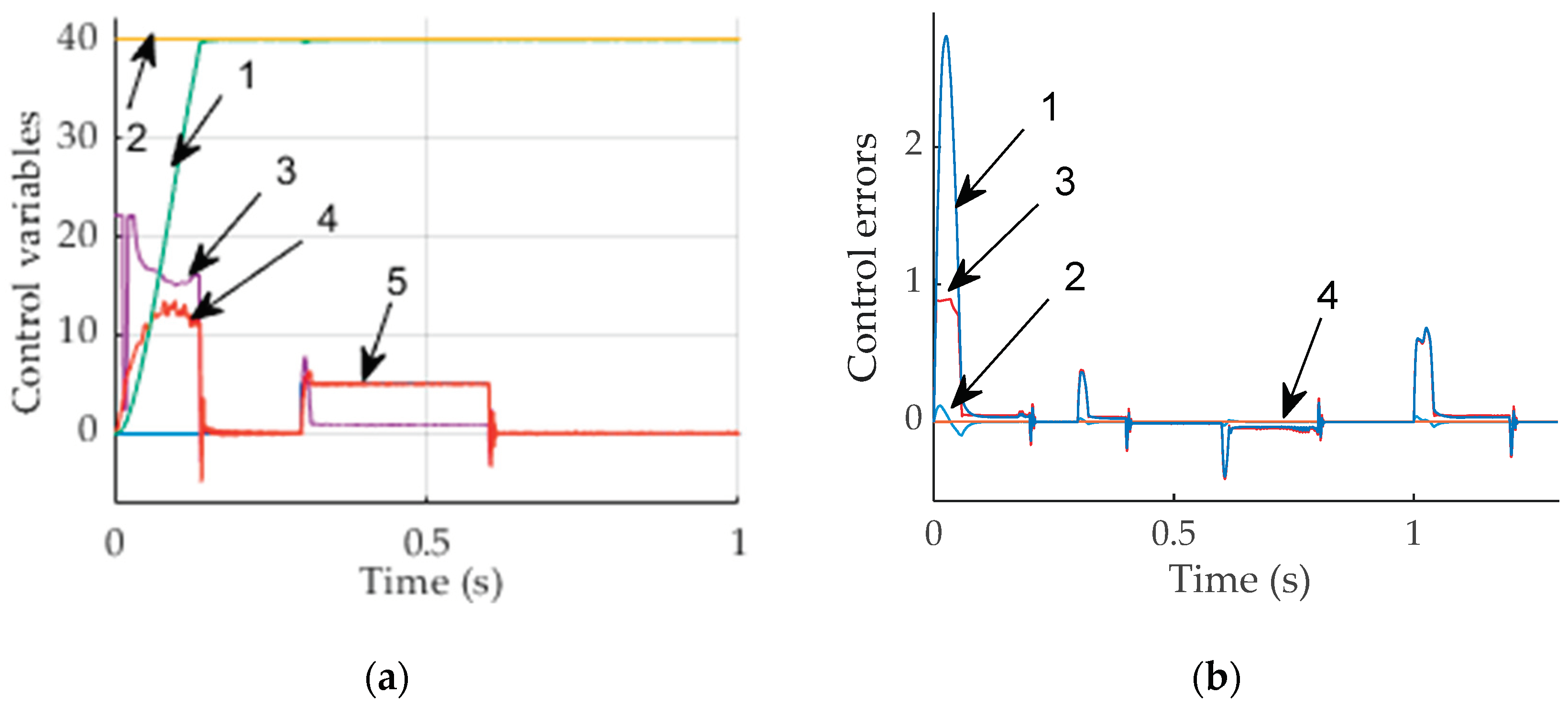
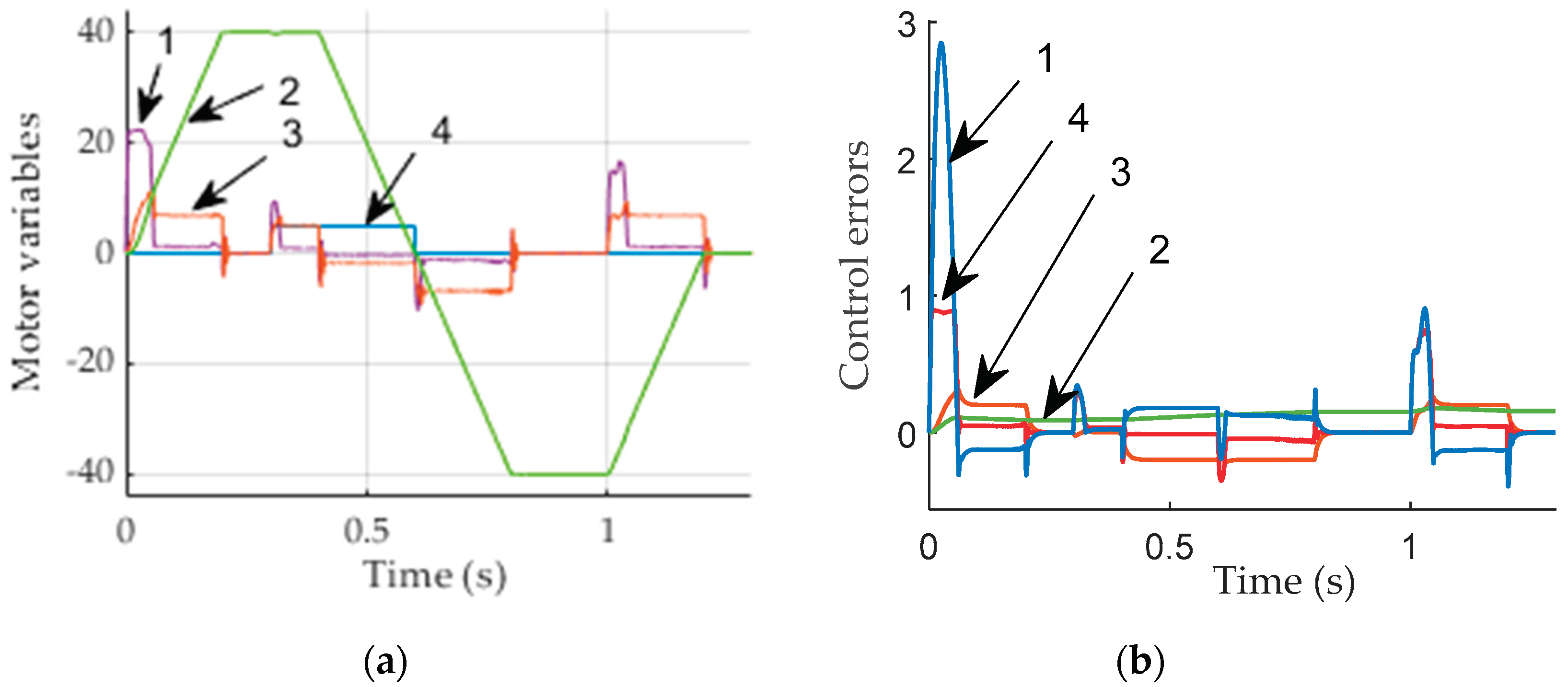
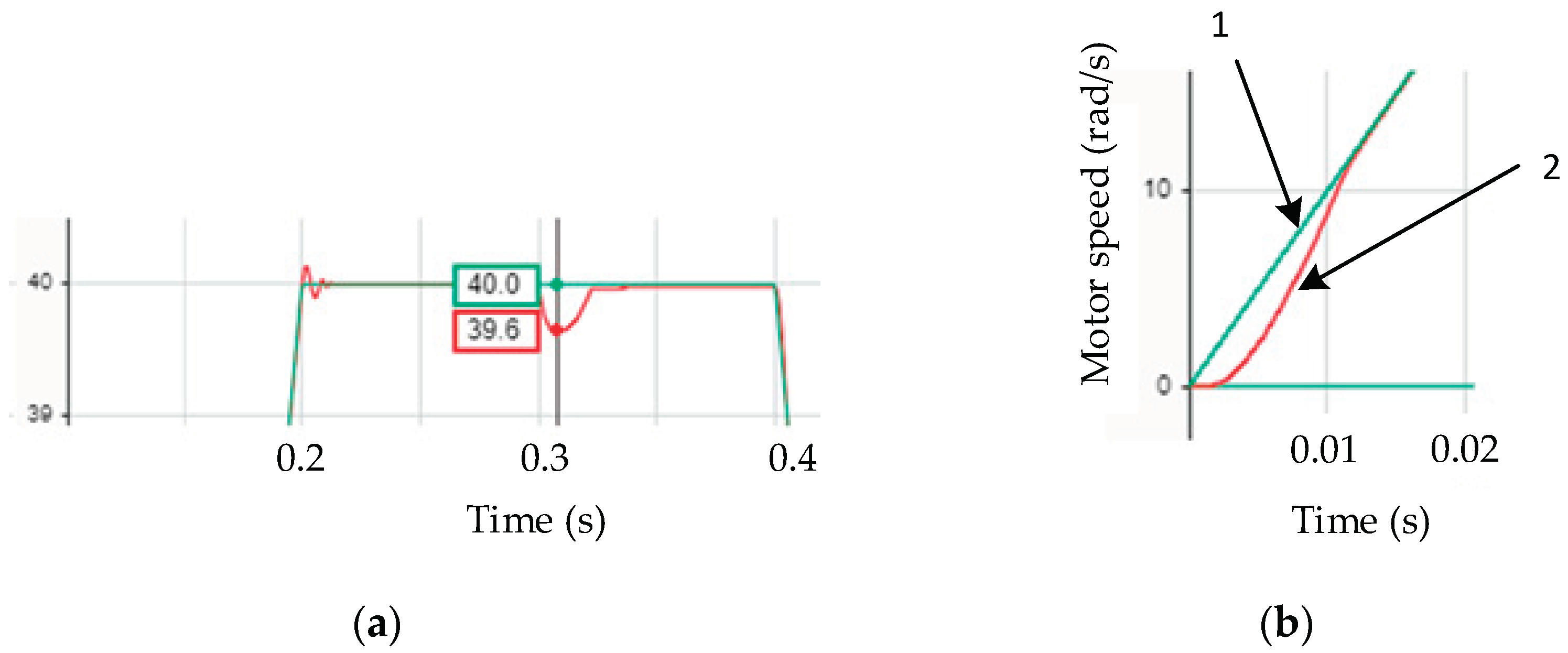
| Parameter | Notation | Data | Units |
|---|---|---|---|
| Magnetizing inductance | 0.295 | H | |
| Stator leakage inductance | 0.07 | H | |
| Stator mutual inductance | 0.07 | H | |
| Rotor leakage inductance | 0.115 | H | |
| Stator resistance | 68 | Ω | |
| Rotor resistance Motor inertia Number of poles |
J p |
4.5 0.034 8 |
Ω |
Disclaimer/Publisher’s Note: The statements, opinions and data contained in all publications are solely those of the individual author(s) and contributor(s) and not of MDPI and/or the editor(s). MDPI and/or the editor(s) disclaim responsibility for any injury to people or property resulting from any ideas, methods, instructions or products referred to in the content. |
© 2024 by the authors. Licensee MDPI, Basel, Switzerland. This article is an open access article distributed under the terms and conditions of the Creative Commons Attribution (CC BY) license (http://creativecommons.org/licenses/by/4.0/).


