1. Introduction
Improvements in the design and construction of civil structures have yielded lighter, more slender floor structures, which, consequently, are increasingly vulnerable to vibrations. While these structures successfully meet the criteria for ultimate limit states, they are at risk of being adversely affected by excessive vibrations induced by human activity [
1,
2]. Notably, such structures encompass a wide array of environments, including but not limited to offices, classrooms, footbridges, concert halls, gyms, shops, operating rooms, and stadiums. Passive vibration control (PVC) methods, particularly via tuned mass dampers (TMDs), have been widely employed when addressing resonance problems within a narrow frequency bandwidth [
3,
4,
5,
6]. TMDs, appreciated for their lack of energy input requirements and reduced maintenance costs, nonetheless face challenges in maintaining optimal performance when dealing with structures exhibiting fluctuating modal parameters or excitation at varying frequency ranges. At lower vibration levels typical of human activity, TMDs may exhibit a dead zone, limiting their effectiveness for in-service vibrations. Additionally, their performance diminishes significantly for non-resonant excitations.
These limitations have spurred a growing interest in active vibration control (AVC) methodologies [
7]. AVC, employing inertial mass actuators, has shown promise in significantly reducing vibrations, thereby allowing lightweight pedestrian structures to meet vibration serviceability limits. Typically, single-input single-output (SISO) AVC systems are utilized, employing a single accelerometer for measuring structure response and a single actuator for control [
8,
9]. However, for specific applications, multi-input multiple-output (MIMO) AVC schemes have been proposed, utilizing multiple accelerometers and actuators [
10]. Despite the potential benefits, the practical implementation of AVC in civil engineering faces various challenges that must be addressed for the field to fully mature. A significant obstacle is the issue of instability arising from the application of active control forces, akin to introducing energy into the structure, potentially destabilizing the closed-control loop with severe consequences [
7]. This instability often stems from inadequate consideration of actuator dynamics in controller design [
11,
12].
To mitigate these challenges, various control strategies have been proposed, with a notable emphasis on direct velocity feedback (DVF) control. For instance, in [
13], a feed-through term (FFT) between structure acceleration and actuator force is combined with ideal integration of modified structure output. Another approach, as proposed in [
14], combines acceleration feedback with a phase-lag compensator and a high-pass filter, executing integral action within the bandwidth of interest. Stability margins of controllers, such as that in [
13], have been improved by approximating the inversion of actuator dynamics, enabling the application of integral resonant control (IRC) theory [
15]. Recently, in [
16], the cutoff frequency of filters used in implementing integral actions in DVF has been considered as a design parameter, impacting the damping performance of DVF concerning the structure’s first vibration mode and actuator natural frequency. While these SISO schemes offer effective active vibration damping, further performance enhancements are believed possible through the utilization of MIMO control schemes. This was initially demonstrated in [
17], wherein an optimal DVF MIMO controller was introduced and subsequently refined in [
10] by incorporating input-output frequency weighting. In [
18], a comprehensive methodology was presented, considering both the nature of human loading and vibration perception. Additionally, the design accounted for significant dynamics and nonlinearities of actuators, crucial for successful practical implementation.
Building upon the common framework proposed in [
18], this study extends the application of MIMO IRC introduced in [
19]. Thus, this research presents a novel application example of MIMO IRC for AVC of pedestrian structures. The steps for implementing AVC are delineated as follows: identification of floor structure and actuator models (
Section 2), determination of optimal actuator placement and control parameters for MIMO IRC control using the proposed common framework (
Section 3), presentation of experimental results (
Section 4), and conclusions and future works (
Section 5).
2. System Model
The standard state-space representation for a typical flexible structure, which comprises
n vibration modes and
p nodes (i.e., possible locations for actuators/sensors and perturbations) is given by:
where
represents the control input vector (i.e., the force imparted by actuators),
denotes the perturbation forces and
is the output vector (sensor measurements, typically acceleration). The matrices
,
,
,
,
and
define the state-space model of the structure. When (
1) is expressed in modal coordinates, these state-space matrices can be explicitly written as follows [
20]:
where
and
are diagonal matrices formed by the natural frequencies (
) and damping ratios (
) respectively; and
is an
matrix. Note that each
kth column is formed by the
kth vibration mode shape. The state vector is defined as:
, where
are the modal coordinates of the structure, and
are their derivatives.
The time-domain system Equations (
1) and (
2) can be transformed into a frequency-domain transfer function matrix relationship given by:
where
.
In this work, inertial mass actuators that generate force by accelerating an inertial mass are utilized. These actuators consist of an inertial (or moving) mass attached to a current-carrying coil, moving in a magnetic field. If
q actuators are used, the
matrix of the actuator linear part can be written as:
where each transfer function
is defined as:
Here,
is the actuator gain parameter,
is the damping ratio,
is the natural frequency of actuator placed at the
node and
models the amplifier dynamics in the voltage mode (see [
21] for more information).
3. Proposed Control Scheme
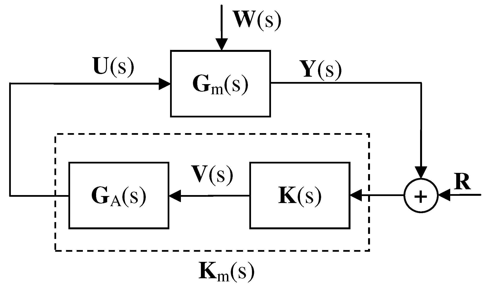
The general control scheme is depicted in
Figure 1, illustrating two primary components. The first component encompasses the dynamics of the flexible structure, represented by
. The second component constitutes the AVC system, comprising the controller, denoted as
, and the shakers, represented by
. This representation delineates the interplay between the structure’s inherent dynamics and the active vibration control system, emphasizing their integral roles in mitigating vibrations and enhancing structural performance.
The MIMO IRC controller proposed in [
22] is herein considered as the following
diagonal matrix:
where
is the IRC configured for
i node. In this specific instance of MIMO IRC, it’s important to note that only the acceleration measured at the node where the actuator is positioned is considered. Similar to the SISO case [
19], controller stability can be achieved as the phase of each transfer function
begins at 180 degrees. Notably, the actuator features two zeros at the origin, steadily decreasing until reaching -180 degrees. It’s worth mentioning that a forthcoming study will address the formal demonstration of stability. This observation underscores the robustness of the MIMO IRC approach in effectively mitigating vibrations and enhancing the structural performance, thereby laying the groundwork for further advancements and insights in the field of active vibration control.
4. Design Methodology Based on the Common Framework
The design methodology consists of:
Identifications and finite element (FE) model calibration
Define the performance index (PI)
Define the strategy to find the optimal controller
Obtain the optimal controller
4.1. Identifications and FE Model Calibration
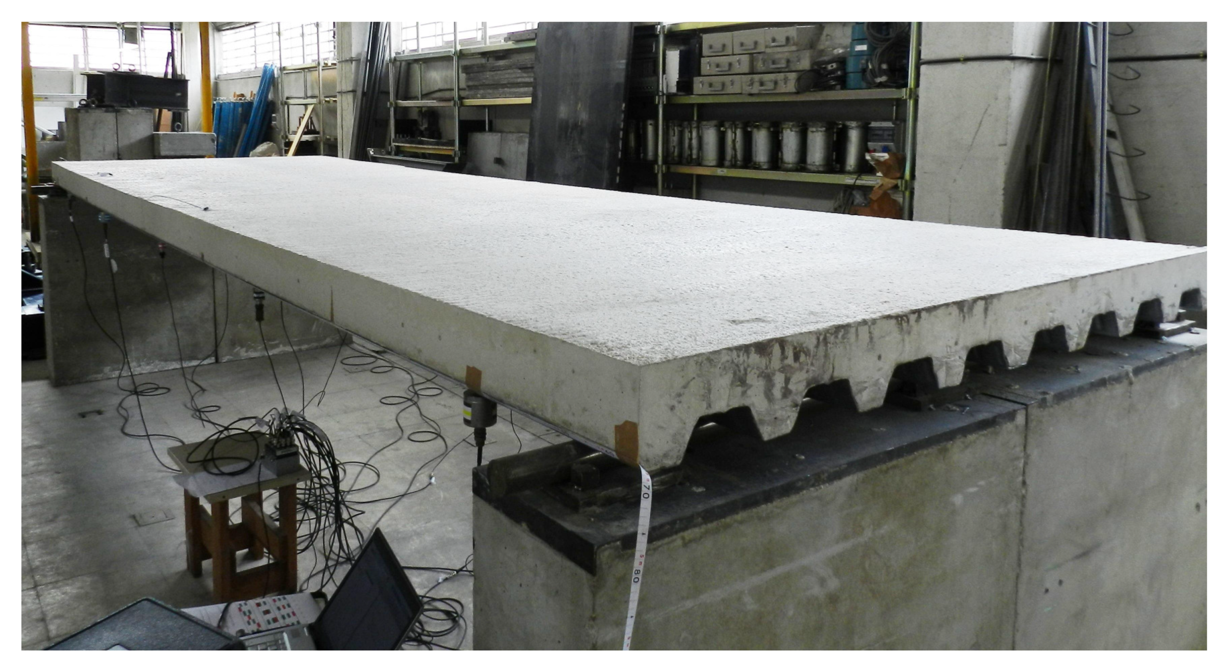
The experimental results were conducted on a full-scale laboratory structure, as depicted in
Figure 2. This structure comprises a slender steel-concrete composite slab with dimensions of 5.8 m × 1.8 m × 0.14 m, resulting in a thickness-span ratio of only 1/40. Control of this structure is achieved using two APS electrodynamic actuators, driven by two power amplifiers (APS 144 and APS 145). Acceleration measurements are performed utilizing a piezoelectric accelerometer (PCB Piezotronics model 393B31). To induce excitations and obtain the experimental frequency response functions (FRFs), a large-sledge impulse hammer (PCB model 086D50) is employed. This experimental setup enables comprehensive investigation and analysis of the structural response under controlled conditions, providing valuable insights into the efficacy of the proposed active vibration control strategies.
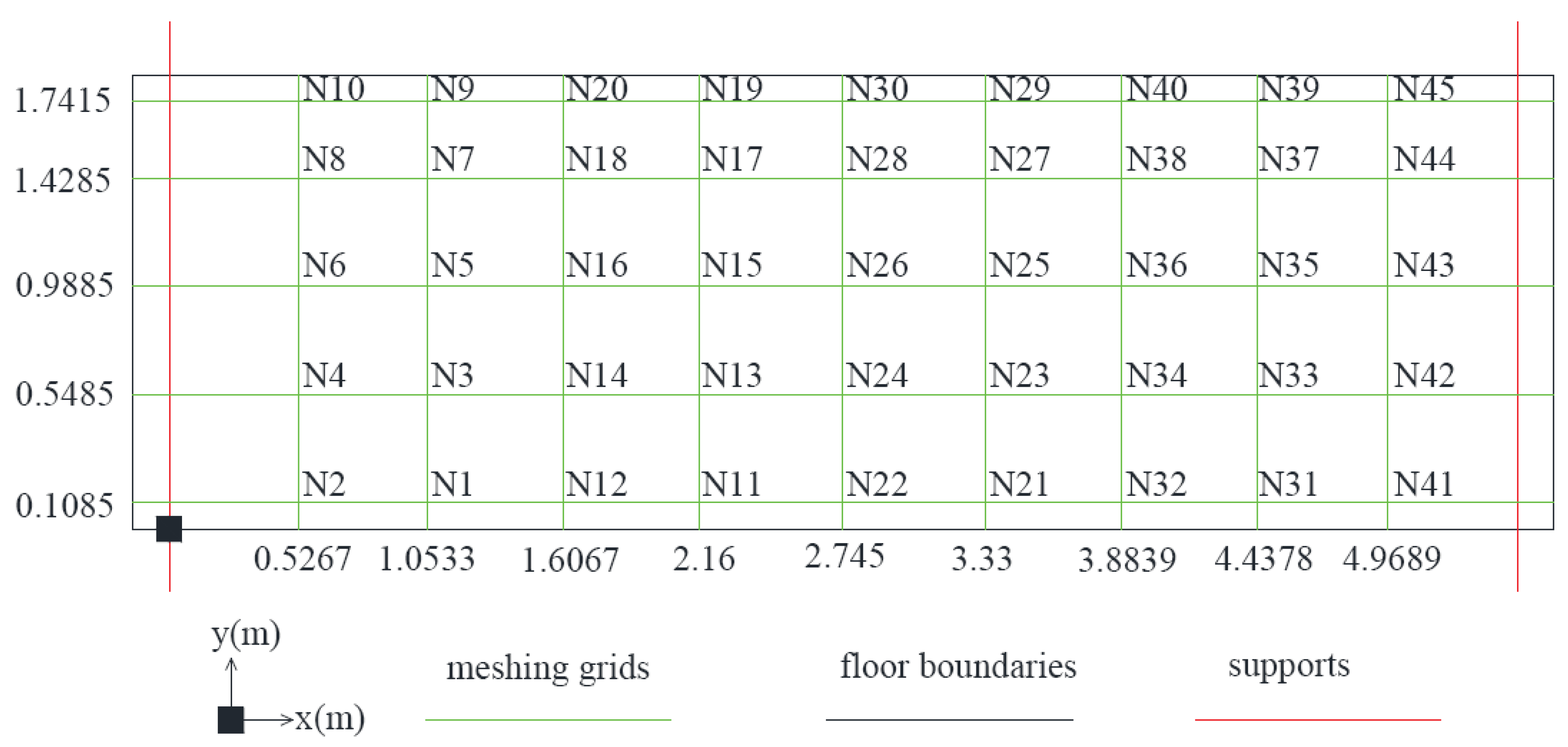
To commence, a Finite Element (FE) model is constructed using ANSYS Multiphysics [
23], employing shell elements and encompassing 45 nodes (refer to
Figure 3). This FE model serves as the basis for selecting appropriate actuator locations capable of mitigating the most dominant vibration modes. Consequently, actuators and accelerometers are strategically positioned at nodes N16 and N22.
Figure 4 illustrates the mode shapes of the first three vibration modes, consisting of two bending modes and one torsional mode. These mode shapes aid in identifying suitable actuator locations for effectively canceling the most significant vibration modes. Notably, the hammer is utilized at node N12, identified as an optimal location for exciting all vibration modes uniformly. This meticulous approach ensures that the experimental setup is finely tuned to capture and address the dominant dynamics of the structure, facilitating accurate assessment and validation of the active vibration control strategies proposed in the study.
Figure 3.
Node numbers and coordinates initialized on the laboratory-based floor structure shown in
Figure 2.
Figure 3.
Node numbers and coordinates initialized on the laboratory-based floor structure shown in
Figure 2.
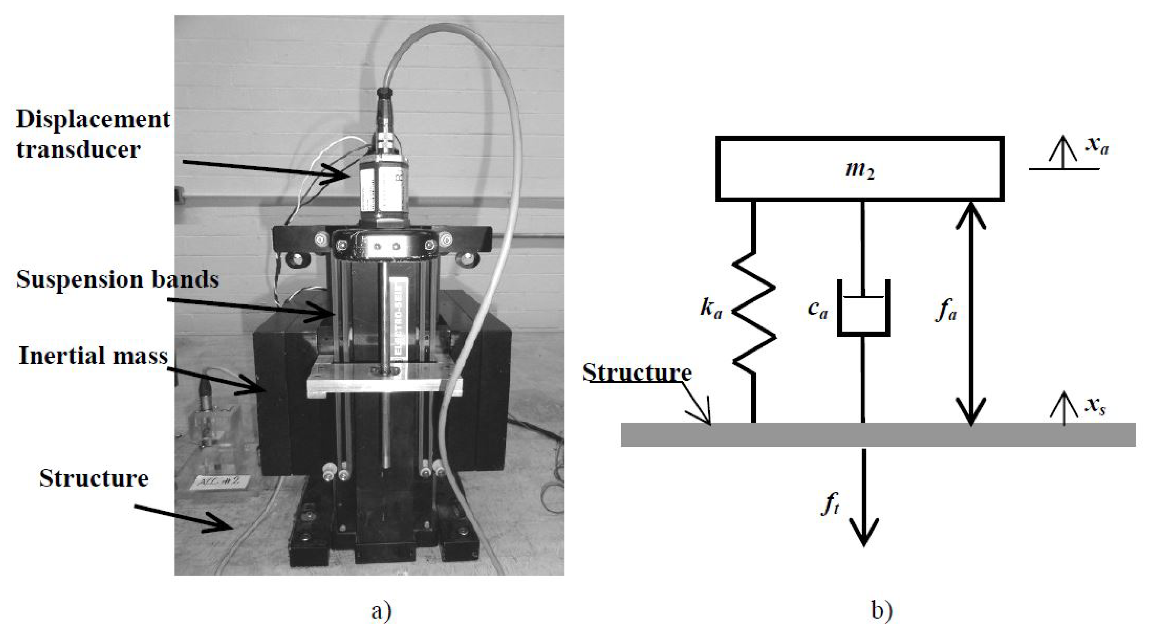
The next step is to identify the structure and actuators. The actuators used in this word are inertial mass actuators (also known as proof-mass actuators) that generate forces through acceleration of an inertial mass to the structure on which it is placed. The actuator consists of an inertial (or moving) mass (denoted as
) attached to a current-carrying coil moving in a magnetic field created by an array of permanent magnets. The inertial mass is connected to the frame by a suspension system, modelled by a spring stiffness
and a viscous damping
[
21] (see
Figure 5).
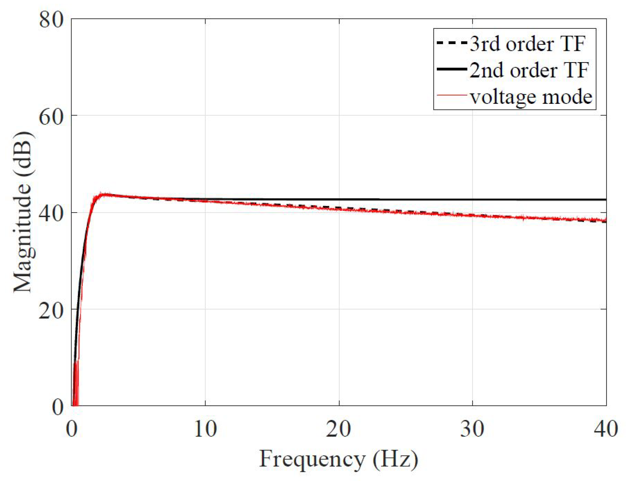
The identification of the actuators parameters (see Equation (
5)) are obtained configured the actuator and its amplifier in voltage mode. The parameters of Equation (
5) have been tuned to adjusted the 3
rd order transfer function of with the measured data of
Figure 6. Thus, the identified actuator parameters are:
N16: , , rad/s and
N22: , , rad/s and
Figure 6.
Inertial mass actuator working in voltage mode.
Figure 6.
Inertial mass actuator working in voltage mode.
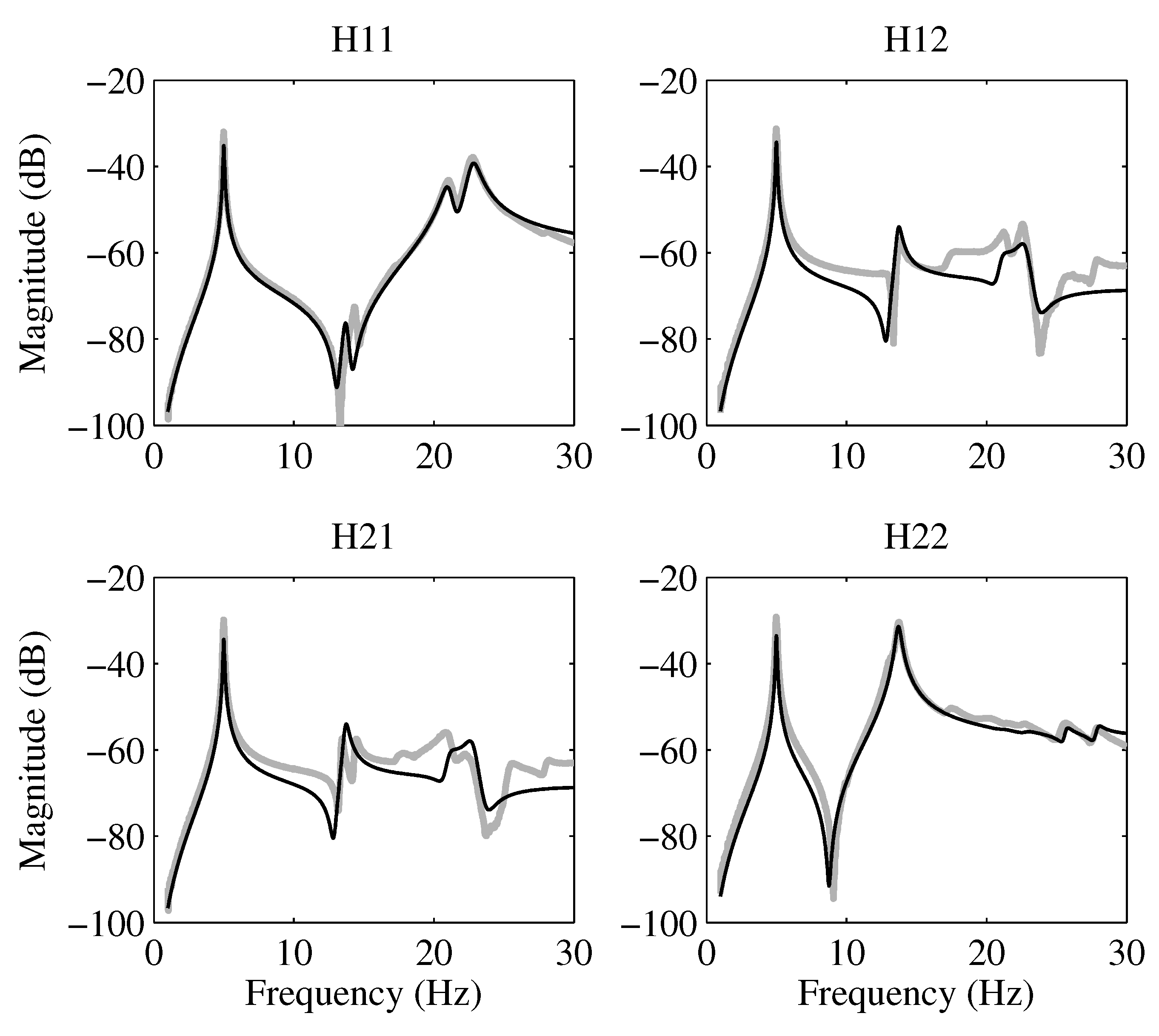
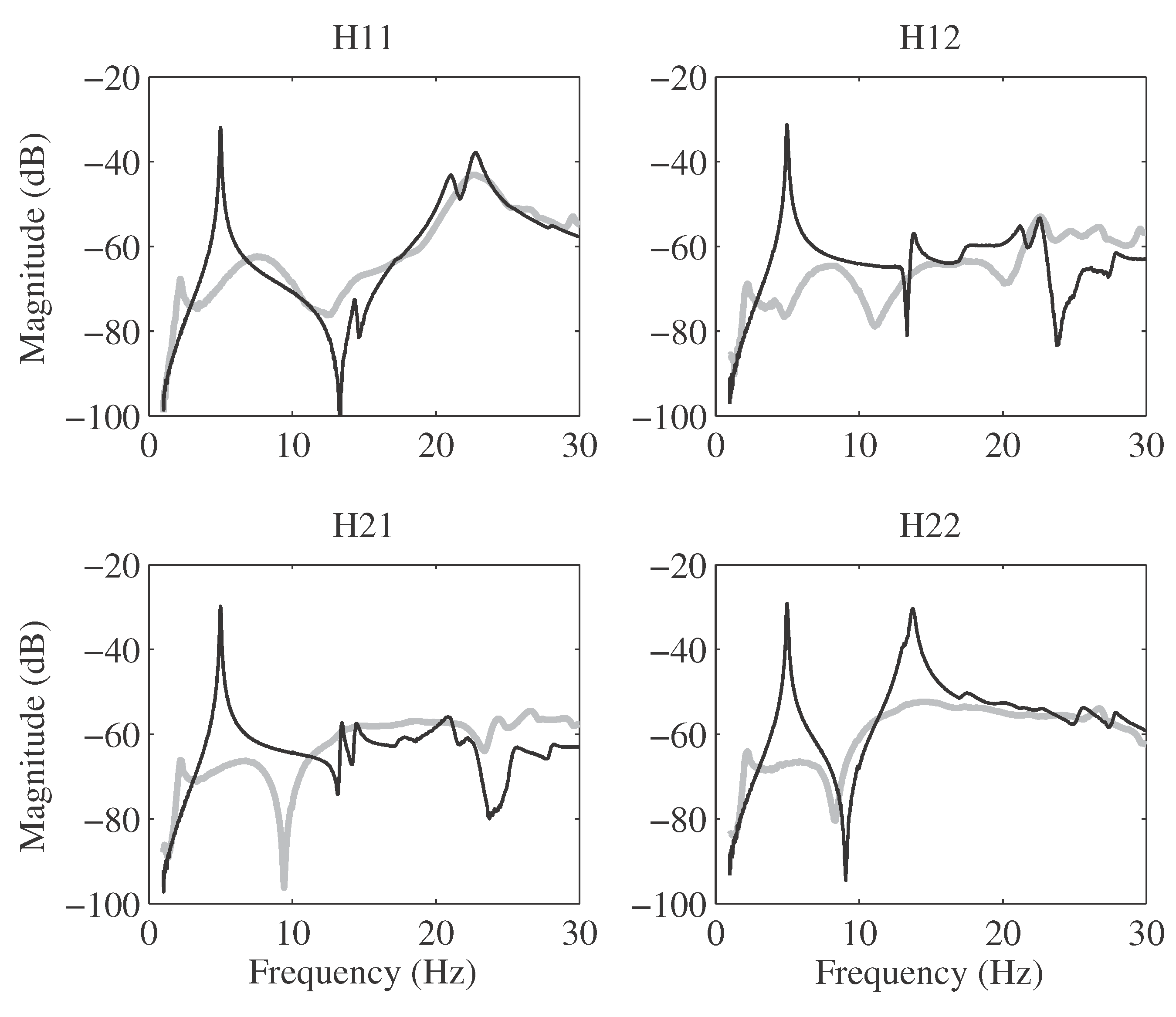
The next step is to identify the structure with the actuators. The Frequency Response Functions (FRFs) between excitation (vertical forces), proportional to the acceleration measured in the actuator moving mass, and the structural accelerations were acquired by applying a band-limited (0.3-50 Hz) white noise signal with a duration of 600 seconds and utilizing a sampling frequency of 1000 Hz. Employing a subspace-based system identification technique, an accurate model of the experimental system was obtained [
24]. Consequently, the first vibration modes were identified with sufficient precision to devise a Multi-Input Multi-Output (MIMO) Integral Resonant Control (IRC) scheme and evaluate the achievable damping in simulations. The FRFs of the measured and modeled system are presented in
Figure 7, demonstrating the effectiveness of the system identification process in capturing the dynamic behavior of the structure. These FRFs serve as crucial benchmarks for validating the proposed MIMO IRC control scheme and assessing its performance in mitigating vibrations across the targeted frequency range.
The algorithm identifies six vibration modes whose parameters are as follows (see (
2)):
Natural frequencies (): rad/s, rad/s, rad/s, rad/s, and rad/s.
Damping ratios (): , , , , and
-
Mode shape ():
- Node N16: , , , , and .
- Node N12: , , , , and .
Figure 7.
Magnitude (in dB) plot of the identified model (black) with the measured FRF (grey) demonstrating excellent alignment between the actual system and its developed model.
Figure 7.
Magnitude (in dB) plot of the identified model (black) with the measured FRF (grey) demonstrating excellent alignment between the actual system and its developed model.
4.2. Performance Index
The proposed Integral Resonant Control (IRC) strategy aims to optimize the performance of the control system by minimizing the peak values of the FRFs associated with , , , and within the frequency range of 0 to 15 Hz. Essentially, the IRC controller prioritizes enhancing the damping characteristics of the primary vibration modes.
Ensuring stability entails rigorous consideration of both actuator dynamics and the high-frequency model of the system, guaranteeing robustness against spillover effects. The Proportional-Integral (PI) term is determined as the maximum value of the FRFs representing the relationship between sensor acceleration and actuator force, as illustrated in
Figure 7, but within the closed-loop system. Given the sensitivity of the structure’s dynamics to actuator placement, leveraging FE modeling aids in identifying optimal actuator locations to effectively suppress critical vibration modes. Accordingly, actuators are positioned at nodes N16 and N22.
The IRC controller is tailored to minimize the peak response of the controlled system within the frequency band of 0 Hz to 15 Hz, thereby aiming to maximize damping primarily in the first two vibration modes illustrated in
Figure 4. These modes hold particular significance concerning human-induced excitation and perception of vibration, as highlighted in references such as [
25] and [
26]. Consequently, a diagonal controller matrix of
with
is employed, representing a MIMO AVC system utilizing two actuators to address the primary vibration modes.
4.3. Controller Optimization
As previously discussed, the approach to identifying the optimal Actuator Mass Dampers (AMDs) involves determining the most effective IRC parameters to minimize the peak values of the FRFs associated with nodes N16 and N22 across the frequency range of 0 Hz to 15 Hz. This optimization task is accomplished through the utilization of the built-in MATLAB function fminsearch, which employs a derivative-free method to locate a local minimum of an unconstrained multivariable function.
During the minimization process, careful consideration is given to the stability of the closed-loop system. Then, the following practical issues haven been considered:
The actuator bandwidth (i.e., frequency response) significantly affects the stability of the overall control scheme and limits the maximum damping imparted to the structure. Specifically, the eigenvalues of the closed-loop state matrix are examined. In instances where unstable eigenvalues are detected, the optimization function is appropriately penalized to ensure system stability. This comprehensive approach ensures that the resulting IRC parameters not only minimize the peak FRFs but also maintain the stability of the controlled system.
The actuator stroke saturation, which also limits the maximum damping imparted, could result in dramatic adverse effects on the actuator performance and its hardware. This issue is important to define the maximum perturbation the controller can damp in its linear behaviour.
The resulting controller is as follows (see (
6)):
5. Experimental Results
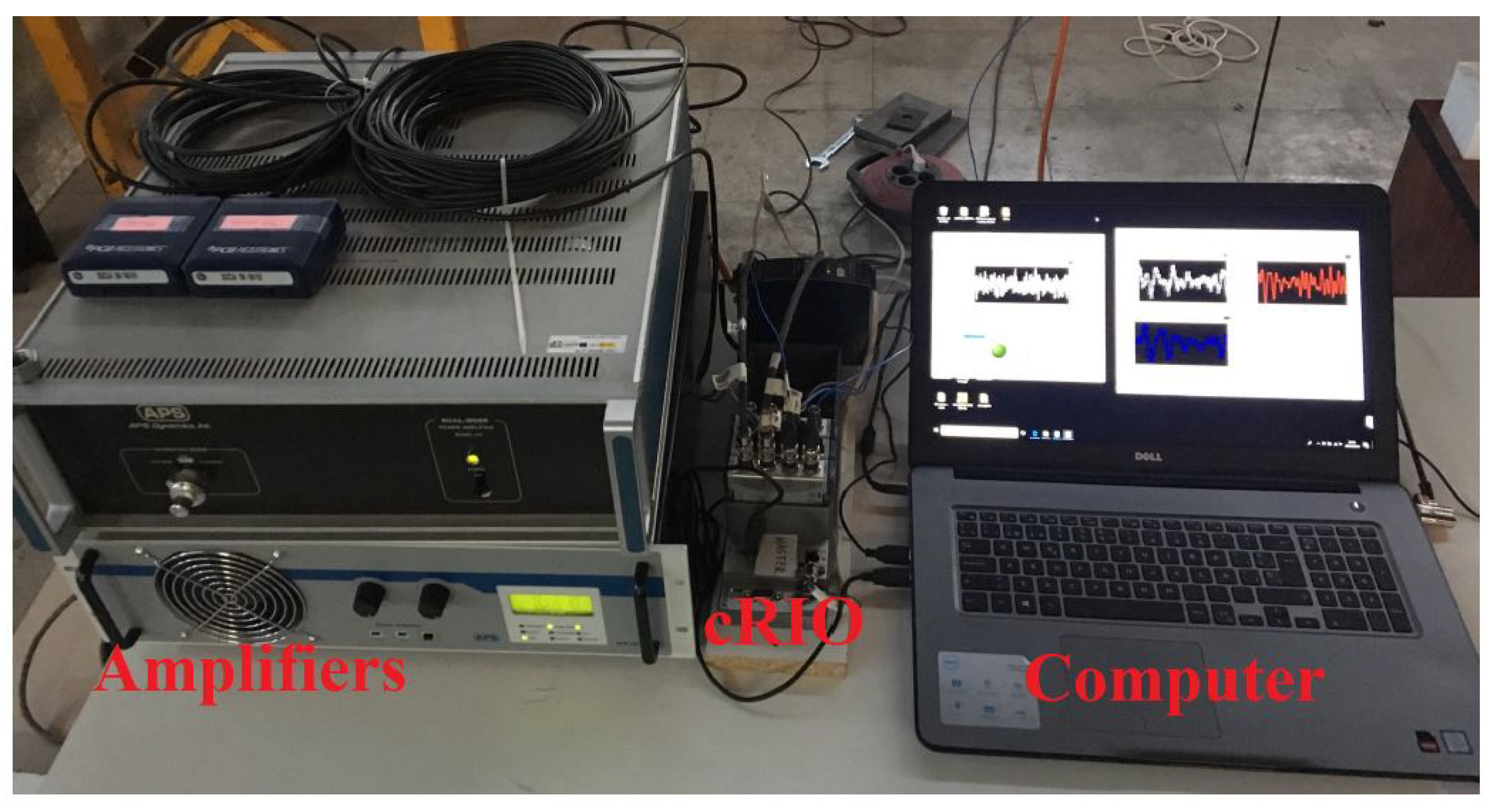
The controls are carried out using LabVIEW Real-Time Module and NI acquisition system: cRIO-9066 equipped with analog output card NI-9203 and IEPE conditioning cards NI-9234 to measure the structure response. It is important to highlight that saturation blocks are included to reduce stroke and force saturation risks. In
Figure 8, it can be seen the cRIO, amplifiers and a computer recording the results coming from the second loop of the block diagram.
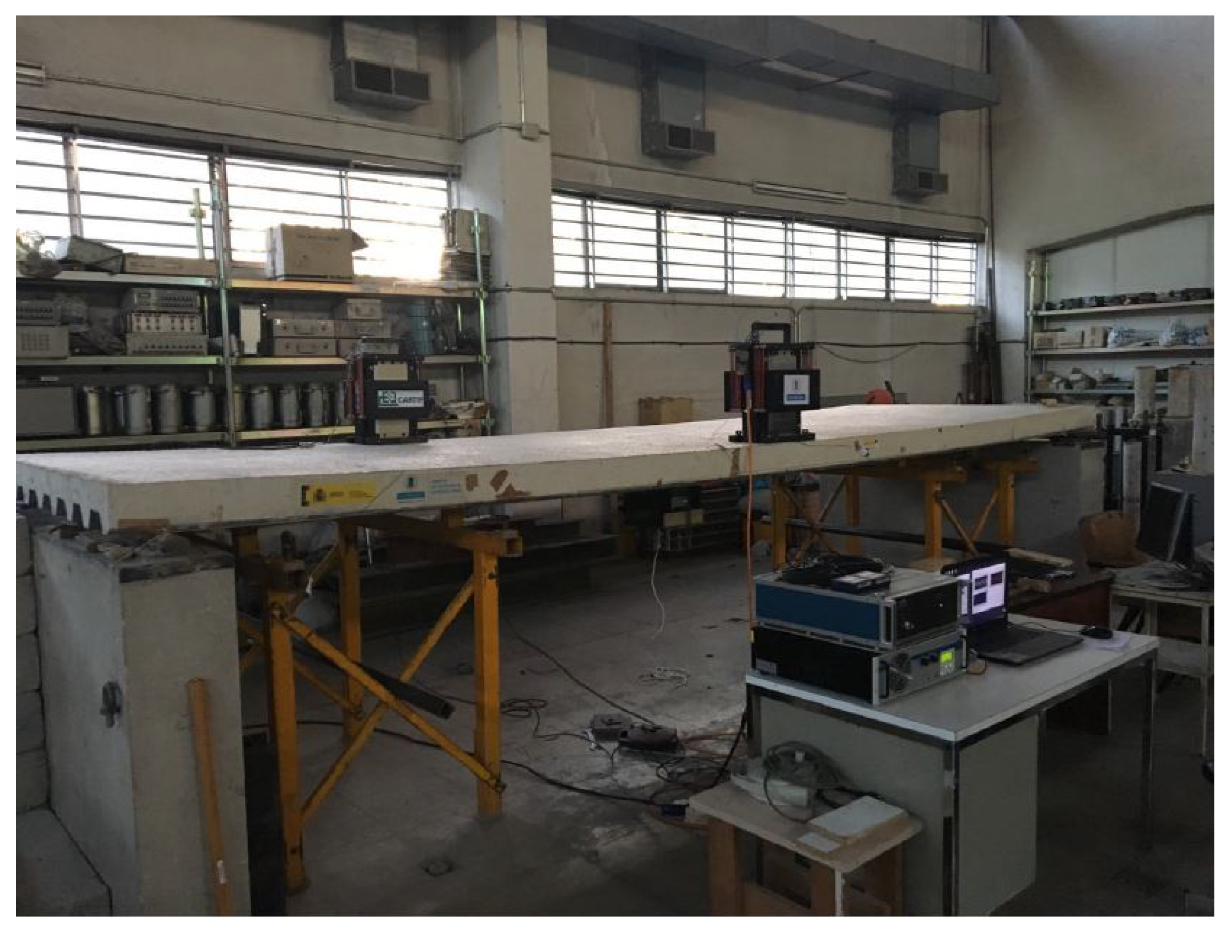
In order to obtain the CL experimental results, impulse hammer (PCB PIEZOTRONICS model 086D50) is used to excite the structure near nodes 16 and 22 (see
Figure 9). Each test includes three impacts to the oor, with an interval of 20 seconds. OL and CL comparisons are depicted in
Figure 10. Notably, the damping of the first mode exceeds 30 dB at nodes 16 and 22, with node 22 exhibiting a damping of over 20 dB. Additionally, a minor peak around 2.2 Hz is evident in the closed-loop responses. This peak is attributed to the characteristics of the inertial actuator utilized. Its presence governs instability at lower frequencies, where the poles of the actuator may become unstable if the values of
and
are significantly increased.
The results depicted in
Figure 10 underscore the effectiveness of the devised MIMO IRC scheme in efficiently damping multiple unmodeled structural modes while maintaining stability. Importantly, the stability conditions established in this study ensure that any MIMO controller adhering to these criteria is inherently robust against spillover issues, thereby making it suitable for practical implementation across various engineering applications.
It is noteworthy that the methodology employed in this research can serve as a blueprint for designing stability-based AVC schemes capable of addressing similar low-frequency challenges encountered in different control contexts. By leveraging alternative control laws, which may have been previously hindered by comparable low-frequency limitations, engineers can now employ a similar approach to develop robust and effective AVC strategies tailored to their specific system requirements.
6. Conclusions
This study contributes significantly by extending a previously established generalized framework and a systematic design methodology to introduce a novel application of Multiple-Input Multiple-Output (MIMO) Integral Resonant Control (IRC) for Active Vibration Control (AVC). By leveraging this approach, we have effectively addressed the complexities inherent in controlling vibration dynamics across multiple degrees of freedom, thereby offering a versatile solution applicable to diverse structural systems. The model framework adopted in this work provides a robust foundation for analyzing and optimizing the performance of the proposed control scheme. Through extensive simulations and rigorous experimental validations conducted on a full-scale laboratory structure, we have demonstrated the efficacy and practical feasibility of the proposed MIMO IRC strategy in real-world applications. The consistent alignment between simulation results and experimental findings underscores the reliability and accuracy of our control approach in effectively attenuating unwanted vibrations across the targeted frequency spectrum.
Furthermore, the insights gained from this study are not only limited to the specific application domain explored here but also hold broader implications for the design and implementation of MIMO AVC schemes under varying operational constraints. The established conditions and methodologies offer valuable guidance for engineering practitioners seeking to address low-frequency restrictions while deploying alternative control laws. By providing a comprehensive understanding of the underlying principles governing MIMO AVC systems, our work lays the groundwork for future advancements in adaptive control strategies tailored to diverse structural configurations and operational environments. Ultimately, this research contributes to the ongoing evolution of advanced control techniques aimed at enhancing the performance, safety, and longevity of complex engineering structures across various industrial sectors.
Finally, future works will deduce the stability conditions for this novel IRC control scheme combining the Negative Imaginary Frecuency Response property and the Small-Gain theorem [
27] . These sufficient stability conditions will include the actuator dynamics and the model of the system, deeming the resulting controller robust to spillover.
Author Contributions
For research articles with several authors, a short paragraph specifying their individual contributions must be provided. The following statements should be used “Conceptualization, Emiliano Pereira and Sumeet S. Alphale; Emiliano Pereira and Iván M. Díaz; software, Iván M. Díaz and Xidong Wang; validation, Xidong Wang, Iván M. Díaz and Emiliano Pereira; formal analysis, Emiliano Pereira and Sumeet S. Aphale; investigation, Emiliano Pereira, Iván M. Díaz and Sumeet S. Aphale; resources, Emiliano Pereira, Iván M. Díaz and Sumeet S. Aphale; data curation, Wang Xidong; Emiliano Pereira and Wang Xidong; writing—review and editing, Iván M. Díaz and Sumeet S. Aphale; visualization, X.X.; supervision, Emiliano Pereira; project administration, Iván M. Díaz; funding acquisition, Emiliano Pereira and Iván M. Díaz. All authors have read and agreed to the published version of the manuscript.”, please turn to the
CRediT taxonomy for the term explanation. Authorship must be limited to those who have contributed substantially to the work reported.
Funding
This research was funded by PID2022-140117NB-I00 (Spanish Government) and National Natural Science Foundation of China (No. 52308220).
Acknowledgments
In this section you can acknowledge any support given which is not covered by the author contribution or funding sections. This may include administrative and technical support, or donations in kind (e.g., materials used for experiments).
Conflicts of Interest
The authors declare no conflict of interest.
References
- Ebrahimpour, A.; Sack, R. A review of vibration serviceability criteria for floor structures. Computers & Structures 2005, 83, 2488–2494. [Google Scholar] [CrossRef]
- Fanning, P.J.; Healy, P.; Pavic, A. Pedestrian Bridge Vibration Serviceability: A Case Study in Testing and Simulation. Advances in Structural Engineering 2010, 12, 861–873. [Google Scholar] [CrossRef]
- Chen, J.; Han, Z.; Xu, R. Effects of human-induced load models on tuned mass damper in reducing floor vibration. Advances in Structural Engineering 2019, 22, 2449–2463. [Google Scholar] [CrossRef]
- Tubino, F.; Piccardo, G. Tuned Mass Damper optimization for the mitigation of human-induced vibrations of pedestrian bridges. Meccanica 2015, 50, 809–824. [Google Scholar] [CrossRef]
- Li, Q.; Fan, J.; Nie, J.; et al. Crowd-induced random vibration of footbridge and vibration control using multiple tuned mass dampers. Journal of Sound and Vibration 2010, 329, 4068–4092. [Google Scholar] [CrossRef]
- Caetano, E.; Cunha, A.; Moutinho, C.; et al. Studies for controlling human-induced vibration of the Pedro e Ines footbridge, Portugal. Part 2: Implementation of tuned mass dampers. Engineering Structures 2010, 32, 1082–1091. [Google Scholar] [CrossRef]
- Hudson, M.; Reynolds, P. Implementation considerations for active vibration control in the design of floor structures. Engineering Structures 2012, 44, 334–358. [Google Scholar] [CrossRef]
- Casado, C.M.; Díaz, I.M.; Sebastián, A.V.; et al. Implementation of passive and active vibration control on an in-service footbridge. Structural Control and Health Monitoring 2013, 20, 70–87. [Google Scholar] [CrossRef]
- Pelaez-Rodríguez, C.; Magdaleno, A.; Iglesias-Pordomino, A.; et al. Evolutionary computation-based active mass damper implementation for vibration mitigation in slender structures using a low-cost processor. Actuators 2023, 12, 254. [Google Scholar] [CrossRef]
- Pereira, E.; Díaz, I.M.; Hudson, E.J.; et al. Optimal control-based methodology for active vibration control of pedestrian structures. Engineering Structures 2014, 80, 153–162. [Google Scholar] [CrossRef]
- Alujević, N.; Zhao, G.; Depraetere, B.; et al. H2 optimal vibration control using inertial actuators and a comparison with tuned mass dampers. Journal of Sound and Vibration 2014, 333, 4073–4083. [Google Scholar] [CrossRef]
- Chesne, S.; Milhomem, A.; Collette, C. Enhanced damping of flexible structures using force feedback. Journal of guidance, control and dynamics 2016, 39, 1654–1658. [Google Scholar] [CrossRef]
- Díaz, I.M.; Reynolds, P. Robust saturated control of human-induced floor vibrations via a proof-mass actuator. Smart Materials and Structures 2009, 18, 125024. [Google Scholar] [CrossRef]
- Díaz, I.M.; Reynolds, P. Acceleration feedback control of human-induced floor vibrations. Engineering Structures 2010, 32, 163–173. [Google Scholar] [CrossRef]
- Aphale, S.S.; Fleming, A.J.; Moheimani, S.O.R. Integral resonant control of collocated smart structures. Smart Materials and Structures 2007, 16, 439–446. [Google Scholar] [CrossRef]
- Wang, X.; Pereira, E.; Díaz, I.M.; et al. Velocity feedback for controlling vertical vibrations of pedestrian-bridge crossing. practical guidelines. Smart Structures and Systems 2018, 22, 95–103. [Google Scholar] [CrossRef]
- Hanagan, L.; Kulasekere, E.; Walgama, K.; Premaratne, K. Optimal Placement of Actuators and Sensors for Floor Vibration Control. Journal of Structural Engineering 2000, 12, 1380–1387. [Google Scholar] [CrossRef]
- Wang, X.; Pereira, E.; García-Palacios, J.H.; et al. A general vibration control methodology for human-induced vibrations. Structural Control and Healt Monitoring 2019, 26, e2406. [Google Scholar] [CrossRef]
- Díaz, I.M.; Pereira, E.; Reynolds, P. Integral resonant control scheme for cancelling human-induced vibrations in light-weight pedestrian structures. Structural Control and Health Monitoring 2012, 19, 55–69. [Google Scholar] [CrossRef]
- Gawronski, W.K. “Advanced structural dynamics and active control of structures”, Mechanical engineering series. Springer Link; 2004.
- Vibration control of active structures. Springer, fourth edition, 2017.
- Bhikkaji, B.; Moheimani, S.; Petersen, I. “A Negative Imaginary Approach to Modeling and Control of a Collocated Structure”. IEEE/ASME Transactions on Mechatronics 2012, 17, 717–727. [Google Scholar] [CrossRef]
- ANSYS Multiphysics, Release 2022 R2, Help System, ANSYS Inc., 2022.
- McKelvey, T.; Akay, H.; Ljung, L. Subspace based multivariable system identification from frequency response data. IEEE Transactions on Automatic Control 1996, 41, 960–979. [Google Scholar] [CrossRef]
- International Standards Organization. ISO 2631-1: Mechanical Vibration and shock- Evaluation of human exposure to whole-body vibration- Part 1- General Requirements, 1997.
- Wang, X.; Díaz, I.M.; Pereira, E. Mimo control design including input-output frequency weighting for human-induced vibrations. In 6th European Conference on Structural Control - EACS 2016, 2016.
- Patra, S.; Lanzon, A. Stability Analysis of Interconnected Systems With “Mixed” Negative-Imaginary and Small-Gain Properties. IEEE Transactions on Automatic Control 2011, 56, 1395–1400. [Google Scholar] [CrossRef]
|
Disclaimer/Publisher’s Note: The statements, opinions and data contained in all publications are solely those of the individual author(s) and contributor(s) and not of MDPI and/or the editor(s). MDPI and/or the editor(s) disclaim responsibility for any injury to people or property resulting from any ideas, methods, instructions or products referred to in the content. |
© 2024 by the authors. Licensee MDPI, Basel, Switzerland. This article is an open access article distributed under the terms and conditions of the Creative Commons Attribution (CC BY) license (http://creativecommons.org/licenses/by/4.0/).
