1. Introduction
Tunnel stability is greatly affected by the creep characteristics of surrounding rocks. Several studies on engineering projects confirm that the instability and failure of tunnels are typically caused by long-term creep deformation [
1,
2,
3,
4,
5,
6,
7]. Hence, the investigation of the creep characteristics of surrounding rocks is of considerable practical significance. Currently, creep characteristics are measured and monitored mainly through lab tests and numerical simulation. Lab tests are usually performed on intact rock blocks [
8,
9,
10,
11,
12,
13,
14,
15]. However, compared with those of rock blocks, the creep characteristics of rock mass containing various cracks are more significant and their creep parameters are considerably lower. Hence, creep parameters obtained from rock blocks cannot be directly used for the creep analysis of rock mass [
16,
17,
18]. An in situ creep test of rock mass is an effective method to determine the creep deformation characteristics of rock mass. However, in situ tests are not suitable for practical application owing to their complexity and high cost. The inversion of surrounding rock mechanical parameters based on field monitored deformation has been widely applied since Kavanagh and Clough [
19] proposed a finite element method for the inversion of elastic moduli of rocks. Sakurai and Takeuchi [
20] reported inversion of the viscoelastic creep parameters and initial crustal stress field of surrounding rocks. Recently, parameter-inversion-based trial methods such as the bisection method and golden section method have been introduced. For instance, Kirsten and Had [
21] proposed an inversion method based on the monitored deformation of surrounding rocks in tunnels. Bertuzzi [
22] proposed inversion of elastic modulus and crustal stress of surrounding rocks in tunnels based on monitored displacements. Luo et al. [
23] applied the golden section method to the tunnel rock mass parameter inversion and excavation support calculation based on the in situ monitored displacement. With the development of mathematical algorithms, machine learning and intelligent algorithms such as neural networks have been applied for parameter inversion of rock mass [
24,
25]. Nevertheless, the inversion analysis in the above studies uses parameters based on the monitored deformation (elastic modulus, cohesion, and frictional angle) of rock mass. It considers the additional steric effect caused by the support structure of the working face but not the effect of creep characteristics of rock mass on deformation. This provides inaccurate inversion results. As the distance of the working face from the monitoring section increases, the steric effect becomes negligible; as a result, the effect of creep characteristics on deformation becomes prominent, especially in the soft rock mass. The deformation of surrounding rocks correlates with not only the combination, parameters, construction timing, and other aspects of the supporting structure but also the pouring time of the reinforced concrete lining after the support is installed. Early pouring of reinforced concrete will lead to excessively large pressure of the lining in the later stage, whereas late pouring may induce failure of the support due to overload. The optimal construction time of the lining can be determined by numerical simulation that considers the rock mass creep effect.
This study investigated a diversion tunnel in a water diversion project in Xinjiang, China. The tunnel is 283 km in length and 428 m in depth on average, and it was constructed using the open TBM method to a diameter of 7.03 m with an excavation step of 1.8 m. The rocks in XZ42+640~45+000 and XZ66+000~69+132 are mainly black mudstone, with significant creep characteristics, and considerably affect the stability of the surrounding rocks. Moreover, it is difficult to reasonably determine the pouring time of the reinforced concrete lining. In this study, a lab creep test of mudstone collected from target sections was conducted and the appropriate creep constitutive model was determined. Then, the Burgers model integrated with the Mohr–Coulomb element was used to determine the yield creep characteristics of rock mass. Furthermore, 100 orthogonal tests using random creep parameters were conducted and the genetic algorithm-optimized back propagation (GA-BP) neural network inversion model was established. The creep parameters for the mudstone under investigation were obtained from the real-time long-term deformation data of the arch and sidewall obtained from field monitoring. Using these parameters, the stress of the support and lining was analyzed, and consequently, the earliest and latest timings of lining construction were determined.
2. Background
The diversion tunnel consists of 42.65% of Type I, 43.91% of Type III, 11.60% of Type IV, and 1.84% of Type V surrounding rocks. Both XZ42+640~45+000 and XZ66+000~69+132 mostly comprise mudstone and glutenite, two types of lithology are distributed alternately in some tunnel sections, and the surrounding rocks are mostly type IV. In addition, the tunnel segment with the fault fracture zone passing through it has type V surrounding rocks. The mudstone is black, gray-black, and gray-green, and the joints and fissures are well developed, exhibiting mainly three groups of fissures. The support is mainly composed of C30 shotcrete (thickness = 15 cm), ϕ22 anchor bolts in full cross-section (space = 0.9 m), a steel arch (HW150 structural steel, space = 1.8 m), and a C35 reinforced concrete lining. Specific parameters of the support materials and surrounding rocks are provided in
Table 1 and
Table 2.
3. Lab Tests
3.1. Micro- and Meso-Structures and Mineral Composition Analysis
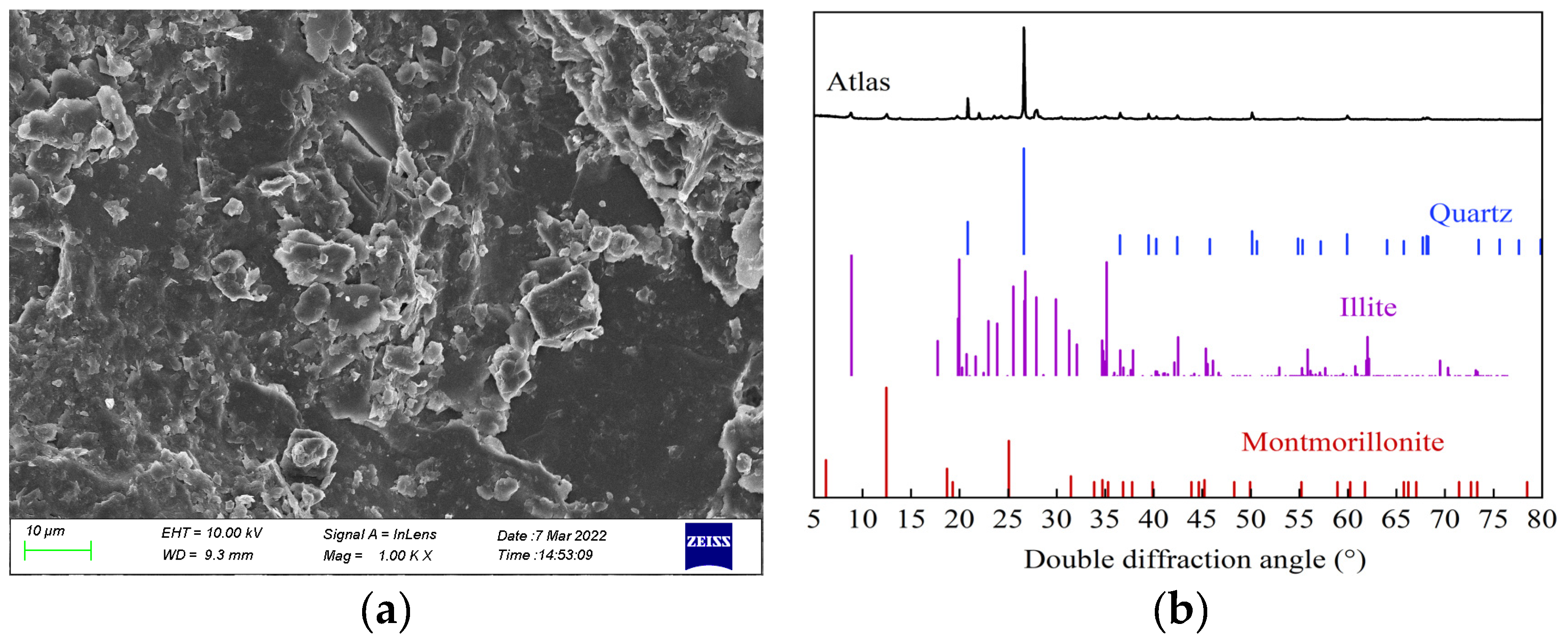
The collected mudstone samples were characterized by scanning electron microscopy (SEM) and X-ray diffraction analysis (XRD) to clarify the micro- and meso-structures and mineral composition identification, respectively.
Figure 1 reveals that the minerals of the mudstone samples are predominantly quartz, hydrophilic montmorillonite, illite, and other clay minerals. The mineral structure is composed of a large number of loosely arranged fine-flake materials. The mudstone has high porosity, strong water absorption, and low strength, and its creep characteristics are mainly affected by clay minerals.
3.2. Tri-Axial Compressive Creep Test
In the tri-axial compressive creep test, the specimens were subjected to incremental loading at 60%, 70%, 80%, 85%, 90%, and 95% of the peak intensity, maintaining each load for 72 h.
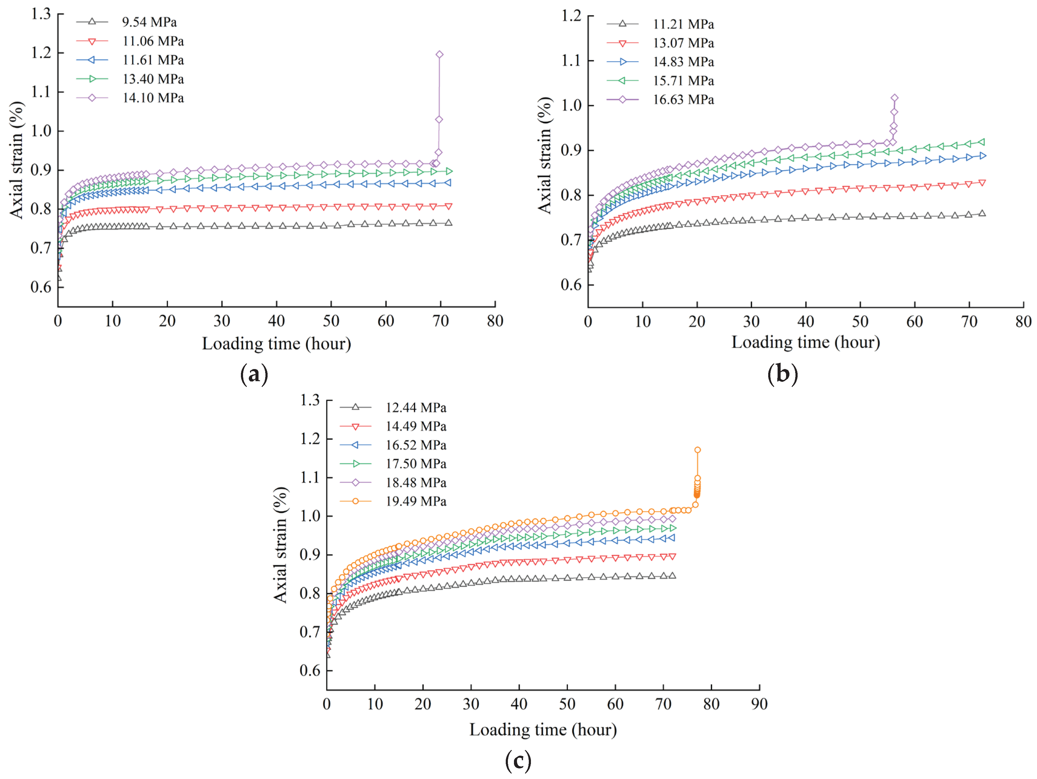
Figure 2 shows the strain–time process curve of mudstone. Chen’s method [
26] was adopted to convert this curve into a strain–time curve under loading conditions, as shown in
Figure 3.
According to
Figure 2 and
Figure 3, the strain of mudstone under different levels of loads can be divided into transient strain and creep strain. As the axial loading stress increases, the transient strain increases. The higher the slope of the creep curve, the more significant are the creep characteristics of the rock. With continuously increasing axial load, the microcracks in the rock compresses and closes, leading to volumetric compression and increase in the volumetric strain. The annular strain of the rock prior to the accelerated creep is extremely small; therefore, the volumetric strain at this stage is basically determined by the axial strain. After the accelerated creep, the volumetric strain decreases rapidly, indicating that the lateral strain increases considerably and significant dilatation failure occurs. In addition, the axial loading stress affects the creep deformation characteristics of rock. Under the first- and second-order deviatoric stress, the strain rate tends to be zero after the transient decelerated creep, which is defined as the decay creep stage. Under the third-, fourth- and fifth-order deviatoric stress, two stages of decelerated creep and isokinetic creep occur; this is defined as the steady creep stage. Under the last stage of deviatoric stress, the rock sample presents decelerated creep in the early stage, and then enters the steady creep stage. When the axial strain exceeds a certain limit, the rock undergoes significant accelerated deformation and ultimately fails.
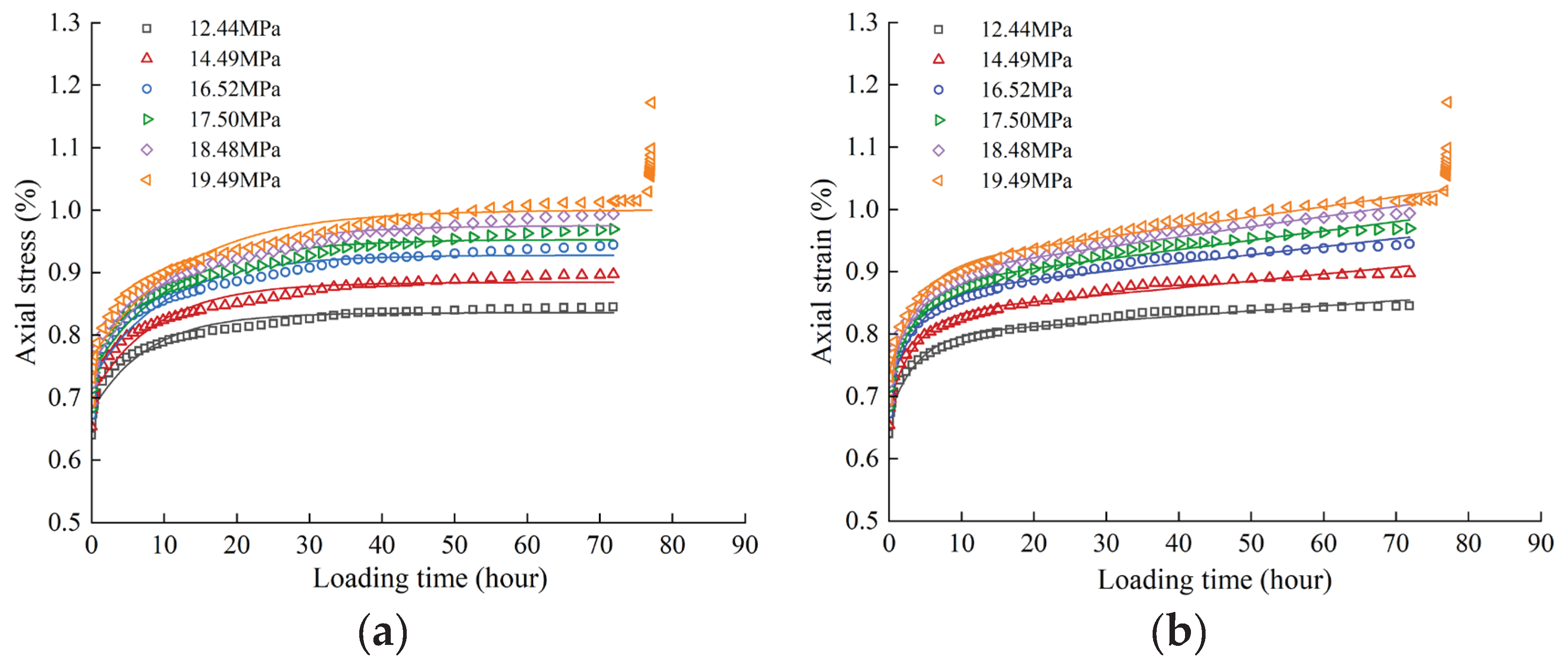
Figure 3 presents
ε–
t curves that have characteristics closest to those of the general Kelvin and Burgers models. As the strain rate gradually becomes constant with time, the general Kelvin model exhibits decay creep, whereas the Burgers model exhibits steady creep. The parameters in the two models are fitted for
σ3 = 6 MPa, as shown in
Figure 4.
Table 3 and
Table 4 show the specific fitting values and equations used.
Although both general Kelvin and Burgers models have sufficient goodness-of-fit, the Burgers model shows a better performance than the general Kelvin model. For the Burgers model, except for the curve during the last stage, the goodness-of-fit of the curve in each stage reaches above 98%, reflecting creep characteristics including the transient strain, decelerated strain, and steady strain in all stages. Despite a goodness-of-fit of over 90% in the general Kelvin model, the model does not reflect the full creep characteristics similar to those exhibited by the Burgers model. Therefore, this study adopted the Burgers model to describe the creep characteristics of mudstone in this project.
4. Creep Model of Surrounding Rock and Parameter Determination
4.1. Determination of Creep Model of Surrounding Rocks
Because of certain differences between the physical and mechanical characteristics of rock block and rock mass, the lab test results of rock blocks cannot be directly applied to the analysis in practical engineering. Although the Burgers model can describe the mudstone creep characteristics, it cannot reflect the yield characteristics of rock mass. Hence, the Burgers model needs to be modified [
27,
28,
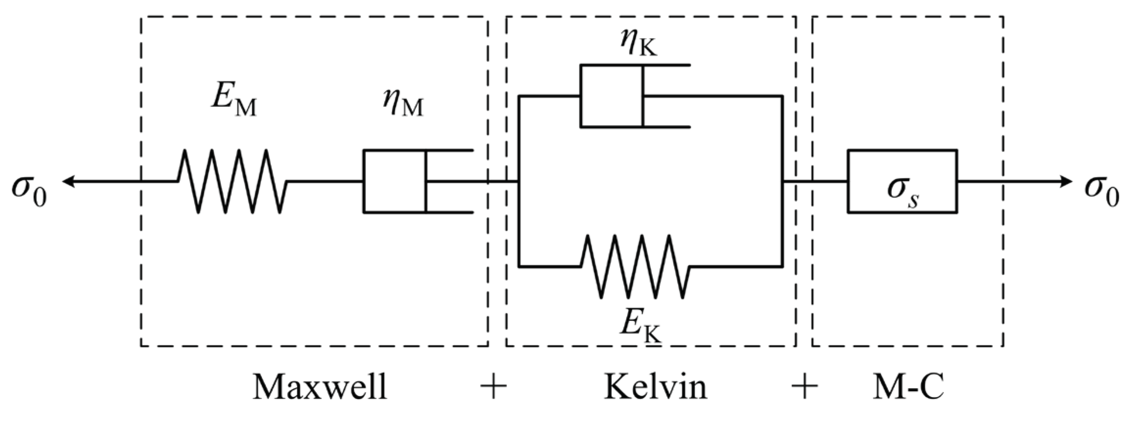
29]. Specifically, the Burgers–Mohr model is developed by integrating the Mohr–Coulomb and Burgers models in series. The Burgers model (which is a series connection of the Maxwell and Kelvin body) shows viscoelastic characteristics, and the Mohr–Coulomb model exhibits plastic characteristics; thus, the corrected Burgers–Mohr model shows visco-elastoplastic characteristics and is better suited to represent the long-term deformation and yield characteristics of surrounding rocks.
Figure 5 shows the elements of the Burgers–Mohr model.
(1) If
σ <
σs, the Burgers–Mohr model reduces to the Burgers model:
(2) If
σ ≥
σs, the total strain rate of the Burgers–Mohr model consists of Kelvin strain, Maxwell strain, and M–C plastic strain; therefore, the strain–time curve of the Burgers–Mohr model is given as follows:
Here
where
σ0 refers to the constant stress,
ε refers to the strain,
EM refers to the Maxwell shear stiffness,
ηM refers to the Maxwell coefficient of viscosity,
EK refers to the Kelvin shear stiffness,
ηK refers to the Kelvin coefficient of viscosity, P refers to plastic body,
refers to the Mohr–Coulomb deviator strain, g refers to the potential function, σij refers to the principal stress,
refers to the plastic volumetric strain,
refers to the stress deviator,
refers to the maximum principal stress,
refers to the intermediate principal stress,
refers to the minimum principal stress,
refers to a coefficient,
K refers to the volumetric modulus, and
refers to the volumetric strain ratio.
4.2. Inversion of Creep Parameters of Surrounding Rocks
4.2.1. Principles of Inversion Algorithm
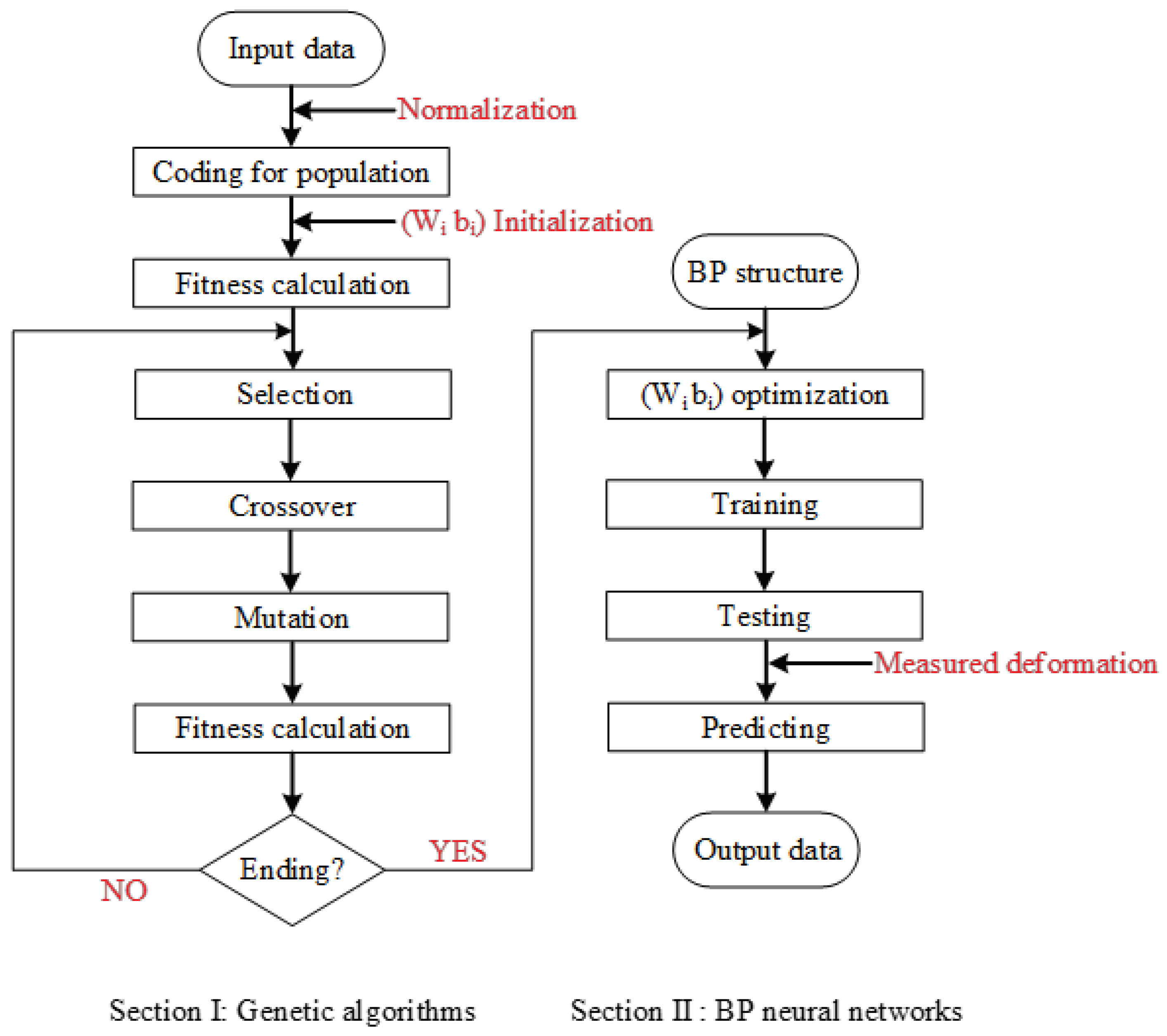
The GA-BP algorithm [
30] is applied on the deformation obtained by the field test for the inversion of creep parameters of surrounding rock. The core principle of this algorithm is to train the model on the backpropagation error to minimize error and attain high accuracy. The nonlinear mapping relationship between the input (deformation of surrounding rock) and the output (creep parameters) is established.
Figure 6 illustrates the process of parameter inversion using the GA-BP algorithm.
4.2.2. Orthogonal Test Design
Parameters in the Burgers–Mohr model are classified into two parts, namely the Burgers parameters and the Mohr–Coulomb parameters. Here, cohesion c and frictional angle
φ of the rock mass are determined using lab tests, and creep parameters
EM,
ηM,
EK, and
ηK are to be inversed. The ranges of these parameters are listed in
Table 5. A total of 100 orthogonal tests with four factors and ten levels are designed.
Table 6 shows the creep parameters in all tests.
The excavation process of the tunnel is modeled using FLAC
3D. The creep characteristics of the tunnel during excavation are not considered because of the tunnel’s rapid excavation. After the completion of tunnel excavation and support installation, the constitutive model for the surrounding rock is changed to the Burgers–Mohr model using the creep parameters of rock mass listed in
Table 4. The calculation time for creep is set as 31 days.
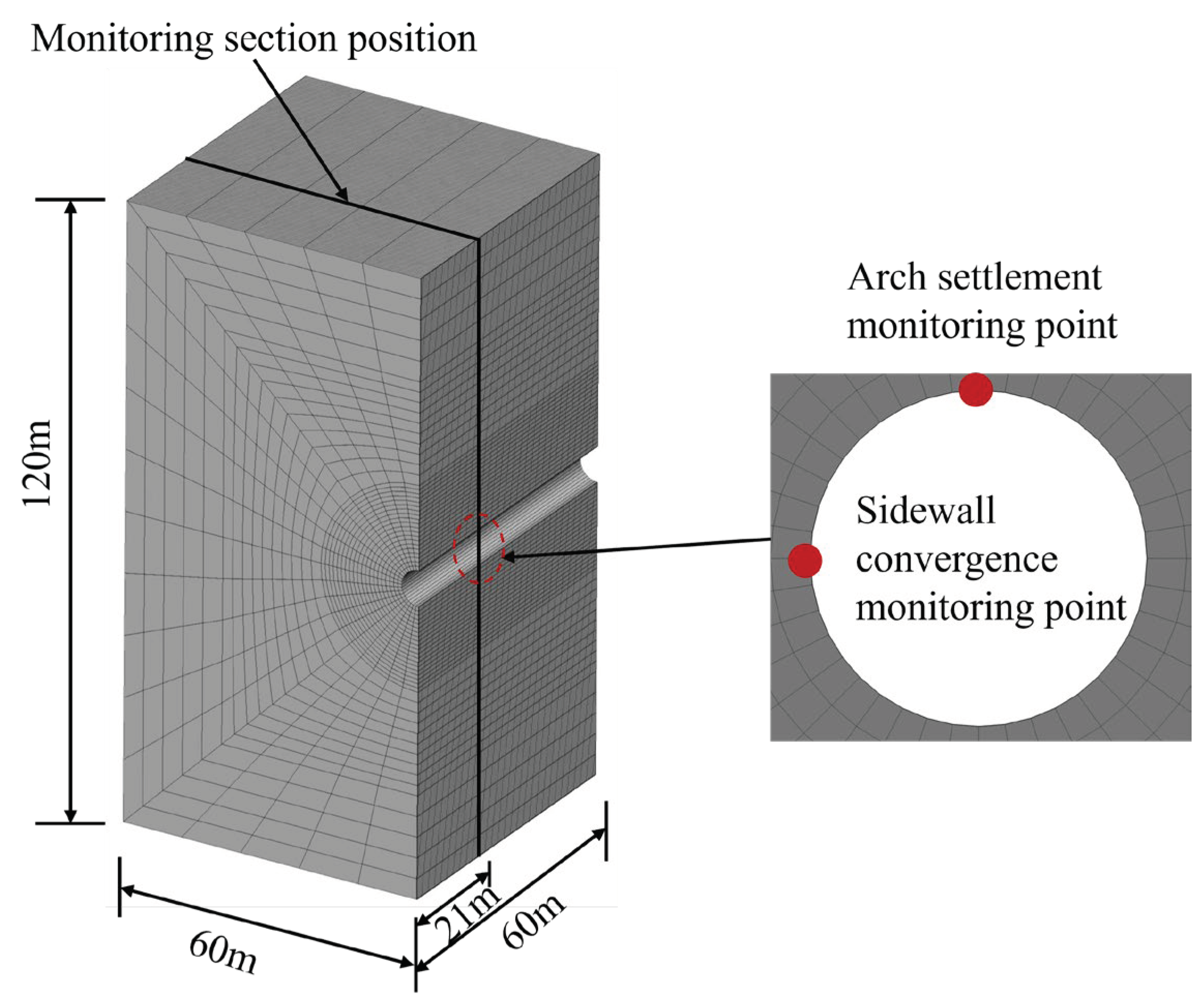
Figure 7 shows the numerical model.
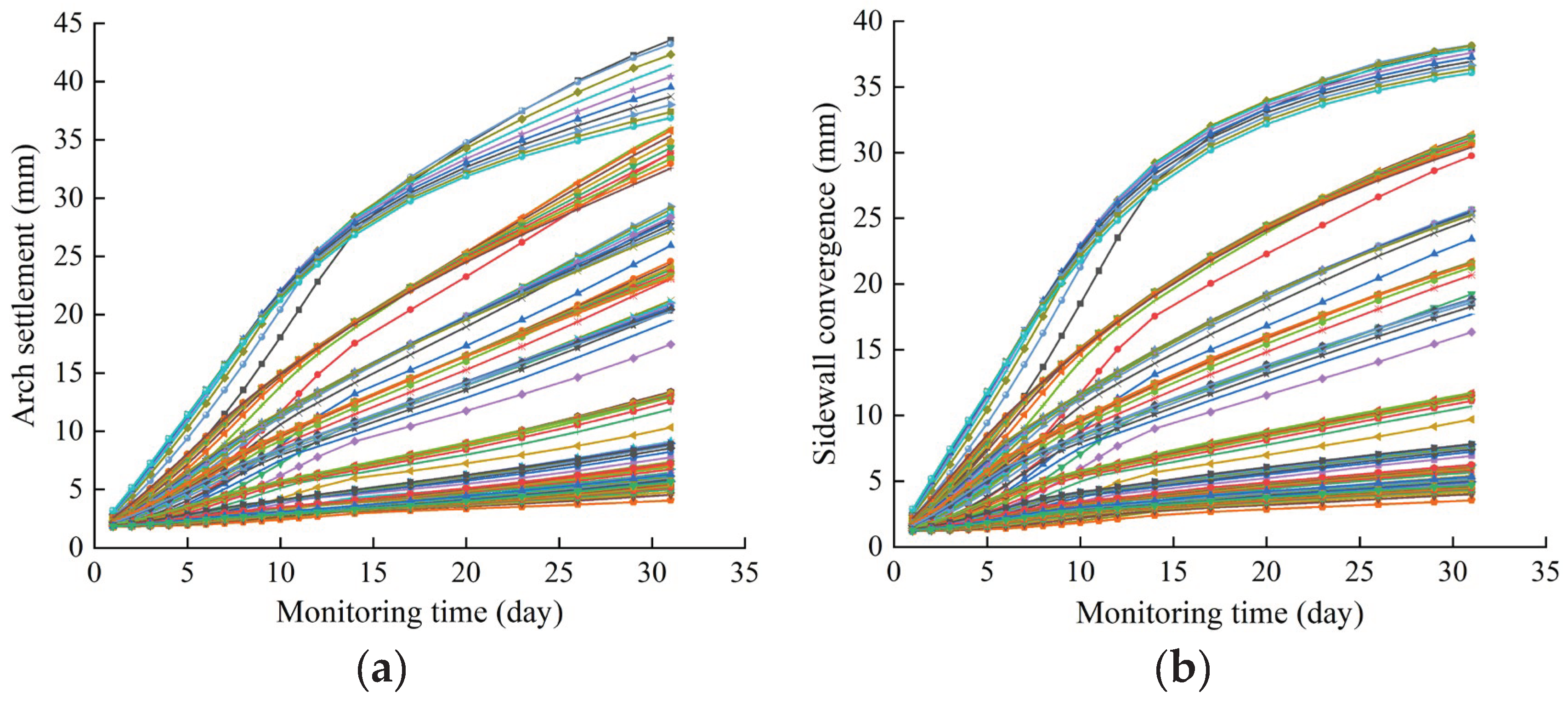
Figure 8 shows the deformation data monitored at the tunnel arch and sidewall.
4.2.3. Training and Testing of Inversion Model
The GA-BP neural network inversion model is developed with MATLAB. The 100 settlement curves of the arch or convergence curves of the sidewall shown in
Figure 8 are taken as the input data. Each curve contains 19 groups of deformation data. Therefore, the number of input neurons is 19, the number of output neurons corresponding to the creep parameters is 4, and the number of hidden layer neurons is 10. The average values of the parameters obtained from the two input methods (i.e., the settlement deformation curve of the arch and the convergence deformation curve of the sidewall) are the final inversion value.
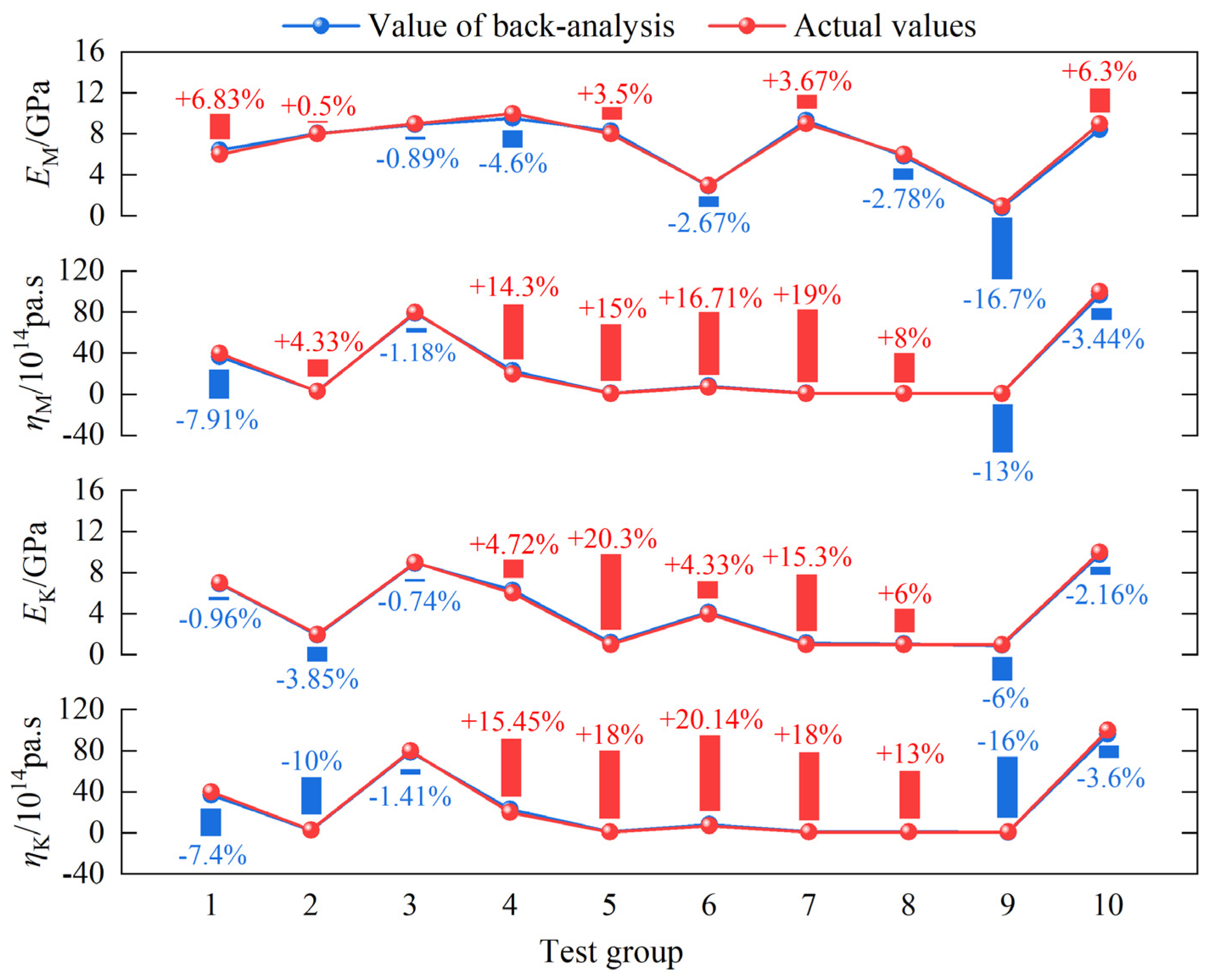
Figure 9 shows the predicted results of the test data (here "+" indicates that the inversion value is greater than the actual value, and "-" indicates that the inversion value is less than the actual value).
As observed, the inversion accuracies of shear moduli (EM and EK) are higher than those of coefficients of viscosity (ηM and ηK). The error of EM in test group 9 is 16.7% and those of EK in test groups 5 and 7 are larger than 15%; however, the errors in other test groups are all smaller than 7%. The errors of ηM and ηK in test groups 4, 5, 6, and 7 are all more than 15%. The main reason is that ηM and ηK are small, and despite the small absolute difference between the inversion value and the actual value, the relative error is considerably large. In general, the inversion accuracy of monitored data is high, and relative errors are controlled within 20%, with the majority being no more than 10%.
4.2.4. Creep Parameter Inversion Analysis Based on Monitored Data
The deformation data obtained from the field tests are used as the input for training the inversion model, and the creep parameters listed in
Table 7 are obtained. The long-term deformation is calculated using the FLAC
3D model shown in
Figure 7 to verify the feasibility of the determined creep parameters.
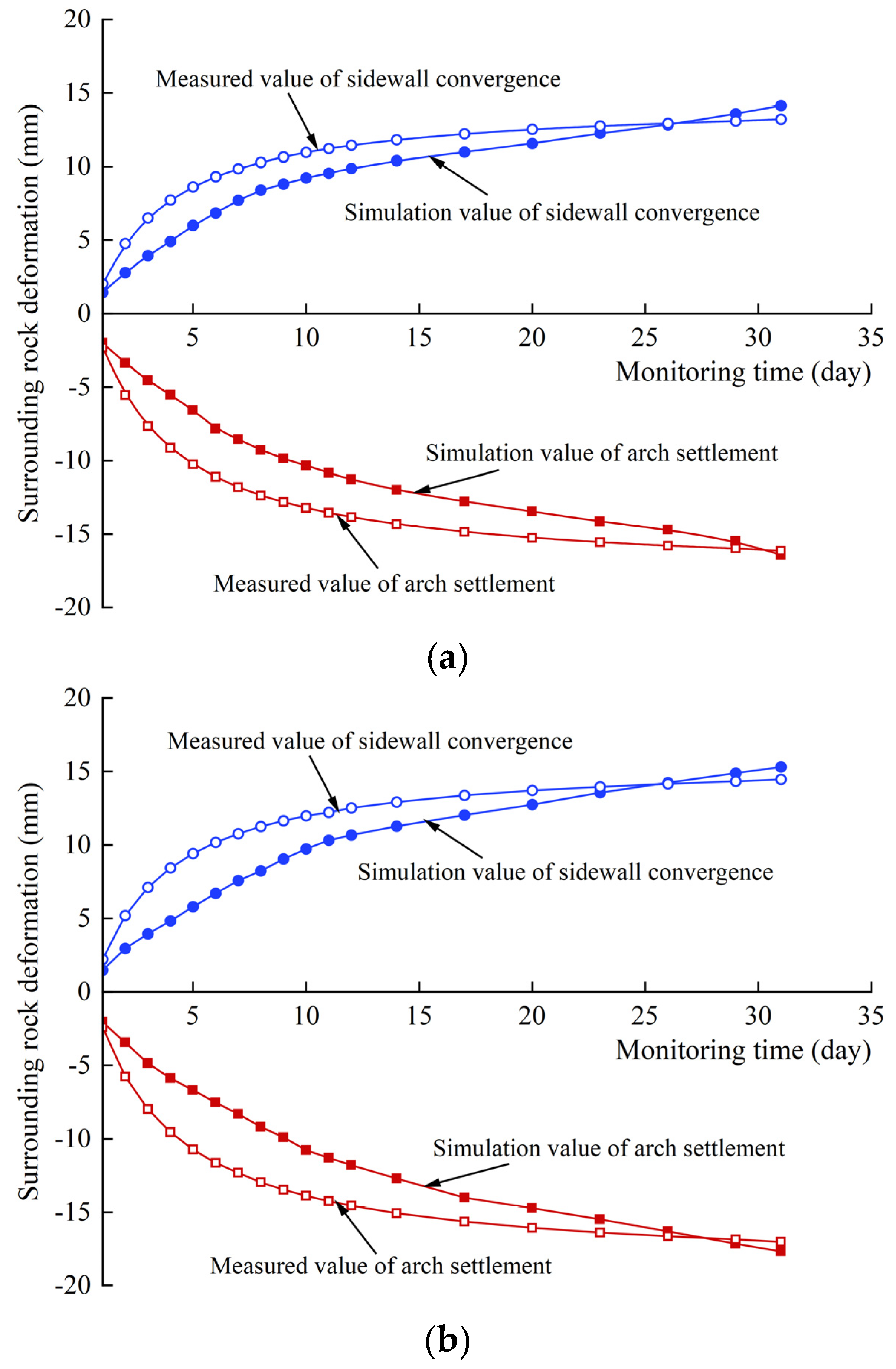
Figure 10 compares the monitoring and simulation results.
For XZ43+090 and XZ67+070, the long-term deformation and deformation trend of rock mass determined using the creep parameters of the rock mass that are obtained from the GA-BP neural network inversion model are consistent with the monitored data. This indicates that the creep parameters obtained using inversion can reflect creep deformation characteristics of surrounding rocks.
5. Long-Term Stability and Lining Safety of Surrounding Rocks in Tunnels
5.1. Long-Term Deformation of Surrounding Rocks
A numerical simulation is performed for the long-term deformation of surrounding rocks in XZ43+090 and XZ67+070 within two years after support installation using the creep parameters of the rock mass listed in
Table 5.
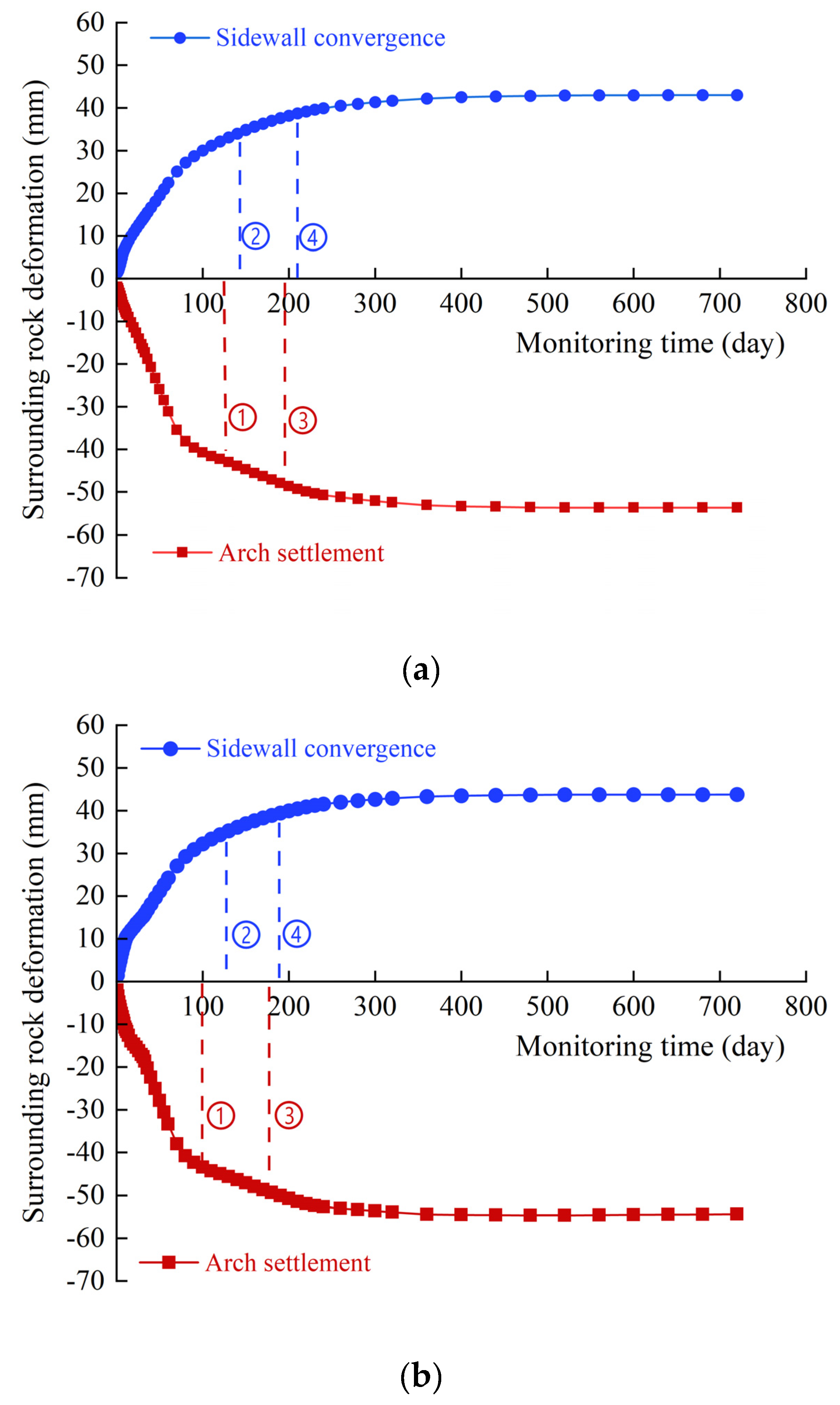
Figure 11 shows the simulation results.
After tunnel excavation, the deformation of surrounding rocks increases with time. However, the deformation rate tends to gradually reduce and finally become stable approximately 300 days after support installation. After two years, the settlement deformation of the arch in XZ43+090 is 53.64 mm and its deformation rate is less than 0.075 mm d−1; the convergence deformation of sidewall is 42.99 mm and its deformation rate is less than 0.1 mm d−1. After two years, the settlement deformation of the arch in XZ67+070 is 54.67 mm and its deformation rate is less than 0.075 mm d−1; the convergence deformation of sidewall is 43.77 mm and its deformation rate is less than 0.1 mm d−1.
5.2. Timing of Lining
According to the Technical Specifications for Construction of Highway Tunnel [
31] and results of previous research [
32,
33,
34], the timing of lining is generally determined by the deformation and deformation rate of surrounding rocks, as well as whether the deformation causes damage to the initial supporting and lining structures. The following specific principles are considered: (1) 80%–90% of the predicted total displacement is achieved; (2) the displacement deformation rate has converged and the deformation of surrounding rocks tends to be stable, the horizontal convergence rate of arch is less than 0.1–0.2 mm d
−1, or the arch settlement rate of arch is less than 0.07–0.15 mm d
−1; (3) the initial supporting surface fracture (e.g., steel arch bending and shotcrete cracking) is no longer developing, and it continues to exhibit compressive (tensile) strength; (4) during tunnel operation, the pressure on the lining does not exceed the limit value. Based on these principles, two periods of lining support can be determined—the critical period of failure of the initial supporting structure (latest timing of lining) and the critical period at which lining is damaged due to excessive pressure during long-term deformation (earliest timing of lining).
5.2.1. Latest timing of lining
The deformation of surrounding rocks and deformation rate corresponding to ①, ②, ③, and ④ in
Figure 11 are demonstrated in
Table 8. The deformation and deformation rate satisfy the requirement that the displacement should be 80%–90% of the expected total displacement and the horizontal convergence rate of tunnel is less than 0.1–0.2 mm d
−1, or the settlement rate of arch is less than 0.07–0.15 mm d
−1.
For determining the latest timing of lining, the deformation of surrounding rocks should converge, and the supporting force should not exceed the limit. The stress of rock mass during creep is simulated. The maximum tensile stress of XZ43+090 127 days after the completion of support installation is 134 kN and the maximum compressive stress of the steel arch is 210 MPa; these values are close to the ultimate levels, suggesting a great risk for the support safety. Therefore, it is not appropriate to determine the latest timing of lining based on the deformation that is 80% of the maximum deformation. When the latest timing of lining is moved forward to 110 days after completion, the maximum tensile stress of the bolt is 124.6 kN, which is 90.9% of its ultimate bearing capacity. The maximum compressive stress of steel arch is 178.2 MPa, which is 82.7% of its ultimate bearing capacity. In this case, the supporting structure plays a prominent role and is still in a safe state. The latest timing of lining for XZ43+090 is 110 days. The maximum tensile stress of the bolt 100 days after the support is installed in XZ67+070 is 128 kN, which is 93.4% of its ultimate bearing capacity. The maximum compressive stress of the steel arch is 183 MPa, which is 85.1% of its ultimate bearing capacity. It is still in a safe state. Therefore, the latest timing of lining in this section is determined to be 100 days. The deformation curves of the surrounding rocks after support installation and lining are shown in
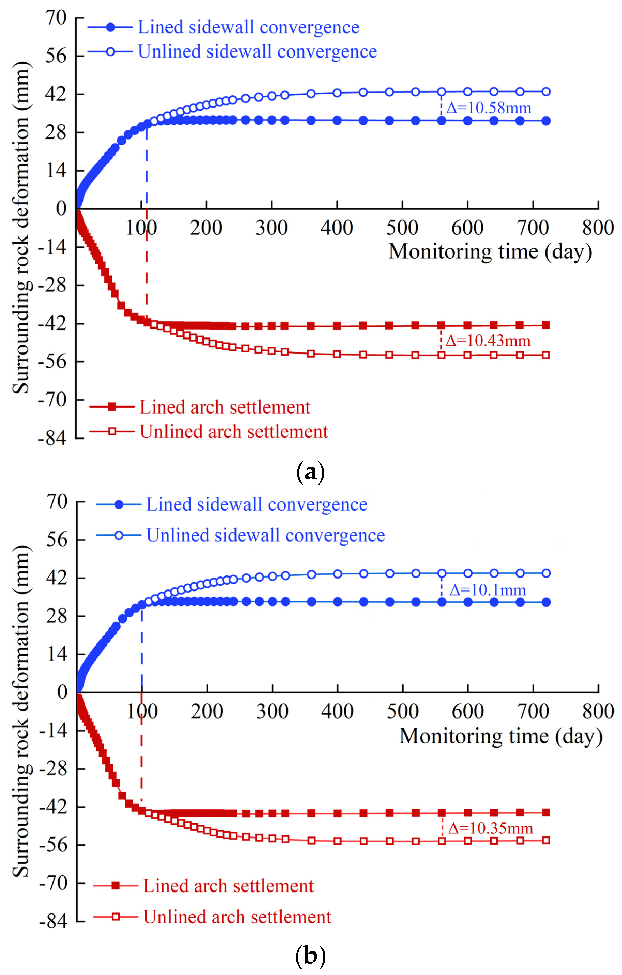
Figure 12.
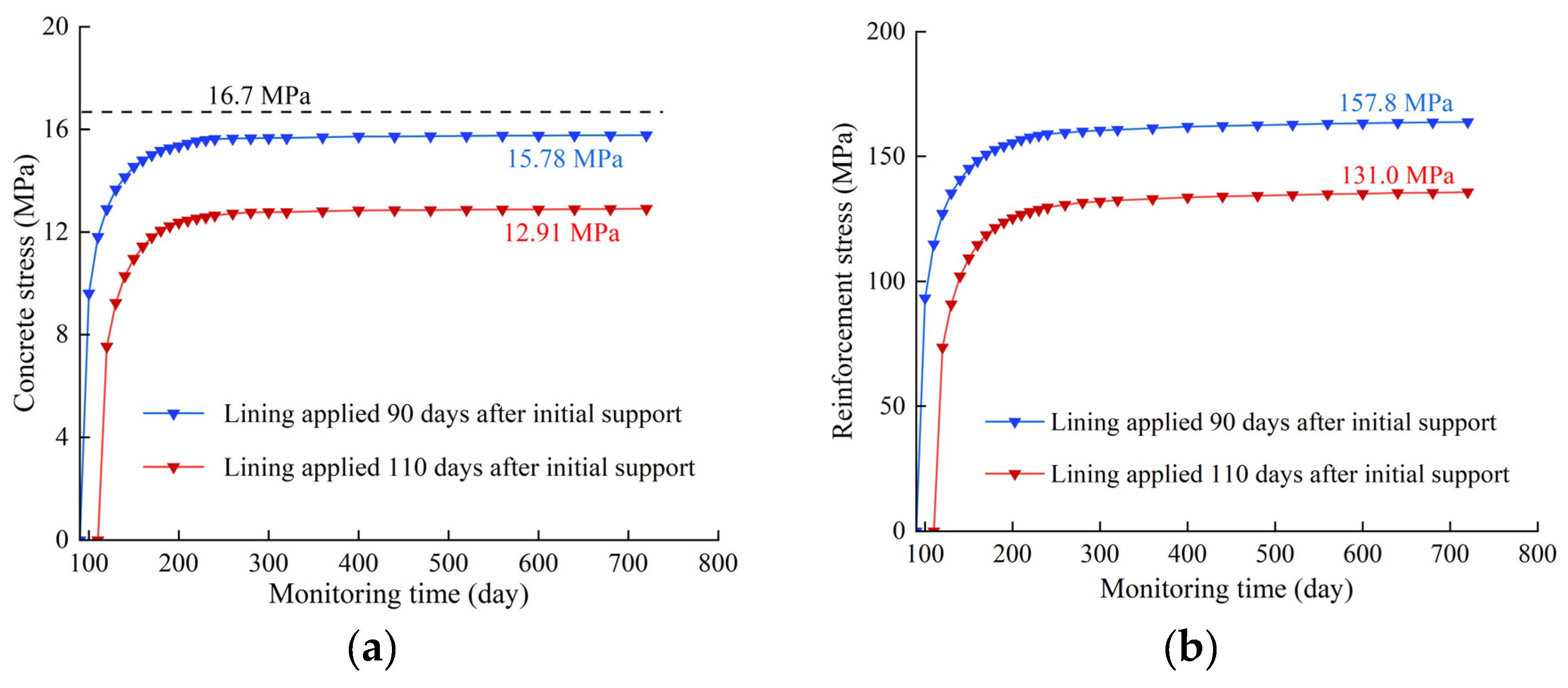
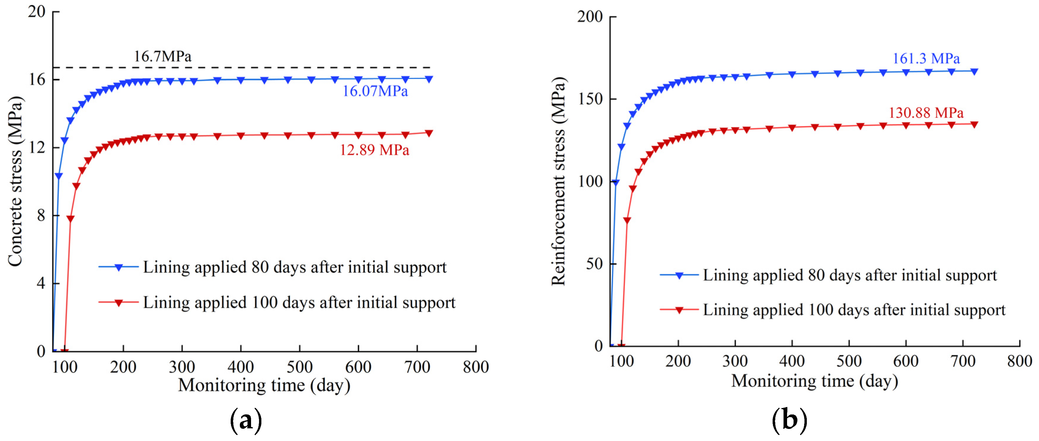
We can observe that the lining constrains the development of creep even though the creep characteristics of mudstone exist after the pouring of reinforced concrete lining. For XZ43+090 and XZ67+070, the deformation limit is 10 mm, and the surrounding rock will exert deformation pressure on the reinforced concrete lining. The long-term stress in concrete and steel of the lining is shown in
Figure 13 and
Figure 14, respectively.
For XZ43+090, when the lining is poured 110 days after the support installation, the creep effect of surrounding rocks causes the reinforced concrete lining to generate compressive stress with increasing operation time. Once the deformation of surrounding rocks is completely stable, the maximum compressive stress in the concrete lining is 12.91 MPa and that in the steel lining is 131.00 MPa. For XZ67+070, when the lining is poured 100 days after support installation, the maximum compressive stress in concrete is 12.89 MPa and that in steel is 130.88 MPa. The stresses in both concrete and steel are lower than the ultimate values. The latest timing of lining for XZ43+090 and XZ67+070 is determined as 110 days and 100 days, respectively.
5.2.2. Earliest Timing of Lining
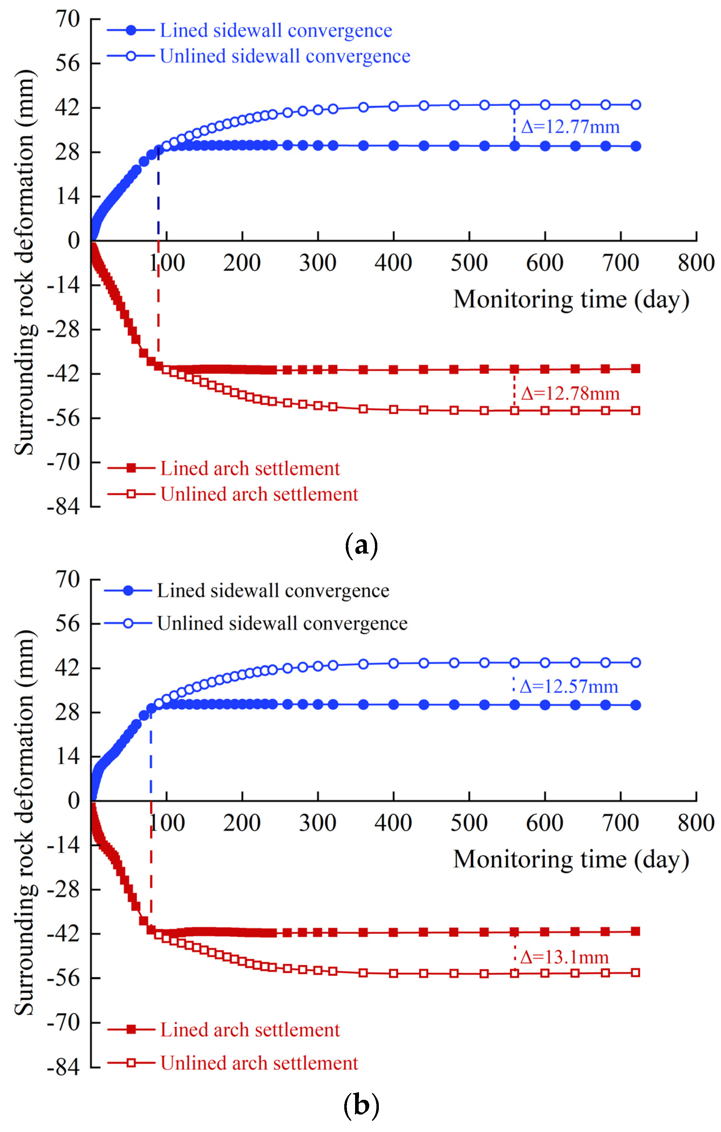
The earliest timing of lining is mainly to control the deformation load imposed on the lining by the creep deformation of surrounding rocks, thus avoiding excessive stress and damage to the lining in the later stage. Based on the calculation of lining stress after the pouring of lining, the earliest timing of lining for XZ43+090 is determined to be 90 days after support installation and that for XZ67+070 is 80 days after support installation. The forces of these two linings are shown in
Figure 13 and
Figure 14. The maximum compressive stress in concrete and steel of XZ43+090 are 15.78 and 157.80 MPa, respectively. The maximum compressive stress in concrete and steel of XZ67+070 are 16.07 and 161.30 MPa, respectively.
Figure 15 shows the deformation of surrounding rocks after the lining is poured at this time.
We can observe that the settlement deformation of the arch 90 days after the support is installed in XZ43+090 accounts for 74% of the overall deformation (deformation rate = 0.11 mm d−1), and the convergence deformation of the sidewall is 67% of the overall deformation (deformation rate = 0.13 mm d−1). The settlement deformation of the arch 80 days after the support is installed in XZ67+070 accounts for 75% of the overall deformation (deformation rate = 0.149 mm d−1), and the convergence deformation of the sidewall is 67% of the overall deformation (deformation rate = 0.159 mm d−1). The deformation rates of the arch and sidewall are within the limit.
6. Conclusions
This study conducted lab tests, a parameter inversion method, and numerical simulations on a water diversion project in Xinjiang to determine the creep characteristic models of mudstone collected from the surrounding rocks and the construction timing and safety of lining. The following conclusions can be drawn:
(1) The strain of the mudstone of the supporting work under loading at each stage can be divided into transient strain and creep strain. The mudstone exhibited decay creep under a low deviatoric stress, decelerated creep and isokinetic creep under an intermediate deviatoric stress, and steady creep under a high deviatoric stress. The Burgers model was adopted as the creep constitutive model for mudstone.
(2) The Burgers–Mohr model that considers the yield characteristics of mudstone was used to model the rock mass. To establish the GA-BP neural network inversion model, 100 orthogonal tests were performed using random creep parameters. The long-term deformation data of the arch and sidewall of the tunnel were monitored in situ, and the creep parameters of the mudstone rock mass of XZ43+090 and XZ67+070 were obtained. The creep deformation of the surrounding rock was observed to be stable 300 days after the installation of the support, after which the creep effect decreased.
(3) Based on the long-term creep deformation characteristics, the initial support, and the stress of the lining of surrounding rocks, the optimal timing of lining for XZ43+090 and XZ67+070 was determined as 90–110 and 80–100 days after support installation, respectively. Construction of the lining during these periods is ideal to meet the requirement for the deformation and deformation rate of surrounding rocks to ensure the safety of the support and lining. The results of this study can serve as a reference for similar projects in China and worldwide.
Author Contributions
Conceptualization, J.P; Formal analysis, L.L and X.W; Investigation, J.P and Y.L ; Resources, L.L and X.W; Data curation, J.P; Writing – original draft, J.P; Writing – review & editing, J.P and L.L; Supervision, L.L and X.W; Project administration, J.P and Y.L; Funding acquisition, L.L. All authors have read and agreed to the published version of the manuscript.
Funding
This work was financially supported by grants from the National Natural Science Foundation of China, China (Grant No. 52179121, 51879284), the IWHR Research & Development Support Program, China (Grant No. GE0145B012021) and State Key Laboratory of Simulations and Regulation of Water Cycle in River Basin (Grant No. SKL2022ZD05).
Institutional Review Board Statement
Not applicable.
Informed Consent Statement
Not applicable.
Data Availability Statement
All data: models, or code that support the findings of this study are available from the corresponding author upon reasonable request.
Conflicts of Interest
The authors declare that there is no conflicts of interest that may affect the research reported in this paper.
References
- Steiner, W. Tunnelling in squeezing rocks: Case histories. Rock Mech. Rock Eng. 1996, 29, 211–246. [Google Scholar] [CrossRef]
- Dalgıç, S. Tunneling in squeezing rock, the Bolu tunnel, Anatolian Motorway, Turkey. Eng. Geol. 2002, 67, 73–96. [Google Scholar] [CrossRef]
- Zhang, Z.D. Discussion and study on large deformation of tunnel in squeezing ground. Modern Tunnelling Technology 2003, 40, 5–12. [Google Scholar]
- Hoek, E.; Guevara, R. Overcoming squeezing in the Yacambú-Quibor tunnel, Venezuela. Rock Mech. Rock Eng. 2009, 42, 389–418. [Google Scholar] [CrossRef]
- Meng, L.; Li, T.; Jiang, Y.; Wang, R.; Li, Y. Characteristics and mechanisms of large deformation in the Zhegu mountain tunnel on the Sichuan–Tibet highway. Tunn. Undergr. Space Technol. 2013, 37, 157–164. [Google Scholar] [CrossRef]
- Tran Manh, H.; Sulem, J.; Subrin, D.; Billaux, D. Anisotropic time-dependent modeling of tunnel excavation in squeezing ground. Rock Mech. Rock Eng. 2015, 48, 2301–2317. [Google Scholar] [CrossRef]
- Huang, M.; Zhan, J.W.; Xu, C.S.; Jiang, S. New creep constitutive model for soft rocks and its application in the prediction of time-dependent deformation in tunnels. Int. J. Geomech. 2020, 20, 04020096. [Google Scholar] [CrossRef]
- Ito, H.; Sasajima, S. A ten year creep experiment on small rock specimens. Int. J. Rock Mech. Min. Sci. Geomechanics Abstracts 1987, 24, 113–121. [Google Scholar] [CrossRef]
- Maranini, E.; Brignoli, M. Creep behaviour of a weak rock: Experimental characterization. Int. J. Rock Mech. Min. Sci. 1999, 36, 127–138. [Google Scholar] [CrossRef]
- Sun, J. Rock rheological mechanics and its advance in engineering applications. Chinese Journal of Rock Mechanics and Engineering 2007, 26, 1081–1106. (In Chinese) [Google Scholar] [CrossRef]
- Jiang, H.F.; Hu, B.; Liu, Q.; Wang, X.G. A new visco-elasto-plastic rheological model of rock. Journal of Yangtze River Scientific Research Institute. 2014, 31, 44–48. (In Chinese) [Google Scholar] [CrossRef]
- Li, L.C.; Li, S.H.; Li, H. Time-dependent deformation of rock slopes based on long-term strength characteristics of rocks. Chinese Journal of Geotechnical Engineering. 2014, 36, 47–56. (In Chinese) [Google Scholar] [CrossRef]
- Roberts, L.A.; Buchholz, S.A.; Mellegard, K.D.; Düsterloh, U. Cyclic loading effects on the creep and dilation of salt rock. Rock Mech. Rock Eng. 2015, 48, 2581–2590. [Google Scholar] [CrossRef]
- Tang, J.; Peng, Z.B.; He, Z.M. Research on improved Burgers model based on rock mass creep test. Journal of Central South University (Science and Technology). 2017, 48, 2414–2424. [Google Scholar] [CrossRef]
- Hamza, O.; Stace, R. Creep properties of intact and fractured muddy siltstone. Int. J. Rock Mech. Min. Sci. 2018, 106, 109–116. [Google Scholar] [CrossRef]
- Zhang, Y.; Shao, J.; Xu, W.; Jia, Y. Time-dependent behavior of cataclastic rocks in a multi-loading triaxial creep test. Rock Mech. Rock Eng. 2016, 49, 3793–3803. [Google Scholar] [CrossRef]
- Eslami Andargoli, M.B.; Shahriar, K.; Ramezanzadeh, A.; Goshtasbi, K. The analysis of dates obtained from long-term creep tests to determine creep coefficients of rock salt. Bull. Eng. Geol. Environ. 2019, 78, 1617–1629. [Google Scholar] [CrossRef]
- Lyu, C.; Liu, J.; Ren, Y.; Liang, C.; Liao, Y. Study on very long-term creep tests and nonlinear creep-damage constitutive model of salt rock. Int. J. Rock Mech. Min. Sci. 2021, 146, 104873. [Google Scholar] [CrossRef]
- Kavanagh, K.T.; Clough, R.W. Finite element applications in the characterization of elastic solids. Int. J. Solids Struct. 1971, 7, 11–23. [Google Scholar] [CrossRef]
- Sakurai, S.; Takeuchi, K. Back analysis of measured displacements of tunnels. Rock Mech. Rock Eng. 1983, 16, 173–180. [Google Scholar] [CrossRef]
- Kirsten, H.A.D.; Had, K. Determination of rock mass elastic moduli by back analysis of deformation measurements. In Proceedings of the Symposium on Exploration for Rock Engineering, Johannesburg; 1976; pp. 1154–1160. [Google Scholar]
- Bertuzzi, R. Back-analysing rock mass modulus from monitoring data of two tunnels in Sydney, Australia. J. Rock Mech. Geotech. Eng. 2017, 9, 877–891. [Google Scholar] [CrossRef]
- Luo, Y.; Chen, J.; Chen, Y.; Diao, P.; Qiao, X. Longitudinal deformation profile of a tunnel in weak rock mass by using the back analysis method. Tunn. Undergr. Space Technol. 2018, 71, 478–493. [Google Scholar] [CrossRef]
- Zhuang, D.Y.; Ma, K.; Tang, C.A.; Liang, Z.Z.; Wang, K.K.; Wang, Z.W. Mechanical parameter inversion in tunnel engineering using support vector regression optimized by multi-strategy artificial fish swarm algorithm. Tunn. Undergr. Space Technol. 2019, 83, 425–436. [Google Scholar] [CrossRef]
- Zheng, G.; Zhang, W.; Zhang, W.; Zhou, H.; Yang, P. Neural network and support vector machine models for the prediction of the liquefaction-induced uplift displacement of tunnels. Underground Space 2021, 6, 126–133. [Google Scholar] [CrossRef]
- Chen, Z.J.; Kang, W.F.; Huang, J.F. On the locked in stress, creep and dilatation of rocks, and the constitutive equations. Chinese Journal of Rock Mechanics and Engineering 1991, 10, 299–312. (In Chinese) [Google Scholar]
- Yuan, H.P.; Cao, P.; Xu, W.Z.; Chen, Y.J. Visco-elastop-lastic constitutive relationship of rock and modified burgers creep model. Chinese Journal of Geotechnical Engineering 2006, 6, 796–799. (In Chinese) [Google Scholar] [CrossRef]
- Hu, K.; Feng, Q.; Li, H.; Hu, Q. Study on creep characteristics and constitutive model for thalam rock mass with fracture in tunnel. Geotech. Geol. Eng. 2018, 36, 827–834. [Google Scholar] [CrossRef]
- Yang, X.; Jiang, A.; Zheng, S. Analysis of the effect of freeze-thaw cycles and creep characteristics on slope stability. Arab. J. Geosci. 2021, 14, 1033. [Google Scholar] [CrossRef]
- Liu, L.; Ling, Y.; Wei, C. Establishment and application of a general back-analysis database for determining the mechanical parameters of surrounding rock. Arab. J. Sci. Eng. 2022, 1–9. [Google Scholar] [CrossRef]
- CCCC First Highway Engineering Group Co., Ltd. Technical specifications for construction of highway tunnel. China Communications Press: Beijing, 2009. (In Chinese) [Google Scholar]
- Paraskevopoulou, C.; Diederichs, M. Analysis of time-dependent deformation in tunnels using the Convergence-Confinement Method. Tunn. Under. Space Technol. 2018, 71, 62–80. [Google Scholar] [CrossRef]
- Panet, M.; Guenot, A. Analysis of convergence behind the face of a tunnel. Int. J. Rock Mech. Min. Sci. Geomechanics Abstracts 1982, 20, 197–204. [Google Scholar] [CrossRef]
- Pan, Y.W.; Dong, J.J. Time-dependent tunnel convergence—II. Advance rate and tunnel-support interaction. Int. J. Rock Mech. Min. Sci. Geomechanics Abstracts 1991, 28, 477–488. [Google Scholar] [CrossRef]
Figure 1.
SEM and XRD test results. (a) Micro- and meso-structures (b) Mineral composition analysis.
Figure 1.
SEM and XRD test results. (a) Micro- and meso-structures (b) Mineral composition analysis.
Figure 2.
ε–t curve. (a) σ3= 1 MPa (b) σ3 = 3 MPa (c) σ3 = 6 MPa.
Figure 2.
ε–t curve. (a) σ3= 1 MPa (b) σ3 = 3 MPa (c) σ3 = 6 MPa.
Figure 3.
ε–t curve under staged loading. (a) σ3 = 1 MPa (b) σ3 = 3 MPa (c) σ3 = 6 MPa.
Figure 3.
ε–t curve under staged loading. (a) σ3 = 1 MPa (b) σ3 = 3 MPa (c) σ3 = 6 MPa.
Figure 4.
Curve fitting results (a) General Kelvin model (b) Burgers model.
Figure 4.
Curve fitting results (a) General Kelvin model (b) Burgers model.
Figure 5.
Elements of the Burgers–Mohr Model.
Figure 5.
Elements of the Burgers–Mohr Model.
Figure 6.
Procedure of parameter inversion using the GA-BP algorithm [
30].
Figure 6.
Procedure of parameter inversion using the GA-BP algorithm [
30].
Figure 7.
Arrangement of deformation monitoring sites.
Figure 7.
Arrangement of deformation monitoring sites.
Figure 8.
Deformation monitoring curves of surrounding rocks. (a) Arch (b) Sidewall.
Figure 8.
Deformation monitoring curves of surrounding rocks. (a) Arch (b) Sidewall.
Figure 9.
Inversion results of monitored data.
Figure 9.
Inversion results of monitored data.
Figure 10.
Simulation and experimental results. (a) XZ43+090 (b) XZ67+070.
Figure 10.
Simulation and experimental results. (a) XZ43+090 (b) XZ67+070.
Figure 11.
Long-term deformation curves of surrounding rocks. (a) XZ43+090 (b) XZ67+070.
Figure 11.
Long-term deformation curves of surrounding rocks. (a) XZ43+090 (b) XZ67+070.
Figure 12.
Surrounding rock deformation characteristics. (a) XZ43+090 (b) XZ67+070.
Figure 12.
Surrounding rock deformation characteristics. (a) XZ43+090 (b) XZ67+070.
Figure 13.
Stress of the lining structure of XZ43+090. (a) Stress in concrete (b) Stress in steel.
Figure 13.
Stress of the lining structure of XZ43+090. (a) Stress in concrete (b) Stress in steel.
Figure 14.
Stress of the lining structure of XZ67+070. (a) Stress in concrete (b) Stress in steel.
Figure 14.
Stress of the lining structure of XZ67+070. (a) Stress in concrete (b) Stress in steel.
Figure 15.
Surrounding rock deformation characteristics. (a) XZ43+090 (b) XZ67+070.
Figure 15.
Surrounding rock deformation characteristics. (a) XZ43+090 (b) XZ67+070.
Table 1.
Parameters of the support material.
Table 1.
Parameters of the support material.
| Materials and Parameters |
Elastic Modulus (GPa) |
Poisson’s Ratio |
Density (kg·m-3) |
Ultimate Strength (MPa) |
| Anchor bolt (Φ22) |
200 |
0.3 |
7850 |
360 |
| Steel arch (HW150) |
206 |
0.3 |
7850 |
215 |
| Shotcrete (C30) |
28 |
0.2 |
2250 |
14.3 |
| Reinforced concrete (C35) |
30 |
0.2 |
2300 |
16.7 |
Table 2.
Mechanical parameters of rock mass.
Table 2.
Mechanical parameters of rock mass.
| Pile Number |
Elastic Modulus (GPa) |
Poisson’s Ratio |
Cohesion (MPa) |
Frictional Angle (°) |
Density (kg·m-3) |
| XZ43+090 |
4 |
0.35 |
0.3 |
33 |
2500 |
| XZ67+070 |
4 |
0.35 |
0.3 |
33 |
2500 |
Table 3.
Parameter fitting results of the general Kelvin model.
Table 3.
Parameter fitting results of the general Kelvin model.
| Deviator Stress |
EM (GP) |
EK (GPa) |
ηK (GPa·h) |
Curve Fitting Equation |
R2
|
| 12.44 MPa |
1.83 |
7.94 |
6222 |
|
0.960 |
| 14.49 MPa |
2.06 |
7.99 |
7139 |
|
0.956 |
| 16.52 MPa |
2.27 |
8.23 |
8222 |
|
0.957 |
| 17.50 MPa |
2.37 |
8.21 |
8889 |
|
0.956 |
| 18.48 MPa |
2.46 |
8.34 |
9278 |
|
0.967 |
| 19.49 MPa |
2.55 |
8.21 |
10444 |
|
0.891 |
Table 4.
Parameter fitting results of the Burgers model.
Table 4.
Parameter fitting results of the Burgers model.
| Deviator Stress |
EM (GPa) |
H (GPa·h) |
EK (GPa) |
ηK (GPa·h) |
Curve Fitting Equation |
R2
|
| 12.44 MPa |
1.87 |
15306 |
9.62 |
3556 |
|
0.981 |
| 14.49 MPa |
2.11 |
13194 |
10.12 |
3694 |
|
0.979 |
| 16.52 MPa |
2.33 |
12611 |
10.81 |
4139 |
|
0.982 |
| 17.50 MPa |
2.43 |
11694 |
11.17 |
4250 |
|
0.984 |
| 18.48 MPa |
2.54 |
11306 |
11.4 |
4278 |
|
0.985 |
| 19.49 MPa |
2.64 |
12139 |
11.48 |
4639 |
|
0.950 |
Table 5.
Parameters to be inversed and their ranges.
Table 5.
Parameters to be inversed and their ranges.
| Inversion Parameters |
EM (GP) |
ηM (Pa·s) |
EK (GP) |
ηK (Pa·s) |
| Value range |
1–10 |
1×10¹⁴–1×10¹⁶
|
1–10 |
1×10¹⁴–1×10¹⁶
|
Table 6.
Parameters in the orthogonal test.
Table 6.
Parameters in the orthogonal test.
| Test |
Creep Parameters |
| EM (Pa) |
ηM (Pa·s) |
EK (Pa) |
ηK (Pa·s) |
| 1 |
1×10⁹
|
1×10¹⁴
|
1×10⁹
|
1×10¹⁴
|
| 2 |
1×10⁹
|
3×10¹⁴
|
1×10⁹
|
3×10¹⁴
|
| 3 |
1×10⁹
|
5×10¹⁴
|
1×10⁹
|
5×10¹⁴
|
| 4 |
1×10⁹
|
7×10¹⁴
|
1×10⁹
|
7×10¹⁴
|
| 5 |
1×10⁹
|
9×10¹⁴
|
1×10⁹
|
9×10¹⁴
|
| 6 |
1×10⁹
|
2×10¹⁵
|
1×10⁹
|
2×10¹⁵
|
| 7 |
1×10⁹
|
4×10¹⁵
|
1×10⁹
|
4×10¹⁵
|
| 8 |
1×10⁹
|
6×10¹⁵
|
1×10⁹
|
6×10¹⁵
|
| 9 |
1×10⁹
|
8×10¹⁵
|
1×10⁹
|
8×10¹⁵
|
| 10 |
1×10⁹
|
1×10¹⁶
|
1×10⁹
|
1×10¹⁶
|
| … |
… |
… |
… |
… |
| 91 |
10×109
|
1×10¹⁴
|
10×109
|
1×10¹⁴
|
| 92 |
10×109
|
3×10¹⁴
|
10×109
|
3×10¹⁴
|
| 93 |
10×109
|
5×10¹⁴
|
10×109
|
5×10¹⁴
|
| 94 |
10×109
|
7×10¹⁴
|
10×109
|
7×10¹⁴
|
| 95 |
10×109
|
9×10¹⁴
|
10×109
|
9×10¹⁴
|
| 96 |
10×109
|
2×10¹⁵
|
10×109
|
2×10¹⁵
|
| 97 |
10×109
|
4×10¹⁵
|
10×109
|
4×10¹⁵
|
| 98 |
10×109
|
6×10¹⁵
|
10×109
|
6×10¹⁵
|
| 99 |
10×109
|
8×10¹⁵
|
10×109
|
8×10¹⁵
|
| 100 |
10×109
|
1×10¹⁶
|
10×109
|
1×10¹⁶
|
Table 7.
Creep parameter inversion values of surrounding rocks.
Table 7.
Creep parameter inversion values of surrounding rocks.
| Creep Parameter |
EM (GPa) |
EK (GPa) |
ηM (Pa·s) |
ηK (Pa·s) |
| XZ43+090 |
5.12 |
2.1 |
1.7×10¹⁵
|
0.95×10¹⁵
|
| XZ67+070 |
5.01 |
2.0 |
1.5×10¹⁵
|
1.0×10¹⁵
|
Table 8.
Deformation of arch and sidewall and the deformation rates.
Table 8.
Deformation of arch and sidewall and the deformation rates.
| |
Arch |
Sidewall |
| Final deforma-tion (mm) |
0.8 U |
0.9 U |
Final deforma-tion (mm) |
0.8 U |
0.9 U |
| Time (day) |
Rate (mm·d-1) |
Time (day) |
Rate (mm·d-1) |
Time (day) |
Rate (mm·d-1) |
Time (day) |
Rate (mm·d-1) |
| XZ43+090 |
53.64 |
127 |
0.078 |
195 |
0.073 |
42.99 |
145 |
0.083 |
210 |
0.05 |
| XZ67+070 |
54.67 |
100 |
0.1 |
177 |
0.071 |
43.77 |
127 |
0.092 |
189 |
0.054 |
|
Disclaimer/Publisher’s Note: The statements, opinions and data contained in all publications are solely those of the individual author(s) and contributor(s) and not of MDPI and/or the editor(s). MDPI and/or the editor(s) disclaim responsibility for any injury to people or property resulting from any ideas, methods, instructions or products referred to in the content. |
© 2024 by the authors. Licensee MDPI, Basel, Switzerland. This article is an open access article distributed under the terms and conditions of the Creative Commons Attribution (CC BY) license (http://creativecommons.org/licenses/by/4.0/).
