1. Introduction
The state of the cutting tool is a vital part in reaching the quality targets for machined components. As such, the lack of this information leads to uncertainty in manufacturing and has various consequences for the process as a whole. These consequences include a drop in product quality, unplanned downtime causing loses in productivity, and of course all the economic losses associated. During manufacturing a turning tool experiences different mechanisms of wear, these include abrasion, adhesion, diffusion, fatigue, and chemical wear [
1]. The unplanned downtime that occurs as a direct consequence of excessive tool wear was estimated to be 7 to 20 percent [
2].
With these facts in mind, it is clear that a reliable, real time Tool Condition Monitoring System is the heart of intelligent manufacturing and autonomous production lines [
3]. There are two categories of Tool Condition Monitoring systems: direct and indirect methods. With the direct methods the state of the cutting tool is evaluated visually trough an optical microscope. The method has a high degree of accuracy and gives the best evaluation of the tool condition. It has, however, serious real-time limitations as it requires the cutting process to be interrupted to analyze the tool. Further it requires specific optical equipment, that is not appropriate for the industrial environment in which these systems are to be installed. The indirect methods, despite providing a lower accuracy are much simpler and robust. They rely on correlating one or more sensor signals to the tool wear state. For this, multiple variables and detection methods can be used [
4].
The cutting force signal is one of the most reliable, as it is in direct correlation to the state of the cutting edge and is therefore very sensitive to changes in tool state [
4,
5]. In their research Li et al. [
5] introduced a force-based system, with experimental results reaching a 96.76% accuracy. Despite the excellent qualities of using the force-based approach it has some drawbacks, as obtaining these values requires specialized sensors and dynamometers. Use of these types of sensors in an industrial setting has the problems of practicality as well as cost effectiveness.
Another interesting approach is the utilization of thermography, for tool wear analysis. Brili et al. [
6] utilized the images captured by a thermal imagery camera, extracting features that correlate with the tool state. The accuracy of the developed system ranged from 96.25% to 100%. Despite the excellent accuracy of the developed system, it has similar problems as the cutting force approach, mainly in terms of cost effectiveness when implementing into an industrial setting.
Systems for industrial applications gravitate towards low-cost, robust sensors, that do not interfere with the monitored process. Rmili et al. [
7] developed a system that correlates the vibrations that are produced during machining to tool wear. The proposed method is interesting, however it has certain limitations. Namely the fact that the vibratory signals are very sensitive and influenced by many variables (environment, location of sensors, type of cutting fluid…) a lot of which cannot be kept consistent for an industrial implementation.
For an industrial implementation of a system, it is always the most practical to use the machines internal data, such as power or electric current. This allows for even easier integration and is also the most cost effective. As such a lot of research has been done in the area of utilizing these signals. Drouillet et al. [
2] used the spindles internal power sensor signal to predict the remaining useful life of the tool (RUL). Jamshidi et al. [
3] research focused on utilizing the current signal to develop an alerting system, that sends a warning before the tool wear begins to reach a critical level. Our research focuses on these same signals as the overview of the literature showed that it is a highly accessible signal that requires no additional modifications or additions to the machine, with only a slight decrease in the tool wear to signal correlation.
There exist different methods of signal analysis for the purposes of TCMs. Among those we can include conventional statistical analysis [
8], the combination of time and frequency analysis [
9], Fractal analysis [
3], as well as utilizing artificial intelligence, such as genetic algorithms [
10] and image analysis with a Convolutional Neural Network [
6].
The nature of our observed signals and end application supports the use of an artificial intelligence approach. Particularly promising, for data series analysis, are recurrent neural networks such as Long Short-Term Memory networks [
11,
13]. These networks provide the ability to shift the focus of the analysis from general statistical parameters and absolute values, allowing for the recognition of inherent patterns in the acquired signals [
11].
The tool condition monitoring concept proposed looks to also add redundancy to the LSTM network predictions. This addition in the form of a Unanimous Voting Algorithm (UVA), works to remove spontaneous errors and even further increases the classification accuracy of the TCM system.
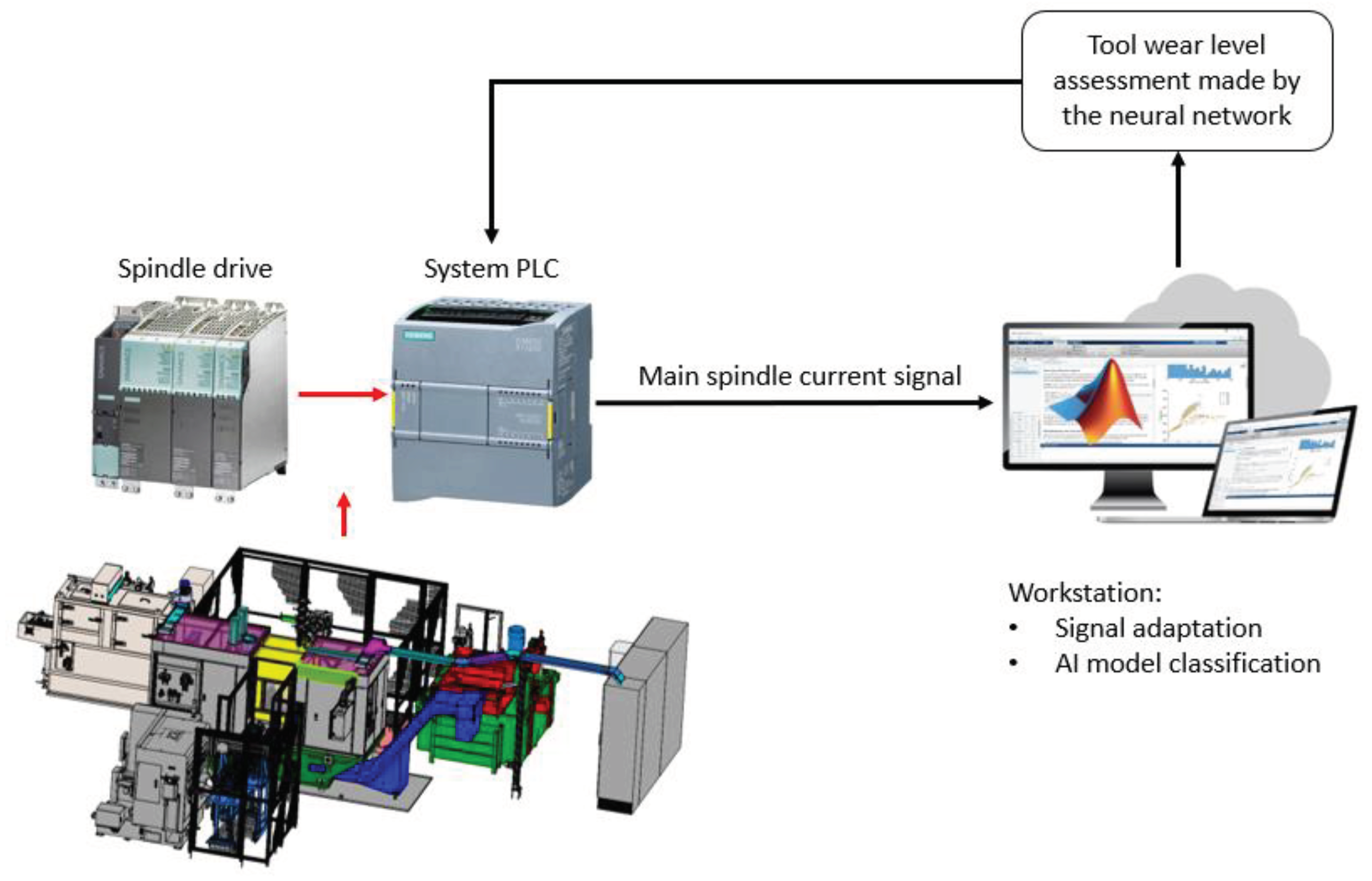
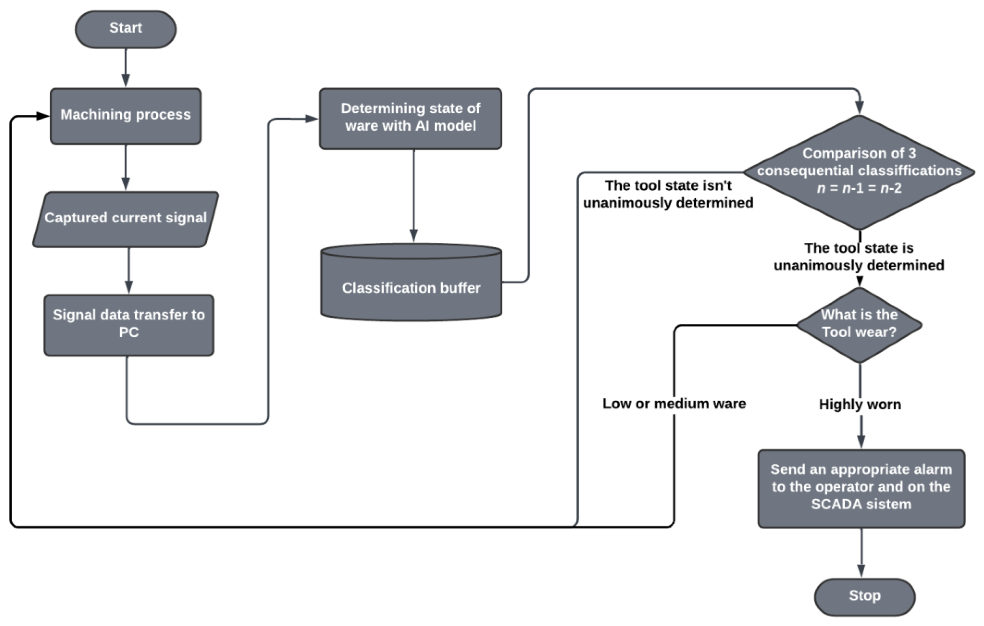
In this study an external measurement system was used to obtain the current data from the main spindle of a purpose CNC lathe. The reason for this style of measurement was to test the concept without altering the production line. The conducted research serves as a proof of concept for the use of an LSTM neural network model in combination with an UVA redundancy algorithm, as a tool condition monitoring system in an industrial setting. The innovative approach allows for real time tool monitoring with potential for complete integration into the machines system as shown in
Figure 1.
This study intends to demonstrate that a LSTM network provides a high level of reliable classification based solely on the spindle current and no other signals, which allows for an introduction of such a system to be simple and without the need for large investments.
2. Materials and Methods
The main objective of this research is to prove that the current signal recorded on the main spindle is suitable and by itself sufficient for determining the level of tool wear, when analyzed with a neural network classification model.
There is a considerable presence of noise in the current signal on the main spindle. That is the advantage of the recurrent neural network approach, as it allows to analyze not only the absolute current values, but the entire current graphed over the entire machining cycle.
The work is divided into (I) Experiment: Acquisition of current time sequences during the milling cycle; (II) Training a LSTM classification model: Sequences filtered and divided into test and training groups, training the neural network on the latter group; (III) Testing the model: The trained model was tested on previously unseen current signals; (IV) Improving functionality with an unanimous voting system algorithm (UVS): Improving the functionality by adding redundancy, further improving the models accuracy.
2.1. Experiment
The turning process is affected by several factors, as a consequence of machine properties, tool and mount type, cutting parameters and external disturbances [
6]. Despite obtaining the data from a production line in normal operation, most of these factors are held constant while the measurements were conducted. That is due to the CNC lathe being set up to conduct a single type of machining on consistent input material.
The current signal was recorded throughout the entire useful time of the tool, that being roughly 1000 manufacturing cycles.
This style of data acquisition was conducted due to several factor, chief of which was obtaining the data during normal operation of the production line. Due to limitations in obtaining data on the physical side we decided to focus on data processing to eliminate unrepresentative current sequences (expected down times, outliers…).
2.2. Categorising Tool Wear Levels
Tool wear can be analysed in several ways. Direct means, such as inspection of the tools under an optical microscope by an experienced examiner, can determine the wear level in great detail. There are also empirical methods, such as Niakis method [
12], which allow us to remove the human factor from the inspection process.
The main aim of the research being the development of an intelligent system that determines tool wear for the purposes of classifying tool wear and alerting the operator. For that reason, despite the exact ware level prediction was feasible, a more practical approach was taken by assigning the tool wear to predetermined classes based on the actions required to maintain the production line. The wear classes were determined based on previous experience and required quality standards of the final product. Currently the tools are replaced every 1000 cycles, to ensure a sufficient surface quality. This led to separating the tool useful life into 3 categories (Low, Moderate and High wear level).
As there was no secondary method to determine tool wear, buffer zones (50 machining cycles) were left between classes to protect against border cases in the training of the neural network. The breakdown of classes can be seen in
Table 1.
2.3. Current signal acquisition
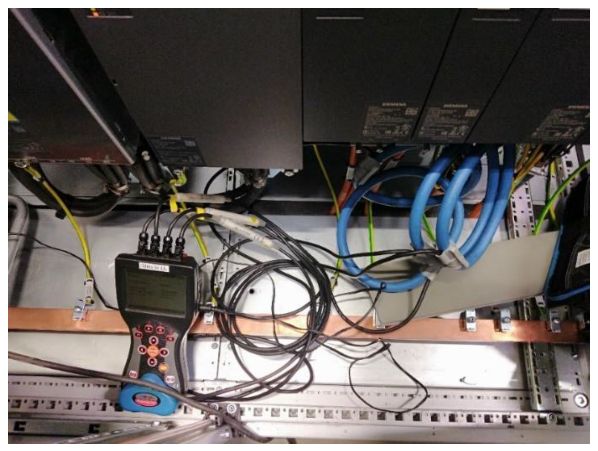
The current signal was recorded with external measurement equipment, the effective current value was monitored at the output of the spindle drive (Sinamics CU320-2 PN), as well as other electrical parameters. The measuring equipment used was an MI2792 Power Q4 power quality analyser manufactured by Metrel. The main parameters of the device are provided in
Table 2.
The measurements of the signal were conducted in 100 ms intervals and outputted as the average values of the effective current in those intervals. This signal capturing method was used to reduce the amount of noise in the recorded dataset.
2.4. Experimental setup
As mentioned, most of the machining parameters for the process we are obtaining our data from are already known (
Table 3). These parameters are held constant and ensure that all the data obtained is acquired under identical circumstances, with the only significantly varying factor being tool wear. Ensuring the model is trained on a consistent data base is paramount in generating a robust model.
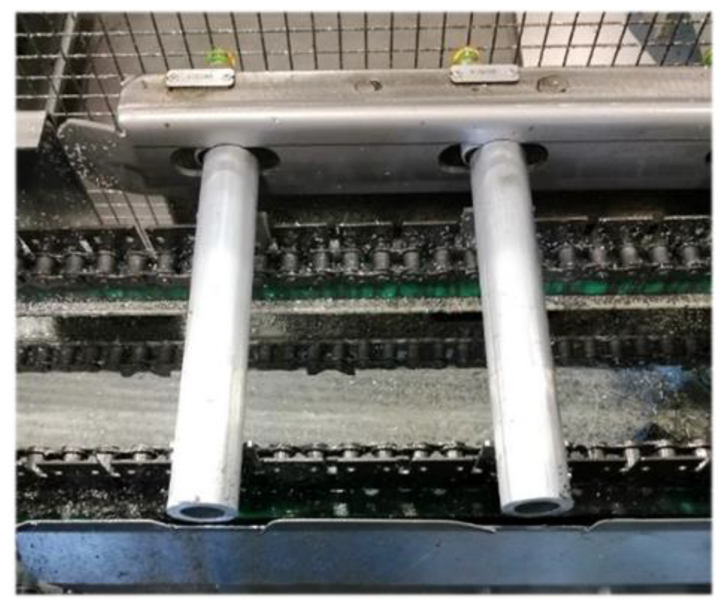
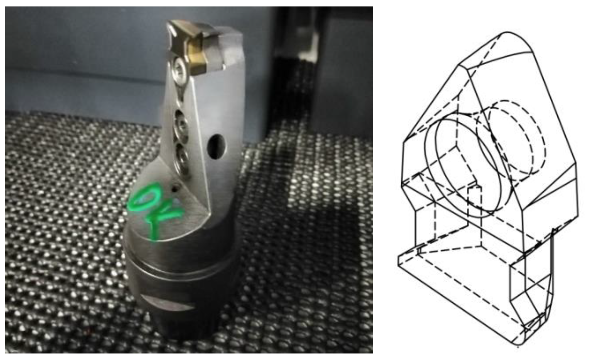
The exact workpiece material chemistry, equipment used in the experiment and the cutting tool geometry are presented in the
Table 4,
Figure 2,
Figure 3 and
Figure 4 respectively.
2.5. Long Short-Term Memory Network
The Current-Time sequences were classified with an Artificial Intelligence method. Specifically, a recurrent Long Short-Term Memory Network. This style of an artificial neural network was used because of its advantages when compared to regular feed forward neural networks. In a classical neural network, the inputs are individual data points. This style of inputting data is applicable when different variables are used simultaneously to predict tool wear.
Typically, 3 to 8 input variables are used [
14], examples include: number of revolutions, machining time, and cutting force [
15]; material of the tool, the sharpening mode, the nominal diameter, the number of revolutions, the feed rate, and the drilling length [
15], depth of cut, cutting speed, and feed to the tooth [
16]. The maximum number of inputs that were utilized successfully when using fully connected neural networks was 20 [
17]. In the case of using time sequences as Neural Network inputs, such as in this study, a fully connected neural network would have more than 100 individual inputs, each being a separate datapoint.
Such an input net size would be too expansive for a fully connected layer to process, as it would create an expansive network with a high training and execution time. Not only that, but in this method the seemingly significant parts of the current signal would have to be determined to reduce complexity, adding the risk of potentially faulty personal perception.
By using a LSTM memory network these issues can be avoided. Recursive neural networks are able to take data sequences as single inputs. This type of net also does not require the significant parts of the signal to be determined in advance as the network is trained to analyze not only the individual data points, but also the relation between them. This results in the network analyzing the shape of the signal, rather than the absolute current values.
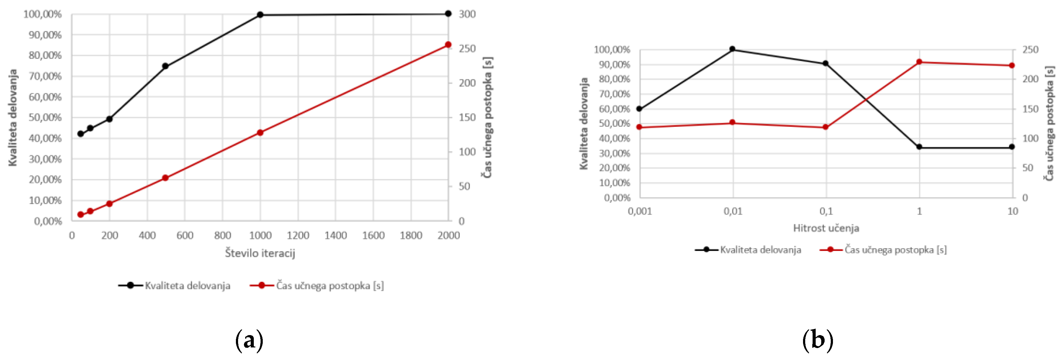
The development of LSTM is a lengthy process, however starting point structures are available. In our study some of the network’s parameters were optimized, to achieve a compromise between functionality and response time (See
Figure 5).
2.6. Unanimous voting system algorithm
To additionally reduce the occurrence of false alarms in the final monitoring application, a way to add redundancy in the analysis was required. The proposed solution is a simple voting system where the neural network model triggers the appropriate alarm based on multiple consecutive analyses, requiring them to be identical.
The unanimous voting system is a basic algorithm that compares 3 consecutive classifications that the neural network prediction model performs in real time. When the system recognizes an identical wear level three machining cycles in a row the process can be interrupted, with minimum risk of a false alarm downtime. The flowchart for the final alarming application can be seen in
Figure 6.
3. Results and Discussion
In
section 2.3 the process of acquiring the spindle current data in relation to time, as well as the distribution of that data into three categories of tool wear is presented. The entire data set was split into 2 groups for training and testing the neural network. Initially the LSTMNN was trained on a set of designated training data, and later the performance of the model was further tested with a set of testing signals – ones the network did not encounter during training. The size and distribution of the described sets is given in
Table 5.
The classification quality was evaluated using the parameters of Accuracy, Recall and Precision [
18] to ensure reliability. To visualize the results of the model’s classification attempts contingency tables were used.
The trained model was then implemented with the unanimous voting algorithm and had its accuracy tested again.
3.1. Training set results
Firstly, the training process was conducted and then all the training data classified. The resulting contingency table is depicted in
Figure 7.
A brisk inspection of figure 7 shows, that a trained network correctly determined the 1102 out of 1106 current signals after being tasked with classifying them.
The signals that resulted in false predictions were additionally analyzed to determine the error source. Inspection showed that the false prediction resulted from current data sequences that were located on the edges of the wear intervals (See
Table 1). Thus, the false predictions are mostly concentrated in the “Moderate wear” class with 2 border zones.
3.2. Training set results
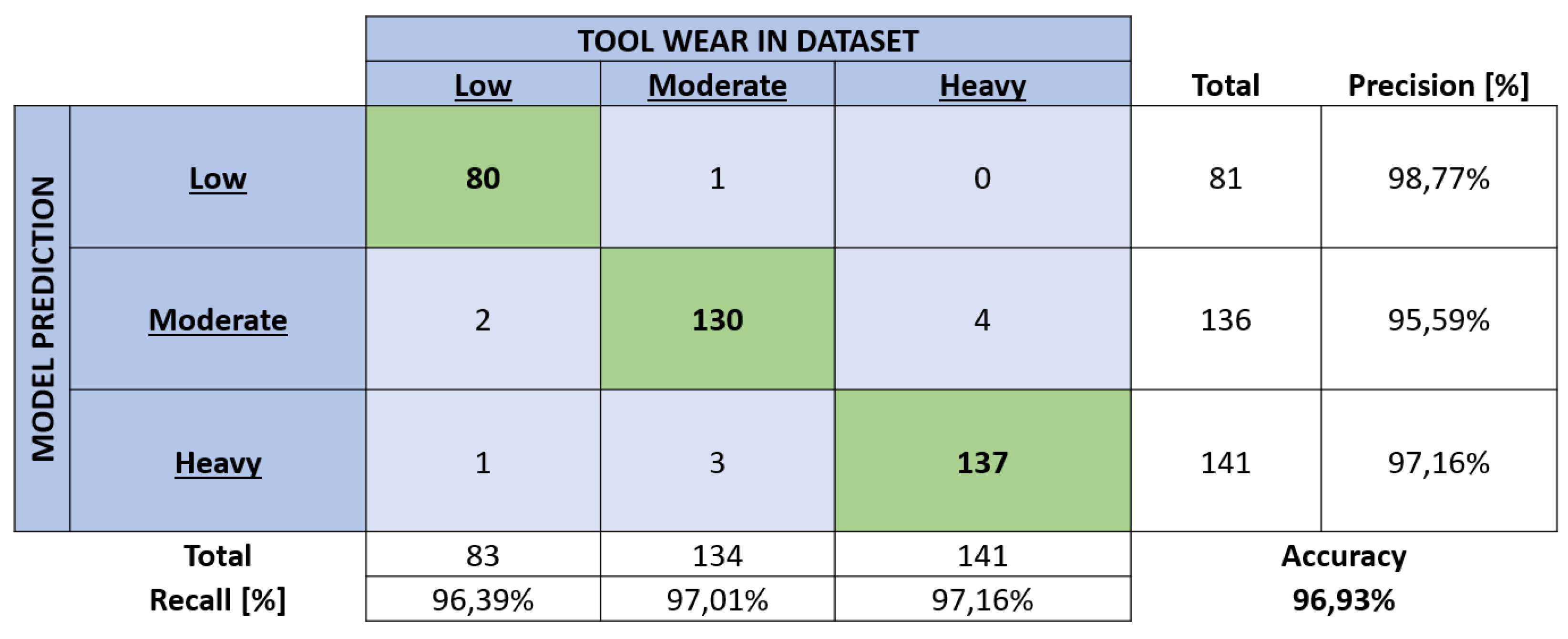
Firstly, the training process was conducted and then all the training data classified. The resulting contingency table is depicted in
Figure 8.
The change in model performance can be most easily evaluated via accuracy. A slight decrease in the said parameter can be observed between the training and testing data classification (99.64% falling to 96.93%), %), but not outside of what is expected.
The network correctly categorised 347 out of 358 current signals. When observing the error distribution, the bulk of the models’ errors are in the “Moderate wear” class, as was observed with the categorisation of training data. Additionally, all but one of the errors are one class over, with a tendency towards the higher wear class. This fact is important from a practical point of view, for the intended implementation of such a system into an industrial setting. There a random error distribution, despite high accuracy, would be unfavorable.
3.3. Unanimous voting system (UVS)
While a classification accuracy of ~97% is certainly high, additional methods were consulted to improve the reliability of the model even further. A method that was implemented is an inherent redundancy that requires the model to make three consecutive identical tool wear estimations (Figure 2.5), before resulting in an alarm or notification to the process overview interface, a more detailed description can be found in
section 2.6.
This, along with the inherent model accuracy of 96.93% increases the predictive systems accuracy to effectively 100%.
4. Discussion
The study presented addresses two main questions; Whether the condition of the cutting tool used in CNC turning can be monitored with an artificial neural network and if the current signal captured on the main spindle is a sufficient feature for that application.
The current sequences are analyzed using a Long Short-Term Memory recurrent neural network. An individual current signal data sequence consisted of a continuous 5 s spindle current measurement, coinciding with the machining cycle. The obtained sequences of data were then divided into groups based on the age of the cutting tool in terms of machining cycles. The conclusions of the research are the following:
Cutting tools were successfully divided into groups according to the tool wear.
The proposed method is confirmed to be applicable to a Tool Condition Monitoring system.
Current signal is a sufficient feature for determining tool wear.
The accuracy of the proposed system ranges from 96.93%, up to effectively 100% with additional wear prediction processing.
The results are more than encouraging compared to similar studies: 5%, 10.7%, and 22% errors for estimated tool wear for milling tools [
19]; 80% accuracy for tool breakage prediction using the Backpropagation Neural Network [
20]; comparison of predicting exact tool wear with different algorithms, where the LSTM reached an accuracy of 92.54% [
21]; a similar study classifying the tool wear rather than predicting the exact value [
22], achieved an accuracy of 95.25%, the highest when compared to RNN (85.26%) and Feedforward NN (79.35%). Proposed classification system based on LSTM Neural Network spindle current analysis is more accurate and allows for easier integration than other similar TCM systems.
5. Conclusions and Future work
The system presented is an intelligent Tool Condition Monitoring solution, showing high potential with its high accuracy and reliability, low investment cost (most necessary adaptations are digital) and high level of possible integration into the process machinery. It serves the goal of removing unpredictable decision making based on human operators experience and knowledge, in line with the ideals of Industry 4.0. The future development of this system will include improving the data acquisition, in expanding the dataset for more with more reliable measures of tool wear, as well as utilizing the machines internal sensors to record the current signal, thus aiding the industrial applicability. Further, the distribution of classes is intended to be expanded upon, adding the machining type the tool is applicable for (fine/rough), as well as other diagnostic parameters. Improving the robustness of the model is also intended, by training and testing the system with variations in the machining parameters (cutting speed, feed rate, cut depth…)
References
- W. Grzesik, “Wear development on wiper Al2O3–TiC mixed ceramic tools in hard machining of high strength steel,” Wear, vol. 266, no. 9–10, pp. 1021–1028, Apr. 2009. [CrossRef]
- C. Drouillet, J. Karandikar, C. Nath, Anne-Claire Journeaux, Mohamed El Mansori, and T. R. Kurfess, “Tool life predictions in milling using spindle power with the neural network technique,” vol. 22, pp. 161–168, Apr. 2016. [CrossRef]
- M. Jamshidi, J.-F. Chatelain, X. Rimpault, and M. Balazinski, “Tool Condition Monitoring Using Machine Tool Spindle Electric Current and Multiscale Analysis while Milling Steel Alloy,” Journal of Manufacturing and Materials Processing, vol. 6, no. 5, p. 115, Oct. 2022. [CrossRef]
- D. Yu. Pimenov, M. Kumar Gupta, L. R. R. da Silva, M. Kiran, N. Khanna, and G. M. Krolczyk, “Application of measurement systems in tool condition monitoring of Milling: A review of measurement science approach,” Measurement, vol. 199, p. 111503, Aug. 2022. [CrossRef]
- N. Li, Y. Chen, D. Kong, and S. Tan, “Force-based tool condition monitoring for turning process using v-support vector regression,” The International Journal of Advanced Manufacturing Technology, vol. 91, no. 1–4, pp. 351–361, Nov. 2016. [CrossRef]
- N. Brili, M. Ficko, and S. Klančnik, “Tool Condition Monitoring of the Cutting Capability of a Turning Tool Based on Thermography,” Sensors, vol. 21, no. 19, p. 6687, Oct. 2021. [CrossRef]
- W. Rmili, A. Ouahabi, R. Serra, and R. Leroy, “An automatic system based on vibratory analysis for cutting tool wear monitoring,” Measurement, vol. 77, pp. 117–123, Jan. 2016. [CrossRef]
- H. Arslan, A. Osman Er, S. Orhan, and E. Aslan, “Tool Condition Monitoring in Turning Using Statistical Parameters of Vibration Signal,” The International Journal of Acoustics and Vibration, vol. 21, no. 4, Dec. 2016. [CrossRef]
- Y. J. Choi, M. S. Park, and C. N. Chu, “Prediction of drill failure using features extraction in time and frequency domains of feed motor current,” International Journal of Machine Tools and Manufacture, vol. 48, no. 1, pp. 29–39, Jan. 2008. [CrossRef]
- X. Liao, G. Zhou, Z. Zhang, J. Lu, and J. Ma, “Tool wear state recognition based on GWO–SVM with feature selection of genetic algorithm,” The International Journal of Advanced Manufacturing Technology, vol. 104, no. 1–4, pp. 1051–1063, Jun. 2019. [CrossRef]
- Y.-W. Chan, T.-C. Kang, C.-T. Yang, C.-H. Chang, S.-M. Huang, and Y.-T. Tsai, “Tool wear prediction using convolutional bidirectional LSTM networks,” The Journal of Supercomputing, Jun. 2021. [CrossRef]
- Farbod Akhavan Niaki and L. Mears, “A comprehensive study on the effects of tool wear on surface roughness, dimensional integrity and residual stress in turning IN718 hard-to-machine alloy,” Journal of Manufacturing Processes, vol. 30, pp. 268–280, Dec. 2017. [CrossRef]
- H. Sun, “Optimizing Manufacturing Scheduling with Genetic Algorithm and LSTM Neural Networks,”, International Journal of Simulation Modelling, vol. 22, no. 3, pp. 508-519, Sep. 2023. [CrossRef]
- F. J. Pontes, J. J. Ferreira, Messias Borges Silva, A. Paulo, and Pedro Paulo Balestrassi, “Artificial neural networks for machining processes surface roughness modeling,” The International Journal of Advanced Manufacturing Technology, vol. 49, no. 9–12, pp. 879–902, Aug. 2010. [CrossRef]
- O. Spaic, Z. Krivokapic, and D. Kramar, “Development of family of artificial neural networks for the prediction of cutting tool condition,” Advances in Production Engineering & Management, vol. 15, no. 2, pp. 164–178, Jun. 2020. [CrossRef]
- B. Savkovic, P. Kovac, D. Rodic, B. Strbac, and S. Klancnik, “Comparison of artificial neural network, fuzzy logic and genetic algorithm for cutting temperature and surface roughness prediction during the face milling process,” Advances in Production Engineering & Management, vol. 15, no. 2, pp. 137–150, Jun. 2020. [CrossRef]
- A. Gouarir, G. Martínez-Arellano, G. Terrazas, P. Benardos, and S. Ratchev, “In-process Tool Wear Prediction System Based on Machine Learning Techniques and Force Analysis,” Procedia CIRP, vol. 77, pp. 501–504, Jan. 2018. [CrossRef]
- N. Brili, M. Ficko, and S. Klančnik, “Automatic Identification of Tool Wear Based on Thermography and a Convolutional Neural Network during the Turning Process,” Sensors, vol. 21, no. 5, p. 1917, Mar. 2021. [CrossRef]
- Y. Chi, W. Dai, Z. Lu, M. Wang, and Y. Zhao, “Real-Time Estimation for Cutting Tool Wear Based on Modal Analysis of Monitored Signals,” Applied Sciences, vol. 8, no. 5, p. 708, May 2018. [CrossRef]
- G. Li, X. Yang, D. Chen, A. Song, Y. Fang, and J. Zhou, “Tool breakage detection using deep learning,” in IEEE, 2018, pp. 37–42. [CrossRef]
- W. Cai, W. Zhang, X. Hu, and Y. Liu, “A hybrid information model based on long short-term memory network for tool condition monitoring,” Journal of Intelligent Manufacturing, vol. 31, no. 6, pp. 1497–1510, Jan. 2020. [CrossRef]
- Z. Tao, Q. An, G. Liu, and M. Chen, “A novel method for tool condition monitoring based on long short-term memory and hidden Markov model hybrid framework in high-speed milling Ti-6Al-4V,” The International Journal of Advanced Manufacturing Technology, vol. 105, no. 7–8, pp. 3165–3182, Nov. 2019. [CrossRef]
|
Disclaimer/Publisher’s Note: The statements, opinions and data contained in all publications are solely those of the individual author(s) and contributor(s) and not of MDPI and/or the editor(s). MDPI and/or the editor(s) disclaim responsibility for any injury to people or property resulting from any ideas, methods, instructions or products referred to in the content. |
© 2024 by the authors. Licensee MDPI, Basel, Switzerland. This article is an open access article distributed under the terms and conditions of the Creative Commons Attribution (CC BY) license (http://creativecommons.org/licenses/by/4.0/).
