1. Introduction
To successfully deal with the trend of combating climate change as laid out in the recommendations of the Paris (COP21 [
1]) and Glasgow (COP26 [
2]) Climate Agreements, propulsion technologies have to be capable of achieving major CO
2 reductions in increasingly shorter time frames [
3]. In order to achieve this ambitious goal, the use of electric powertrains powered by batteries is not only essential, but also serves as the primary focus for research conducted by academic and industrial organizations. Nevertheless, this technology is incapable of fulfilling all of the objectives for individual transportation, ecological accountability, and feasibility. As a result, internal combustion engines (ICE) powered by non-fossil hydrocarbons and hydrogen (H
2) will still play a significant role in future [
4,
5]. A comprehensive reviews of the positive and negative aspects of various alternative fuels, taking into account the current state of scientific and technological development as well as the needs of modern society, show that hydrogen is one of the most promising fuels — a gas with both good energy and environmental performance, as well as sufficient thermodynamic and technical compatibility with existing combustion engines. The concept of using hydrogen as a car fuel isn’t new. There are several papers [6-11] that address various issues of utilizing hydrogen in internal combustion engines (ICEs). These publications are primarily concerned with the importance of using hydrogen, as well as the challenges of acquiring hydrogen through different methods, and its impact on the fuel quality, energy storage and environmental aspects.
In terms of engine performance, employing hydrogen as a gaseous fuel has several advantages over liquid fuels like diesel and gasoline, such as easier cold start, lower emissions of pollutants and lesser contamination of lubricating oil [
12,
13]. Another advantage is that hydrogen may be produced from both renewable and nonrenewable sources, such as coal, biomass, water, and natural gas, using technologies such as gasification, electrolysis, and steam reforming. In general, hydrogen possesses various qualities that are very desirable for improving engine in-cylinder combustion and consequently engine efficiency. Examples of those properties are high flame propagation speed, heating value, diffusivity, and short quenching distance [
14]. Furthermore, when used in ICEs, hydrogen outperforms all other fossil fuels in terms of emissions, combustion stability, and leanness limit. Hydrogen, being a non-toxic and carbon-free gas, also doesn’t contribute to emissions of unburned hydrocarbon (HC) and carbon oxides, resulting in significant pollution reductions [
15]. The H
2 fueled ICE (H
2ICE) is the sole option for keeping the ICEs in future production because they not produce any tank-to-wheel CO
2 emissions at the tailpipe. Additionally, unlike fuel cell powertrains, H
2ICEs can be fueled with non-purified hydrogen, resulting in a considerably lower cost of hydrogen fuel. H
2ICEs can also make use of current advanced engine and combustion control technologies, such as direct injection [
16], Miller cycle [
17], lean/diluted combustion [
18], pre-chamber ignition [
19], etc. However, the maximum engine load with hydrogen operation is restricted by pre-ignition and autoignition. If not controlled, they can develop into more serious knocks, which can cause irreversible damage to engine components [
20]. Typically, engine peak power output is reduced by 35-50% because of to knock, which restrict the overall equivalence ratio to values from 0.6 to 0.8 [
21]. In addition, engine heat losses, aided by the short quenching distance of hydrogen, rise overproportionally during high equivalence ratio operation, reaching up to 45% of the total fuel heating value [
22] significantly restricting engine efficiency and durability.
In contrast to conventionally fuelled engines, hydrogen-gasoline or hydrogen- diesel blend engines can achieve reduced harmful emissions and improved fuel efficiency [
23,
24] without requiring extensive engine modifications. In general, converting an ordinary gasoline engine to hydrogen-gasoline requires installing a hydrogen injection and storage systems: Hydrogen can be stored in hydrogen tanks or supplied by the onboard hydrogen generator, which is typically delivered to the hydrogen injectors via a stainless steel hydrogen supply system. Furthermore, to successfully carry out hydrogen injection, the engine’s electronic control unit software must be appropriately updated. Thus, hydrogen blending is a possible option to improve engine performance in the near future. Because of its distinct qualities, hydrogen is more suited for usage in spark-ignition (SI) engines as opposed to compression-ignition (CI) engines [
25]. According to [
26] , adding hydrogen to the gasoline-ethanol blend boosted the combustion process and combustion efficiency, therefore eliminating the detrimental effect of ethanol on thermal efficiency. Increased hydrogen percentages resulted in much lower CO, HC, and CO
2 emissions. However, it was also shown that increasing the hydrogen fraction in the blend increases NO
x levels. In [
27] it was shown that the use of hydrogen in SI engines along with a passive prechamber ignition system gives significant benefits in the main chamber combustion process by improving the thermo-chemical characteristics of the mixture, boosting flame speed, and improving flame structure.
Modeling of these phenomena has gotten increasingly harder. It is necessary to integrate fluid dynamics, heat transport, thermodynamics, and chemical kinetics at different degrees of complexity in order to forecast engine operating parameters, combustion, and emissions. Zero-dimensional models are the most basic of them as they don’t need all the details of combustion process. This makes this particular type of combustion modeling simpler to do, but it may also lead to decreased precision and reliability [
28]. The Wiebe function is one method that is frequently used in engine combustion models to calculate the mass fraction burnt [
29]. The range of the Wiebe function’s S-shaped curve is from zero, which indicates the beginning of combustion, to one, which indicates the conclusion of combustion. Depending on the intensity of charge motion, engine operating state and designating shape factor which influences the shape of mass fraction burnt, the function’s form varies with a representing efficiency factor. A double-Wiebe function combustion model was developed in [
30] to study the combustion characteristics of a dual-fuel engine. They claimed that there is a good correlation between the predicted function results and experimental findings. It is demonstrated in [
31] that a triple-Wiebe function can accurately reflect every stage of dual-fuel combustion for both diesel-only operation and dual-fuel operation. After completing an in-depth literature analysis of the gasoline-hydrogen blend, it was evident that investigation of the most influential parameters on engine characteristics is necessary.
This study delves into the effects of hydrogen addition to gasoline in a four-stroke engine through a detailed thermodynamic analysis using a model based on the two-zone Wiebe function. It evaluates the engine’s performance, emissions, and efficiency with various hydrogen blends, providing insights into the thermodynamic behavior of these blends and their potential advantages. The research encompasses a broad range of air-to-fuel ratios, compression ratios, and hydrogen concentration levels, offering a comprehensive assessment of hydrogen’s impact on combustion efficiency, power output, and emission profiles on the complete engine operating range, with a particular focus on predicting NOx emissions, a significant environmental concern with internal combustion engines.
2. Methodology
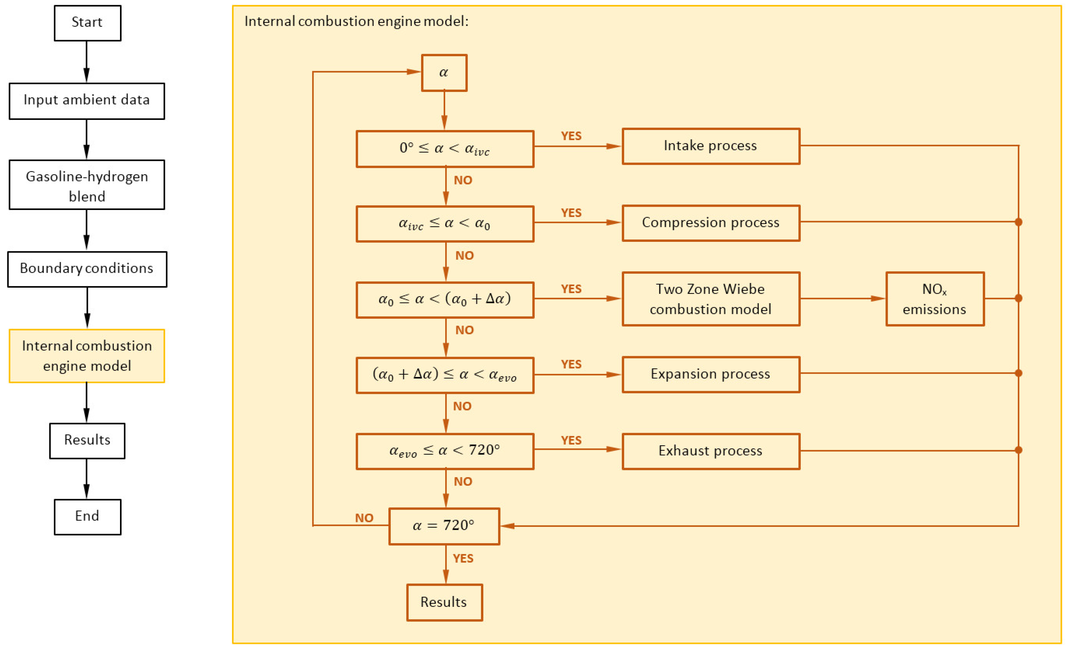
The study in this paper was conducted using an in-house MATLAB model of a four-stroke internal combustion engine. The model was specifically designed to enable dual fuel operation, using hydrogen and gasoline as fuels, and to provide an in-depth thermodynamic analysis of the engine’s dynamics, with a particular focus on the complexities of the combustion process, emission characteristics, and improvements in efficiency resulting from the incorporation of hydrogen into the gasoline-air mixture. Schematic representation of model structure is shown in
Figure 1.
The presented model integrates many interconnected components that replicate the actual processes occurring within the engine. The air intake system incorporates a boundary condition that represents the surrounding air, together with an air filter model that accurately calculates the pressure drop, closely resembling real-world circumstances. The throttle and exhaust restriction component control the flow of both air and exhaust, simulating various pressure drops in the intake and exhaust manifolds and tailpipe.
2.1. Fuel System Model
The fuel system is designed with two separate storage units for hydrogen and gasoline, enabling precise control over blend ratios. The central components responsible for controlling and monitoring the model’s operations are the common rail model and control unit. These oversee the fuel injection and ignition timing processes.
The common rail model is an essential part of modern direct injection systems. The high-pressure fuel reservoir ensures a constant supply of fuel at the right pressure for injection into the engine’s cylinders. A calculation is performed to determine the pressure within the rail for the control system. The model contains a detailed computation of the mass flow rate entering and exiting the rail in order to precisely assess the pressure dynamics. The equation for the mass flow rate of rail pressure takes into account variables such as fuel density, the size of the intake and outlet orifices and the pressure differential across these orifices and can be fully seen in equation (1).
In equation (1)
is pressure inside rail,
is bulk modulus for the working fluid,
is rail volume,
is density of the fluid inside rail,
and
are mass flows through pump and injector.
Injection mass flow is determined by considering the area of the nozzle hole and the velocity of injection. The velocity is determined by applying the Bernoulli equation. The derived equation contains the fuel density and the discharge coefficient. The discharge coefficient estimates the amount of frictional losses occurring across the entire injection system. The flow through an orifice, assuming the fluid is incompressible, can be described by the following equation:
where
is area of the nozzle holes,
is discharge coefficient and
is pressure inside cylinder.
2.2. Control Unit Model
The control unit has been designed to compute the fuelling multipliers for gasoline and hydrogen in a dual-fueled internal combustion engine. It considers operating characteristics such the engine’s rotational speed, the volumetric air flow rate, the mass ratio of hydrogen to gasoline (
, and the intended air-to-fuel equivalence ratio (
). The computed multipliers, one for gasoline (
and one for hydrogen (
, establish the necessary quantities of each fuel to produce combustion under various conditions.
In cases when the engine’s rotational speed is less than 700 RPM, the gasoline multiplier is calculated using a specific equation that assumes a constant stoichiometric ratio for gasoline, without taking into account the hydrogen content or the air to fuel equivalence ratio. This was done to ensure that idle control remained as basic as possible. On the other hand, when the RPM is 700 or higher, the function uses a more dynamic approach to calculate the multipliers for both gasoline and hydrogen which can be seen in equations (4)
These calculations modify the fuelling rates by taking into account the current engine speed, the blended stoichiometric ratio, and the target air to fuel equivalence ratio. This approach guarantees that the fuel blend achieves optimal combustion by dynamically adjusting to the engine’s operational conditions. The gasoline multiplier is calculated initially, taking into account the quantity of gasoline in the blend. Consequently, the hydrogen multiplier is derived by calculating the gasoline multiplier and then modifying it based on the ratio of hydrogen to gasoline mass. This approach provides for fine control over the fuelling of both gasoline and hydrogen, supporting efficient combustion throughout a range of operational situations.
2.3. Combustion Model
At the model’s core is the engine block where combustion is initiated, linked to the air intake and exhaust systems. The Wiebe model is a method used to simulate the combustion process within an internal combustion engine, offering a simplified approach that hinges on specifying the rate of heat release based on the engine’s crank angle rather than time. This method efficiently translates cylinder pressure data into a combustion heat release rate by plotting it against crank angle degrees, which can be readily obtained from engine tests and literature search. The model employs what’s known as the Wiebe function, a mathematical representation that captures the characteristics of an engine’s heat release. Parameters within this function, including the mass fraction burned and crank angle, along with shape parameters, dictate the form of the heat release curve. Equation for rate of heat release calculated with Wiebe function can be seen in equation (5):
where
is fuel heat input,
is Wiebe parameter for combustion completeness,
is combustion duration, m is shape parameter,
is crank angle and
is start of combustion. The integral of this function over the crank angle gives the cumulative mass of fuel burned since combustion started, providing a continuous picture of the combustion process. To add complexity and enhance the realism of the simulation, the Wiebe Two Zone model is used in this article which divides the combustion chamber into two zones—burned and unburned. Mathematical expressions in this model ensure the conservation of mass and volume between the two zones, reflecting the physics of the combustion process more closely. In a single-zone analysis of combustion, the energy equation considers only the overall state of the cylinder, which averages out the temperature and the composition of the species and applies the perfect gas law to those averaged properties of the gas mixture. By contrast, the two-zone model divides the cylinder’s contents into burned and unburned zones, applying the perfect gas law separately to each zone. These zones display marked differences in temperature and species composition. The variable nature of gas properties such as the gas constant (R) and specific heats (c
v, c
p), which depend on temperature and species composition, means that the amount of fuel needed to achieve a particular pressure target will differ between single-zone and two-zone approaches during combustion. In the case of uneven combustion, such as that found in direct injection engines, the two-zone model requires an additional assumption. The local air to fuel ratio changes over the course of the combustion, starting rich and becoming leaner, which affects the expansion rate of the burned zone and its temperature trajectory. In this article the air to fuel ratio is modeled to increase linearly in proportion to the ratio of fuel burned.
2.4. NOx Model
One more thing which needs more detailing is modeling of NOx reactions. The NOx formation model implemented in this model is based on well-known Zeldovich mechanism, which is a kinetic scheme for describing how NOx is formed during high-temperature combustion.
In
Table 1. six reactions (R1 to R6) are shown for each reaction along with their rate constants (k
0) and temperature exponents (a), as well as the reference temperatures (T
A) at which these constants are valid. Each reaction rate (r) is expressed as a product of the concentration of reactants, the rate constant (k), and a temperature function. In the context of a two-zone model, which separates the cylinder contents into burned and unburned zones, the NO
x model focuses on the burned zone, as indicated by the variable T representing the local combustion temperature in the burned zone. The concentration of N
2O, an intermediate in NO
x formation, is calculated using a specific formula that considers the concentration of partial pressure of oxygen and the local combustion temperature as shown in equation (6).
The final rate of NO production/destruction (
) is then given by equations (7) and (8), which combines the effects of the individual reaction rates with tuning parameters (
and
that allow for calibration of the model based on empirical data or desired simulation accuracy.
where
is fraction of NO.
3. Simulation Results
The internal combustion engine performance was simulated using an in-house MATLAB simulation code. The simulations were performed for four different gasoline-hydrogen blend levels, ranging from 0 to 20% hydrogen, different excess air coefficients, ranging from 1 to 2.5, and different engine compression ratio values, ranging from 8 to 14.
For the purpose of this study, a four-cylinder engine with a bore and stroke of 75 mm and 85 mm, respectively, was considered.
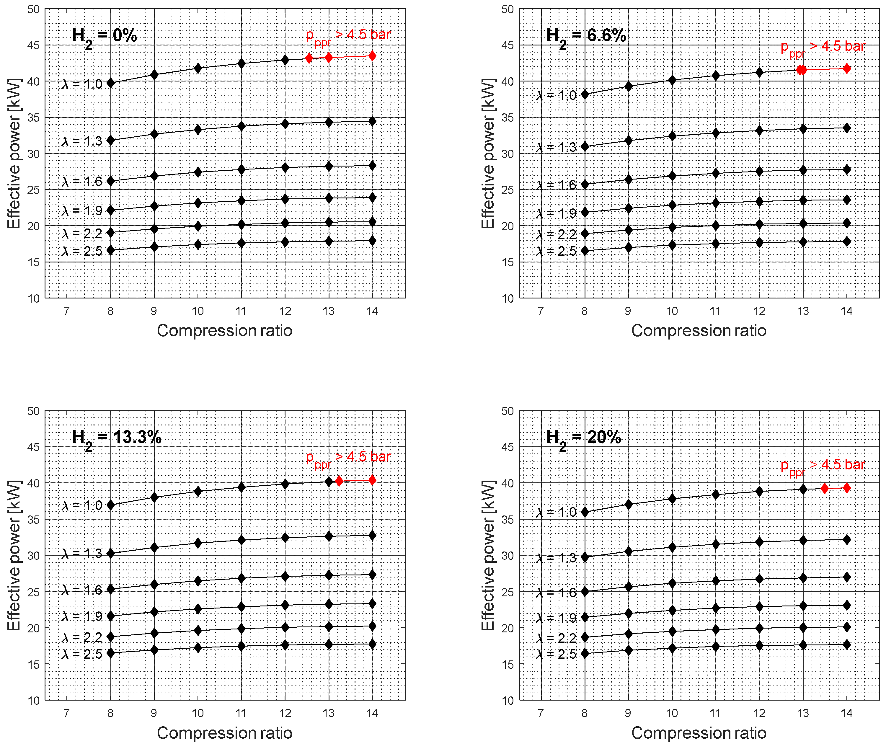
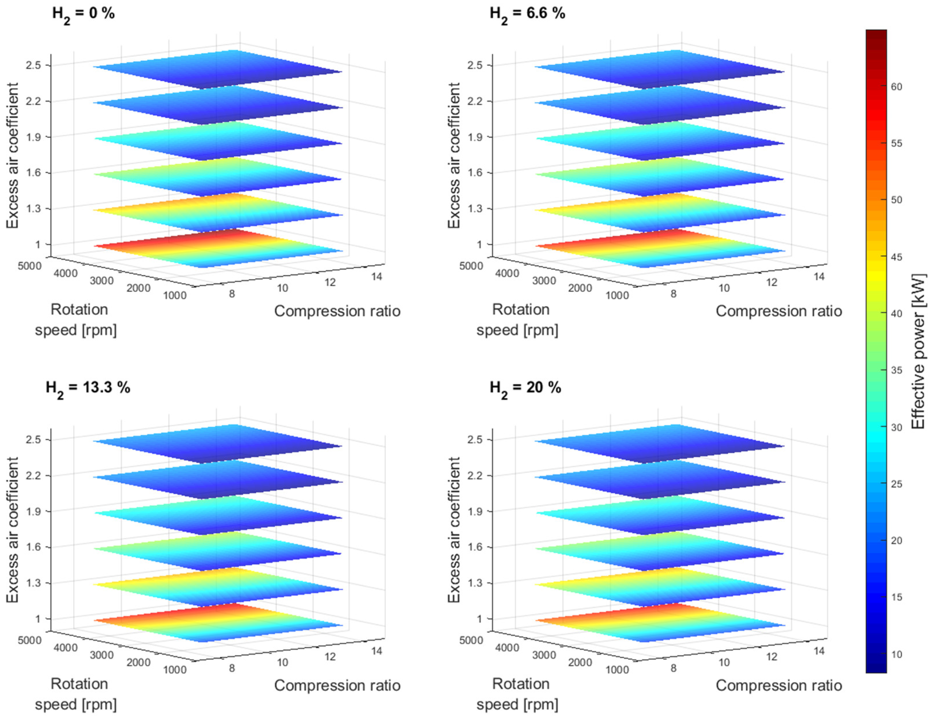
Figure 2 shows the effective power simulation results as a function of compression ratio and excess air coefficient for different gasoline-hydrogen blend levels at a 3000 rpm point of operation. The effective power resulted in the highest values for 0% hydrogen blend level for all considered excess air coefficients and compression ratios. With the addition of hydrogen into the fuel-blend mixture, the effective power dropped gradually by 3.24% on average for an excess air coefficient value of 1 and by 0.41% on average for an excess air coefficient value of 2.5, with each level of hydrogen increase. The overall average drop in effective power with a 20% hydrogen blend level, compared to a 0% hydrogen blend level, resulted in 9.45% and 1.22% for excess air coefficients 1 and 2.5, respectively. A similar trend in a drop of power can also be observed for other crankshaft rotation speeds,
Figure 3.
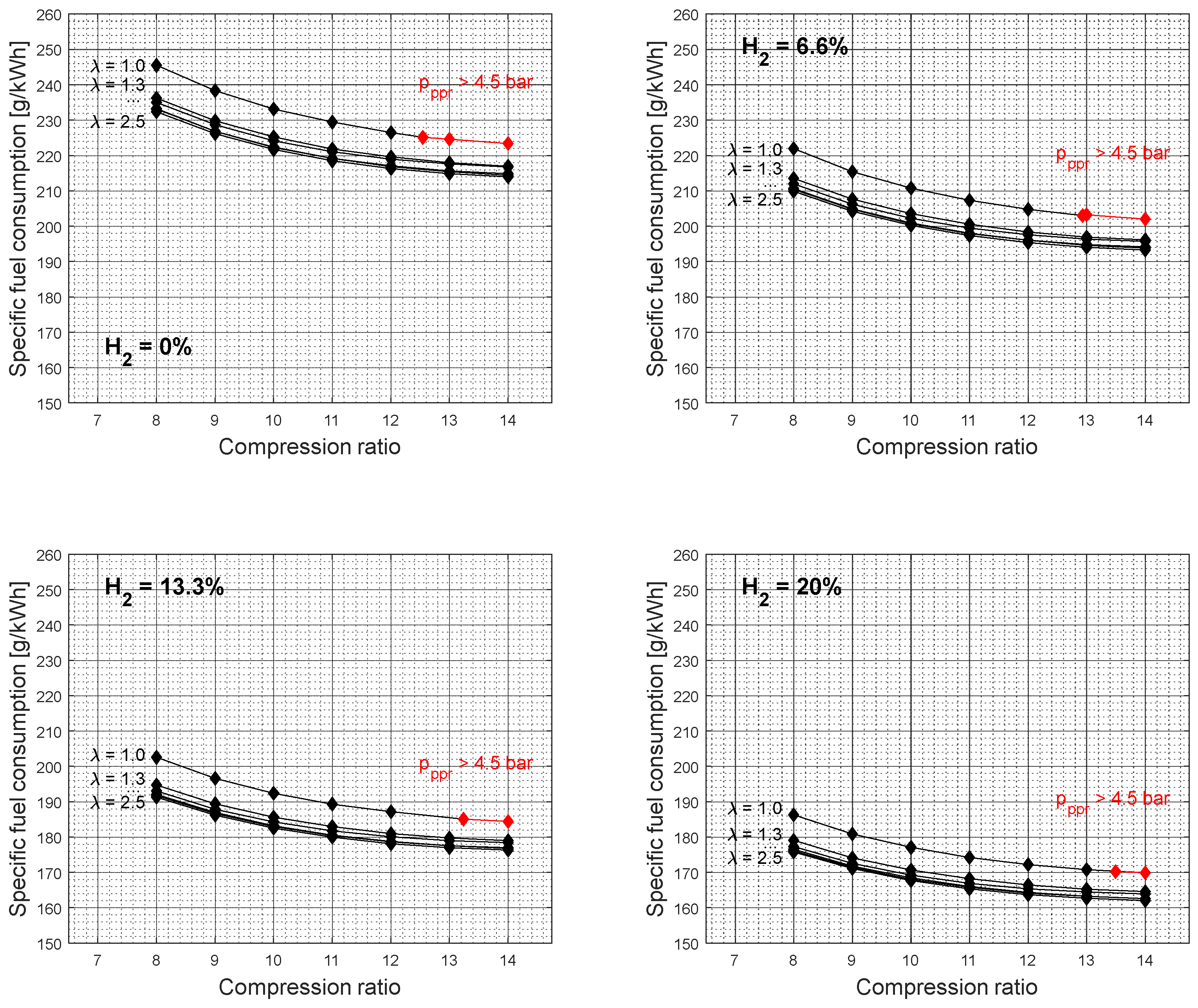
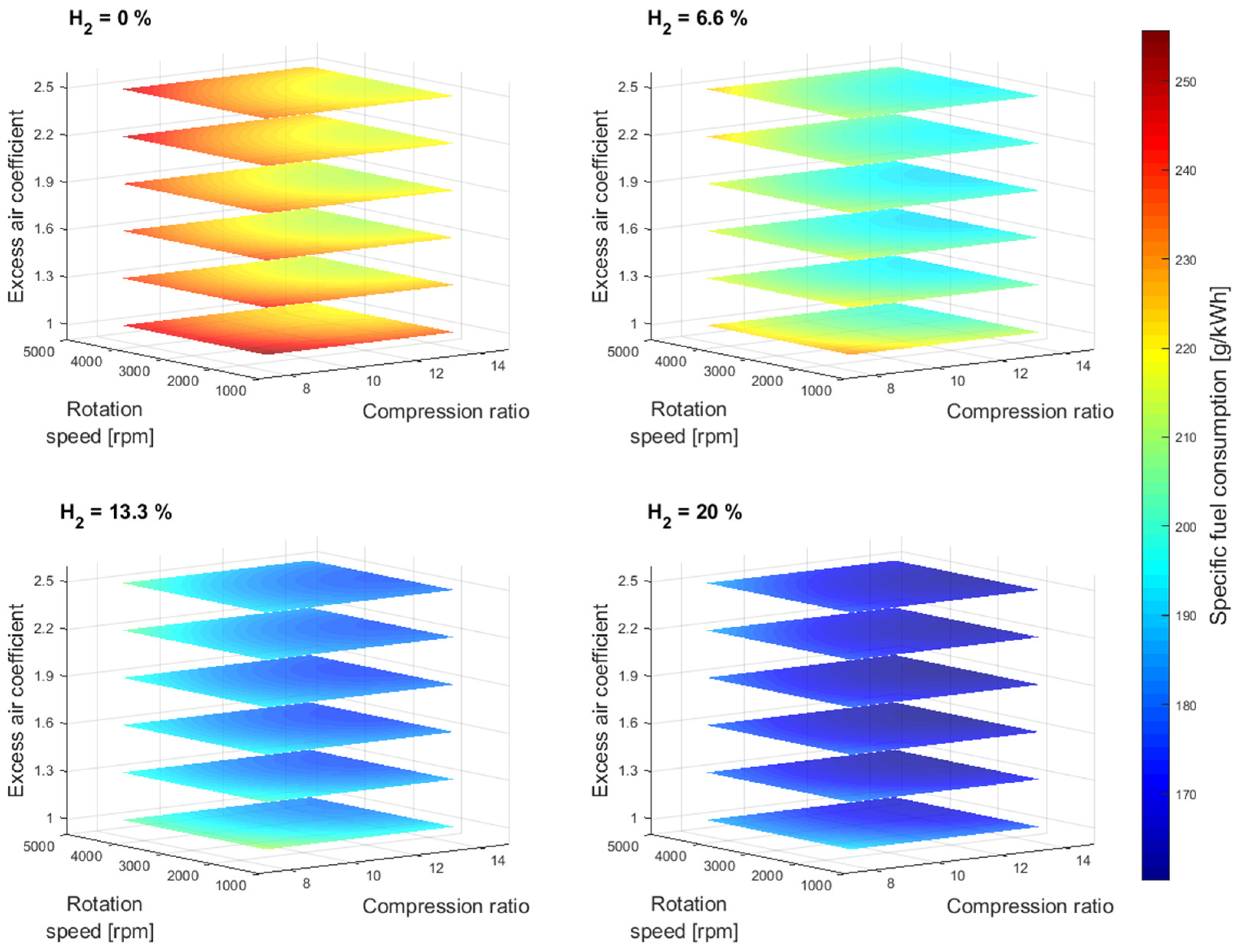
Figure 4 shows the specific fuel consumption simulation results as a function of compression ratio and excess air coefficient for different gasoline-hydrogen blend levels at a 3000 rpm point of operation. The specific fuel consumption resulted in the highest values for 0% hydrogen blend level for all considered excess air coefficients and compression ratios. With the addition of hydrogen into the fuel-blend mixture, the specific fuel consumption dropped gradually by 8.75% on average for all excess air coefficients considered. The average drop in specific fuel consumption values with a 20% hydrogen level, compared to a 0% hydrogen level, resulted in 24.03%. The average specific fuel consumption difference between 1 and 2.5 excess air coefficient resulted in 5% for all hydrogen blend levels considered.
Figure 5 shows the specific fuel consumption simulation results for other crankshaft rotation speeds. As the hydrogen concentration level increases within the gasoline-hydrogen blend, so does the overall air-to-fuel ratio, so accordingly, the air and fuel-blend mixture becomes leaner for the same excess air coefficient values. Therefore, the overall gasoline-hydrogen blend mass on the intake is smaller with each increase in hydrogen level, resulting in lower specific fuel consumption values as well as lower effective power. However, the reduction of specific fuel consumption values was not affected by the drop of corresponding effective power values, as the difference of input energy for different gasoline-hydrogen blends due to the lack of overall blend mass was compensated by the better gasoline-hydrogen blend lower heating value. Furthermore, the leaner fuel-blend mixture also resulted in lower CO
2 emissions with each level of hydrogen. With the addition of hydrogen into the gasoline mixture, the CO
2 emission level dropped gradually by 11.72% on average, while the overall average drop of CO
2 emission level with a 20% hydrogen level, compared to a 0% hydrogen level, resulted in 31.21%.
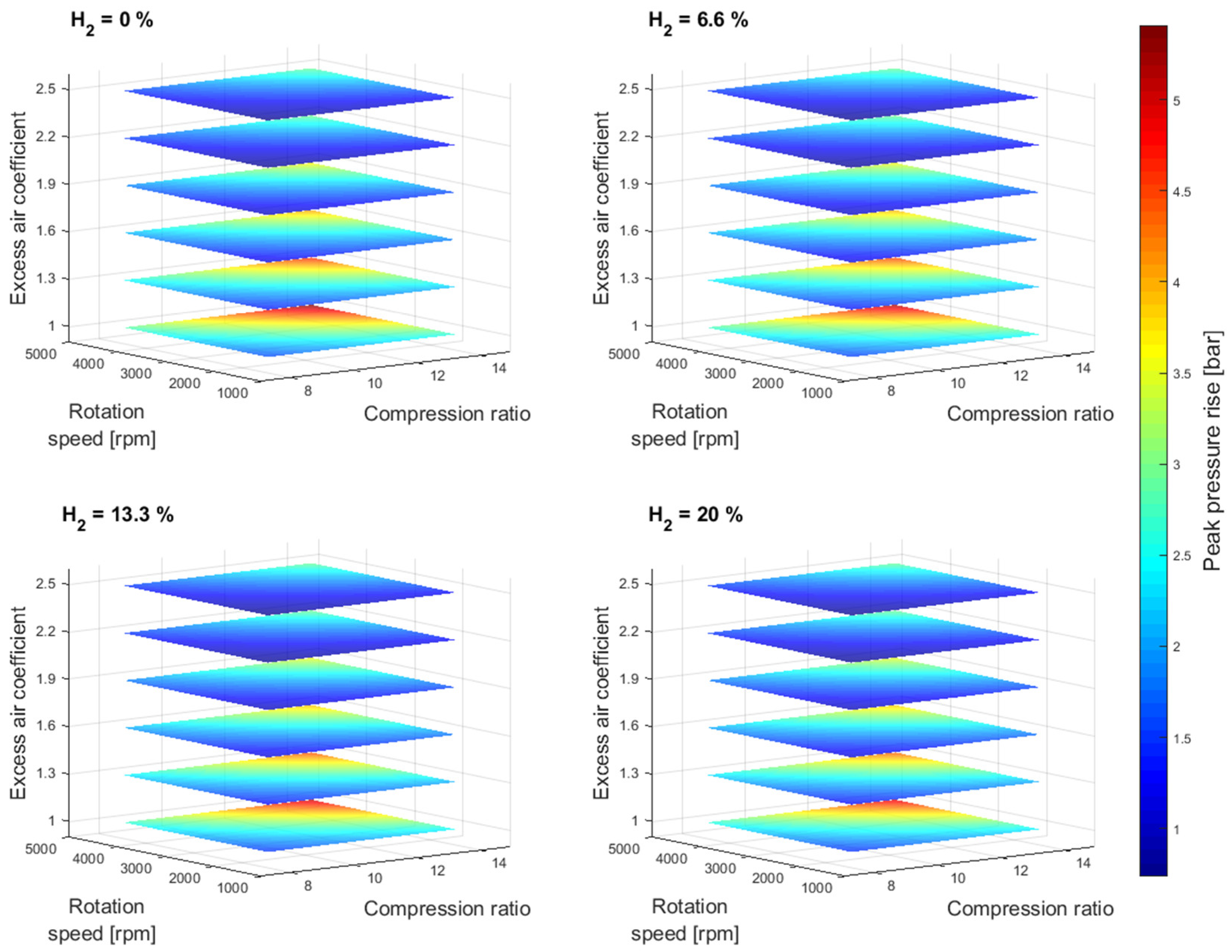
At higher compression ratio values, the effective power resulted in higher values and the specific fuel consumption in lower values. However, the results also show an unfavorable engine operation area at higher compression ratio values for an excess air coefficient of 1,
Figure 2 and
Figure 4. Furthermore, with the addition of hydrogen into the gasoline mixture, the unfavorable area of engine operation as a function of the compression ratio is reduced. A similar trend can also be observed for other rotation speed values,
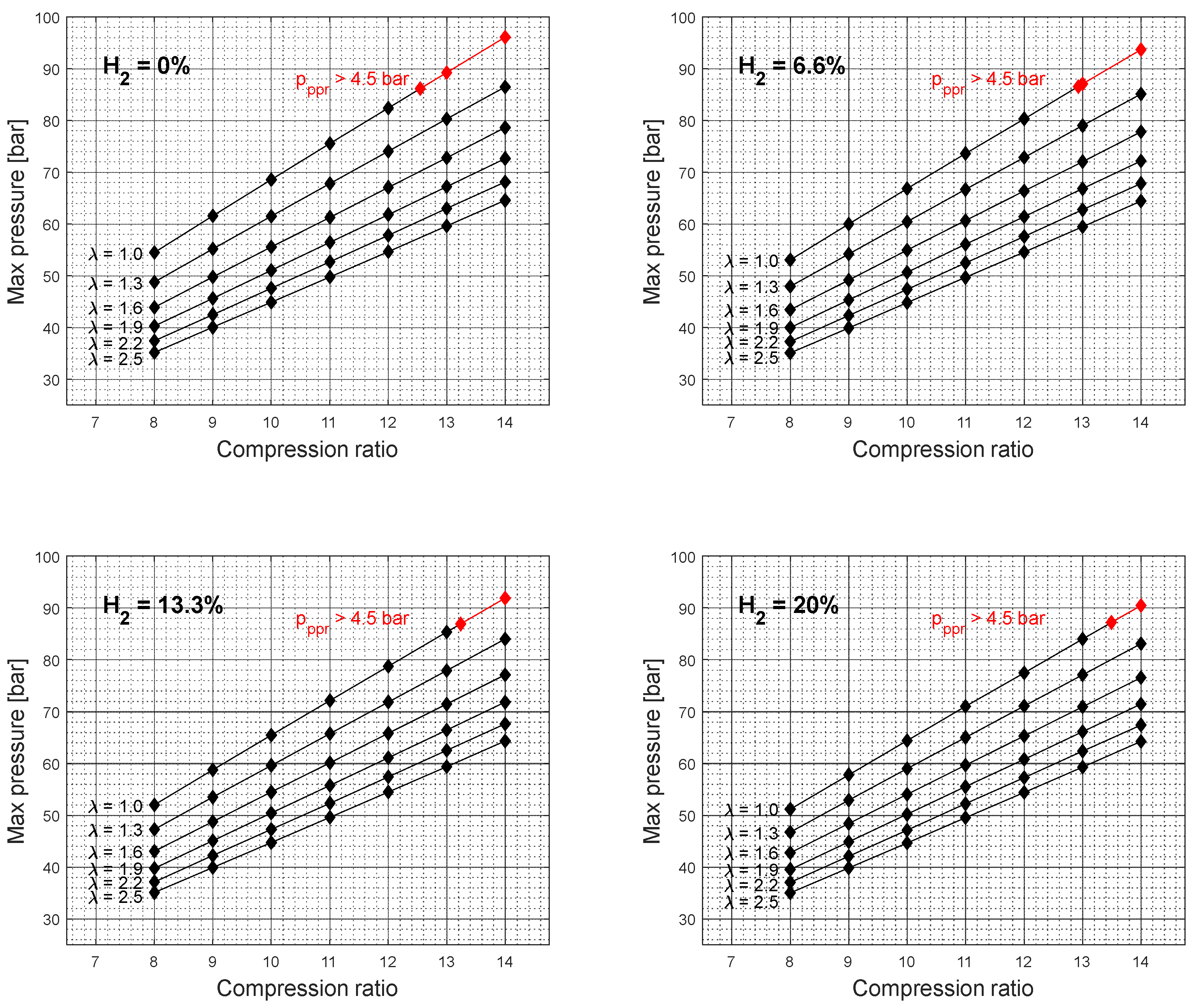
Figure 6. It should also be noted that the elevated peak pressure rise level above 4.5 bar was not recorded for the excess air coefficient values ranging from 1.3 to 2.5. Since the higher excess air coefficient values were achieved by the reduction of the overall gasoline-hydrogen blend mass, the lower overall energy input through the fuel-blend mixture resulted in lower effective power values and lower levels of average pressure at the end of the combustion process,
Figure 7. However, if the higher excess air coefficient values for the constant fuel-blend mass would be achieved via turbocharging, the higher intake pressure, and higher overall energy input would also affect the average temperature and pressure values at the end of the combustion process, which would create conditions for unfavorable engine operation.
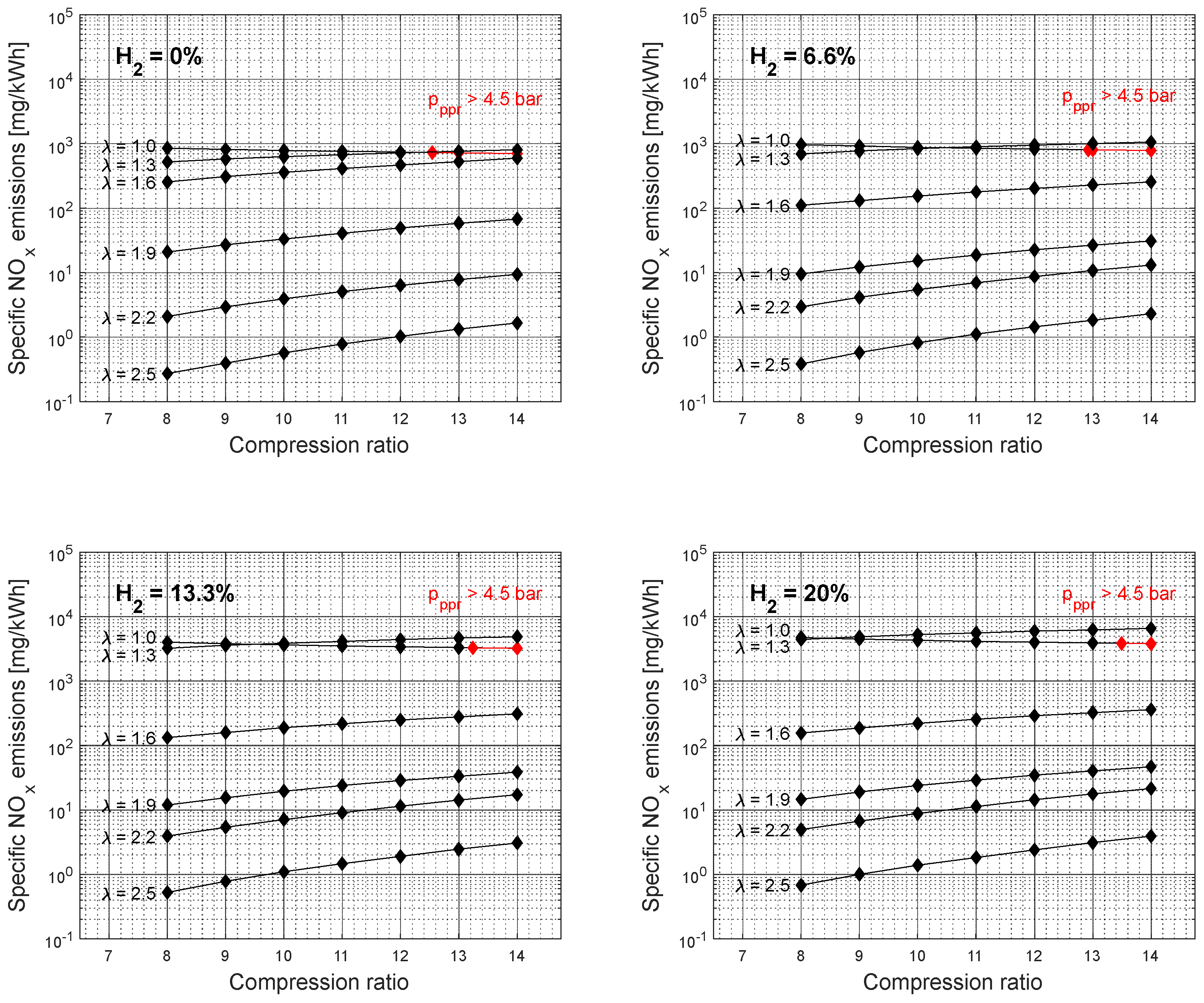
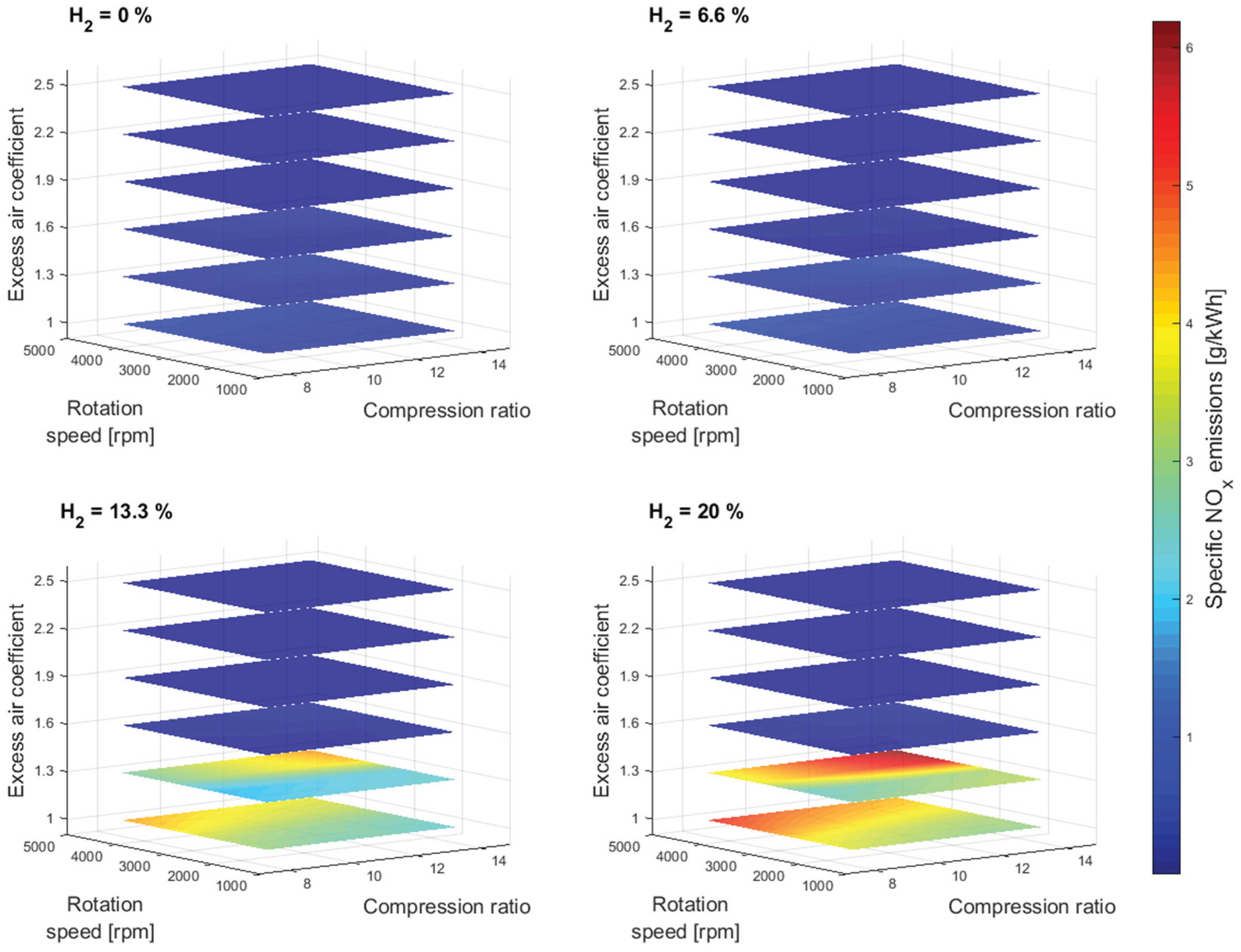
Figure 8 shows the specific NO
x emissions simulation results as a function of compression ratio and excess air coefficient for different gasoline-hydrogen blend levels at a 3000 rpm point of operation. The specific NO
x emissions resulted in higher values with the addition of hydrogen into the fuel-blend mixture. The overall average rise of the specific NO
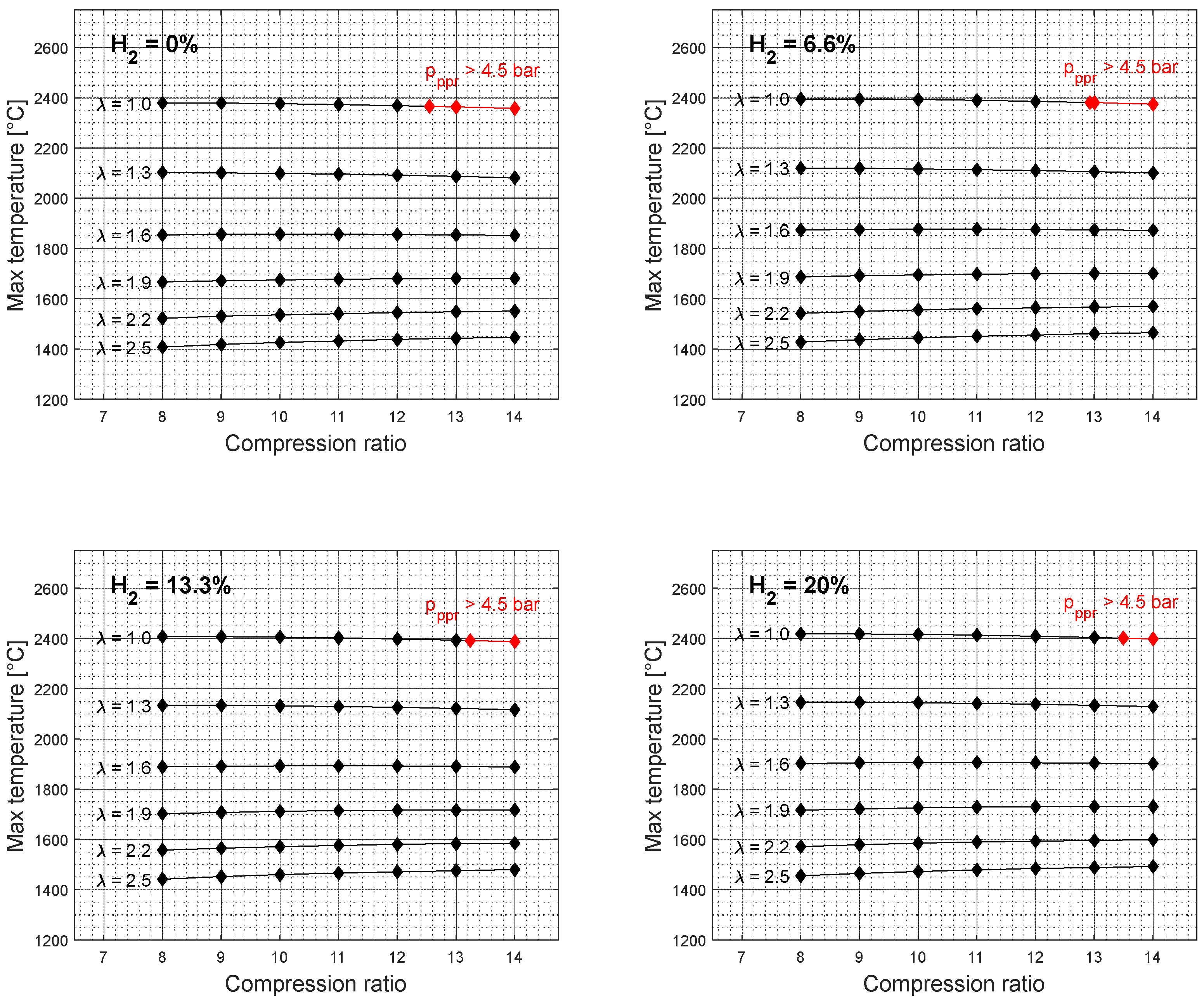
x emissions for 20% hydrogen concentration level, compared to 0%, corresponding to the excess air coefficient 1, resulted in 440%, even though the overall average rise in temperature at the end of the combustion process resulted with only 1.67%, between 0% and 20% hydrogen concentration level, for same considered conditions,
Figure 9. However, the Wiebe Two Zone model separately determines the temperatures of unburned and burned zones. The burned zone, as expected, resulted in considerably higher temperatures compared to the unburned zone due to the thermal energy released during the simulation of the combustion process. Even though the overall fuel-blend mass was reduced with the addition of hydrogen, the lack of fuel was compensated by the better overall fuel-blend calorific value. Therefore, adding hydrogen increased the fuel-blend calorific value, resulting in higher temperatures within the burned zone and creating better conditions for NO
x generation. Furthermore, adding hydrogen increased the potential for NO
x generation at an excess air coefficient of 1.3. With each level of hydrogen increase, specific NO
x emissions corresponding to an excess air coefficient of 1.3 exceeded specific NO
x emissions corresponding to an excess air coefficient of 1 at a lower compression value. This would suggest that the beneficial conditions for NO
x generation are easily created by adding hydrogen to the gasoline and with a small amount of excess oxygen.
Figure 10 shows the specific NO
x emissions simulation results for other crankshaft rotation speeds.
4. Conclusion
This research explored the feasibility of utilizing blends of hydrogen and gasoline within internal combustion engines, evaluating different hydrogen ratios up to 20%. The scope of the study extended across various engine operational points to assess how hydrogen enrichment affects engine performance and pollutant emissions. The findings indicated that adding hydrogen to the fuel blend generally leads to a decrease in the engine’s effective power, with a significant reduction of 9.45% observed for blends containing 20% hydrogen. This reduction is attributed to the resulting leaner air-fuel mixture when hydrogen is added.
On the other side, there was a notable decrease in specific fuel consumption, which fell by an average of 24.03% for the 20% hydrogen mixture. This improvement primarily stems from the greater heating value of the hydrogen-gasoline mixtures. Likewise, a considerable decline in carbon dioxide emissions was recorded, with an average cutback of 31.21% at the maximum level of hydrogen blending. Investigations into compression ratio effects demonstrated that higher ratios could enhance power and diminish fuel consumption. Nonetheless, overly high compression might induce unfavorable combustion conditions, which can be partially mitigated by hydrogen’s introduction.
However, the research also uncovered a significant issue: a dramatic increase in nitrogen oxides (NO
x) emissions, which escalated by an average of 440% with a 20% hydrogen mixture under certain conditions. This rise in NO
x emissions correlates with the elevated temperatures in the combustion zone, another effect of hydrogen’s higher heating value. The introduction of hydrogen into gasoline for use in internal combustion engines affects not only efficiency and emissions but also alters combustion dynamics, leading to leaner combustion. Although lean combustion offers several advantages, such as improved fuel efficiency and lowered CO
2 emissions, it necessitates the implementation of sophisticated exhaust aftertreatment technologies to counteract the increased NO
x emissions, including strategies like exhaust gas recirculation, selective catalytic reduction (SCR) [
32], lean NO
x traps [
32], and NO
x adsorbers.
In summary, integrating hydrogen with gasoline emerges as a viable strategy to boost engine efficiency and lower CO2 emissions. However, this method introduces the challenge of controlling increased NOx emissions, requiring a delicate optimization of engine operational parameters to leverage the advantages while overcoming the negatives. This investigation provides a foundation for subsequent research and development aimed at refining hydrogen utilization in internal combustion engines, underscoring the intricate balance between efficiency improvements and emission management. Future research will cover the control of parameters influencing the combustion process of electronically controlled dual-fuel engines.
