Preprint
Article

Analytical Theory of Fractional Vibrations

Altmetrics

Downloads

103

Views

46

Comments

0

Ming Li  *

This version is not peer-reviewed

Submitted:

29 February 2024

Posted:

01 March 2024

You are already at the latest version

Alerts
Abstract
This paper revisits the analytical theory of fractional vibrations with the highlights in five aspects. First, we address the cases of structures with frequency dependent mass or damping or stiffness in Sections 2-4. Second, we introduce the theory based on the general second-order vibration motion equation with frequency dependent elements (mass, damping, stiffness) in Sections 5-7. Third, we present the analytical theory of seven specific classes of second-order vibration systems with frequency dependent mass or damping or stiffness in Sections 8 and 9. Fourth, we bring forward the analytical theory of seven classes of fractional vibration systems in Sections 10-12. Finally, as an application, we give the closed form expression of the forced response to multi-fractional Euler-Bernoulli beam in Section 13. The explanation of the nonlinearity of fractional vibrations is given in Section 14.
Keywords: 
Subject: Engineering  -   Mechanical Engineering

1. Introduction

Conventionally, vibration elements, say, mass m, damping c, and stiffness k, are commonly assumed to be constants. However, in vibration engineering, people pay attention to the phenomena of frequency dependent elements (mass or damping or stiffness), see e.g., Harris [1], Korotkin [2], Palley et al. [3], Kristiansen and Egeland [4], Zou et al. [5], Wu and Hsie [6], Qiao et al. [7], Jaberzadeh et al. [8], Xu et al. [9], Ghaemmaghami and Kwon [10], Hamdaoui et al. [11]. Since the analytical theory of fractional vibrations established by Li [12,13,14] adopts frequency dependent elements in the equivalent sense, we feel the usefulness of showing several realistic cases of frequency dependent mass, damping, and stiffness respectively in Section 2, Section 3 and Section 4, so as to purposely write a general form of a vibration system with frequency dependent mass, damping, and stiffness and discuss its vibration theory in Section 5, Section 6, Section 7, Section 8 and Section 9. The intention of writing Section 5, Section 6, Section 7, Section 8 and Section 9 is in two aspects. One is for the pavement of seven classes of fractional vibrators addressed in Section 10, Section 11, Section 12 and Section 13. The other is to facilitate smoothing away possible hesitations why m and or c and or k may be frequency dependent. As an application, we discuss the closed form expression of the forced response to the multi-fractional Euler-Bernoulli beam in Section 13. The nonlinearity of fractional vibrations is discussed in Section 14, which is followed by conclusions.

2. Cases of Frequency Dependent Mass

2.1. Frequency Dependent Mass in Auxiliary Mass Damper System

Consider a simple auxiliary mass damper indicated in Figure 1 (Harris [1]). The system consists of a mass ma, spring ka, and viscous damper ca.
The motion equation of the auxiliary mass damper system is given by
k a x r ( t ) c a d x r ( t ) d t = m a d 2 [ x 0 ( t ) + x r ( t ) ] d t 2 .
Let Xr and X0 be the phasors of xr(t) and x0(t), respectively. The phasor equation of the above is in the form
( k a i ω c a ) X r = m a ω 2 ( X r + X 0 ) .
Therefore,
X r = m a ω 2 m a ω 2 + k a + i ω c a .
Denote by F the phasor of the force exerting on the foundation. Then,
F = m a ω 2 ( k a + i ω c a ) m a ω 2 + k a + i ω c a X 0 .
As the force acted by an equivalent mass meq is rigidly attached to the foundation, we have
F = m eq ω 2 X 0 ,
where
m eq = k a + i ω c a m a ω 2 + k a + i ω c a m a .
Rewriting the above yields
m eq = ( k a + i ω c a ) ( k a m a ω 2 i ω c a ) ( k a m a ω 2 ) 2 + ( ω c a ) 2 m a = k a ( k a m a ω 2 ) + ( ω c a ) 2 i m a c a ω 3 ( k a m a ω 2 ) 2 + ( ω c a ) 2 m a .
In the polar system,
m eq = | m eq | Arg m eq ,
where
| m eq | = [ k a ( k a m a ω 2 ) + ( ω c a ) 2 ] 2 + ( m a c a ω 3 ) 2 ( k a m a ω 2 ) 2 + ( ω c a ) 2 m a ,
and
Arg m eq = tan 1 i m a c a ω 3 k a ( k a m a ω 2 ) + ( ω c a ) 2 .
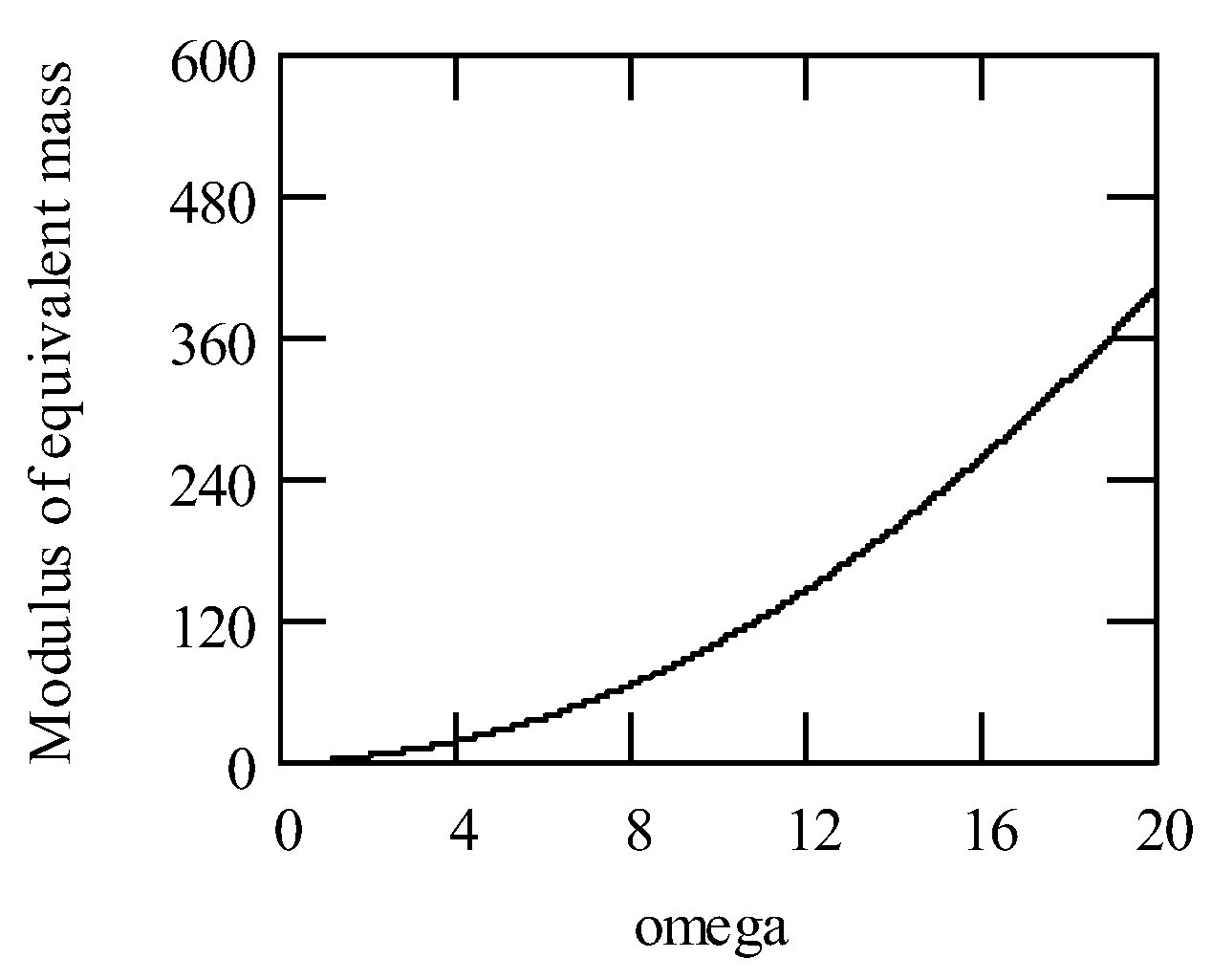
The above exhibits that both the modulus and argument of meq are the functions of ω. When ω = 0, meq reduces to the primary mass ma. In general, 0 ≤ |meq| < ∞. When ca = 0, meq is real. Figure 2 illustrates a curve of |meq|.

2.2. Added Mass

The frequency dependence of added mass is well known in the field of ship mechanics (Korotkin [2]). In general, a ship motion is with six degrees of freedom (Palley et al. [3]). We adopt the following symbols for discussions.
  • qn (n = 1, …, 6): generalized coordinates.
  • fn: generalized forces.
  • mjn: dry mass of the ship in direction j.
  • cjn: dry damping of the ship in direction j.
  • kjn: dry stiffness of the ship in direction j.
  • madd, jn: added mass of the ship in direction j.
  • hjn(t): impulse response function in direction j to an impulse in velocity in direction n.
When qn(t) = qn cos(ωt), according to Kristiansen and Egeland [4], one has
n = 1 6 [ m j n + m add , j n ( ω ) ] q n + n = 1 6 c eq , j n ( ω ) q n + n = 1 6 k j n q n = f j ( t ) ,
where fj(t) is a sinusoidal force at ω,
m add , j n ( ω ) = m j n 1 ω 0 h j n ( t ) sin ω t d t
and
c eq , j n ( ω ) = c j n + 0 h j n ( t ) cos ω t d t .
Considering the equivalent mass meq, we have
meq = mjn + madd, jn(ω).
Therefore, the equivalent mass meq of a ship in general is frequency dependent. Consequently, meq = meq(ω).
There are other types of expressions with respect to frequency dependent mass, see e.g., Zou et al. [5], Wu and Hsieh [6], Qiao et al. [7], Jaberzadeh et al. [8], Xu et al. [9], Ghaemmaghami, and Kwon [10], Hamdaoui et al. [11], Li [12,13,14], Banerjee [15], White et al. [16], Dumont and Oliveira [17], Zhang et al. [18], Sun et al. [19].

3. Cases of Frequency Dependent Damping

3.1. Rigidly Connected Coulomb Damper

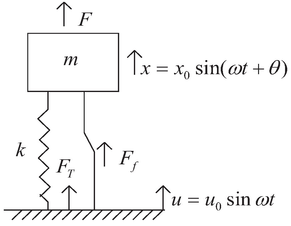
Have a look at Figure 3 that indicates a rigidly connected Coulomb damper.
The motion equation is given by
m x + k ( x u ) ± F f = F 0 + sin ω t .
Since there is discontinuity in the damping force that occurs as the sign of the velocity changes at each half cycle, a step-by-step solution of the above is required (Harris [1], Den Hartog [20]). Let δ = xu. Using the equivalence of energy dissipation for equating the energy dissipation per cycle for viscous-damped and Coulomb damped systems produces (Harris [1], Jacobsen [21])
π c eq ω δ 0 2 = 4 F f δ 0 .
In the above, the left side refers to the viscous-damped system and the right side to the Coulomb-damped system. The symbol δ0 is the amplitude of relative displacement across the damper.
From the above, one has the equivalent viscous damping coefficient for a Coulomb-damped system that has equivalent energy dissipation in the form
c eq = 4 F f π ω δ 0 .
One thing worth noting is that ceq is frequency dependent. Hence,
ceq = ceq(ω).

3.2. Rayleigh Damping

The Rayleigh damping introduced by Rayleigh [22] is widely adopted in the field, see e.g., Harris [1], Palley et al. [3], Li [12,13,14], Jin and Xia [23], Trombetti and Silvestri [24,25], Mohammad et al. [26], Kim and Wiebe [27]. Rayleigh assumed his damping in the form
cRaylegh = am + bk,
where a is proportional to ω while b is inversely proportional to ω. Thus, we may write
cRaylegh = cRaylegh(ω).
The above exhibits that the frequency dependence is a radical property of the damping Rayleigh assumed.

3.3. Remarks

Other types of frequency dependent dampers, refer to Kuo et al. [28], Stollwitzer et al. [29], Jith and Sarkar [30], Zhou et al. [31], Zarraga et al. [32], Xie et al. [33,34], Hu et al. [35], Rouleau et al. [36], Hamdaoui et al. [37], Deng et al. [38], Dai et al. [39], Adessina et al. [40], Chang et al. [41], Lin et al. [42], Dai et al. [43], Catania and Sorrentino [44,45], Zhang and Turner [46], Yoshida et al. [47], Assimaki and Kausel [48], Pan et al. [49], Ghosh and Viswanath [50], Mcdaniel et al. [51], Zhang et al. [52], Wang et al. [53], Lundén and Dahlberg [54], Figueroa et al. [55], Lázaro [56], and Crandall [57], simply citing a few.

4. Cases of Frequency Dependent Stiffness

4.1. Frequency Dependent Stiffness in a Shaft Driven by a Periodic Force

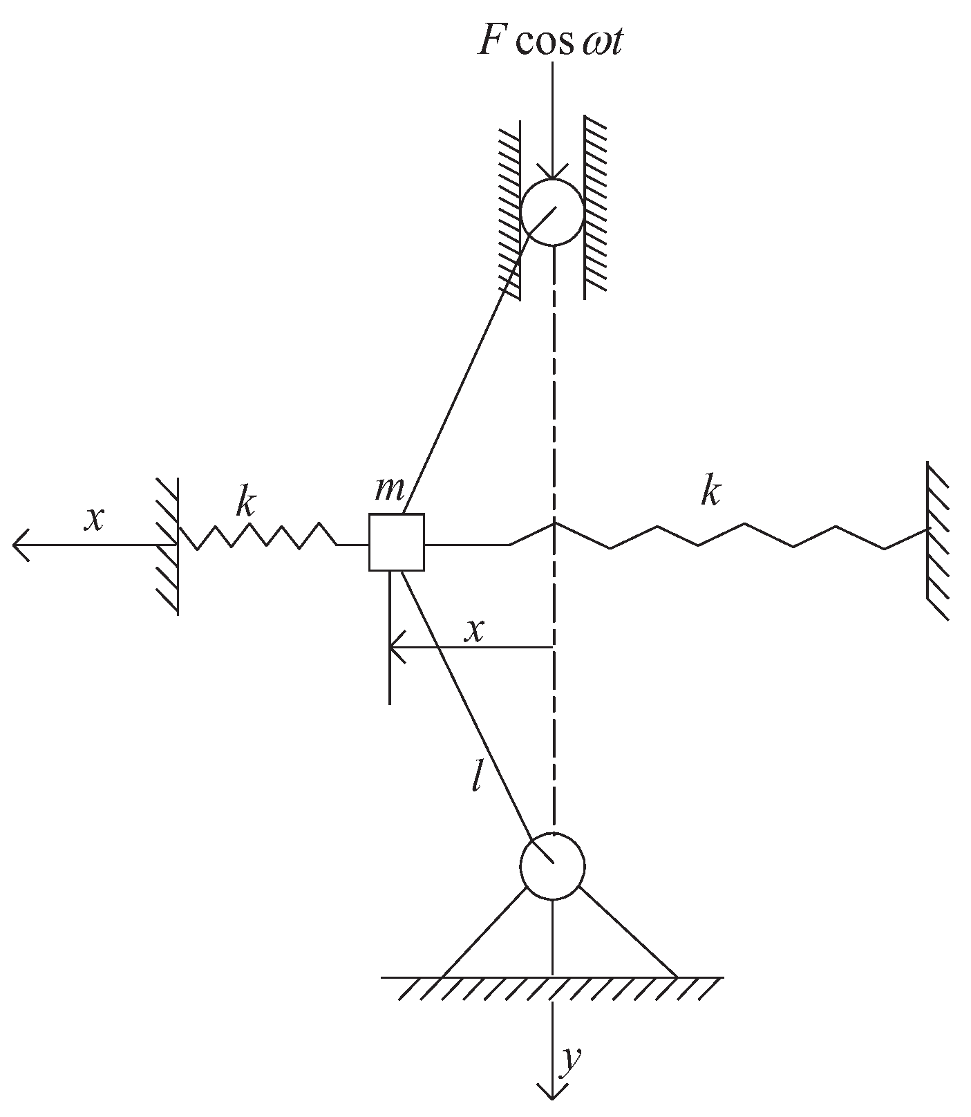
Consider a shaft driven by a periodic force as shown in Figure 4. The mass m is supported by two springs with the primary stiffness k. Under the excitation of a force in axis direction, there is a force produced by displacement in the form x l F cos ω t .
Thus, the motion equation is given by
m x + k x x l F cos ω t = 0 .
Denote by keq the equivalent stiffness of the system. Then,
m x + k eq x = 0 ,
where
k eq = k F cos ω t l .
The above designates that the equivalent stiffness keq is frequency dependent. Hence, keq = keq(ω).

4.2. Frequency Dependent Stiffness in Simple Pendulum

Let l be the length of a simple pendulum. Denote by m the mass of the simple pendulum. Suppose that the fulcrum position of the pendulum moves periodically as A0cosxl, see Figure 5.
The motion equation of the simple pendulum is given by
m l θ + m ( g ω 2 A 0 cos ω t ) sin θ = 0 .
When θ is small such that sinθθ, we have
m l θ + m ( g ω 2 A 0 cos ω t ) θ = 0 .
Replacing θ by x yields
m x + m l ( g ω 2 A 0 cos ω t ) x = 0 .
Let keq be the equivalent stiffness. Then,
k eq = m l ( g ω 2 A 0 cos ω t ) .
Therefore, the motion equation is expressed by
m x + k eq x = 0 .
The above exhibits that the stiffness keq is frequency dependent.
The topic of frequency dependent stiffness attracts the interests of researchers. The other references regarding frequency dependent stiffness refer to Li [12,13,14], Banerjee [15], White et al. [16], Dumont and de Oliveira [17], Zhang et al. [18], Sun et al. [19], Yoshida et al. [47], Wu et al. [58], Blom and Kari [59], Gao et al. [60], Song et al. [61], Liu et al. [62], Zhang et al. [63], Banerjee et al. [64,65], Lu et al. [66], Sung et al. [67], Mezghani et al. [68], Liu et al. [69], Kong et al. [70], Ege et al. [71], Mukhopadhyay et al. [72], Sainz-AjaIsidro et al. [73], Bozyigit [74], Varghese et al. [75], Failla et al. [76], Fan et al. [77], Roozen et al. [78], Mochida and Ilanko [79], just citing a few.

5. General Vibration System with Frequency Dependent Elements

5.1. Motion Equation of General Vibration System

Based on the previous discussions, we write the motion equation with frequency dependent elements by
m eq ( ω ) x + c eq ( ω ) x + k eq ( ω ) x = f ( t ) ,
where f(t) is an excitation force.
Let X(ω) and F(ω) be the Fourier transform of x(t) and f(t), respectively. Then, the motion equation in the frequency domain is expressed by
[ ω 2 m eq ( ω ) + i ω c eq ( ω ) + k eq ( ω ) ] X ( ω ) = F ( ω ) .

5.2. Vibration Parameters of General Vibration System

Denote by ωeqn the equivalent natural angular frequency with damping free. It is given by
ω eqn = k eq ( ω ) m eq ( ω ) .
Since either meq or keq is a function of ω, ωeqn is a function of ω. Thus,
ω eqn = ω eqn ( ω ) .
Let ζeq(ω) be the equivalent damping ratio in the form
ς eq ( ω ) = 1 2 c eq m eq k eq .
Then, we rewrite (5.1) by
x + 2 ς eq ( ω ) ω eqn ( ω ) x + ω eqn 2 ( ω ) x = f ( t ) m eq ( ω ) .
Denote by ωeqd(ω) the equivalent damped natural angular frequency. Since |ζeq(ω)| > 1 does not make sense in vibrations (Harris [1], Palley et al. [2], Li [13], Nakagawa and Ringo [80]), we restrict ζeq by |ζeq(ω)| ≤ 1. Thus,
ω eqd ( ω ) = ω eqn ( ω ) 1 ς eq 2 ( ω ) .
The equivalent frequency ratio is given by
γ eq = ω ω eqn ( ω ) .

5.3. Free Response of General Vibration System with Frequency Dependent Elements

When considering the free response to a general vibration system with frequency dependent elements, we have
{ m eq ( ω ) x ( t ) + c eq ( ω ) x ( t ) + k eq ( ω ) x ( t ) = 0 , x ( 0 ) = x 0 , x ( 0 ) = v 0 .
The above equation can be rewritten by
{ x + 2 ς eq ( ω ) ω eqn ( ω ) x + ω eqn 2 ( ω ) x = 0 , x ( 0 ) = x 0 , x ( 0 ) = v 0 .
Then, the free response is
x ( t ) = e ς eq ω eqn t ( x 0 cos ω eqd t + v 0 + ς eq ω eqn x 0 ω eqd sin ω eqd t ) ,   t 0 .

5.4. Impulse Response of General Vibration System with Frequency Dependent Elements

When investigating the impulse response to a general vibration system with frequency dependent elements, we use the following equation
{ h ( t ) + 2 ς eq ( ω ) ω eqn ( ω ) h ( t ) + ω eqn 2 ( ω ) h ( t ) = δ ( t ) m eq ( ω ) , h ( 0 ) = 0 , h ( 0 ) = 0 .
Thus,
h ( t ) = e ς eq ω eqn t 1 m eq ω eqd sin ω eqd t , t 0 .

5.5. Step Response of General Vibration System with Frequency Dependent Elements

Denote by g(t) the unit step response (step response for short) to a general vibration system with frequency dependent elements. Consider the following equation
{ g ( t ) + 2 ς eq ( ω ) ω eqn ( ω ) g ( t ) + ω eqn 2 ( ω ) g ( t ) = u ( t ) m eq ( ω ) , g ( 0 ) = 0 , g ( 0 ) = 0 .
Then,
g ( t ) = 1 k eq ( ω ) [ 1 e ς eq ω eqn t 1 ς eq 2 cos ( ω eqd t ϕ ) ] , t 0 ,
where
ϕ = tan 1 ς eq 1 ς eq 2 .

6. Frequency Transfer Function of General Vibration System with Frequency Dependent Elements

Let H(ω) be the Fourier transform of h(t). From (5.12), we have
[ ω eqn 2 ( ω ) ω 2 + i 2 ς eq ( ω ) ω eqn ( ω ) ω ] H ( ω ) = 1 m eq ( ω ) .
Therefore,
H ( ω ) = 1 m eq ( ω ) [ ω eqn 2 ( ω ) ω 2 + i 2 ς eq ( ω ) ω eqn ( ω ) ω ] = 1 k eq ( ω ) [ 1 γ eq 2 + i 2 ς eq ( ω ) γ eq ] .
The amplitude |H(ω)| is given by
| H ( ω ) | = 1 / k eq ( 1 γ eq 2 ) 2 + ( 2 ς eq γ eq ) 2 .
The phase is expressed by
φ ( ω ) = tan 1 2 ς eq ( ω ) γ eq 1 γ eq 2 .
When computing ϕ(ω) using digital computers,
φ ( ω ) = cos 1 1 γ eq 2 ( 1 γ eq 2 ) 2 + ( 2 ς eq γ eq ) 2 .

7. Logarithmic Decrement and Q Factor of General Vibration System with Frequency Dependent Elements

Let ti and ti + 1 be two time points of the free response x(t), where x(ti) and x(ti + 1) are successive peak values at ti and ti + 1. Let Δeq be the logarithmic decrement of x(t). Then,
Δ eq = Δ eq ( ω ) = ln x ( t i ) x ( t i + 1 ) = 2 π ς eq ( ω ) 1 ς eq 2 ( ω ) .
Let Qeq be the Q factor of a general vibration system with frequency dependent elements. Then,
Q eq = Q eq ( ω ) = 1 2 ς eq ( ω ) .

8. Li's Vibration System with Frequency Dependent Elements

8.1. Motion Equation of Li's Vibration System

Recently, Li introduced a class of vibration systems with frequency dependent elements. Its motion equation is in the form
( m ω α 2 cos α π 2 + c ω β 2 cos β π 2 ) d 2 x 6 ( t ) d t 2 + ( m ω α 1 sin α π 2 + c ω β 1 sin β π 2 + k ω λ 1 sin λ π 2 ) d x 6 ( t ) d t + k ω λ cos λ π 2 x 6 ( t ) = f ( t ) , 1 < α < 3 ,   0 < β < 2 ,   0 λ < 1 ,
where f(t) is driven force and x6(t) is the response. For facilitating discussions, we call the above Li's vibration system with frequency dependent elements or Li's vibration system in short.

8.2. Vibration Parameters of Li's Vibration System

When writing (8.1) by
m eq 6 d 2 x 6 ( t ) d t 2 + c eq 6 d x 6 ( t ) d t + k eq 6 x 6 ( t ) = f ( t ) , 1 < α < 3 ,   0 < β < 2 ,   0 λ < 1 ,
we have the equivalent mass of (8.1) in the form
m eq 6 = m eq 6 ( ω ) = ( m ω α 2 cos α π 2 + c ω β 2 cos β π 2 ) ,
the equivalent damping expressed by
c eq 6 = c eq 6 ( ω ) = c ω β 1 sin β π 2 + k ω λ 1 sin λ π 2 ,
and the equivalent stiffness given by
k eq 6 = k eq 6 ( ω ) = k ω λ cos λ π 2 .
Let ζeq6 be the equivalent damping ratio for the system (8.1). Define it by
ς eq 6 = c eq 6 2 m eq 6 k eq 6 .
Then,
ς eq 6 = ς eq 6 ( ω ) = m ω α 1 sin α π 2 + c ω β 1 sin β π 2 + k ω λ 1 sin λ π 2 2 ( m ω α 2 cos α π 2 + c ω β 2 cos β π 2 ) k ω λ cos λ π 2 .
Denote by ωeqn6 the equivalent natural angular frequency with damping free with respect to the system (8.1). Define it by
ω eqn 6 = k eq 6 ( ω ) m eq 6 ( ω ) .
Then,
ω eqn 6 = k ω λ cos λ π 2 ( m ω α 2 cos α π 2 + c ω β 2 cos β π 2 ) .
Let ωeqd6 be the equivalent damped natural angular frequency for the system (8.1). In vibrations, small damping |ζeq6| ≤ 1 is assumed in what follows. Define ωeqd6 by
ω eqd 6 = ω eqn 6 1 ς eq 6 2 , | ς eq 6 | 1 .
Then,
ω eqd 6 = k ω λ cos λ π 2 ( m ω α 2 cos α π 2 + c ω β 2 cos β π 2 ) 1 ( m ω α 1 sin α π 2 + c ω β 1 s i n β π 2 + k ω λ 1 s i n λ π 2 2 ( m ω α 2 cos α π 2 + c ω β 2 cos β π 2 ) k ω λ cos λ π 2 ) 2 .
Denote the equivalent frequency ratio for the system (8.1) by γeq6 and define it by
γ eq 6 = ω ω eqn 6 .
Then,
γ eq 6 = γ ( ω α 2 cos α π 2 + 2 ς ω n ω β 2 cos β π 2 ) ω λ cos λ π 2 ,
where γ = ω ω n and ω n = k m .

8.3. Free Response of Li's Vibration System

Consider
{ m eq 6 d 2 x 6 ( t ) d t 2 + c eq 6 d x 6 ( t ) d t + k eq 6 x 6 ( t ) = 0 , x 6 ( 0 ) = x 60 , x 6 ( 0 ) = v 60 .
Then, the free response x6(t) is expressed by
x 6 ( t ) = e ς eq 6 ω eqn 6 t ( x 60 cos ω eqd 6 t + v 60 + ς eq 6 ω eqn 6 x 60 ω eqd 6 sin ω eqd 6 t ) ,   t 0 .

8.4. Impulse Response of Li's Vibration System

Let h6(t) be the impulse response of the system (8.1). Then,
h 6 ( t ) = e ς eq 6 ω eqn 6 t 1 m eq 6 ω eqd 6 sin ω eqd 6 t , t 0 .

8.5. Step Response of Li's Vibration System

Denote by g6(t) the unit step response of the system (8.1). Then,
g 6 ( t ) = 1 k eq 6 [ 1 e ς eq 6 ω eqn 6 t 1 ς eq 6 2 cos ( ω eqd 6 t ϕ 6 ) ] , t 0 ,
where
ϕ 6 = tan 1 ς eq 6 1 ζ eq 6 2 .

8.6. Frequency Transfer Function of Li's Vibration System

Let H6(ω) be the frequency transfer function of the system (8.1). Then,
H 6 ( ω ) = 1 k eq 6 ( 1 γ eq 6 2 + i 2 ς eq 6 γ eq 6 ) = 1 k [ ω λ cos λ π 2 + γ 2 ( ω α 2 cos α π 2 + 2 ς ω n ω β 2 cos β π 2 ) + i γ ( ω α 1 sin α π 2 + 2 ζ ω n ω β 1 sin β π 2 + ω n 2 ω λ 1 sin λ π 2 ) ] .

8.7. Logarithmic Decrement and Q Factor of Li's Vibration System

Let ti and ti + 1 be two time points of the fractional free response x6(t), where x6(ti) and x6(ti + 1) are its successive peak values at ti and ti + 1. Let Δeq6 be the equivalent logarithmic decrement of x6(t). Then,
Δ eq 6 = ln x 6 ( t i ) x 6 ( t i + 1 ) = π m ω α 1 sin α π 2 + c ω β 1 sin β π 2 + k ω λ 1 sin λ π 2 ( m ω α 2 cos α π 2 + c ω β 2 cos β π 2 ) k ω λ cos λ π 2 1 ( m ω α 1 sin α π 2 + c ω β 1 s i n β π 2 + k ω λ 1 s i n λ π 2 ) 2 4 [ ( m ω α 2 cos α π 2 + c ω β 2 cos β π 2 ) k ω λ cos λ π 2 ] .
Denote by Qeq6 the equivalent Q factor of the system (8.1). Then,
Q eq 6 = ( m ω α 2 cos α π 2 + c ω β 2 cos β π 2 ) k ω λ cos λ π 2 m ω α 1 sin α π 2 + c ω β 1 sin β π 2 + k ω λ 1 sin λ π 2 .

8.8. Equivalent Fractional System of Li's Vibration System

Theorem 1.
An equivalent fractional system of Li's vibration system is expressed by
m d α x 6 ( t ) d t α + c d β x 6 ( t ) d t β + k d λ x 6 ( t ) d t λ = f ( t ) .
roof. 
Let F be the operator of Fourier transform. Let
A 6 ( t ) = ( m ω α 2 cos α π 2 + c ω β 2 cos β π 2 ) d 2 x 6 ( t ) d t 2 + ( m ω α 1 sin α π 2 + c ω β 1 sin β π 2 + k ω λ 1 sin λ π 2 ) d x 6 ( t ) d t + k ω λ cos λ π 2 x 6 ( t ) .
Let
B 6 ( t ) = m d α x 6 ( t ) d t α + c d β x 6 ( t ) d t β + k d λ x 6 ( t ) d t λ .
Because F[A6(t)] = F[B6(t)], we have
A6(t) = B6(t)
in the sense of F[A6(t) − B6(t)] = 0. The proof is finished.

9. Seven Classes of Li's Vibration Systems with Frequency Dependent Elements and Their Fractional Equivalences

The system (8.1) contains other six classes of vibration systems with frequency dependent elements. Meanwhile, the system (8.22) includes six other classes of fractional vibration systems. We address them in this subsection.

9.1. Li's Vibration System of Class I and its Fractional Equivalence

When c = 0 and λ = 0 in (8.1), we have the motion equation in the form
m ω α 2 cos α π 2 d 2 x 1 ( t ) d t 2 + m ω α 1 sin α π 2 d x 1 ( t ) d t + k x 1 ( t ) A 1 ( t ) , 1 < α < 3.
The above is called the class I Li's vibration system with frequency dependent elements. Letting c = 0 and λ = 0 in (8.22) produces the motion equation
m d α x 1 ( t ) d t α + k x 1 ( t ) B 1 ( t ) , 1 < α < 3.
We call the above the class I fractional vibration system. That is the fractional equivalence of the class I Li's vibration system. In face, F[A1(t) − B1(t)] = 0.

9.2. Li's Vibration System of Class II and its Fractional Equivalence

Let α = 2 and λ = 0 in (8.1). Then, (8.1) reduces to
( m c ω β 2 cos β π 2 ) d 2 x 2 ( t ) d t 2 + ( c ω β 1 sin β π 2 ) d x 2 ( t ) d t + k x 2 ( t ) A 2 ( t ) ,   0 < β < 2.
We call the above the class II Li's vibration system with frequency dependent elements. If α = 2 and λ = 0 in (8.22), (8.22) becomes
m d 2 x 2 ( t ) d t 2 + c d β x 2 ( t ) d t β + k x 2 ( t ) B 2 ( t ) ,
which we call the class II fractional vibrator. That is the fractional equivalence of the class II Li's vibration system. Obviously, F[A2(t) − B2(t)] = 0.

9.3. Li's Vibration System of Class III and its Fractional Equivalence

Let λ = 0 in (8.1). Then, (8.1) turns to be
( m ω α 2 cos α π 2 + c ω β 2 cos β π 2 ) d 2 x 3 ( t ) d t 2 + ( m ω α 1 sin α π 2 + c ω β 1 sin β π 2 ) d x 3 ( t ) d t + k x 3 ( t ) A 3 ( t ) , 1 < α < 3 ,   0 < β < 2.
The above is called the class III Li's vibration system. Letting λ = 0 in (8.22) yields the class III fractional vibrator in the form
m d α x 3 ( t ) d t α + c d β x 3 ( t ) d t β + k x ( t ) B 3 ( t ) .
That is the fractional equivalence of the class III Li's vibration system. Clearly, F[A3(t) − B3(t)] = 0.

9.4. Li's Vibration System of Class IV and its Fractional Equivalence

By letting c = 0 in (8.1), we have the class IV Li's vibration system in the form
m ω α 2 cos α π 2 d 2 x 4 ( t ) d t 2 + ( m ω α 1 sin α π 2 + k ω λ 1 sin λ π 2 ) d x 4 ( t ) d t + k ω λ cos λ π 2 x 4 ( t ) A 4 ( t ) , 1 < α < 3 , 0 λ < 1 .
Similarly, letting c = 0 in (8.22) results in the class IV fractional vibrator given by
m d α x 4 ( t ) d t α + k d λ x 4 ( t ) d t λ B 4 ( t ) , 1 < α < 3 ,   0 λ < 1 .
The above is the fractional equivalence of the class IV Li's vibration system. It is easily seen that F[A4(t) − B4(t)] = 0.

9.5. Li's Vibration System of Class V and its Fractional Equivalence

When α = 2 and c = 0 in (8.1), we have the class V Li's vibration system in the form
m d 2 x 5 ( t ) d t 2 + k ω λ 1 sin λ π 2 d x 5 ( t ) d t + k ω λ cos λ π 2 x 5 ( t ) A 5 ( t ) , 0 λ < 1 .
Letting α = 2 and c = 0 in (8.22) produces the class V fractional vibrator given by
m d 2 x 5 ( t ) d t 2 + k d λ x 5 ( t ) d t λ B 5 ( t ) , 0 λ < 1 .
The above is the fractional equivalence of the class V Li's vibration system. As a matter of fact, F[A5(t) − B5(t)] = 0.

9.6. Li's Vibration System of Class VI and its Fractional Equivalence

The expression (8.1) stands for the class VI Li' vibration system. Its fractional equivalence, that is, (8.22), designates the class VI fractional vibrator.

9.7. Li's Vibration System of Class VII and its Fractional Equivalence

If α = 2 in (8.1), we have the class VII Li's vibration system expressed by
( m c ω β 2 cos β π 2 ) d 2 x 7 ( t ) d t 2 + ( c ω β 1 sin β π 2 + k ω λ 1 sin λ π 2 ) d x 7 ( t ) d t + k ω λ cos λ π 2 x 7 ( t ) A 7 ( t ) , 0 < β < 2 ,   0 λ < 1 .
When α = 2 in (8.22), we have the class VII fractional vibrator in the form
m d 2 x 7 ( t ) d t 2 + c d β x 7 ( t ) d t β + k d λ x 7 ( t ) d t λ B 7 ( t ) , 0 < β < 2 ,   0 λ < 1 .
The above is the fractional equivalence of the class VII Li's vibration system. Obviously, F[A7(t) − B7(t)] = 0.

10. Vibration Parameters of Seven Classes of Fractional Vibrators

Consider
A j ( t ) = m eq j d 2 x j ( t ) d t 2 + c eq j d x j ( t ) d t + k eq j d x j ( t ) d t ,
where meqj is the equivalent mass of the jth class fractional vibrator (j = 1, ..., 7). Let ceqj be the equivalent damping of the jth class fractional vibrator. Then, from Section 9, we list meqj and ceqj in Table 1.
Denote by keqj be the equivalent stiffness of the jth class fractional vibrator. Let
ς eq j = c eq j 2 m eq j k eq j .
We list keqj and ζeqj in Table 2.
Let ωeqnj be the equivalent damping free natural angular frequency of the jth class fractional vibrator. Define it by
ω eqn j = k eq j m eq j .
Denote by ωeqdj the equivalent damped natural angular frequency for the jth class fractional vibrator. Suppose small damping of |ζeqj| ≤ 1 from a view of engineering.
Define ωeqdj by
ω eqd j = ω eqn j 1 ς eq j 2 .
We list ωeqnj and ωeqdj in Table 3.
Let γeqj be the equivalent frequency ratio of the jth class fractional vibrator. It is defined by
γ eq j = ω ω eqn j .
Then,
γ eq 1 = ω ω α 2 cos α π 2 ω n , γ eq 2 = γ 1 c m ω β 2 cos β π 2 , γ eq 3 = γ ( ω α 2 cos α π 2 + c m ω β 2 cos β π 2 ) , γ eq 4 = γ ω α 2 cos α π 2 ω λ cos λ π 2 , γ eq 5 = γ 1 ω λ cos λ π 2 , γ eq 6 = γ ( ω α 2 cos α π 2 + 2 ς ω n ω β 2 cos β π 2 ) ω λ cos λ π 2 , γ eq 7 = γ 1 2 ς ω n ω β 2 cos β π 2 ω λ cos λ π 2 ,
where γ = ω ω n .

11. Responses of Seven Classes of Fractional Vibrators

Let xj(t) be the free response of the jth class fractional vibrator. It is the solution to the following fractional differential equation
{ B j ( t ) = 0 , x j ( 0 ) = x j 0 , x j ( 0 ) = v j 0 ,
where xj0 and vj0 are initial conditions. Due to F[Bj(t) − Aj(t)] = 0, the above can be equivalently expressed by
{ A j ( t ) = 0 , x j ( 0 ) = x j 0 , x j ( 0 ) = v j 0 .
Thus,
x j ( t ) = e ς eq j ω eqn j t ( x j 0 cos ω eqd j t + v j 0 + ς eq j ω eqn j x j 0 ω eqd j sin ω eqd j t ) ,   t 0 .
Let hj(t) be the impulse response of the jth class fractional vibrator. It is the solution to
Bj(t) = δ(t).
Owing to F[Bj(t) − Aj(t)] = 0, the above is equivalent to
Aj(t) = δ(t).
Thus,
h j ( t ) = e ς eq j ω eqn j t m eq j ω eqd j sin ω eqd j t , t 0 .
Denote by gj(t) the unit step response of the jth class fractional vibrator. Then,
g j ( t ) = 1 k eq j [ 1 e ς eq j ω eqn j t 1 ς eq j 2 cos ( ω eqd j t ϕ j ) ] , t 0 ,
where
ϕ j = tan 1 ς eq j 1 ζ eq j 2 .

12. Frequency Transfer Funcitons of Seven Classes of Fractional Vibrators

Denote by Hj(ω) the frequency transfer function of the jth class fractional vibrator. Doing the Fourier transform on both sides of (11.4) yields
H j ( ω ) = 1 k eq j ( 1 γ eq j 2 + i 2 ς eq j γ eq j ) .
Table 4. lists the frequency transfer functions of seven classes of fractional vibrators.
Table 4. Frequency transfer functions of seven classes of fractional vibrators.
Fractional vibrators Frequency transfer functions
Class I H 1 ( ω ) = 1 k ( 1 ω α ω n 2 | cos α π 2 | + i ω α ω n 2 sin α π 2 )
Class II H 2 ( ω ) = 1 / k 1 γ 2 ( 1 c m ω β 2 cos β π 2 ) + i 2 ς ω β sin β π 2 ω n
Class III H 3 ( ω ) = 1 / k 1 γ 2 ( ω α 2 | cos α π 2 | 2 ς ω n ω β 2 cos β π 2 ) + i γ ( ω α 1 sin α π 2 + 2 ς ω n ω β 1 sin β π 2 ) ω n ( ω α 2 | cos α π 2 | 2 ς ω n ω β 2 cos β π 2 )
Class IV H 4 ( ω ) = 1 k ω λ cos λ π 2 ( 1 γ 2 ω α 2 cos α π 2 ω λ cos λ π 2 + i 2 γ m ω α 1 sin α π 2 + k ω λ 1 sin λ π 2 2 m k ω α + λ 2 | cos α π 2 | cos λ π 2 ω α 2 cos α π 2 ω λ cos λ π 2 ) ,
Class V H 5 ( ω ) = 1 k ω λ cos λ π 2 ( 1 γ 2 ω λ cos λ π 2 + i 2 γ k ω λ 1 sin λ π 2 2 m k ω λ cos λ π 2 1 ω λ cos λ π 2 )
Class VI H 6 ( ω ) = 1 k [ ω λ cos λ π 2 + γ 2 ( ω α 2 cos α π 2 + 2 ς ω n ω β 2 cos β π 2 ) + i γ ( ω α 1 sin α π 2 + 2 ζ ω n ω β 1 sin β π 2 + ω n 2 ω λ 1 sin λ π 2 ) ]
Class VII H 7 ( ω ) = 1 k [ ω λ cos λ π 2 γ ( 1 2 ς ω n ω β 2 cos β π 2 ) + i γ ( 2 ς ω β 1 sin β π 2 + ω n ω λ 1 sin λ π 2 ) ]
Let Δeqj be the equivalent logarithmic decrement of the free response of the jth class fractional vibrator. Let Qeqj be the equivalent Q factor of the jth class fractional vibrator. They are listed in Table 5.

13. Application: Multi-Fractional Damped Euler-Bernoulli Beam

We address the forced response to a multi-fractional damped Euler-Bernoulli beam as an application of the analytical theory of fractional vibrations previously discussed. By multi-fractional, we mean that inertia force, internal and external damping forces are of fractional orders.

13.1. Multi-Fractional Damped Euler-Bernoulli Beam

The following is the motion equation of the conventional damped Euler-Bernoulli beam
2 x 2 ( E I 2 w x 2 + c s I 3 w x 2 t ) + ρ A 2 w t 2 + c w t = q ( x , t ) ,
where cs is internal damping and c is external one, c w t is external damping force, c s I 3 w x 2 t is internal damping force, and ρ A 2 w t 2 is inertia force (Palley et al. [3]). The forced response to (13.1) under the Rayleigh damping assumption is known (Palley et al. [3], Jin and Xia [23]).
The above equation takes into account the Voigt assumption on materials about internal damping. In this research, following Li [13], we describe the closed form of the forced response to the multi-fractional damped Euler-Bernoulli beam in the form
2 x 2 ( E I 2 w x 2 + c s I 2 + λ w x 2 t λ ) + ρ A α w t α + c β w t β = q ( x , t ) ,   1 < α < 3 , 0 < β < 2 , 0 < λ < 2.
Precisely, the above stands for a beam with the fractional inertia force ρ A α w t α , fractional internal damping force c s I 2 + λ w x 2 t λ , and fractional external damping one c β w t β .

13.2. Closed Form Forced Response

Using separation of variables, we write the response by w(x, t) = ϕ(x)p(t). Substituting it into (13.2) produces
j = 1 ρ A φ j ( x ) d α p j ( t ) d t α + j = 1 c φ j ( x ) d β p j ( t ) d t β + j = 1 d 2 d x 2 [ c s I d 2 φ j ( x ) d x 2 ] d λ p j ( t ) d t λ + j = 1 d 2 d x 2 [ E I d 2 φ j ( x ) d x 2 ] p j ( t ) = q ( x , t ) .
Using the orthogonality of vibration modes ϕm(x) on both sides of the above equation produces
M j d α p j ( t ) d t α + M j c ρ A d β p j ( t ) d t β + j = 1 0 l φ m ( x ) d 2 d x 2 [ c s I d 2 φ j ( x ) d x 2 ] d x d λ p j ( t ) d t λ + j = 1 0 l φ m ( x ) d 2 d x 2 [ E I d 2 φ j ( x ) d x 2 ] d x p j ( t ) = Q j ( t ) ,
where M j = ρ A 0 l φ j 2 ( x ) d x .
Using
d 2 d x 2 [ E I d 2 φ j ( x ) d x 2 ] = ρ A ω n j 2 φ j ( x ) ,
we rewrite (13.4) by
M j d α p j ( t ) d t α + M j c ρ A d β p j ( t ) d t β + j = 1 0 l φ m ( x ) d 2 d x 2 [ c s I d 2 φ j ( x ) d x 2 ] d x d λ p j ( t ) d t λ + M j ω n j 2 p j ( t ) = Q j ( t ) .
According to the Rayleigh damping assumption,
c = ρAa,
where a is a coefficient with the unit of time since ρA is with the unit of mass and
cs = Eb,
where b is a coefficient with the unit of frequency as E is with the unit [N/m].
Substituting (13.7) and (13.8) into (13.6) and taking into account the orthogonality of vibration modes, we have
M j d α p j ( t ) d t α + M j a d β p j ( t ) d t β + M j ω n j 2 b d λ p j ( t ) d t λ + M j ω n j 2 p j ( t ) = Q j ( t ) .
Therefore, the jth order coordinate function is of multi-fractional in the form
d α p j ( t ) d t α + ( a d β p j ( t ) d t β + ω n j 2 b d λ p j ( t ) d t λ ) + ω n j 2 p j ( t ) = f j ( t ) ,
where
f j ( t ) = Q j ( t ) M j .
According to the theory of Li's vibration systems previously explained, the above is simply the equivalence of the following equation
( cos α π 2 ω α 2 + a cos β π 2 ω β 2 + ω n j 2 b cos λ π 2 ω λ 2 ) d 2 p j ( t ) d t 2 + ( sin α π 2 ω α 1 + a sin β π 2 ω β 1 + ω n j 2 b sin λ π 2 ω λ 1 ) d p j ( t ) d t + ω n j 2 p j ( t ) = f j ( t ) .
As a matter of fact, let
C j ( t ) ( cos α π 2 ω α 2 + a cos β π 2 ω β 2 + ω n j 2 b cos λ π 2 ω λ 2 ) d 2 p j ( t ) d t 2 + ( sin α π 2 ω α 1 + a sin β π 2 ω β 1 + ω n j 2 b sin λ π 2 ω λ 1 ) d p j ( t ) d t + ω n j 2 p j ( t ) .
Let
D j ( t ) d α p j ( t ) d t α + ( a d β p j ( t ) d t β + ω n j 2 b d λ p j ( t ) d t λ ) + ω n j 2 p j ( t ) .
Then, F[Cj(t) − Dj(t)] = 0.
Denote by me-EBj the jth equivalent mass in the system (13.10) in the form
m e - EB j = ( cos α π 2 ω α 2 + a cos β π 2 ω β 2 + ω n j 2 b cos λ π 2 ω λ 2 ) .
Let ce-EBj the jth equivalent damping in the system (13.10). It is given by
c e - EB j = sin α π 2 ω α 1 + a sin β π 2 ω β 1 + ω n j 2 b sin λ π 2 ω λ 1 .
Using me-EBj and ce-EBj, we have
m e - EB j d 2 p j ( t ) d t 2 + c e - EB j d p j ( t ) d t + ω n j 2 p j ( t ) = f j ( t ) .
Denote by ζe-EBj the jth equivalent damping ratio in the system (13.10). Define it by ς e - EB j = c e - EB j 2 m e - EB j . Then,
ς e - EB j = sin α π 2 ω α 1 + a sin β π 2 ω β 1 + ω n j 2 b sin λ π 2 ω λ 1 2 ( cos α π 2 ω α 2 + a cos β π 2 ω β 2 + ω n j 2 b cos λ π 2 ω λ 2 ) .
Let ωen-EBj be the jth equivalent damping free natural frequency regarding the system (13.10). It is given by
ω en - EB j 2 = ω n j 2 m e - EB j .
From a view of vibration engineering, we are interested in
| ς e - EB j | 1 .
Let ωend-EBj be the jth equivalent damped natural frequency regarding the system (13.10). Then,
ω end - EB j = ω en - EB j 1 ς eEB j 2 .
Therefore, we rewrite (13.17) by
d 2 p j ( t ) d t 2 + 2 ς e - EB j ω en - EB j d p j ( t ) d t + ω en - EB j 2 p j ( t ) = f j ( t ) m e - EB j .
Let hj(t) be the jth impulse response function of the system (13.22). Then,
h j ( t ) = 1 m e - EB j ω end - EB j e ς e - EB j ω en - EB j t sin ω end - EB j t , t > 0 .
Because
p j ( t ) = f j ( t ) h j ( t ) ,
the zero-state forced response to a multi-fractional damped Euler-Bernoulli beam is expressed by
w ( x , t ) = j = 1 φ j ( x ) m e - EB j ω end - EB j e ς e - EB j ω en - EB j τ sin ω end - EB j τ f j ( t τ ) d τ .

14. Nonlinearity of Fractional Vibraitons

Seven classes of fractional vibration systems satisfy the superposition. However, they are nonlinear in general. The nonlinearity of fractional vibrations can be explained as follows. The fractional inertia force m d α x 6 ( t ) d t α is non-Newtonian unless α = 2. Besides, the fractional damping force c d β x 6 ( t ) d t β is non-Newtonian if β ≠ 1. Moreover, the fractional restoration force k d λ x 6 ( t ) d t λ is non-Newtonian for λ ≠ 0. Those reflect the nonlinearity of fractional vibrations. By linearization using Li's systems, the nonlinearity of a fractional vibrator is reflected in the aspect of frequency dependent mass or frequency dependent damping or frequency dependent stiffness.

15. Conclusions

We have shown the cases of structures with frequency dependent elements (mass or damping or stiffness) in Section 2, Section 3 and Section 4. Then, we have introduced the general form of a vibration system with frequency dependent elements and its vibrations in Section 5, Section 6, Section 7 and Section 8. In Section 9, we have addressed the fractional equivalences of seven classes of Li's systems with frequency dependent elements. After that, we have proposed the analytical theory of seven classes of fractional vibrations in Section 10, Section 11 and Section 12. The closed form of the forced response to multi-fractional Euler-Bernoulli beam has been presented in Section 13. The nonlinearity of fractional vibrations has been explained in Section 14.

References

  1. Harris, C.M. Shock and Vibration Handbook, 5th ed.; McGraw-Hill: New York, NY, USA, 2002. [Google Scholar]
  2. Korotkin, A.I. Added Masses of Ship Structures, Fluid Mechanics and Its Applications; Springer: The Netherlands, 2009; Volume 88. [Google Scholar]
  3. Palley, O.M.; Bahizov, B.; Voroneysk, E.Я. Handbook of Ship Structural Mechanics; Xu, B.H. , Xu, X., Xu, M.Q., Translators; National Defense Industry Publishing House: Beijing, China, 2002. [Google Scholar]
  4. Kristiansen, E.; Egeland, O. Frequency-dependent added mass in models for controller design for wave motion damping. IFAC Proc. Vol. 2003, 36, 67–72. [Google Scholar] [CrossRef]
  5. Zou, M.-S.; Wu, Y.-S.; Liu, Y.-M.; Lin, C.-G. A three-dimensional hydroelasticity theory for ship structures in acoustic field of shallow sea. J. Hydrodyn. 2013, 25, 929–937. [Google Scholar] [CrossRef]
  6. Wu, J.-S.; Hsieh, M. An experimental method for determining the frequency-dependent added mass and added mass moment of inertia for a floating body in heave and pitch motions. Ocean Eng. 2001, 28, 417–438. [Google Scholar] [CrossRef]
  7. Qiao, Y.; Zhang, J.; Zhai, P. A magnetic field- and frequency-dependent dynamic shear modulus model for isotropic silicone rubber-based magnetorheological elastomers. Compos. Sci. Technol. 2021, 204, 108637. [Google Scholar] [CrossRef]
  8. Jaberzadeh, M.; Li, B.; Tan, K.T. Wave propagation in an elastic metamaterial with anisotropic effective mass density. Wave Motion 2019, 89, 131–141. [Google Scholar] [CrossRef]
  9. Xu, C.; Wu, M.-Z.; Hamdaoui, M. Mixed integer multi-objective optimization of composite structures with frequency-dependent interleaved viscoelastic damping layers. Comput. Struct. 2016, 172, 81–92. [Google Scholar] [CrossRef]
  10. Ghaemmaghami, A.R.; Kwon, O.-S. Nonlinear modeling of MDOF structures equipped with viscoelastic dampers with strain, temperature and frequency-dependent properties. Eng. Struct. 2018, 168, 903–914. [Google Scholar] [CrossRef]
  11. Hamdaoui, M.; Robin, G.; Jrad, M.; Daya, E.M. Optimal design of frequency dependent three-layered rectangular composite beams for low mass and high damping. Compos. Struct. 2015, 120, 174–182. [Google Scholar] [CrossRef]
  12. Li, M. Three classes of fractional oscillators. Symmetry 2018, 10. [Google Scholar] [CrossRef]
  13. Li, M. Fractional Vibrations with Applications to Euler-Bernoulli Beams; CRC Press: Boca Raton, 2023. [Google Scholar]
  14. Li, M. Theory of vibrators with variable-order fractional forces, 7 July 2021. https://arxiv.org/abs/2107.02340.
  15. Banerjee, J.R. Frequency dependent mass and stiffness matrices of bar and beam elements and their equivalency with the dynamic stiffness matrix. Comput. Struct. 2021, 254, 106616. [Google Scholar] [CrossRef]
  16. White, R.E.; Macdonald, J.H.G.; Alexander, N.A. A nonlinear frequency-dependent spring-mass model for estimating loading caused by rhythmic human jumping. Eng. Struct. 2021, 240, 112229. [Google Scholar] [CrossRef]
  17. Dumont, N.A.; de Oliveira, R. From frequency-dependent mass and stiffness matrices to the dynamic response of elastic systems. Int. J. Solids Struct. 2001, 38, 1813–1830. [Google Scholar] [CrossRef]
  18. Zhang, J.; Yao, D.; Shen, M.; Sheng, X.; Li, J.; Guo, S. Temperature- and frequency-dependent vibroacoustic response of aluminium extrusions damped with viscoelastic materials. Compos. Struct. 2021, 272, 114148. [Google Scholar] [CrossRef]
  19. Sun, P.; Yang, H.; Zhao, Y. Time-domain calculation method of improved hysteretic damped system based on frequency-dependent loss factor. J. Sound Vib. 2020, 488, 115658. [Google Scholar] [CrossRef]
  20. Den Hartog, J.P. Mechanical Vibrations, 4th ed.; McGraw-Hill: New York, 1956. [Google Scholar]
  21. Jacobsen, L.S. Steady forced vibrations as influenced by damping. Trans. Am. Soc. Mech. Eng. 1930, 52, 169–181. [Google Scholar] [CrossRef]
  22. Strutt, J.W.; Rayleigh, J.W.S. The Theory of Sound; Macmillan & Co., Ltd.: London, 1877; Volume 1. [Google Scholar]
  23. Jin, X.D.; Xia, L.J. Ship Hull Vibration; The Press of Shanghai Jiaotong University: Shanghai, China, 2011. [Google Scholar]
  24. Trombetti, T.; Silvestri, S. On the modal damping ratios of shear-type structures equipped with Rayleigh damping systems. J. Sound Vib. 2006, 292, 21–58. [Google Scholar] [CrossRef]
  25. Trombetti, T.; Silvestri, S. Novel schemes for inserting seismic dampers in shear-type systems based upon the mass proportional component of the Rayleigh damping matrix. J. Sound Vib. 2007, 302, 486–526. [Google Scholar] [CrossRef]
  26. Mohammad, D.R.A.; Khan, N.U.; Ramamurti, V. On the role of Rayleigh damping. J. Sound Vib. 1995, 185, 207–218. [Google Scholar] [CrossRef]
  27. Kim, H.-G.; Wiebe, R. Experimental and numerical investigation of nonlinear dynamics and snap-through boundaries of post-buckled laminated composite plates. J. Sound Vib. 2019, 439, 362–387. [Google Scholar] [CrossRef]
  28. Kuo, C.-H.; Huang, J.-Y.; Lin, C.-M.; Chen, C.-T.; Wen, K.-L. Near-surface frequency-dependent nonlinear damping ratio observation of ground motions using SMART1. Soil Dyn. Earthq. Eng. 2021, 147, 106798. [Google Scholar] [CrossRef]
  29. Stollwitzer, A.; Fink, J.; Malik, T. Experimental analysis of damping mechanisms in ballasted track on single-track railway bridges. Eng. Struct. 2020, 220, 110982. [Google Scholar] [CrossRef]
  30. Jith, J.; Sarkar, S. A model order reduction technique for systems with nonlinear frequency dependent damping. Appl. Math. Model. 2020, 77 Pt 2, 1662–1678. [Google Scholar] [CrossRef]
  31. Zhou, Y.; Liu, A.; Jia, Y. Frequency-dependent orthotropic damping properties of Nomex honeycomb composites. Thin-Walled Struct. 2021, 160, 107372. [Google Scholar] [CrossRef]
  32. Zarraga, O.; Sarría, I.; García-Barruetabeña, J.; Cortés, F. Dynamic analysis of plates with thick unconstrained layer damping. Eng. Struct. 2019, 201, 109809. [Google Scholar] [CrossRef]
  33. Xie, X.; Zheng, H.; Jonckheere, S.; Desmet, W. Explicit and efficient topology optimization of frequency-dependent damping patches using moving morphable components and reduced-order models. Comput. Methods Appl. Mech. Eng. 2019, 355, 591–613. [Google Scholar] [CrossRef]
  34. Xie, X.; Zheng, H.; Jonckheere, S.; de Walle, A.; Pluymers, B.; Desmet, W. Adaptive model reduction technique for large-scale dynamical systems with frequency-dependent damping. Comput. Methods Appl. Mech. Eng. 2018, 332, 363–381. [Google Scholar] [CrossRef]
  35. Hu, J.; Ren, J.; Zhe, Z.; Xue, M.; Tong, Y.; Zou, J.; Zheng, Q.; Tang, H. ; A pressure, amplitude and frequency dependent hybrid damping mechanical model of flexible joint. J. Sound Vib. 2020, 471, 115173. [Google Scholar] [CrossRef]
  36. Rouleau, L.; Deü, J.-F.; Legay, A. A comparison of model reduction techniques based on modal projection for structures with frequency-dependent damping. Mech. Syst. Signal Process. 2017, 90, 110–125. [Google Scholar] [CrossRef]
  37. Hamdaoui, M.; Ledi, K.S.; Robin, G.; Daya, E.M. Identification of frequency-dependent viscoelastic damped structures using an adjoint method. J. Sound Vib. 2019, 453, 237–252. [Google Scholar] [CrossRef]
  38. Deng, Y.; Zhang, S.Y.; Zhang, M.; Gou, P. Frequency-dependent aerodynamic damping and its effects on dynamic responses of floating offshore wind turbines. Ocean Eng. 2023, 278, 114444. [Google Scholar] [CrossRef]
  39. Dai, X.-J.; Lin, J.-H.; Chen, H.-R.; Williams, F.W. Random vibration of composite structures with an attached frequency-dependent damping layer. Compos. Part B: Eng. 2008, 39, 405–413. [Google Scholar] [CrossRef]
  40. Adessina, A.; Hamdaoui, M.; Xu, C.; Daya, E.M. Damping properties of bi-dimensional sandwich structures with multi-layered frequency-dependent visco-elastic cores. Compos. Struct. 2016, 154, 334–343. [Google Scholar] [CrossRef]
  41. Chang, D.-W.; Roesset, J.M.; Wen, C.-H. A time-domain viscous damping model based on frequency-dependent damping ratios. Soil Dyn. Earthq. Eng. 2000, 19, 551–558. [Google Scholar] [CrossRef]
  42. Lin, T.R.; Farag, N.H.; Pan, J. Evaluation of frequency dependent rubber mount stiffness and damping by impact test. Appl. Acoust. 2005, 66, 829–844. [Google Scholar] [CrossRef]
  43. Dai, Q.; Qin, Z.; Chu, F. Parametric study of damping characteristics of rotating laminated composite cylindrical shells using Haar wavelets. Thin-Walled Struct. 2021, 161, 107500. [Google Scholar] [CrossRef]
  44. Catania, G.; Sorrentino, S. Dynamical analysis of fluid lines coupled to mechanical systems taking into account fluid frequency-dependent damping and non-conventional constitutive models: Part 1 – Modeling fluid lines. Mech. Syst. Signal Process. 2015, 50–51, 260–280. [Google Scholar] [CrossRef]
  45. Catania, G.; Sorrentino, S. Dynamical analysis of fluid lines coupled to mechanical systems taking into account fluid frequency-dependent damping and non-conventional constitutive models: Part 2 – Coupling with mechanical systems. Mech. Syst. Signal Process. 2015, 50–51, 281–295. [Google Scholar] [CrossRef]
  46. Zhang, W.; Turner, K. Frequency dependent fluid damping of micro/nano flexural resonators: Experiment, model and analysis. Sens. Actuators A: Phys. 2007, 134, 594–599. [Google Scholar] [CrossRef]
  47. Yoshida, N.; Kobayashi, S.; Miura, K. Equivalent linear method considering frequency dependent characteristics of stiffness and damping. Soil Dyn. Earthq. Eng. 2002, 22, 205–222. [Google Scholar] [CrossRef]
  48. Assimaki, D.; Kausel, E. An equivalent linear algorithm with frequency- and pressure-dependent moduli and damping for the seismic analysis of deep sites. Soil Dyn. Earthq. Eng. 2002, 22, 959–965. [Google Scholar] [CrossRef]
  49. Pan, S.; Dai, Q.; Qin, Z.; Chu, F. Damping characteristics of carbon nanotube reinforced epoxy nanocomposite beams. Thin-Walled Struct. 2021, 166, 108127. [Google Scholar] [CrossRef]
  50. Ghosh, M.K.; Viswanath, N.S. Frequency dependent stiffness and damping coefficients of orifice compensated multi-recess hydrostatic journal bearings. Int. J. Mach. Tools Manuf. 1987, 27, 275–287. [Google Scholar] [CrossRef]
  51. Mcdaniel, J.G.; Dupont, P.; Salvino, L. A wave approach to estimating frequency-dependent damping under transient loading. J. Sound Vib. 2000, 231, 433–449. [Google Scholar] [CrossRef]
  52. Zhang, H.; Ding, X.; Li, H. Topology optimization of composite material with high broadband damping. Comput. Struct. 2020, 239, 106331. [Google Scholar] [CrossRef]
  53. Wang, X.; Li, X.; Yu, R.-P.; Ren, J.-W.; Zhang, Q.-C.; Zhao, Z.-Y.; Ni, C.-Y.; Han, B.; Lu, T.J. Enhanced vibration and damping characteristics of novel corrugated sandwich panels with polyurea-metal laminate face sheets. Compos. Struct. 2020, 251, 112591. [Google Scholar] [CrossRef]
  54. Lundén, R.; Dahlberg, T. Frequency-dependent damping in structural vibration analysis by use of complex series expansion of transfer functions and numerical Fourier transformation. J. Sound Vib. 1982, 80, 161–178. [Google Scholar] [CrossRef]
  55. Figueroa, A.; Telenko, M.; Chen, L.; Wu, S.F. Determining structural damping and vibroacoustic characteristics of a non-symmetrical vibrating plate in free boundary conditions using the modified Helmholtz equation least squares method. J. Sound Vib. 2021, 495, 115903. [Google Scholar] [CrossRef]
  56. Lázaro, M. Critical damping in nonviscously damped linear systems. Appl. Math. Model. 2019, 65, 661–675. [Google Scholar] [CrossRef]
  57. Crandall, S.H. The role of damping in vibration theory. J. Sound Vib. 1970, 11, 3–18. [Google Scholar] [CrossRef]
  58. Wu, M.Y.; Yin, H.; Li, X.B.; Lv, J.C.; Liang, G.Q.; Wei, Y.T. A new dynamic stiffness model with hysteresis of air springs based on thermodynamics. J. Sound Vib. 2022, 521, 116693. [Google Scholar] [CrossRef]
  59. Blom, P.; Kari, L. ; The frequency, amplitude and magnetic field dependent torsional stiffness of a magneto-sensitive rubber bushing. Int. J. Mech. Sci. 2012, 60, 54–58. [Google Scholar] [CrossRef]
  60. Gao, X.; Feng, Q.; Wang, A.; Sheng, X.; Cheng, G. Testing research on frequency-dependent characteristics of dynamic stiffness and damping for high-speed railway fastener. Eng. Fail. Anal. 2021, 129, 105689. [Google Scholar] [CrossRef]
  61. Song, X.; Wu, H.; Jin, H.; Cai, C.S. Noise contribution analysis of a U-shaped girder bridge with consideration of frequency dependent stiffness of rail fasteners. Appl. Acoust. 2023, 205, 109280. [Google Scholar] [CrossRef]
  62. Liu, X.; Zhao, X.; Adhikari, S.; Liu, X. Stochastic dynamic stiffness for damped taut membranes. Comput. Struct. 2021, 248, 106483. [Google Scholar] [CrossRef]
  63. Zhang, X.; Thompson, D.; Jeong, H.; Toward, M.; Herron, D.; Vincent, N. Measurements of the high frequency dynamic stiffness of railway ballast and subgrade. J. Sound Vib. 2020, 468, 115081. [Google Scholar] [CrossRef]
  64. Banerjee, J.R.; Ananthapuvirajah, A.; Papkov, S.O. Dynamic stiffness matrix of a conical bar using the Rayleigh-Love theory with applications. Eur. J. Mech. - A/Solids 2021, 86, 104144. [Google Scholar] [CrossRef]
  65. Banerjee, J.R.; Ananthapuvirajah, A.; Liu, X.; Sun, C. Coupled axial-bending dynamic stiffness matrix and its applications for a Timoshenko beam with mass and elastic axes eccentricity. Thin-Walled Struct. 2021, 159, 107197. [Google Scholar] [CrossRef]
  66. Lu, T.; Metrikine, A.V.; Steenbergen, M.J.M.M. The equivalent dynamic stiffness of a visco-elastic half-space in interaction with a periodically supported beam under a moving load. Eur. J. Mech. - A/Solids 2020, 84, 104065. [Google Scholar] [CrossRef]
  67. Sung, D.; Chang, S.; Kim, S. Effect of additional anti-vibration sleeper track considering sleeper spacing and track support stiffness on reducing low-frequency vibrations. Constr. Build. Mater. 2020, 263, 120140. [Google Scholar] [CrossRef]
  68. Mezghani, F.; del Rincón, A.F.; Souf, M.A.B.; Fernandez, P.G.; Chaari, F.; Rueda, F.V.; Haddar, M. Alternating Frequency Time Domains identification technique: Parameters determination for nonlinear system from measured transmissibility data. Eur. J. Mech. - A/Solids 2020, 80, 103886. [Google Scholar] [CrossRef]
  69. Liu, X.; Thompson, D.; Squicciarini, G.; Rissmann, M.; Bouvet, P.; Xie, G.; Martínez-Casas, J.; Carballeira, J.; Arteaga, I.L.; Garralaga, M.A.; Chover, J.A. Measurements and modelling of dynamic stiffness of a railway vehicle primary suspension element and its use in a structure-borne noise transmission model. Appl. Acoust. 2021, 182, 108232. [Google Scholar] [CrossRef]
  70. Kong, X.; Zeng, X.; Han, K. Dynamical measurements on viscoelastic behaviors of spiders in electro-dynamic loudspeakers. Appl. Acoust. 2016, 104, 67–75. [Google Scholar] [CrossRef]
  71. Ege, K.; Roozen, N.B.; Leclère, Q.; Rinaldi, R.G. Assessment of the apparent bending stiffness and damping of multilayer plates; modelling and experiment. J. Sound Vib. 2018, 426, 129–149. [Google Scholar] [CrossRef]
  72. Mukhopadhyay, T.; Adhikari, S.; Alu, A. Probing the frequency-dependent elastic moduli of lattice materials. Acta Mater. 2019, 165, 654–665. [Google Scholar] [CrossRef]
  73. Sainz-AjaIsidro, J.A.; Carrascal, A.; Diego, S. Influence of the operational conditions on static and dynamic stiffness of rail pads. Mech. Mater. 2020, 148, 103505. [Google Scholar] [CrossRef]
  74. Bozyigit, B. Seismic response of pile supported frames using the combination of dynamic stiffness approach and Galerkin’s method. Eng. Struct. 2021, 244, 112822. [Google Scholar] [CrossRef]
  75. Varghese, R.; Boominathan, A.; Banerjee, S. Stiffness and load sharing characteristics of piled raft foundations subjected to dynamic loads. Soil Dyn. Earthq. Eng. 2020, 133, 106117. [Google Scholar] [CrossRef]
  76. Failla, G.; Santoro, R.; Burlon, A.; Russillo, A.F. An exact approach to the dynamics of locally-resonant beams. Mech. Res. Commun. 2020, 103, 103460. [Google Scholar] [CrossRef]
  77. Fan, R.-L.; Fei, Z.-N.; Zhou, B.-Y.; Gong, H.-B.; Song, P.-J. Two-step dynamics of a semiactive hydraulic engine mount with four-chamber and three-fluid-channel. J. Sound Vib. 2020, 480, 115403. [Google Scholar] [CrossRef]
  78. Roozen, N.B.; Labelle, L.; Leclère, Q.; Ege, K.; Alvarado, S. Non-contact experimental assessment of apparent dynamic stiffness of constrained-layer damping sandwich plates in a broad frequency range using a Nd:YAG pump laser and a laser Doppler vibrometer. J. Sound Vib. 2017, 395, 90–101. [Google Scholar] [CrossRef]
  79. Mochida, Y.; Ilanko, S.; Rayleigh-Ritz method, O.T. Gorman's superposition method and the exact dynamic stiffness method for vibration and stability analysis of continuous systems. Thin-Walled Struct. 2021, 161, 107470. [Google Scholar] [CrossRef]
  80. Nakagawa, K.; Ringo, M. Engineering Vibrations; Xia, S.R. , Translator; Shanghai Science and Technology Publishing House: Shanghai, China, 1981. [Google Scholar]
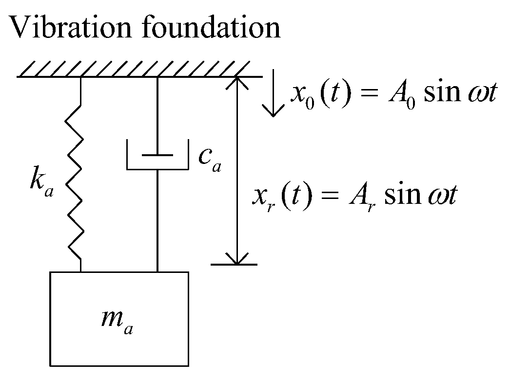
Figure 1. Auxiliary mass damper.
Preprints 100197 g001
Figure 2. Illustration of |meq| for ma = 1, ca = 1, and ka = 1.
Preprints 100197 g002
Figure 3. Rigidly connected Coulomb damper.
Preprints 100197 g003
Figure 4. A shaft excited by a periodic force.
Preprints 100197 g004
Figure 5. Simple pendulum.
Preprints 100197 g005
Table 1. Equivalent mass and damping of seven classes of fractional vibrators.
Fractional vibrations Equivalent mass Equivalent damping
Class I m eq 1 = m ω α 2 cos α π 2 c eq 1 = m ω α 1 sin α π 2
Class II m eq 2 = m ( 1 2 ς ω n ω β 2 cos β π 2 ) c eq 2 = c ω β 1 sin β π 2
Class III m eq 3 = ( ω α 2 cos α π 2 + 2 ς ω n ω β 2 cos β π 2 ) c eq 3 = m ω α 1 sin α π 2 + c ω β 1 sin β π 2
Class IV m eq 4 = m eq 1 c eq 4 = m ω α 1 sin α π 2 + k ω λ 1 sin λ π 2
Class V meq5 = m c eq 5 = k ω λ 1 sin λ π 2
Class VI m eq 6 = m eq 3 c eq 6 = c ω β 1 sin β π 2 + k ω λ 1 sin λ π 2
Class VII m eq 7 = m eq 2 c eq 7 = c eq 6
Table 2. Equivalent stiffness and damping ratio of seven classes of fractional vibrators.
Fractional vibrations Equivalent stiffness Equivalent damping ratio
Class I keq1 = k ς eq 1 = ω α 2 sin α π 2 2 ω n cos α π 2
Class II keq2 = k ς eq 2 = ς ω β 1 sin β π 2 1 c m ω β 2 cos β π 2
Class III keq3 = k ς eq 3 = ω α 1 sin α π 2 + 2 ς ω n ω β 1 sin β π 2 2 ω n ( ω α 2 cos α π 2 + 2 ς ω n ω β 2 cos β π 2 )
Class IV k eq 4 = k ω λ cos λ π 2 ς eq 4 = m ω α 1 sin α π 2 + k ω λ 1 sin λ π 2 2 m k ω α + λ 2 | cos α π 2 | cos λ π 2
Class V keq5 = keq4 ς eq 5 = ω n ω λ 2 1 sin λ π 2 2 cos λ π 2
Class VI keq6 = keq4 ς eq 6 = m ω α 1 sin α π 2 + c ω β 1 sin β π 2 + k ω λ 1 sin λ π 2 2 ( m ω α 2 cos α π 2 + c ω β 2 cos β π 2 ) k ω λ cos λ π 2
Class VII keq7 = keq4 ς eq 7 = c ω β 1 sin β π 2 + k ω λ 1 sin λ π 2 2 ( m c ω β 2 cos β π 2 ) k ω λ cos λ π 2
Table 3. Equivalent natural angular frequencies of seven classes of fractional vibrators.
Fractional vibrations Equivalent damping free natural angular frequency Equivalent damped natural angular frequency
Class I ω eqn 1 = ω n ω α 2 cos α π 2 ω eqd 1 = ω n ω α 2 cos α π 2 1 ω α sin 2 α π 2 4 ω n 2 | cos α π 2 |
Class II ω eqn 2 = ω n 1 c m ω β 2 cos β π 2 ω eqd 2 = ω n 1 c m ω β 2 cos β π 2 1 ς 2 ω 2 ( β 1 ) sin 2 β π 2 1 c m ω β 2 cos β π 2
Class III ω eqn 3 = ω n ( ω α 2 cos α π 2 + c m ω β 2 cos β π 2 ) ω eqd 3 = ω n 1 [ ( ω α 1 sin α π 2 + 2 ς ω n ω β 1 sin β π 2 ) 2 4 ω n 2 [ ( ω α 2 cos α π 2 + 2 ς ω n ω β 2 cos β π 2 ) ] ] 2 ( ω α 2 cos α π 2 + c m ω β 2 cos β π 2 )
Class IV ω eqn 4 = ω n ω λ cos λ π 2 ω α 2 cos α π 2 ω eqd 4 = ω n ω λ cos λ π 2 ω α 2 cos α π 2 1 ( m ω α 1 sin α π 2 + k ω λ 1 sin λ π 2 2 m k ω α + λ 2 | cos α π 2 | cos λ π 2 ) 2
Class V ω eqn 5 = ω n ω λ cos λ π 2 ω eqd 5 = ω n ω λ cos λ π 2 1 ( k ω λ 1 sin λ π 2 2 m k ω λ cos λ π 2 ) 2
Class VI ω eqn 6 = k ω λ cos λ π 2 ( m ω α 2 cos α π 2 + c ω β 2 cos β π 2 ) ω eqd 6 = k ω λ cos λ π 2 ( m ω α 2 cos α π 2 + c ω β 2 cos β π 2 ) 1 ( m ω α 1 sin α π 2 + c ω β 1 sin β π 2 + k ω λ 1 sin λ π 2 2 ( m ω α 2 cos α π 2 + c ω β 2 cos β π 2 ) k ω λ cos λ π 2 ) 2
Class VII ω eqn 7 = k ω λ cos λ π 2 m c ω β 2 cos β π 2 ω eqd 7 = k ω λ cos λ π 2 m c ω β 2 cos β π 2 1 ( c ω β 1 sin β π 2 + k ω λ 1 sin λ π 2 2 ( m c ω β 2 cos β π 2 ) k ω λ cos λ π 2 ) 2
Table 5. Logarithmic decrements and Q factors of seven classes of fractional vibrators.
Fractional vibrators Logarithmic decrement Q factor
Class I Δ eq 1 = π ω α 2 sin α π 2 ω n cos α π 2 1 ( ω α 2 sin α π 2 2 ω n cos α π 2 ) 2 Q eq 1 = ω n cos α π 2 ω α 2 sin α π 2
Class II Δ eq 2 = 2 π ς ω β 1 sin β π 2 1 c m ω β 2 cos β π 2 1 ( ς ω β 1 sin β π 2 1 c m ω β 2 cos β π 2 ) 2 Q eq 2 = 1 c m ω β 2 cos β π 2 2 ς ω β 1 sin β π 2
Class III Δ eq 3 = π ( ω α 1 sin α π 2 + 2 ς ω n ω β 1 sin β π 2 ) ω n ( ω α 2 cos α π 2 + 2 ς ω n ω β 2 cos β π 2 ) 1 ( ω α 1 sin α π 2 + 2 ς ω n ω β 1 sin β π 2 2 ω n ( ω α 2 cos α π 2 + 2 ς ω n ω β 2 cos β π 2 ) ) 2 Q eq 3 = ω n ( ω α 2 cos α π 2 + 2 ς ω n ω β 2 cos β π 2 ) ω α 1 sin α π 2 + 2 ς ω n ω β 1 sin β π 2
Class IV Δ eq 4 = 2 π m ω α 1 sin α π 2 + k ω λ 1 sin λ π 2 2 m k ω α + λ 2 | cos α π 2 | cos λ π 2 1 ( m ω α 1 sin α π 2 + k ω λ 1 sin λ π 2 2 m k ω α + λ 2 | cos α π 2 | cos λ π 2 ) 2 Q eq 4 = m k ω α + λ 2 | cos α π 2 | cos λ π 2 m ω α 1 sin α π 2 + k ω λ 1 sin λ π 2
Class V Δ eq 5 = 2 π k ω λ 1 sin λ π 2 2 m k ω λ cos λ π 2 1 ( k ω λ 1 sin λ π 2 2 m k ω λ cos λ π 2 ) 2 Q eq 5 = m k ω λ cos λ π 2 k ω λ 1 sin λ π 2
Class VI Δ eq 6 = π m ω α 1 sin α π 2 + c ω β 1 sin β π 2 + k ω λ 1 sin λ π 2 ( m ω α 2 cos α π 2 + c ω β 2 cos β π 2 ) k ω λ cos λ π 2 1 ( m ω α 1 sin α π 2 + c ω β 1 sin β π 2 + k ω λ 1 sin λ π 2 ) 2 4 [ ( m ω α 2 cos α π 2 + c ω β 2 cos β π 2 ) k ω λ cos λ π 2 ] Q eq 6 = ( m ω α 2 cos α π 2 + c ω β 2 cos β π 2 ) k ω λ cos λ π 2 m ω α 1 sin α π 2 + c ω β 1 sin β π 2 + k ω λ 1 sin λ π 2
Class VII Δ eq 7 = π c ω β 1 sin β π 2 + k ω λ 1 sin λ π 2 ( m c ω β 2 cos β π 2 ) k ω λ cos λ π 2 1 ( c ω β 1 sin β π 2 + k ω λ 1 sin λ π 2 ) 2 4 ( m c ω β 2 cos β π 2 ) k ω λ cos λ π 2 Q eq 7 = ( m c ω β 2 cos β π 2 ) k ω λ cos λ π 2 c ω β 1 sin β π 2 + k ω λ 1 sin λ π 2
Disclaimer/Publisher’s Note: The statements, opinions and data contained in all publications are solely those of the individual author(s) and contributor(s) and not of MDPI and/or the editor(s). MDPI and/or the editor(s) disclaim responsibility for any injury to people or property resulting from any ideas, methods, instructions or products referred to in the content.
Copyright: This open access article is published under a Creative Commons CC BY 4.0 license, which permit the free download, distribution, and reuse, provided that the author and preprint are cited in any reuse.
Prerpints.org logo

Preprints.org is a free preprint server supported by MDPI in Basel, Switzerland.

Subscribe

© 2024 MDPI (Basel, Switzerland) unless otherwise stated