1. Introduction
As unmanned vehicles such as quadcopters [
1,
2], fixed-wing [
3], unmanned ground vehicles [
4], and unmanned surface ships [
5] are widely used in various fields, the electromechanical equipment of these unmanned vehicles is becoming increasingly complex, and the tasks they undertake are becoming more and more diverse. However, intensive flight missions may induce fault that can lead to conflicts, collisions, and crashes. Therefore, for the expected growth of unmanned vehicle equipment, people are paying even greater attention to the reliability of autopilot system. As a life-critical system for unmanned vehicles, the reliability evaluation [
6] of the autopilot system is a significant research content for airworthiness testing.
In recent years, the hot research content such as sensor fault diagnosis(FD) [
7,
8], the fault tolerant control(FTC) [
9,
10] and prognostics and health management(PHM) [
11,
12] technology in the field of unmanned vehicles shows that the unmanned vehicle autopilot system is suffering from various types of faults, which revealing that the unmanned vehicle autopilot system still has considerable vulnerability. In order to efficiently verify the reliability of the autopilot system, a testing platform that can accomplish the fault simulation of the autopilot system has a very important role for the above research content. At present, the reliability assessment of most unmanned vehicle autopilot systems relies on the real-aircraft flight tests that inject a variety of faults during flight. Although the real-aircraft experimental method can genuinely reflect the actual situation, faults can only occur under specific conditions, and fatal faults will cause severe damage to unmanned vehicles. In addition, it is difficult to ensure the consistency of the faults under real-aircraft testing (to ensure that the same faults have the same fault action time and the same fault impact degree in multiple tests).
Hardware-in-the-loop(HIL) simulation [
13], as a very popular simulation method in recent years, can make up for the problems of randomness, consistency and repeatability that are difficult to be solved by real machine testing methods. The publicly released UAV simulation platforms can be categorized into two types: turntable platform and generic platform. As a typical representative of the rotary HIL simulation platform, the asymptotic tracking controller test platform proposed by Zhao [
14] et al. has outstanding advantages when attitude control and external factor interference are considered, but it is difficult to inject rich sensor fault types due to the use of actual unmanned vehicles. Generic platforms proposed by large tech companies or research teams, such as XTDrone [
15], Gazebo [
16], Jmavsim [
17], Airsim [
18], and FilghtGoggles [
19] are more concerned with the validation of control law algorithms and intelligent algorithms, and very few are able to simulate various types of faults and complete the reliability assessment of unmanned vehicle autopilot systems. A few other researchers, Gong [
20] et al. proposed a semi-physical simulation platform for UAV autopilot system to generate various fault data, but the platform pay more attention to the characteristics of the fault data realizations without considering the impact of the fault behavior on the whole system in depth. Khan [
21] et al. proposed a fault injection framework to simulate UAV flight and evaluated the reliability of the flight autopilot system undergo multiple GPS faults but did not consider other sensors in the hardware system. In addition, the above HIL platforms, besides failing to meet the strong demand for fault generation, also generally suffer from difficulties in adapting to different unmanned vehicles, compatibility problems between the software or hardware platforms of the autopilot system, and difficulties in meeting the low real-time performance brought about by the bandwidth of data transmission.
Field Programmable Gate Array(FPGA) [
22] are a special type of digital circuitry that is unique in that it can be programmed at the hardware level to perform specific logic functions. Compared to Application Specific Integrated Circuit(ASIC) in sensor chips, FPGA offer significant flexibility, parallel processing, and operating frequency advantages that make them a powerful tool in the field of chip-level design and verification [
23]. Thus, in this paper we simulate in FPGA the chip-level behavior of components of various sensor products of an autopilot system, including sensor outputs, and these simulated signals are subsequently used in flight control algorithms to ensure stability and correct response of the vehicle. Further, various flight conditions and sensor failure scenarios can be easily simulated with FPGA, which are very helpful in verifying the performance and robustness of sensor chips and autopilot systems under extreme conditions.
In this article, we propose a chip-level testing platform for reliability evaluation of unmanned vehicle autopilot systems, focusing on solving the generalized adaptability of the simulation platform as well as generating highly reliable sensor faults. The main research content and corresponding contributions are as follows:
- (1)
This paper proposes a multi-sensor digital modeling method for adapting to various UAV autopilot software platforms, which is divided into two parts: measurement model and communication modeling, and is verified on the FPGA platform. The simulation sensor model outputs the same digital signal as the real sensor product, realizing the interaction of sensing data between the simulation model and the autonomous driving hardware platform.
- (2)
This article proposes a coarse-grained failure model of inertial measurement unit(IMU), barometer, magnetic compass sensor and global position system(GPS) receiver under the action of multiple common failure factors for the necessary sensor chips of the autonomous driving hardware platform. Used to provide rich fault data for UAV health management research work.
- (3)
This article proposes a HIL platform for reliability verification of various autopilot systems, adapting to a variety of popular autonomous driving software platforms and hardware platforms as well as various types of UAV systems, including fixed-wing, multi-purpose Rotors, unmanned ships and unmanned vehicle systems. The platform has many excellent features such as high fidelity, ultra-high real-time performance, and black box testing.
2. Proposed HIL System Structure
In the study [
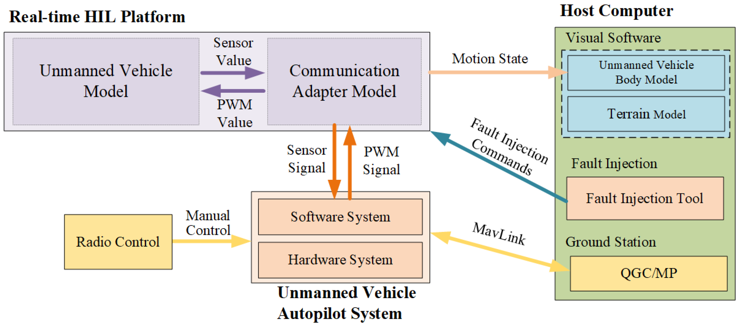
24], we introduced a standardized framework for UAV autopilot systems based on FPGA HIL simulation. Building upon this foundation, we propose a testing platform that dedicated to fault generation for autopilot sensor system. As shown in
Figure 1, the platform is divided into four parts: Real-time HIL Platform(RHILT), Unmanned Vehicle Autopilot System(UVAS), Host Computer(HC) and Radio Control(RC).
2.1. RHILT
It is primarily divided into two parts: system-on-chip(SoC) and FPGA. The SoC executes a mathematically complex unmanned vehicle model and employs the RT-Linux system to ensure synchronization of the model’s clock with the real-world clock. In contrast, the FPGA operates a high-frequency update communication adapter model to ensure the real-time nature of sensor communication. See
Section 3 for the details of the unmanned system model involved in this module. As well, the sensor model is discussed in detail in
Section 4.
Moreover, the PS sends flight simulation data packets at a higher frequency, including byte streams of the airframe type, location, attitude, etc. Concurrently, the PS possesses a fault injection interface that supports online modification of model parameters for the purpose of injecting faults.
2.2. UVAS
An UVAS consists of a control hardware system and a control software system, and the most popular open source platforms for the consumer market are listed in [
25]. In general, the hardware system is mainly used to provide the computational environment (embedded processor) and sense motion information (sensors), while the software system is mainly used to solve the control laws (Extended Kalman Filter algorithm) to achieve autonomous navigation control. For safety reasons, the software system will also include algorithms for fault-tolerant control, fault diagnosis and health management.
In order to ensure that the autopilot system can work properly on the proposed testbed, it is necessary to block (or remove) the on-board sensors in the hardware system and reconnect the autopilot system to the pins of the sensor chip simulated by the fpga system of the real-time simulation computer in order to receive the digital communication signals from the sensors. The above solution does not require any modification to the software system, which greatly protects the controller software algorithm from being leaked, and is of practical significance for black-box testing of different autopilot products from different UAV companies.
2.3. HC
The mainframe is tasked with running the application. The following three applications are included.
- (1)
The vision software uses the latest unreal engine 5 to render flight simulation animations, and the simulation model of the UAV frame and terrain environment (including obstacles) can simulate the objective world with a high degree of realism. It receives flight simulation data in real time to determine the UAV attitude and position and other dynamic performance characteristics. At the same time, the fault injection effect can be qualitatively assessed by observing the UAV flight process.
- (2)
The fault injection tool is used to trigger fault generation online. In this test method, engineers add fault test cases by setting fault modes, fault durations and fault intensities to simulate various fault cases that may occur in the sensor system.
- (3)
On the one hand, the ground station formulates automatic test tasks (such as cruising, level flight, or hovering), and on the other hand, it monitors sensor data in real time to quantitatively evaluate the fault injection effect.
2.4. RC
As an optional tool, the RC has the same mission planning functions as the ground station. Engineers can manually control the movement of the unmanned vehicle to the desired state and complete some difficult flight actions (such as yaw, roll extreme sports, etc.).
3. Unmanned Vehicle Model
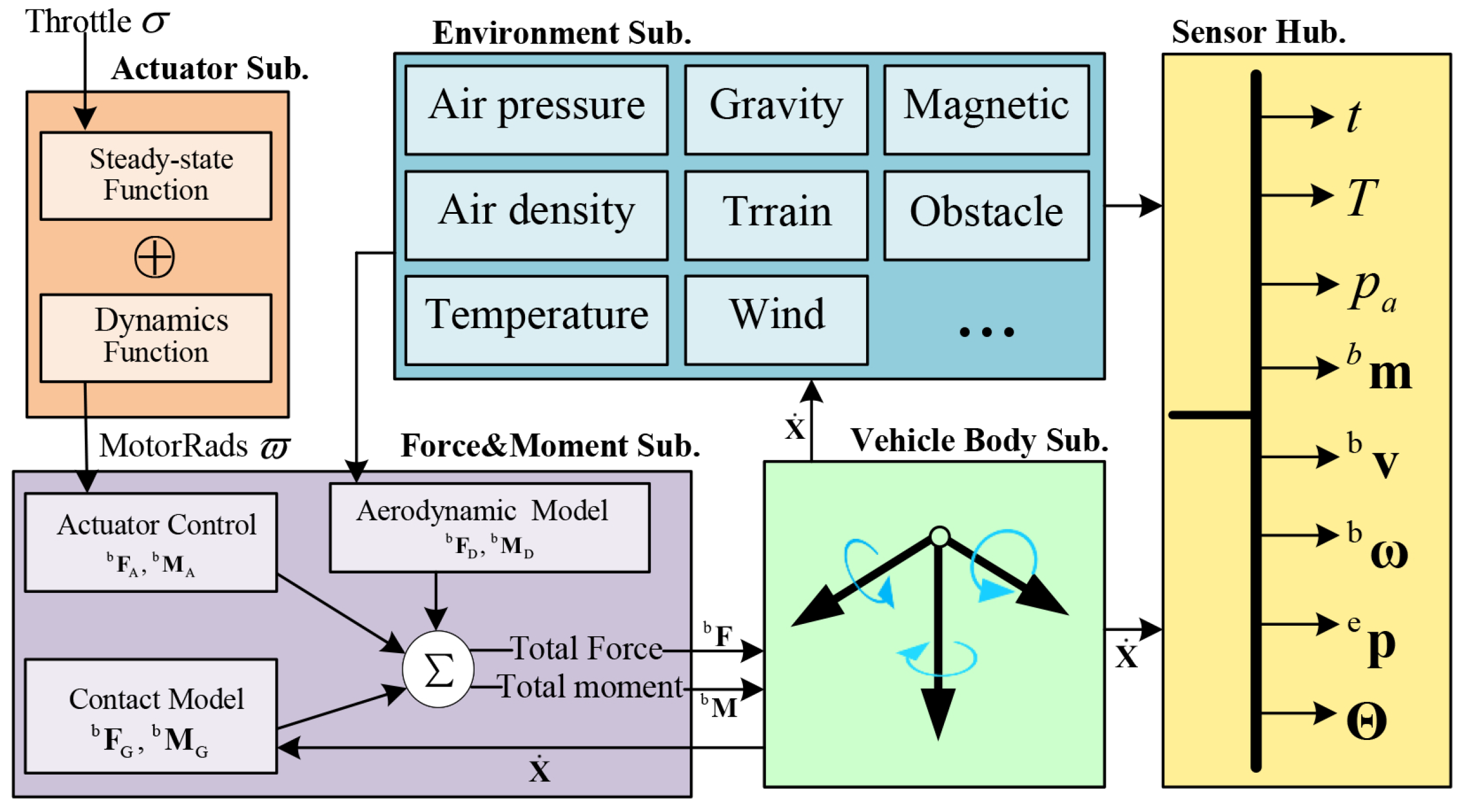
The unmanned vehicle model mainly describes the dynamic and kinematic motion process of the unmanned vehicle in the working environment. A complex unmanned vehicle model can be regarded as composed of several small subsystems, as shown in
Figure 2, including actuator subsystem, environment subsystem, force and moment subsystem, vehicle body subsystem and Sensor Hub.
The actuator subsystem is the primary power source of control unmanned vehicles, but the accurate power model is extremely complex. From the control efficiency and the general characteristics of the motor system, the transfer function of the simplified model of the power unit is given as follows
where
i is the sequence number of the actuator,
is the motor speed,
is the throttle command that is equal to the PWM value,
is the motor dynamic response time constant,
and
are constant parameters that can be obtained from the website
1. Then, the driving force
and driving torque
generated by the actuator are
where
is the control efficiency matrix taking into account the different rack layouts.
The support forces
and support moments
from the ground during take-off and landing, as well as the aerodynamic resistance
and damping moments
during flight, are also considered in depth. The total force
and moment
of the unmanned carrier is expressed as
The unmanned vehicle provides the necessary force and moment to control the position and attitude of the system through its actuators. A six-degree-of-freedom(6DOF) model can describe the motion of any unmanned vehicle. Define unmanned vehicle flat Earth position as
, flight speed vectors in body-fixed axes concerning body frame as
, likewise in the flat Earth reference frame as
, angular rates vectors in body-fixed axes as
, body euler angle as
. The dynamic and kinematic characteristics of the unmanned vehicle can be described as follows
where
t is real time factor,
,
is the next state estimate,
is the PWMs vector from the output of the autopilot system.
Inspired by the works presented in [
26], the rigid motion law of the unmanned vehicle can be expressed by differential equations, including force and moment equations, navigation equations, and motion equations.
where
is the rotation matrix from the body-fixed frame to the earth inertia frame,
is
skew symmetric form,
is a matrix shorthand,
is the moment of inertia,
and
are the vectors of external forces and moment, respectively, satisfying the following:
where
,
and
denote
,
and
, respectively.
4. Sensor Digital model
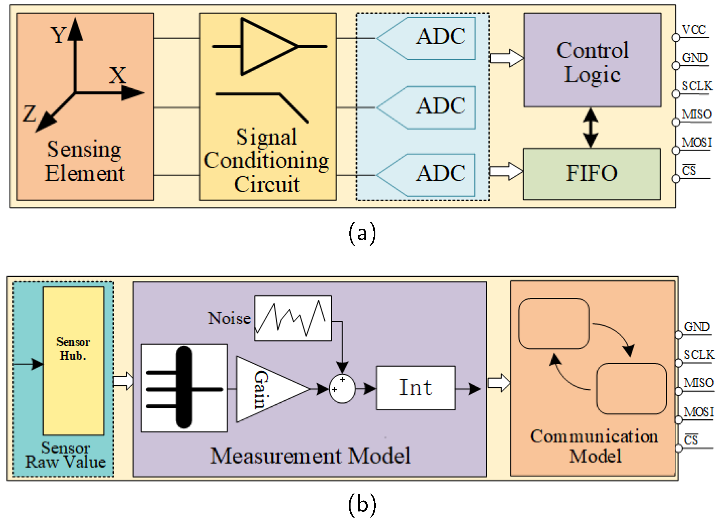
In consumer electronics, manufacturers favor high-performance MEMS sensors. For example, IMU sensors use the piezoelectric or Coriolis effect to detect changes in motion, and the workflow as shown in
Figure 3a includes signal amplification, digitization, and data communication control logic. In order to simulate actual flight testing of an autopilot system on the HIL platform, a sensor simulation workflow as shown in
Figure 3b is recommended. This simulation generates raw sensor data, adjusts the data to meet the requirements of the autopilot software through scaling and conversion, and simulates the data transfer using appropriate communication protocols.
4.1. Sensor Data Source
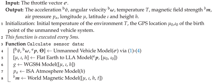
The types of sensor data are diverse. The first type of sensor data is to perceive its own attitude, such as acceleration and angular velocity, which can be calculated by the 6DOF model; The second type of sensor data is related to working environment factors, such as temperature, air pressure and magnetic field strength, these require the use of standard modules with high reliability; The third type of sensor data is observation, such as the longitude, latitude and altitude data required for GPS positioning, which need to be converted between different reference systems. The program of calculating the sensor raw data is as shown in Algorithm 1. It is worth mentioning that the Flat Earth to LLA Model, WGS84 Model, ISA Atmosphere Model and World Magnetic Model from lines 5 to 8 in Algorithm 1 are standard library models [
27].
|
Algorithm 1: Calculate sensor data |
 |
4.2. Measurement Model
4.2.1. IMU Model
The output of the MEMS IMU are affected by many error sources, such as scale factor errors, biases, and random drift. In the field of inertial navigation, the acceleration and angular velocity measurements of the IMU [
28] can be expressed as:
where
and
are the real values of the acceleration and angular velocity in the body frame, respectively. Furthermore,
and
are defined as follows:
where the diagonal elements
and
of the
and
matrix are the acceleration and angular velocity scale factor errors respectively.
are the six installation error angles between the accelerometer frame a and the body frame b;
are the six installation error angles between the gyro frame g and the body frame b;
and
denotes the acceleration zero bias and angular velocity zero bias respectively;
and
denotes the acceleration rate noise and angular velocity rate noise respectively, assumed to be Gaussian white noise [
29] with characteristics
where
is the white noise variance coefficient,
is the sampling rate. The zero bias
and
will change with time and can be established as a first-order Markov process
with characteristics
where the noise driving the bias
, time constant
, bias variation
can be determined by Allan variance and autocorrelation analysis.
Considering the lever-arm effect due to the fact that the accelerometer is not at the center of gravity, the accelerometer true vector is
where,
represents the distance between the IMU installation position and the center of gravity position. Beside,
.
The dynamic characteristics of a tri-axis sensor are generally expressed by a second-order programming transfer function [
30] as
where,
denotes the natural frequency,
denotes the damping ratio, and
denotes the time constant.
4.2.2. Compass Model
Because they are both three-axis sensors, magnetic compasses have similar measurement models and dynamic transfer functions to accelerometers or magnetometers, which are expressed as
where
denotes scale factors and misalignment error,
is the zero bias,
is the rate noise, which have the same statistical characteristics as (
8) and (
10). And it has the same dynamic characteristics as (
12).
4.2.3. Barometer Model
The barometer is a typical uniaxial sensor which measures physical quantities without multi-channel characteristics, and its measurement model is expressed as follows
where
is the pressure altitude measurement value,
is the true air pressure height,
is the barometer drift error which has the same Gaussian white noise characteristics as (
8), and
is the barometer wind disturbance error [
31] which are expressed as
where
(the capital letter
K is the temperature unit of Kelvin) is the standard sea level temperature,
is the temperature lapse rate constant,
is the standard sea level pressure,
g is the gravity acceleration constant,
is the air constant,
is the standard air density,
is the measured air pressure value after wind interference,
is the wind speed.
4.2.4. GPS Receiver Model
In contrast to the aforementioned three types of MEMS measurement sensors, GPS receivers are classified as calculation sensors which receive multiple satellite signals and then calculate the position of the node in the earth Latitude-Longitude-Altitude (LLA) global coordinate.
Define the node position measurement with respect to the Earth fixed coordinate system as
. The measurement model for calculating the position of a node by the GPS receiver [
32] is expressed as
where
denotes the transformation from Flat Earth to LLA,
is the measurement noise induced by the communication channel with the satellite, which can also be described by the same Gaussian white noise model as (
8).
Define the node velocity measurement with respect to the Earth fixed coordinate system as
. The measurement model for calculating the velocity of a node by the GPS receiver is expressed as
where
f is the measurement noise of the velocity caused by the flying perturbation.
4.3. Communication Adapter Model
In the autopilot system, critical sensors perform efficient data transfer with the processor via board-level communication buses, which involve communication interface protocols such as serial peripheral interface (SPI), inter-integrated circuit (IIC), and universal asynchronous transceiver (UART). In the proposed HIL platform, the communication adapter model simulates the digital control logic unit of the actual sensor chip to enable the conversion of sensor data into binary digital signals suitable for board-level transmission.
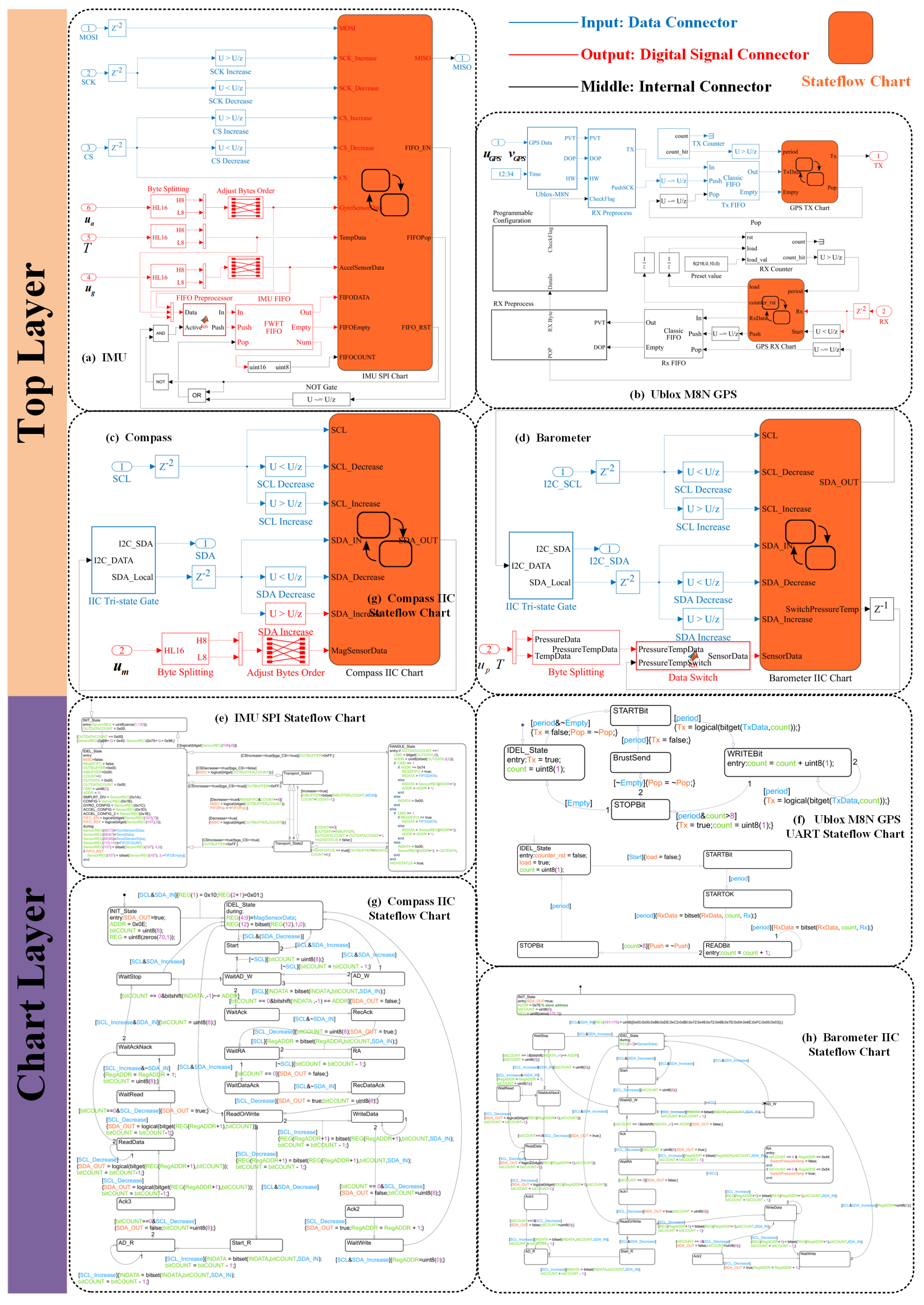
Here, we take the sensor products in Pixhawk4 as an example to describe the model of the sensor adapter in detail. The names of the various types of sensor products in the Pixhawk4 autopilot system are as follows: the IMU is ICM20689, the magnetic compass is IST8310, the barometer is MS5611 and the GPS receiver is Ublox M8N GPS. The simulation model of the above four sensor sensors based on the finite state machine(FSM) modeling approach as shown in
Figure 4. The model is divided into two major phases: data processing and analogue communication. The data processing phase includes functions such as data type conversion, byte splitting, and FIFO storage, while the analogue communication phase covers response mechanisms such as chip identification, programmable register configuration, and data transmission. For this complex control logic process, the model adopts a finite state machine-based approach to modeling, which ensures the high efficiency of the communication process and the reliability of the system.
5. Sensor Fault Model
Fault is a common phenomenon in which the characteristics or parameters of an electronic equipment system deviate beyond the acceptable range, thereby degrading the performance of the system. The possible malfunction behavior of the autopilot system is concentrated on the sensors.
5.1. Measurement Model Fault Scheme
5.1.1. Scale Fault
As the sensor is exposed to harsh environmental conditions (such as high temperature, high humidity, strong magnetic field, strong corrosion, etc.), the performance of the sensor material may be changed and degraded, resulting in distortion in the output of electronic devices such as transistor resistance, capacitance and inductance in the chip circuit. The scale fault output is shown as sensor data scaling, the fault scheme
is represented as
where
indicates the proportional fault factor,
j can be replaced by the characters
.
5.1.2. Bias Fault
Sensor bias faults often arise from several causes, such as component aging or damage, temperature effects, power supply variations, mechanical stress or damage, calibration mistakes, and environmental factors like magnetic fields, humidity, or chemical interference. These factors, individually or in combination, cause the sensor output to deviate from the true value by a fixed amount over the entire measurement range, the fault scheme
is represented as
where
indicates the bias fault factor.
5.1.3. Drift Fault
Sensor drift faults are the gradual deviation of a sensor’s output from the true value over time, caused by material aging, environmental influences like temperature and humidity, and mechanical wear of components like ADCs and amplifiers. Drift represents a continuous, cumulative change in output, distinct from fixed offsets or proportional changes. For example, a temperature-affected sensor may gradually change its output due to changes in material properties with temperature, or a sensor subjected to mechanical stress over a long period of time may experience a gradual deviation of the output signal from the initial calibration point due to small changes in physical form. The measured signal
of a drift fault scheme is expressed as
where
is the drift fault factor,
is the occur time.
5.1.4. Noise Fault
Sensor noise faults involve undesired random fluctuations in output, caused by external electromagnetic interference, internal electronic noise like thermal or shot noise, and environmental factors such as mechanical vibrations and temperature changes, particularly in sensitive sensors. The noise fault scheme
is represented as
where
is the noise fault gain factor,
is the noise fault model.
5.1.5. Spike Fault
Sensors with microstructures like cantilevers and membranes can degrade or fail from external shocks, causing ruptures or detachment from anchor points, potentially leading to short circuits or performance issues. For instance, excessive pressure can rupture micro-membranes, and strong impacts can misalign internal elements, like causing a mass block in accelerometers to touch electrodes. Severe impacts may also damage tiny circuits and solder joints, affecting signal transmission and processing. And the spike fault can be regarded as a special form of scale fault, when the amplitude
is as large as possible and the spike fault duration time
is as small as possible, it can be described as follows
where
indicates a very small time.
5.2. Communication Model Fault Scheme
5.2.1. Noise Fault
Due to the short distance communication, the sensor communication circuit uses a baseband digital circuit, that is, transmits high-level or low-level signals representing binary digital logic “0” or “1”. The widely used transistor-transistor-logic(TTL) and complementary metal-oxide-semiconductor(CMOS) digital integrated circuit(IC) devices are affected by the characteristics of materials, effect of proton radiation [
33], high-energy particles, etc., so the communication circuit does not have the ideal electrical signal characteristics, but parasitics a considerable amount of interference signals. The
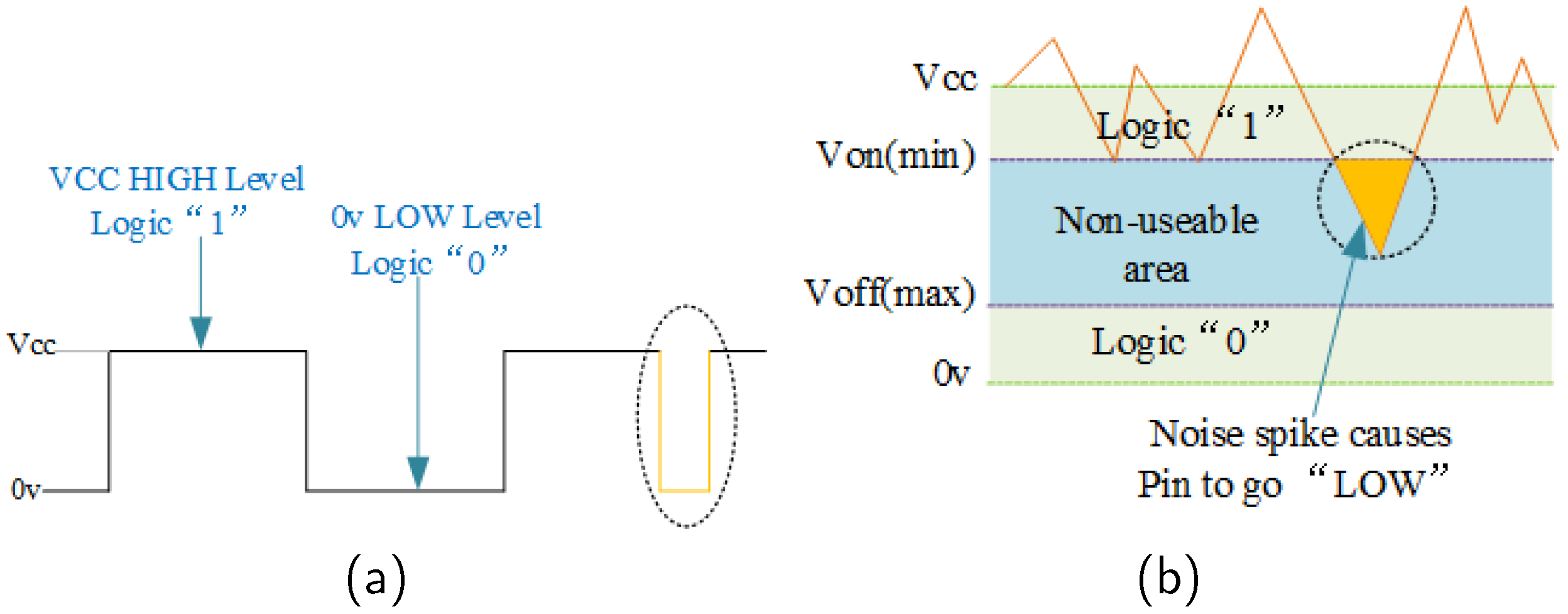
Figure 5 illustrates the general interference phenomena in digital communication circuits. For different digital circuits, the low-level interval of
is generally defined as digital logic “0”, and the high-level interval of
is defined as digital logic “1”. However, there is a “Non-useable area” between
and
, and the level signal falls in this area. Digital circuit logic interpretation will become unpredictable.
Figure 5a shows a segment of digital signal that is disturbed by noise. The noise signal in
Figure 5b is superimposed on the
supply voltage, the voltage signal is kept above the minimum level
, and the digital circuit logic interpretation will not be affected. But when the noise level becomes sufficiently large and the noise spike causes the high voltage level to drop below this lowest level, the digital circuit may interpret this spike as a logical “0”. When the noise impact fault occurs, the level signal of the pin is a randomly varying 0 or 1, and the fault model is as follows
where
is the sensor chip pin digital signal,
n is the sampling time.
5.2.2. Open Circuit Fault
Sensor open-circuit faults typically result from a break in the circuit path, caused by physical damage to wires or solder joints, environmental corrosion, or damage to internal components from overheating or voltage issues, preventing current flow. Sensor open circuit faults can be represented as
where & denotes
operation sign, when
there is no fault, while when
it indicates an open-circuit fault.
5.2.3. Short Circuit Fault
Sensor short-circuit failures occur when an unintended conductive path redirects current flow, caused by insulation damage, moisture intrusion, external conductive materials like metal shavings, or internal component damage due to over-voltage, overheating, or physical shock. Sensor short circuit faults can be represented as
where | denotes
operation sign, when
there is no fault, while when
it indicates an open-circuit fault.
5.3. Fault Inject Progress
Above all, we obtain the sensor measurement model fault parameters and communication model fault parameters, and the sensor measurement values with fault modes are further expressed as
where
represents the node measurement value before the drift fault processing unit in the signal chain of the measurement model. Likewise, the sensor communication digital signal with failure mode is further expressed as
where
represents the measurement value of the intermediate node in the communication model signal chain.
In addition, according to the form of fault existence, it can be divided into intermittent faults and permanent faults, which shows that faults have a time dimension. Therefore, the fault duration time needs to be fully considered when designing the failure mode, indicating that the sensor is in an unhealthy state during this period.
We can develop a test case library necessary for the fault injection process based on engineers’ development and testing experience and civil aircraft airworthiness test items and evaluation indicators. In order to form a standard test process, we stipulate that each test case command sequence needs to set the fault injection
trigger time ,
test stop time , expected
sensor fault components,
fault impact factors as well as
flight tasks, etc. Therefore, we can achieve the purpose of injecting faults online by modifying the fault model parameters.And the software and hardware platforms involved, are shown in
Table 1.
6. Experiments and Verification
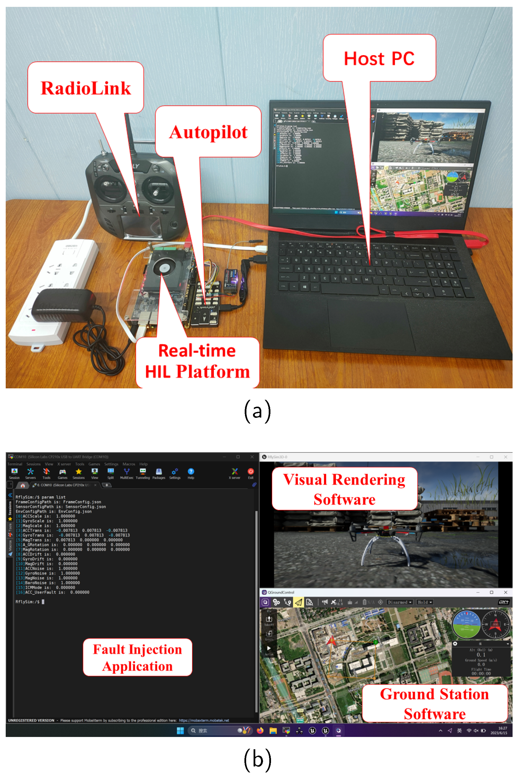
In this section, we design an MPSoC-FPGA-based HIL platform shown in the
Figure 6 to fulfill the functional requirements of the testbed. First, we develop and validate the unmanned vehicle model, sensor model and fault model in Simulink and Stateflow environments based on the MBD modeling approach. Then the embedded code of each model is generated by the automatic code generation tool, followed by adding the fault injection interface and simulation data sending interface program in the IDE. Finally, the executables are cross-compiled and imported into the testbed device to run. In terms of performance, the platform uses two ARM-A53 1.2GHz cores to ensure that the unmanned vehicle model, the sensor measurement model and its part of the fault model computation results are accurate and up to 2KHz running frequency, and uses FPGA 100MHz to ensure that the sensor communication model and its part of the fault model ultra-high update frequency requirements.
6.1. HIL Platform Function Verification
The most distinctive feature of the proposed HIL platform is to simulate the working mode of actual sensor products. In the case of the flight autopilot system, data interaction with sensors through digital communication is the same as the workflow of natural flight. The solution adopted in this paper removes the limitation of general hardware in the loop simulation scheme, so it has broader support. The functional verification of platform suitability was carried out from three aspects: flight control software platform, flight control hardware platform and unmanned system type.
We selected a number of representative hardware and software platforms that are widely used in scientific research and commercial fields for experimental verification. As shown in
Figure 7, we selected two hardware platforms, PX4 and APM, and three hardware platforms, Holybro Pixhawk 4, CubePilot Cube Orange, and FEISILAB ZYH7. The two critical points of the HIL platform to adapt different kinds of flight controllers are as follows: the software platform modifies configuration options to select the access mode of sensors as external, and it is necessary to shield internal sensors. The hardware platform needs to reserve the necessary communication interface, optional with multi-function carrier board.
We established a variety of analytical models of unmanned systems, including multi-rotor model, fixed wing model, unmanned ship model and unmanned vehicle model, and completed the adaptation verification of the above four unmanned systems. This work shows that the proposed platform can be easily compatible with a variety of typical unmanned systems.
6.2. Simulation Reliability Assessment
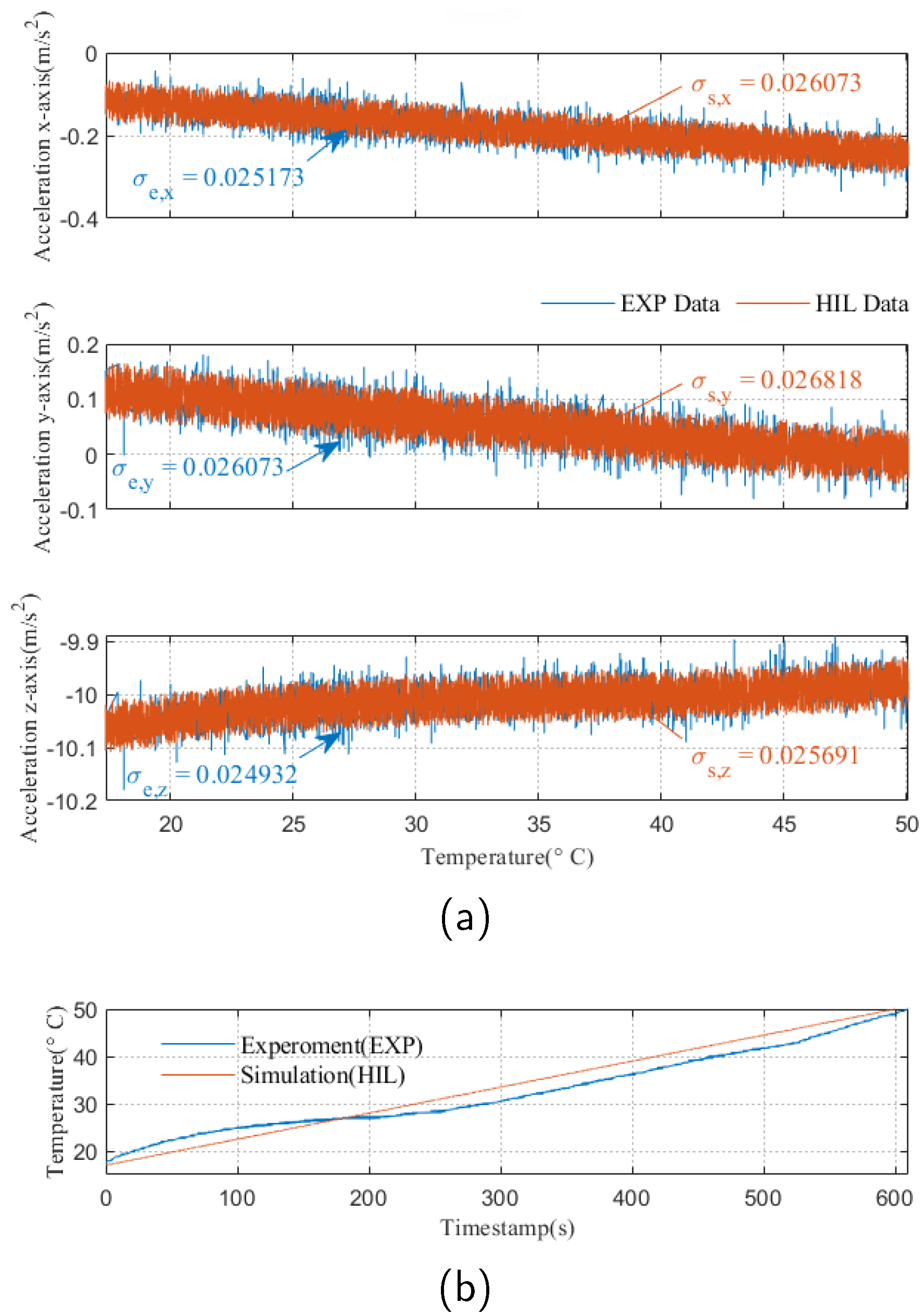
To verify the reliability of the HIL platform, experiments and simulations are performed with accelerometer temperature drift fault test presented in
Figure 8a. In the horizontal static environment, we obtained the acceleration values of x-axis, y-axis and z-axis of the ICM20689 sensor onboard the Pixhawk4 autopilot under the temperature variation range of
are presented as the ‘EXP Data’ curve in
Figure 8b, from which it can be clearly observed that the accelerometer appears drift fault phenomenon with the change of temperature.
From the data curve, the curves of simulation and experiment are highly coincident, which reveals the performance ability of HIL platform to simulate real fault behavior. Further, we adopted the evaluation method in literature [
34] to quantitatively analyze the HIL reliability. We choose the performance credibility index
here. The root mean square error
is selected as the performance parameter, the threshold parameter
and the the simulation error for each axis is
. In the expectation of achieving a desired passing mark
, the credibility evaluation index
was calculated as followed
where
i represents the x-axis, y-axis and z-axis. Then, the simulation credibility for each period
is obtained with the results listed in the
Table 2. By combining accelerometer x-axis, y-axis, and z-axis credibility indices, the average simulation credibility is
. Since the obtained credibility index
is far above the passing mark
, the simulation results can be considered as credible as experimental results.
6.3. Proposed Platform Application
6.3.1. Fault Generation
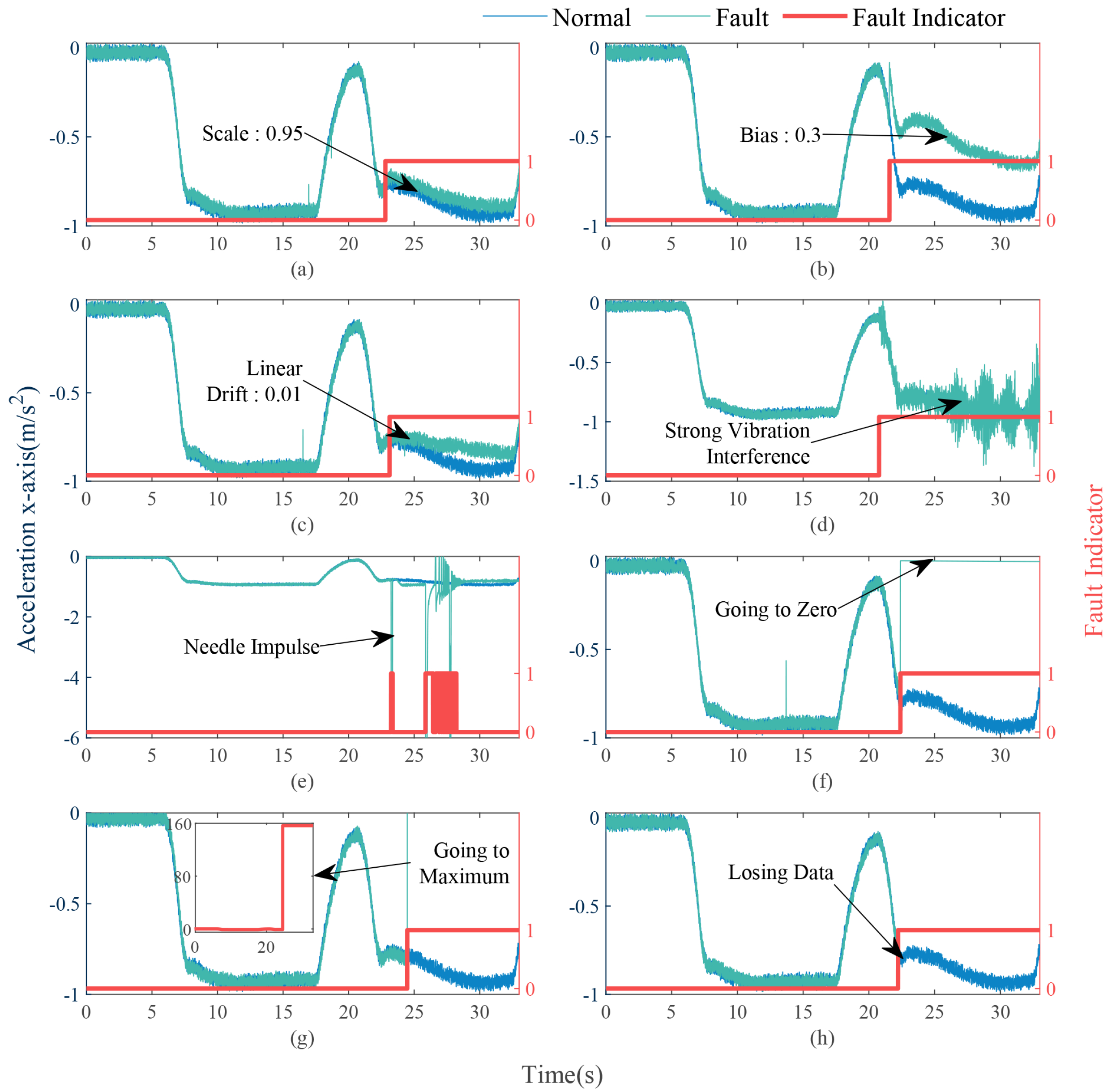
Multiple UAV flight missions are planned in the HIL platform, then injecting scale fault, bias fault, drift fault, noise fault, spike fault, internal open-short circuit fault for sensitive element, and open/short-circuit for the communication circuit into the accelerometer during the flight, as shown in
Figure 9, we choose a simple expert model to perform fault identification and health assessment on fault data. It is worth noting that fault diagnosis and health assessment algorithms are not the core content of this article. This application case shows that test cases with multiple sensors, multiple failure modes, and different fault impact levels can be injected into the proposed HIL platform. The outstanding contribution of this work is that we can provide high-quality and large-scale test data for health management research work.
6.3.2. Reliability Testing
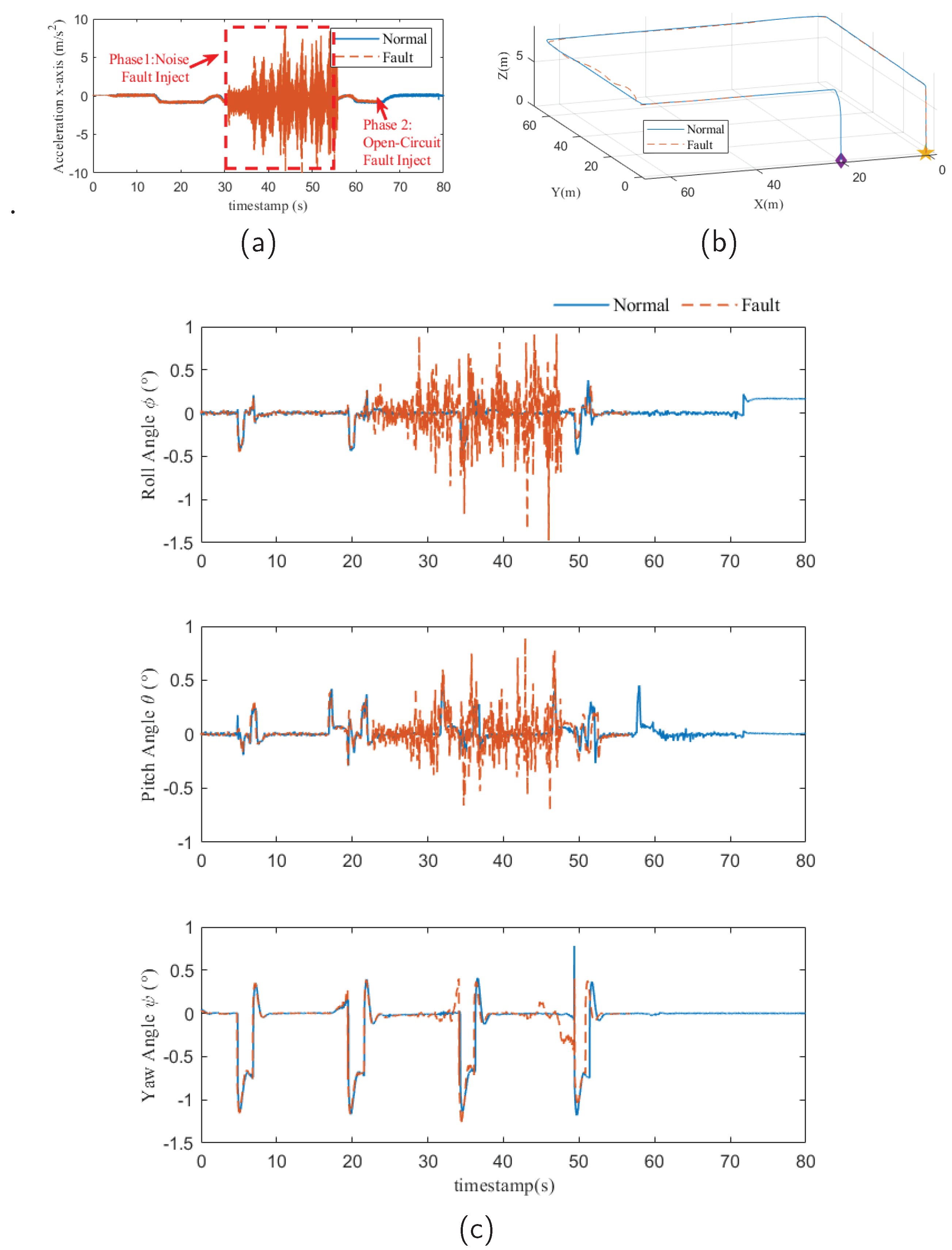
Here we present a study case of a UAV reliability flight. The autonomous flight mission shown in
Figure 10b is scheduled in the HIL platform, then the accelerometer noise fault and open-circuit fault for communication circuit are injected successively in the fight mission. The data recorded by the HIL platform is shown in
Figure 10, and the fault effect is shown in
Figure 10a. The position and attitude of the drone are shown in
Figure 10b. The test results as shown in
Figure 10c presented the noise fault caused the drone body to undergo severe vibration and had a certain impact on the scheduled mission. On the other hand, the drone did not lose control due to severe noise fault, which shows that the tested unmanned system software platform has strong anti-noise performance; However, when the accelerometer suffered an open-circuit fault, the drone crashed immediately, causing huge damage to the fuselage. This shows that the unmanned system under test did not have hardware redundancy design.
This application case shows that we can perform reliability testing of unmanned systems on the proposed HIL platform in a low-cost and efficient manner. When the unmanned system model is sufficient and the fault model is rich enough, in theory, the relevant testing work of any unmanned system can be completed on the proposed HIL platform. In addition, since the proposed HIL platform supports complete flight testing and fault injection, it can also perform fault tolerant control of dynamic systems, and the research work [
35] has been well verified.
6.4. Videos and Source Code
The video gives an overall introduction to the test platform and an operational demonstration of fault generation, using the PX4 software platform, Pixhawk4 hardware platform and DJi F450 quadcopter drone:
We have released the Matlab/simulink code:
Engineers can easily adapt to the target open source platform by simply modifying the unmanned vehicle model and sensor model parameters.
7. Conclusions
Aiming at the demand of reliability verification of automatic driving system, this paper proposes an economical and practical HIL platform. In this paper, coarse-grained simulation models of various sensor products for unmanned vehicle and autopilot systems are first given. Then, the multi-mode failure models of various sensors are further given, which can realize credible chip-level failure simulation. Finally, the design and development of the HIL platform is completed on the MPSoC-FPGA development board, and the compatibility, accuracy and functionality of the HIL platform are further verified. The results show that the HIL platform proposed in this paper has outstanding advantages in intelligent unmanned control system. Future work will focus on refining various behavioral-level fault models so as to provide a richer library of fault use cases.
Author Contributions
Conceptualization, X.D.; methodology, X.D. and R.F.; software, X.D. and R.F.; validation, X.D. and R.F.; formal analysis, X.D. and R.F.; investigation, X.D. and R.F.; resources, X.D. and R.F.; data curation, X.D. and R.F.; writing—original draft preparation, R.F.; writing—review and editing, X.D. and R.F.; visualization, X.D. and R.F.; supervision, X.D. and R.F.; project administration, X.D.; funding acquisition, X.D. All authors have read and agreed to the published version of the manuscript.
Funding
This research was funded by the National Key Project of Research and Development Plan of China under Grant 2021ZD0140301.
Data Availability Statement
Conflicts of Interest
The authors declare no conflicts of interest.
References
- Dai, X.; Quan, Q.; Ren, J.; Cai, K.Y. An Analytical Design-Optimization Method for Electric Propulsion Systems of Multicopter UAVs With Desired Hovering Endurance. IEEE/ASME Trans. Mechatron. 2019, 24, 228–239. [Google Scholar] [CrossRef]
- Asignacion, A.; Satoshi, S. Historical and Current Landscapes of Autonomous Quadrotor Control: An Early-Career Researchers’ Guide. Drones 2024, 8. [Google Scholar] [CrossRef]
- Baldi, S.; Roy, S.; Yang, K.; Liu, D. An Underactuated Control System Design for Adaptive Autopilot of Fixed-Wing Drones. IEEE/ASME Trans. Mechatron. 2022, 27, 4045–4056. [Google Scholar] [CrossRef]
- Shen, K.; Wang, M.; Fu, M.; Yang, Y.; Yin, Z. Observability Analysis and Adaptive Information Fusion for Integrated Navigation of Unmanned Ground Vehicles. IEEE Trans. Ind. Electron. 2020, 67, 7659–7668. [Google Scholar] [CrossRef]
- Raber, G.T.; Schill, S.R. Reef Rover: A Low-Cost Small Autonomous Unmanned Surface Vehicle (USV) for Mapping and Monitoring Coral Reefs. Drones 2019, 3. [Google Scholar] [CrossRef]
- Xing, L.; Johnson, B.W. Reliability Theory and Practice for Unmanned Aerial Vehicles. IEEE Internet Things J. 2023, 10, 3548–3566. [Google Scholar] [CrossRef]
- He, K.; Yu, D.; Wang, D.; Chai, M.; Lei, S.; Zhou, C. Graph Attention Network-Based Fault Detection for UAVs With Multivariant Time Series Flight Data. IEEE Trans. Instrum. Meas. 2022, 71, 1–13. [Google Scholar] [CrossRef]
- Yang, P.; Geng, H.; Wen, C.; Liu, P. An Intelligent Quadrotor Fault Diagnosis Method Based on Novel Deep Residual Shrinkage Network. Drones 2021, 5. [Google Scholar] [CrossRef]
- Ma, Z.; Gong, H.; Wang, X. Fault-Tolerant Event-Triggrred Control for Multiple UAVs with Predefined Tracking Performance. Drones 2024, 8. [Google Scholar] [CrossRef]
- Nguyen, N.P.; Pitakwatchara, P. Attitude Fault-Tolerant Control of Aerial Robots with Sensor Faults and Disturbances. Drones 2023, 7. [Google Scholar] [CrossRef]
- Zhongyi, C.; Zezhou, W.; Keqiang, X.; Shaoliang, L.; Bingye, Y. Health index construction and remaining useful lifetime prediction of aviation products based on multi-source degradation data fusion. 2022 Glob. Reliab. Progn. Health Manag. Conf., PHM-Yantai, 2022, pp. 1–5. [CrossRef]
- Xu, J.; Wang, Y.; Xu, L. PHM-Oriented Integrated Fusion Prognostics for Aircraft Engines Based on Sensor Data. IEEE Sensors J. 2014, 14, 1124–1132. [Google Scholar] [CrossRef]
- Wang, Y.; Wang, X.; Shen, L. Approximate Optimal Curve Path Tracking Control for Nonlinear Systems with Asymmetric Input Constraints. Drones 2022, 6. [Google Scholar] [CrossRef]
- Zhao, B.; Xian, B.; Zhang, Y.; Zhang, X. Nonlinear Robust Adaptive Tracking Control of a Quadrotor UAV Via Immersion and Invariance Methodology. IEEE Trans. Ind. Electron. 2015, 62, 2891–2902. [Google Scholar] [CrossRef]
- Xiao, K.; Tan, S.; Wang, G.; An, X.; Wang, X.; Wang, X. XTDrone: A Customizable Multi-rotor UAVs Simulation Platform. 2020 4th Int. Conf. Robot. Autom. Sci., ICRAS, 2020, pp. 55–61. [CrossRef]
- Khaliq, S.; Ahsan, S.; Nisar, M.D. Multi-Platform Hardware In The Loop (HIL) Simulation for Decentralized Swarm Communication Using ROS and GAZEBO. 2021 Proc. - IEEE Int. Symp. World Wirel., Mob. Multimed. Networks, WoWMoM, 2021, pp. 310–315. [CrossRef]
- Bahl, N.; Sahu, P.; Sharma, P.; Gautam, P.; Singh, A.; Srivastava, A. Design of an Autonomous UAV for Racing Applications. 2022 8th Int. Conf. Signal Process. Commun., ICSC 2022, 2022, pp. 91–96. [Google Scholar]
- Szolc, H.; Kryjak, T. Hardware-in-the-loop simulation of a UAV autonomous landing algorithm implemented in SoC FPGA. 2022 Signal Process. - Algorithms, Architect., Arrange., Appl. Conf. Proc., SPA, 2022, pp. 135–140. [CrossRef]
- Guerra, W.; Tal, E.; Murali, V.; Ryou, G.; Karaman, S. Flightgoggles: A modular framework for photorealistic camera, exteroceptive sensor, and dynamics simulation. arXiv preprint arXiv:1905.11377 2019. [CrossRef]
- Gong, S.; Meng, S.; Wang, B.; Liu, D. Hardware-In-the-Loop Simulation of UAV for Fault Injection. 2019 Progn. Syst. Heal. Manag. Conf., PHM-Qingdao, 2019, pp. 1–6. [CrossRef]
- Khan, A.; Ivaki, N.; Madeira, H. Are UAVs’ Flight Controller Software Reliable? 2022 IEEE 27th Proc. IEEE Pac. Rim Int. Symp. Dependable Comput., PRDC 2022. IEEE, 2022, pp. 194–204. [CrossRef]
- Tsmots, I.; Teslyuk, V.; Łukaszewicz, A.; Lukashchuk, Y.; Kazymyra, I.; Holovatyy, A.; Opotyak, Y. An Approach to the Implementation of a Neural Network for Cryptographic Protection of Data Transmission at UAV. Drones 2023, 7. [Google Scholar] [CrossRef]
- Hosseinabadi, A.H.H.; Black, D.G.; Salcudean, S.E. Ultra low-noise FPGA-based six-axis optical force–torque sensor: Hardware and software. IEEE Transactions on Industrial Electronics 2020, 68, 10207–10217. [Google Scholar] [CrossRef]
- Dai, X.; Ke, C.; Quan, Q.; Cai, K.Y. RFlySim: Automatic test platform for UAV autopilot systems with FPGA-based hardware-in-the-loop simulations. Aerosp. Sci. Technol. 2021, 114, 106727. [Google Scholar] [CrossRef]
- Ebeid, E.; Skriver, M.; Terkildsen, K.H.; Jensen, K.; Schultz, U.P. A survey of open-source UAV flight controllers and flight simulators. Microprocess. Microsy. 2018, 61, 11–20. [Google Scholar] [CrossRef]
- Quan, Q., Dynamic Model and Parameter Measurement. In Introduction to Multicopter Design and Control;
Springer Singapore: Singapore, 2017; pp. 121–143 [CrossRef]
- Agency, D.M. Department of Defense World Geodetic System 1984: its definition and relationships with local geodetic systems. Defense Technical Information Center 1991. [Google Scholar]
- Huang, F.; Wang, Z.; Xing, L.; Gao, C. A MEMS IMU gyroscope calibration method based on deep learning. IEEE Trans. Instrum. Meas. 2022, 71, 1–9. [Google Scholar] [CrossRef]
- Trawny, N.; Roumeliotis, S.I. Indirect Kalman filter for 3D attitude estimation. University of Minnesota, Dept. of Comp. Sci. & Eng., Tech. Rep 2005, 2, 2005. [Google Scholar]
- Li, H.; Gou, L.; Chen, Y.; Li, H. Fault Diagnosis of Aeroengine Control System Sensor Based on Optimized and Fused Multidomain Feature. IEEE Access 2022, 10, 96967–96983. [Google Scholar] [CrossRef]
- Bao, X.; Xiong, Z.; Sheng, S.; Dai, Y.; Bao, S.; Liu, J. Barometer measurement error modeling and correction for UAH altitude tracking. 2017 29th Proc. Chin. Control Decis. Conf., CCDC. IEEE, 2017, pp. 3166–3171. [CrossRef]
- Ahuatzin-Flores, G.; Tang, Y.; Espíndola-López, E. Navigation observer design using vector measurements and a GPS sensor. IEEE Sensors J. 2023. [Google Scholar] [CrossRef]
- Chen, S.; Zhao, Q.; Cui, J. Effect of Proton Radiation on Mechanical Structure of Silicon MEMS Inertial Devices. IEEE Trans. Electron Devices 2022, 69, 5155–5161. [Google Scholar] [CrossRef]
- Dai, X.; Ke, C.; Quan, Q.; Cai, K.Y. Simulation Credibility Assessment Methodology With FPGA-based Hardware-in-the-Loop Platform. IEEE Trans. Ind. Electron. 2021, 68, 3282–3291. [Google Scholar] [CrossRef]
- Ke, C.; Cai, K.Y.; Quan, Q. Uniform Fault-Tolerant Control of a Quadcopter With Rotor Failure. IEEE/ASME Trans. Mechatron. 2023, 28, 507–517. [Google Scholar] [CrossRef]
|
Disclaimer/Publisher’s Note: The statements, opinions and data contained in all publications are solely those of the individual author(s) and contributor(s) and not of MDPI and/or the editor(s). MDPI and/or the editor(s) disclaim responsibility for any injury to people or property resulting from any ideas, methods, instructions or products referred to in the content. |
© 2024 by the authors. Licensee MDPI, Basel, Switzerland. This article is an open access article distributed under the terms and conditions of the Creative Commons Attribution (CC BY) license (http://creativecommons.org/licenses/by/4.0/).

