1. Introduction
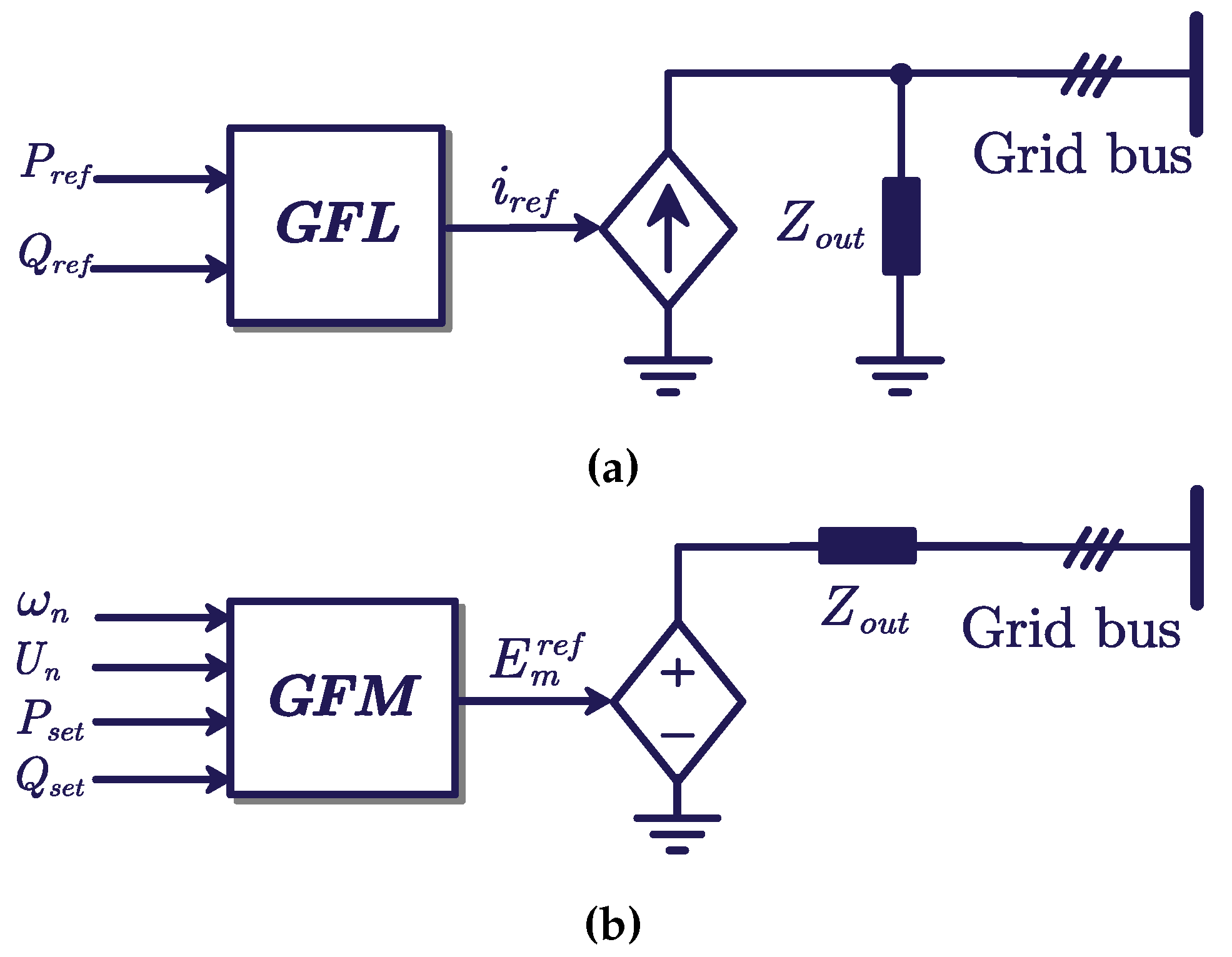
To address environmental issues such as climate change and carbon neutrality, electricity generation has been transitioned to renewable energy e.g. photovoltaic and wind. This change leads to the traditional grid acceleration, i.e., from being dominated by synchronous generators (SGs) to the grid characterized by a wide-scale application of renewable energy sources (RESs) and high penetration of power electronic converters. The control schemes of RES are typically categorized as grid-following (GFL) and grid-forming (GFM), with the GFL inverters being utilized worldwide nowadays [1]. As shown in
Figure 1a, the GFL inverters usually behave like a current source to inject power to the grid with high quality, where the output current is controlled by an inner current controller.
Compared with the traditional SG with a stiff internal voltage, the converters with GFL control have reduced the total inertia and damping of the entire power system, which manifests that the stability and robustness of the frequency and voltage are reduced [3]. Therefore, the inverter-based power system is susceptible to delayed responses or potential instability in the face of grid events, such as disturbances of the frequency and voltage. The European Network of Transmission System Operator for Electricity (ENTSO-E) reports both the decrease of traditional SGs and the increase of GFL inverters as the cause of the reduction in the stability of the power system [2]. Accordingly, extensive efforts have been dedicated to the advancement of GFM control, which can provide inertia and damping to the grid [4]. The inverter with a GFM control usually performs as a voltage source at the point of common coupling (PCC), as shown in
Figure 1b. Among various GFM control schemes, the virtual synchronous generator (VSG) is commonly applied to emulate the external characteristics of an SG, which can support the frequency and voltage of the power system in accordance with its droop characteristics (
and
) [5,6]. Benefited from the control flexibility of the grid-connected inverters, the damping and inertia of the VSG can be designed in response to specific requirements through the modification of parameters within the power control loop. Clearly, to design the GFM control, modeling the inverters is the foremost task.
There have been many publications focusing on the modeling and stability analysis of the individual grid-connected inverter. Modeling approaches of the grid-connected inverters are typically categorized into three methods: electromagnetic transient (EMT) modeling, impedance modeling and state space modeling. Based on the detailed model of every component within the entire power system, the EMT can replicate the grid disturbances and provide time-domain simulations for intuitive analysis of the complete system [8]. The EMT model retains the detailed structure of the system, even including dynamics of nonlinear elements, and thus provides an approximation closely reflecting actual variations. However, EMT modeling lacks theoretical support to unveil the mechanism behind the complex interaction and instability within the power system, and the EMT models for large-scale power systems demand significant computational burdens [7].
The impedance modeling approach focuses on the external characteristics of the grid-connected inverter by taking the inverter and the AC grid as two separated subsystems or two independent "black boxes". Considering the widely adopted current vector-control of the grid-connected inverter is based on a synchronous reference () frame, [9] studied the impacts of the phase-lock loop-(PLL) bandwidth in the frame using a 2×2 impedance matrix. The small-signal impedance model of the GFL inverter is derived to demonstrate its unique feature, i.e., the impedance being seen as a negative resistor. The magnitude of the negative resistor is determined by the rated power of the inverter, while the frequency range of this resistor is relevant to the bandwidth of the PLL [10]. Based on the impedance model, [11] analyzes the stability of the GFM inverter under different operating points, manifesting variations in stability margins within the low-frequency range. However, the decoupling control of the rotational frame cannot entirely eliminate the coupling effect between the d and q axis, namely the presence of the and channel impedance. If the impact of the coupling impedance is taken into consideration, the impedance of the inverter is a multiple-input multiple-output (MIMO) small-signal model, represented as a 2×2 matrix transfer function in the frequency domain. The stability margin of the MIMO system can be evaluated by the generalized Nyquist stability criterion [12] or the generalized MIMO Bode criterion [13]. However, it found in [14] that the generalized Nyquist stability criterion may lead to inaccurate stability analysis results under specific grid configuration. The Nyquist generalized stability criterion focuses on the external characteristic of the inverter output port, it is challenging to clarify the interaction mechanism between the inner control parameters and small-signal stability margin. Moreover, achieving the desired optimal parameter design also becomes particularly complex with the impedance model.
Utilizing the modern control theory, the state space model of the inverter is derived from the nonlinear differential equations with n state variables, which are linearized around the operating equilibrium point of the inverter. Based on the state space model, it is easy to calculate the eigenvalues and analyze the stability of the model. The analysis of eigenvalues can be adopted to identify the stability characteristic of the inverter system. The real part of the eigenvalues, , represents the damping of the whole model, which is equivalent to the small-signal stability margin, and is the stability criterion of the state space model. And, the imaginary part of the eigenvalues, , represents the oscillation characteristic of the inverter. Another advantage of the state space model lies in the utilization of the participation factors and sensitivity analysis methods. Participation factors facilitate the analysis of the mapping relationship between system state variables and small-signal stability margins [15], while sensitivity analysis enables the examination of the relationship between system control parameters and stability characteristics [16]. The eigenvalue analysis method is highly valuable due to its accurate results. Thus, this paper adopts the state space method for system modeling.
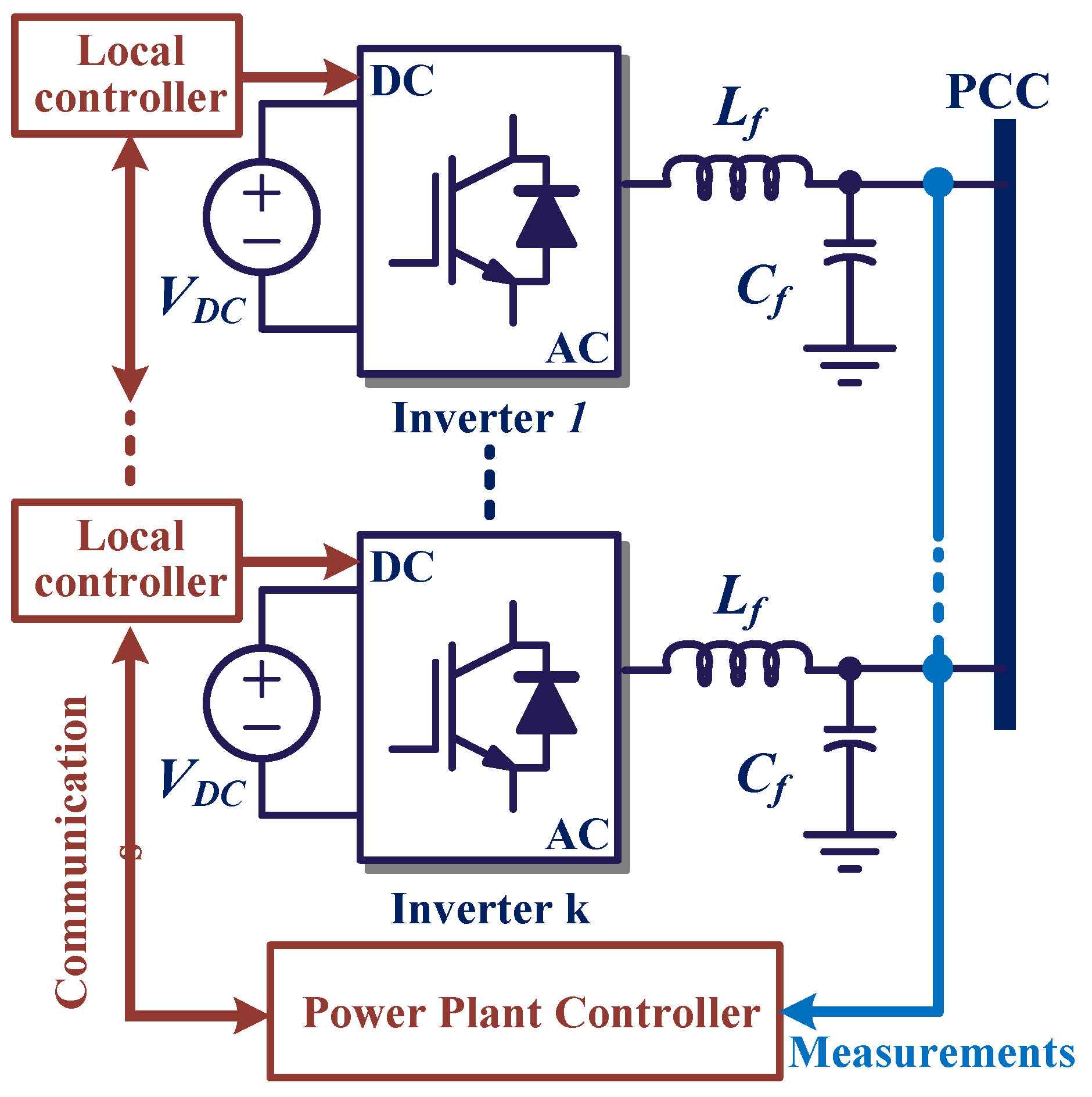
Most of the work above mainly focuses on the modeling and stability analysis of the individual inverter with a GFL or GFM control which is connected to an infinite AC bus [18]. However, in industrial applications, especially in RES power plants, the inverters are commonly connected in parallel to the PCC through line impedance, as depicted in
Figure 2. Therefore, to analyze the interactive coupling characteristics between parallel inverters, it is important to derive a detailed model of the entire inverter-based system. Many studies focus on the parallel inverters under the same control scheme, e.g., the GFL control [23,24], the droop control [20], the virtual oscillator control (VOC) [21] and the GFM control [22]. The neglect of parallel inverters under different controls declines the operation flexibility of the RES power plant [19]. Based on the impedance model, the work in [17] quantitatively assessed the impact of the increasing ratio of the GFM inverters on the oscillation frequency and damping, which reveals that the oscillation damping can be significantly improved with a higher penetration of GFM inverters. However, this study is based on the impedance model of the two-inverters system, which can not reflect the relation between the GFM inverter parameters and system stability margin directly. Therefore, it is still needed to derive the full-order state-space model of the hybrid inverter system, and analyze the effects of the GFM inverters on the stability margin of the system quantitatively seen from the perspectives of damping and frequency of the oscillatory modes.
With the above, this paper presents the small-signal model of parallel inverters, aiming to reveal the stability characteristics of multiple RES systems. The rest of this paper is organized as follows. Section II shows the control schemes of the GFL and GFM and the accurate full-order state space models of the individual inverters are formulated. Section III models the inverters-based system of GFL inverters in parallel, and then the hybrid inverter-based system with GFL and GFM controls is modeled in detail. Section IV studies a comparative case of the different characteristics of three parallel GFL inverter systems and the hybrid-parallel inverter system (two GFL inverters with a GFM inverter). Section V provides the conclusion remarks.
2. Control and Modeling of the Individual Inverter
The control of power inverters can generally be divided into GFL and GFM control strategies, with which the stability characteristics of the inverter exhibit significant differences. The GFL inverters are controlled as current sources to inject the desired current into the grid with high quality. To achieve the synchronization with the grid voltage, a PLL is utilized to trace the component of the PCC’s voltage vector . Considering the negative impedance of the PLL in a certain frequency range in the weak grid, the GFL inverter takes risks of instability when connected to a weak grid with a low short-circuit ratio (SCR) [25]. On the contrary, the inverter operating in the GFM mode demonstrates enhanced stability in the weak grid [11], and thus the GFM control is commonly applied to improve the stability of a low-inertia grid [26]. For the most commonly utilized GFM control, the VSG control synchronizes with the grid by the outer power loop. Given the extensive studies and application of the VSG control, this paper similarly employs it as a representative GFM control for modeling and analysis.
2.1. Grid-Following Control
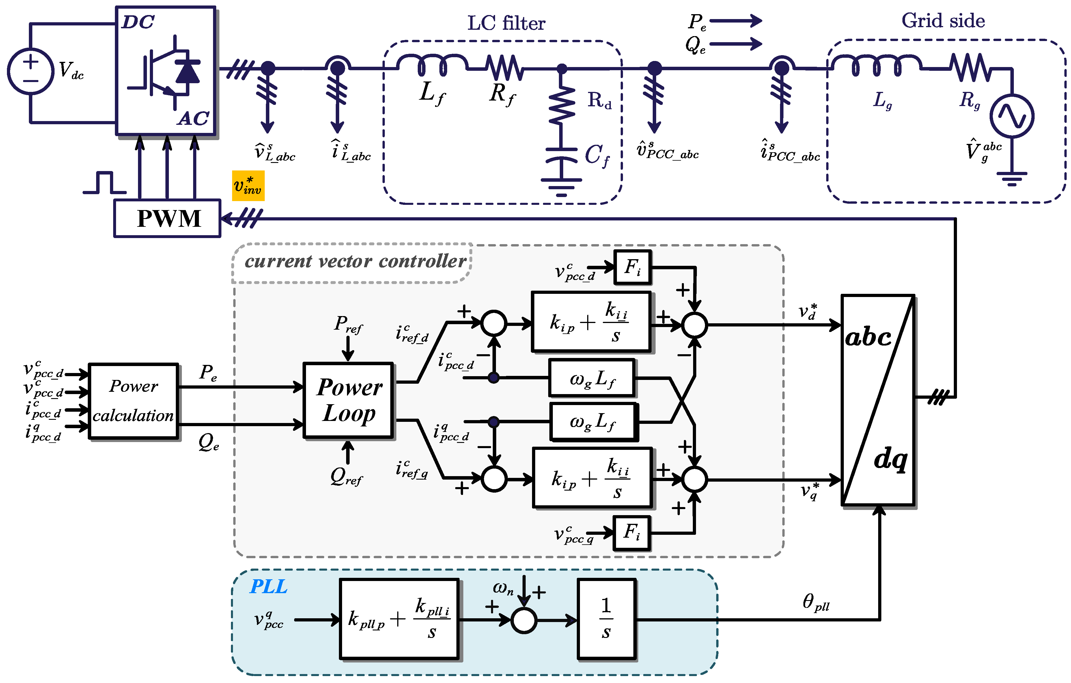
The inverters with GFL control are widely applied as the interface between the RESs and the power system, and this paper adopts the active-reactive power control (PQ control) as the outer power loop of the GFL control. The PLL unit generates the angle signal for the transformation from -axis to -axis by tracking the PCC’s voltage . The current vector controller adjusts the output currents according to current references generated by the power loop.
The control block diagram of a grid-connected inverter with the PQ GFL control is shown in
Figure 3, and the control is derived in
reference frame with the angle
.
is the DC-link voltage with a constant value by assuming the voltage is supplied by a stiff DC source;
and
are the filter inductor and resistance;
and
are the filter capacitor and its series damping resistor;
and
are the equivalent inductor and resistor of the grid, and
is the grid voltage. Moreover,
and
are the output voltages and currents of the inverter, while
and
are the voltages and currents of the PCC, respectively. By utilizing the Park transformation in Eq. (
1), the AC signals in the
-axis can be converted to
-signals:
where the subscripts
d and
q denote the d-axis and q-axis components of the corresponding variable
x respectively, and
is the phase angle. The parameters of the grid-connected inverter are shown in
Table 1.
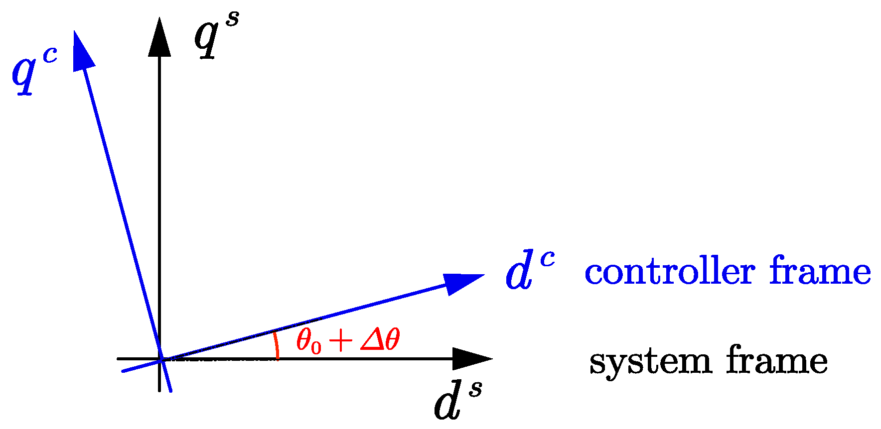
It is worth to mention that the reference frame is divided into system and controller frames, denoted by the superscript "
s" and "
c", respectively as depicted in
Figure 4, to assess the impact of transient synchronization dynamics [27]. The angle difference between the two frames is defined as
, which is equal to 0 in steady-state operation. Moreover, the small-signal perturbations of variables are denoted with
and the steady-state values of variables are represented with subscript "
0". In the rest of the paper, the variables are similarly named according to these rules. The system frame
is determined by the PCC voltage
, while the controller frame
is determined by the angle signal
from the PLL. To assess the small-signal stability of the inverter system, a small perturbation is added to the angle signal, and the transformation matrix
and
between the two frames are given in
Appendix A [28].
2.1.1. Phase-Locked Loop
The PLL enables the inverter to synchronize with the grid by orienting the voltage vector
to the
d-axis of the controller rotating reference frame accurately [25]. As shown in
Figure 3, the transfer function between
and
can be illustrated as:
where
and
are the proportional and integral parameters of the PLL respectively. Applying the transformation matrix
and
and the small-signal linearization method, Eq. (
2) can be rewritten in the time-domain as:
in which the
p denotes the differential operator, i.e.,
.
2.1.2. Power Control Loop
The output active power
and reactive power
of the inverter can be calculated as:
The power control loop generates the current references
and
for the inner current controller responding to the operating set-points
and
. The power control loop commonly consists of a proportional-integral (PI) controller with a slow dynamics, and the current references equations can be given as:
with
and
being the
components of the voltage
in the controller axis, and
and
being the current references in
-axis. In this paper, these are applied as the power loop of the GFL inverters. By adding a small signal perturbation to Eq. (
5), the following can be ontained:
where
Here the
and
are the set points of the inverter.
2.1.3. Current Controller Loop
The current controllers are applied to track the current references from the power loop with the PI controller, and the decoupling parts are added to mitigate the coupling effect of the
axis. The grid-voltage feedforward control is also applied to suppress the effect of the harmonics of the grid voltage and to enhance the synchronization stability with the voltage feedforward coefficients
[29]. The current controllers are given as:
where
is the rated angular velocity of the grid;
and
are the proportional and integral parameters of the current controller respectively;
and
are the modulating voltages.
Combing the matrices
and
, Eq. (
8) can be linearized as follows:
where
in which
and
are the outputs of the integral part of the current controllers;
and
represent the effect of the synchronization disturbance on the current loop.
2.1.4. Physical Circuit Model
Based the Kirchhoff’s law, the linearized equations of the physical circuit can be given as shown in Eq. (
11), which reflects the dynamics of the filter of the inverter and the impedance of the grid. This paper especially considers the existence of the damping resistance
, which exhibits a noticeable effect on the stability of the inverter in the high-frequency range.
where the
and
represent the disturbance of the grid;
and
denote the result of the modulating voltages
and
being effected by time-delay, and the approximation of the time delay will be discussed later.
2.1.5. Effect of Time Delay
The digital delay of the control and communication is considered as the factors resulting in instability of grid-connected inverters [30]. Time delays of the inverter will bring a phase lag to the control loop, which will decrease the phase margin and control bandwidth thus degrading the performance of the inverter [31]. The effect of time delay can be evaluated by the Padé approximation effectively, and the fitting frequency range and accuracy can be designed by the approximation orders
. This paper adopts a 3-order Padé approximation, which can be given as:
where
v represents the original signal, and
is the corresponding signal considering the time delay.
is the time delay and its value commonly considered to be 1.5 times the switching period, i.e.,
[31].
2.1.6. State-Space Model of the GFL Inverter
By considering Eqs. (
1), (
3), (
6), (
7), and (
9) to (
12), the state space model of the PQ-GFL inverter can be shown as:
where
is a
vector of state variables,
is a
matrix, and
is a
matrix.
is a
vector of input variables, given as:
in which the
and
are the disturbance of the set points.
The control parameters of a grid-connected GFL inverter are listed in
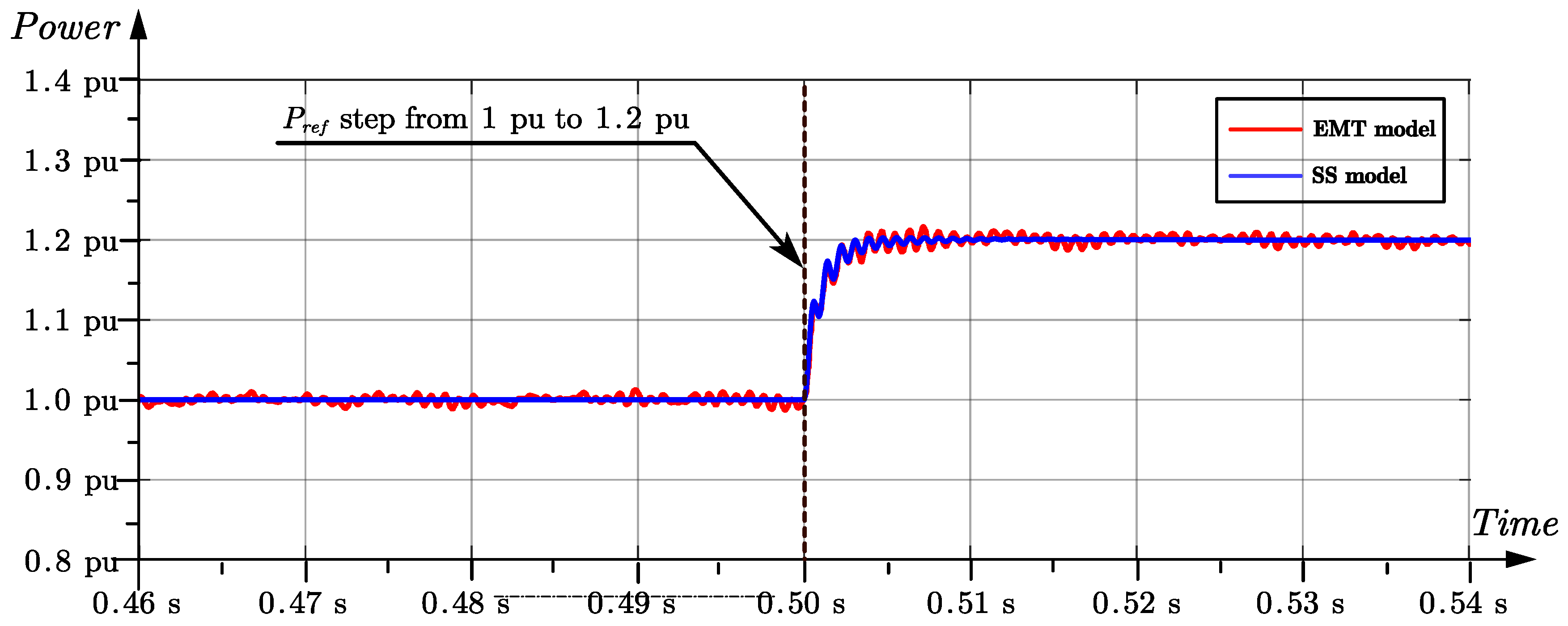
Table 2, and an EMT model in SIMULINK is compared to verify the accuracy of the state space model of the GFL inverter. As shown in
Figure 5, the active power reference
steps from 4
(1 pu) to 4.8
(1.2 pu) at 0.5 s. The blue line is the response from the state-space (SS) model while the red curve represents that from the EMT model. As depicted in
Figure 5, the active power response of the SS model matches well with the EMT model during transition, while presenting negligible ripples during steady-state operation.
Based on the SS model, the eigenvalue analysis can be applied to quantitatively assess the impact of system parameters on the stability. The traces of eigenvalues responding to the sweeps of the PLL parameters
and
, grid impedance
and
are depicted in
Figure 6. Here,
and
vary in the range [0, 35]
and [0, 3]
respectively, to represent various grid strength with different SCRs, and the SCR can be calculated as:
It can be observed in
Figure 6 (a) and (b) that the GFL inverter suffers from instability when the grid is relatively weak. With the decrease of the SCR, i.e. the increase of
and
, the locations of the eigenvalues are moving to the right half plane, meaning instability of the system. And,
has a more significant importance compared to
, considering the inductor will affect the phase of the PCC voltage
. According to the bandwidth
of the PLL defined in [25],
Figure 6 (c) and (d) show the eigenvalue changes with respect to
in the range of [1, 300] Hz under different grid strength. It can be observed that the GFL inverter has a smaller stability margin with a lower PLL bandwidth, especially when the grid is weak.
2.2. Grid-Forming Control
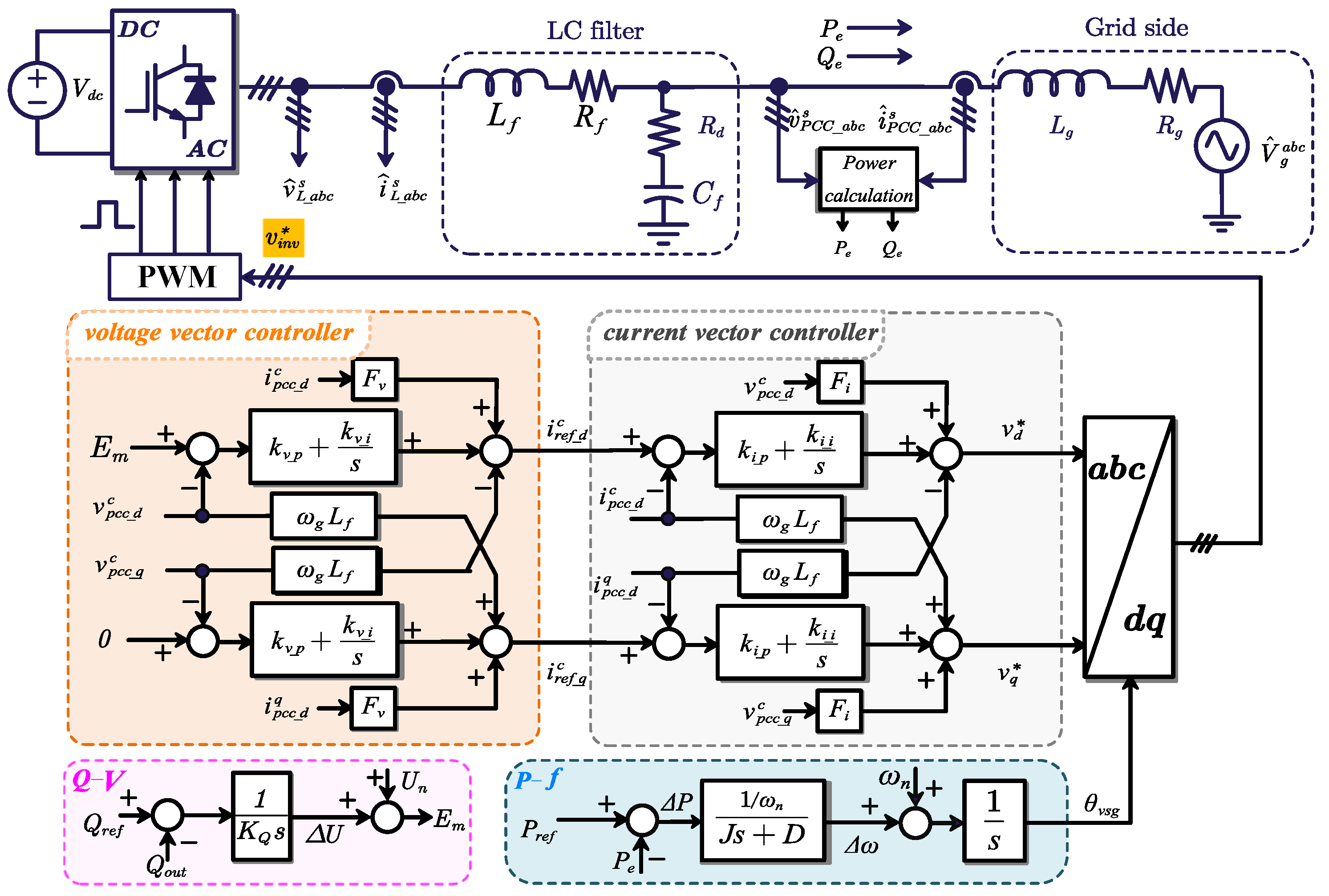
This paper adopts the commonly used VSG control as the GFM control, and the VSG control can provide inertia and voltage support to the grid by emulating the external characteristic of an SG. The control scheme of the VSG GFM inverter is depicted in
Figure 7. The main differences between the GFL and GFM control lie in the synchronization mechanism and the voltage controller. The GFM can achieve synchronization with the grid by the power synchronization loop (PSL) without detecting the phase of the grid voltage. The inertia characteristic of the PSL enables the GFM inverter to respond to frequency events with a transient power supply. The modeling of the current controller, the physical circuit and the time delay for the GFM inverter are the same as those for the GFL inverter.
2.2.1. Power Loop Control
The active power loop generates the control angle for the inverter by mimicking the mechanical part of an SG, while the reactive power loop determines the excitation electromotive force of the inverter following the stator voltage equation of an SG. The small signal equations of the power loop can be given as:
where
J is the virtual inertia coefficient;
is the damping coefficient;
is the integral coefficient of the reactive power loop. Without considering the virtual impedance, the output of the reactive power loop
is applied as the d-axis component of the voltage reference, while the q-axis component of the voltage reference is set to zero.
2.2.2. Voltage Control Loop
The voltage controller is applied to trace the voltage references from the power loop, and the output current feedforward control is applied with the gain of
. The equations of the voltage controller can be given as:
where
and
are the proportional and integral parameters of the voltage controller respectively.
Combing the matrices
and
, Eq. (
17) can be linearized as:
with
where
and
are the outputs of the integral part of the voltage controllers;
and
represent the effect of the synchronization disturbance on the voltage control loop,
d-axis and
q-axis respectively.
2.2.3. State-Space Model of the GFM Inverter
Similar to the GFL inverter, the state space model of the VSG-GFM inverter can be given as:
where
is a
vector of state variables,
is a
matrix, and
is a
matrix.
is a
vector of input variables that is the same as Eq. (
14).
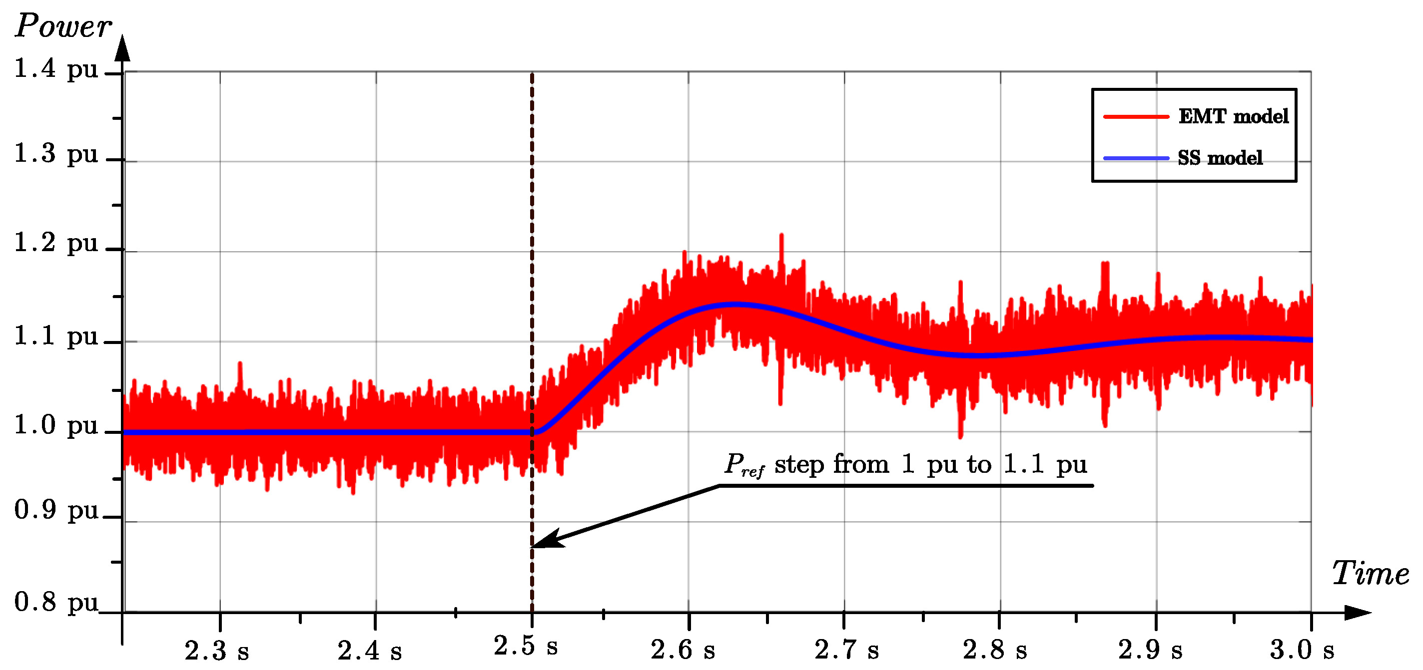
The control parameters of the 4-kW GFM Inverter are listed in
Table 3, and the comparison between EMT model and SS model is shown in
Figure 8, where the active power reference
steps from 4
(1 pu) to 4.4
(1.1) pu at 2.5 s. It can be observed that the blue line (SS model) matches well with the red line (EMT model), which shows the effectiveness of the SS model.
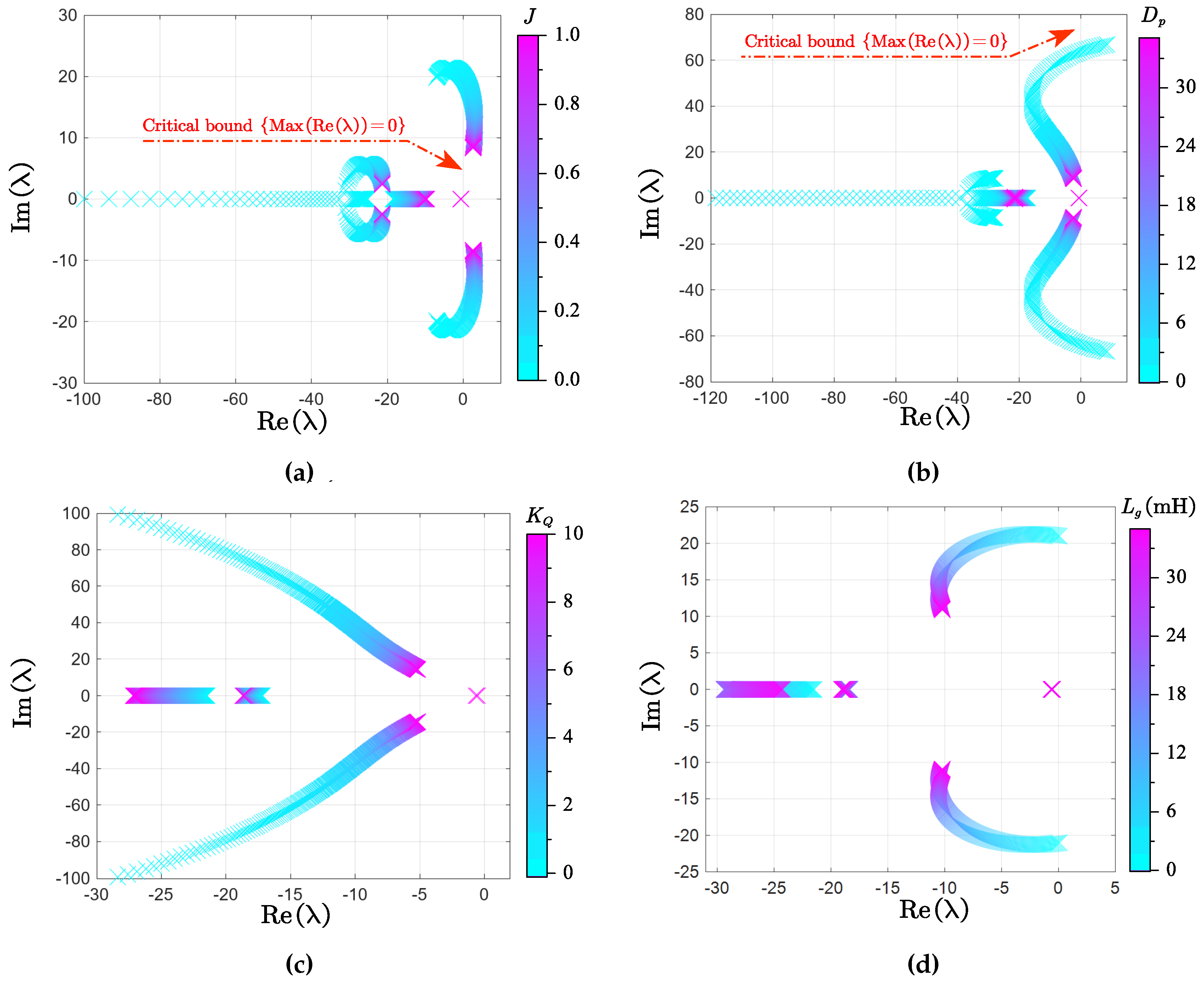
In
Figure 9, the traces of eigenvalues are presented to demonstrate the effect of the GFM parameters on the system’s stability. Here,
J and
of the active power loop sweep in the range [1e-3, 1] and [0.1, 10], respectively in
Figure 9 (a) and
Figure 9 (b), to exhibit the influence of different inertia and damping characteristics. Moreover,
of the reactive power loop varies in the range [0.1, 10] in
Figure 9 (c), while the grid impedance
changes from 0
to 35
in
Figure 9 (d). With the variation of active power parameters, the eigenvalue loci in
Figure 9 (a) shows that an unreasonable large value of system inertia
J produces a higher risk of instability, manifesting as a slow frequency oscillation. Similarly,
Figure 9 (b) shows the necessity for the GFM inverter to properly set the damping parameter
. Inadequate or excessive damping can lead to the dominant pole of the system locating quite near the imaginary axis, which even makes the inverter potentially unstable. Furthermore,
Figure 9 (c) shows the eigenvalues loci with the droop gain
of the reactive power loop, it is clear that the increase of
results in a narrower stable operation range of the GFM inverter, and even causes oscillation in the low-frequency.
2.3. Small-Signal Modeling of the Power Plant
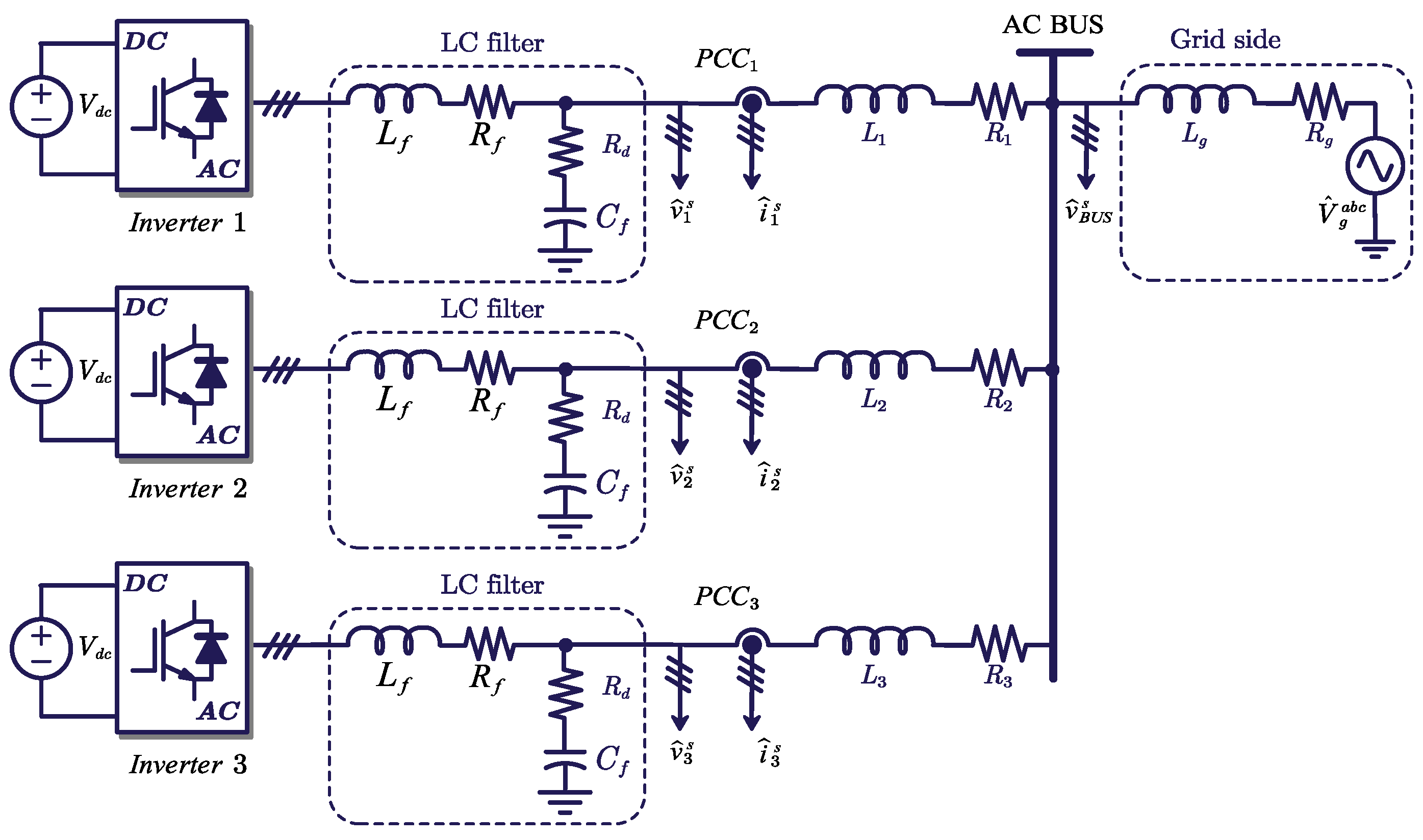
Without loss of generality, the configuration of the renewable power plant is simplified as depicted in
Figure 2, and an example with three inverters in parallel considering the transmission line dynamics is shown in
Figure 10.
The small signal model of the transmission line can be derived as follows:
where
and
are the state variables of the transmission line;
and
are the voltage of the connected bus.
3. Small-Signal Stability Analysis of Parallel Inverters
To quantitatively analyze the effect of the GFM inverter on the stability of the power plant, a case study involves parallel GFL inverters (three GFL inverters) and hybrid inverters (two GFL inverters and one GFM inverter) are built. For a more general discussion, the act power operation points of the inverters are set differently in the sequence of 3, 4, and 5 kW, and the other circuit parameters, GFL control parameters and GFM control parameters are listed in
Table 1,
Table 2,
Table 3 respectively.
With the above models, the small signal model of the power plant can be given as:
where
is the current of the transmission line;
and
are the system matrix and output vector, which can be easily derived according to the aforementioned equations.
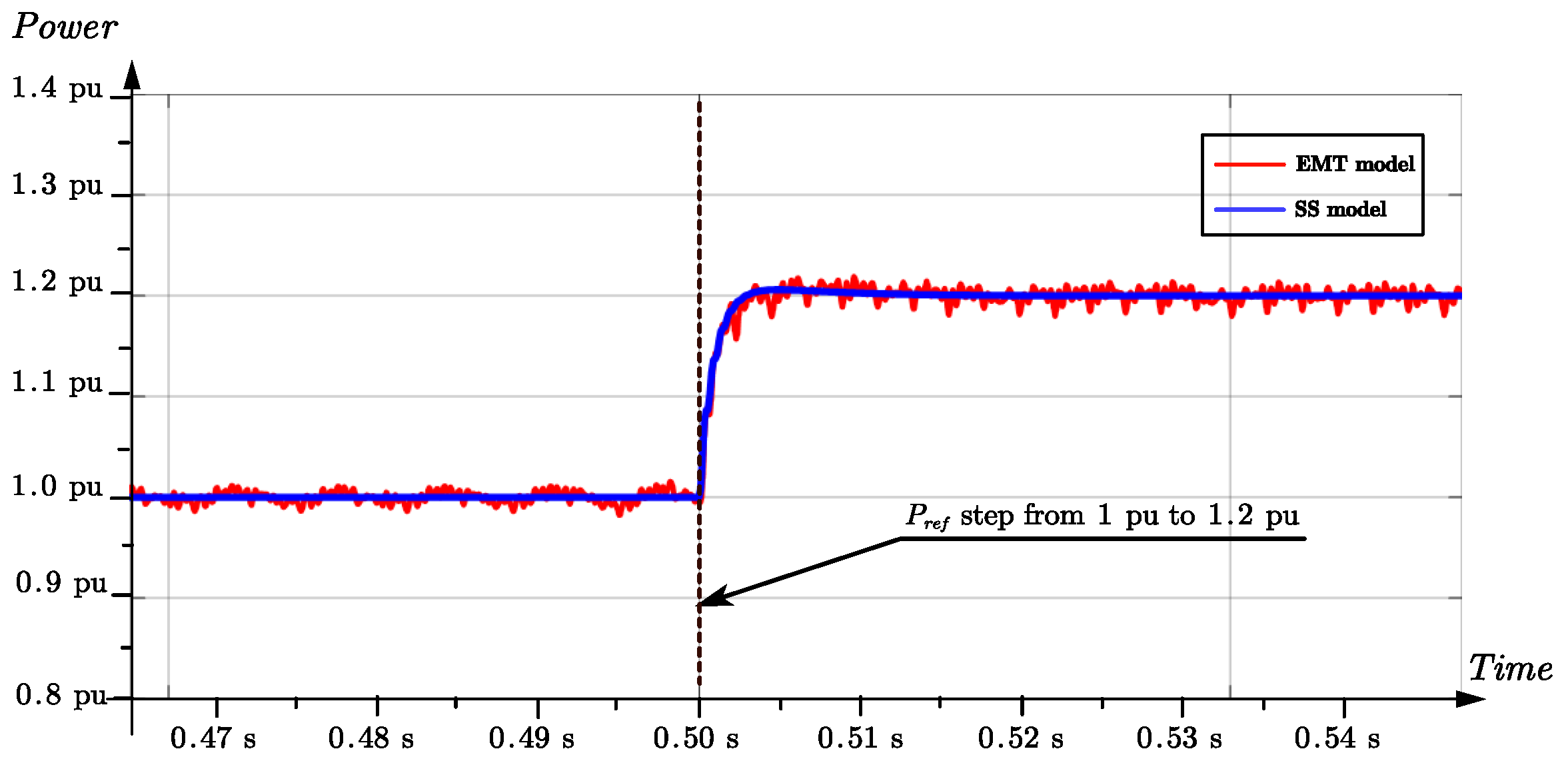
The SS model of three GFL inverters in parallel is established to represent a power plant with 100 % GFL inverters, and
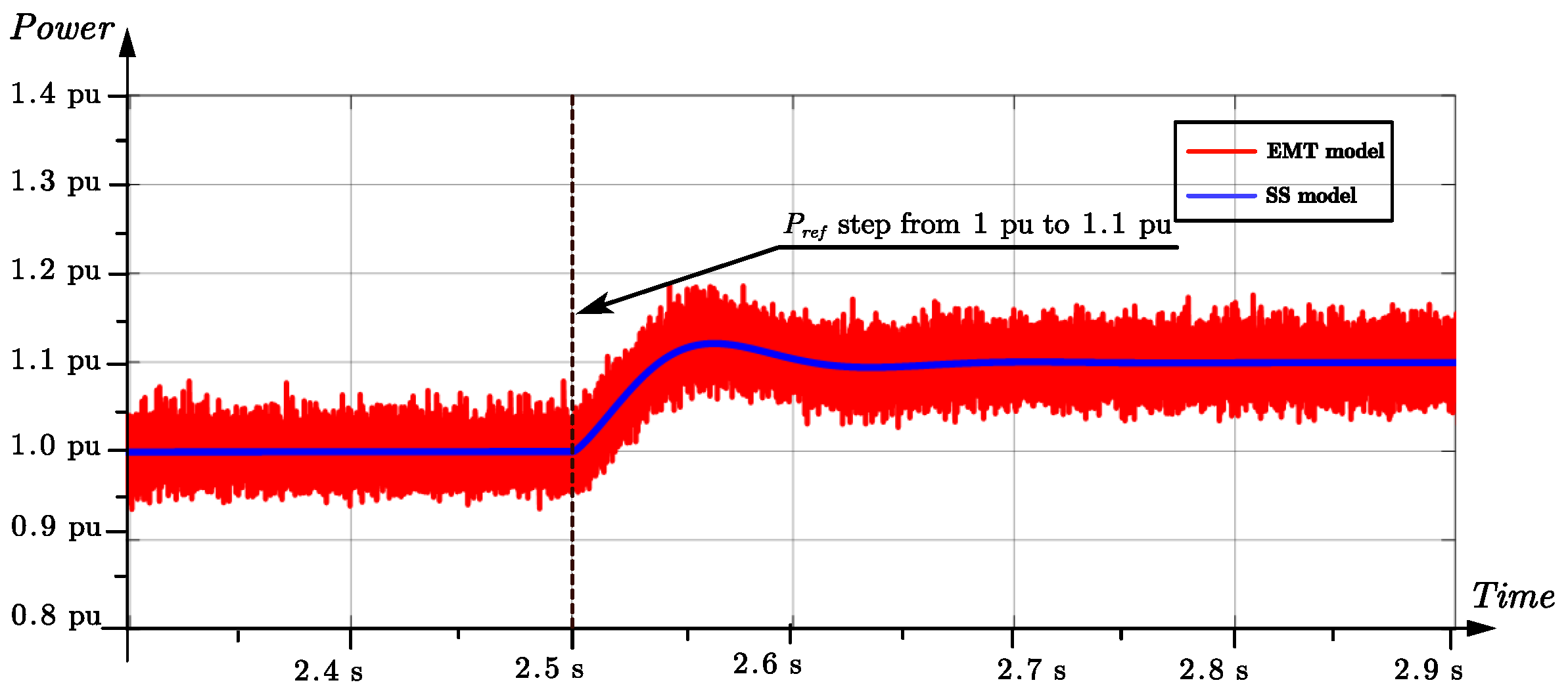
Figure 11 depicts the comparison results between the EMT model and SS model, which validate the accuracy of the SS model. Similarly, when one of the GFL inverter (Inverter 3 see
Figure 10) is controlled in GFM mode, the SS model is verified by the EMT model as shown in
Figure 12.
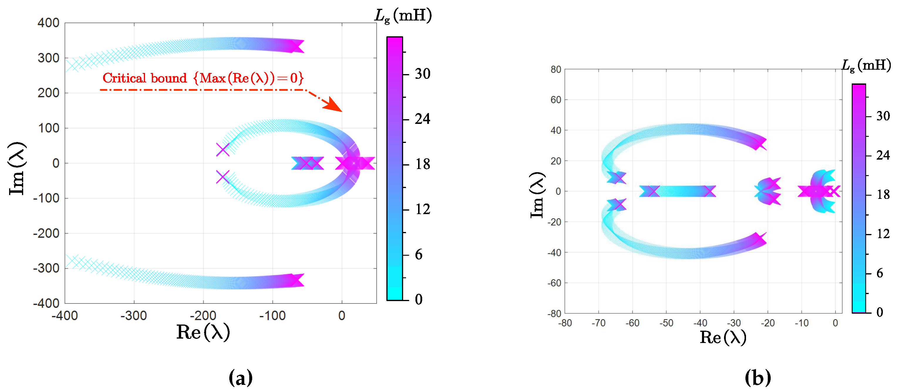
As shown in
Figure 13 (a), parts of the eigenvalues of the system will move to the left plane and the system can not maintain stability anymore, when the grid impedance
varies from 0
to 35
. That means the renewable power plant with 100% GFL inverters when the grid is relatively weak, which undermines the applicability of the power plant, especially in certain remote regions. This characteristic of the parallel GFL inverters is similar to the individual GFL inverter, as the synchronization with
is necessary for all GFL inverters. The eigenvalues loci of the hybrid inverter system is depicted in
Figure 13 (b), which shows the GFM inverter will enhance the system stability especially in weak grid conditions. The mechanism behind this can be explained as the GFM inverter participates in the establishment of the
, the equivalent grid is strengthened and improved. Consequently, the stability is enhanced.
4. Simulation Validation
In order to verify the stability analysis in
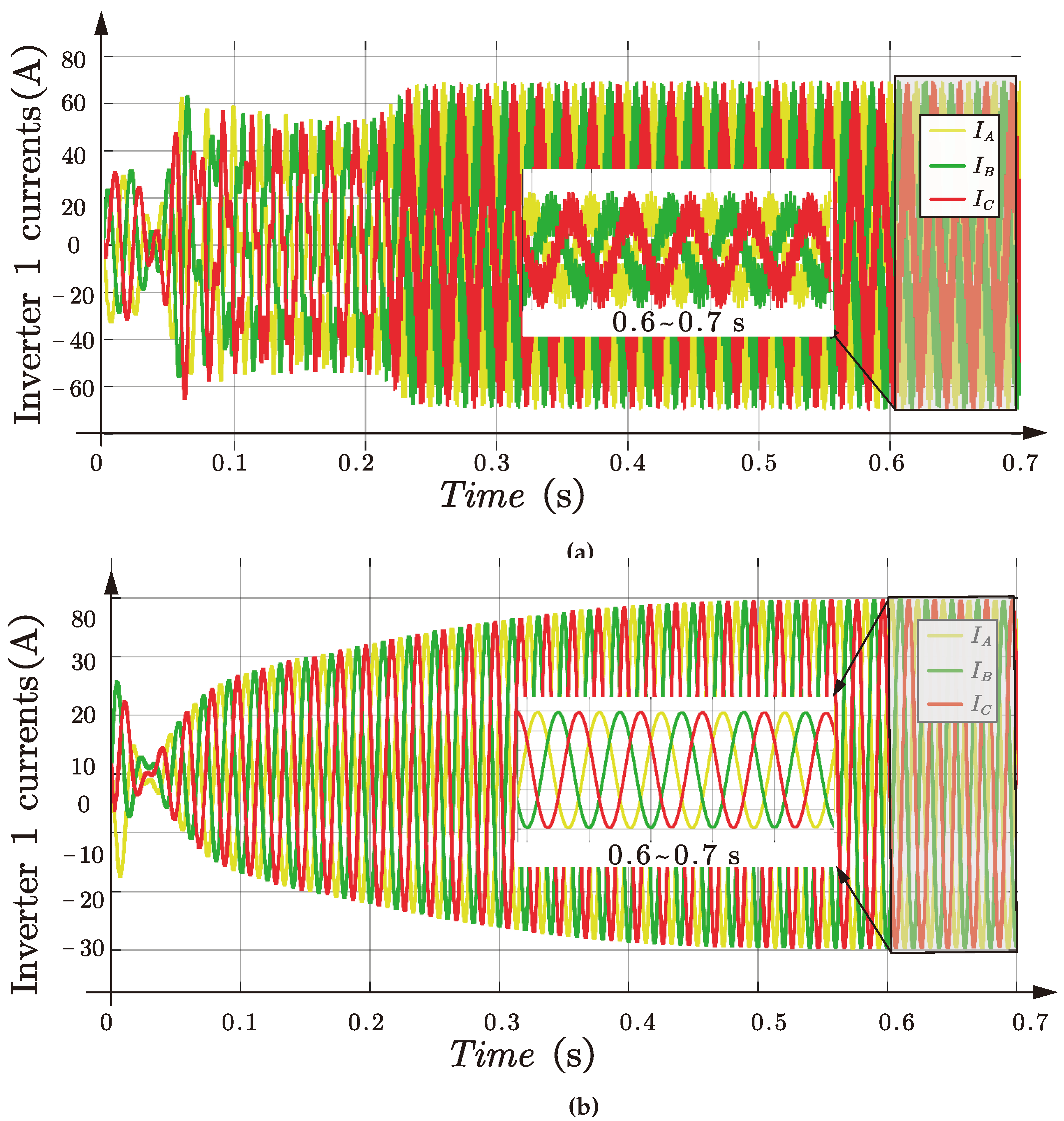
Section 3, the EMT model of the case study system is established in Matlab/Simulink. The simulation results are shown in
Figure 14. As depicted in
Figure 14, the parallel GFL inverters suffer from instability when the connected grid is relatively low with
= 20 mH, which will hazard the operation of the entire system. However, when the control of one inverter is changed from GFL to GFM mode, the hybrid inverter system keeps stable operation under the same grid condition, as the locations of the eigenvalues are improved and moved to the left-half plane beneficial from the application of the GFM, especially when considering the effect of grid conditions. Comparing the results of
Figure 14 (a) and (b), the efficacy of the stability analysis and the models are verified.
5. Conclusions
This paper focused on the small-signal modeling and analysis of the inverter with GFL and GFM control, and the effect of selected key parameters on the inverter’s stability was studied by analyzing the eigenvalues loci. First, the state-space model of the GFL inverter was derived step by step, and the impact of the transmission line and PLL parameters on the GFL inverter was considered. Then, the state-space model of the GFM inverter was established to study the impact of line impedance and power loop parameters. The accuracy of the small-signal models was assessed by the corresponding EMT simulations. Consequently, the state-space modeling of the renewable power plant was derived to quantitatively analyze the improvement of the GFM inverter on the stability margin of the power plant. The comparison of the stability analysis of a case consisting of three parallel GFL inverters and two GFL inverters with one GFM inverter, which demonstrates the stabilizing effect of the inertia and damping of the GFM inverter, and this was further verified by the time-domain simulations.
Author Contributions
These authors contributed equally to this work.
Funding
This work is supported by State Grid Corporation, China through the Project No.: 4000-202222070A-1-1-ZN.
Appendix A
Considering a vector
in the system frame
, the corresponding vector
in the controller frame
, the relationship of the two vectors considering small perturbation can be derived as:
And then, the 2-order small perturbation is neglected and the Taylor expansion is applied, and we can get:
Similarly, the transformation matrix
from the controller frame
to the system frame
can be derived.
References
- Rocabert, J.; Luna, A.; Blaabjerg, F.; Rodríguez, P. Control of Power Converters in AC Microgrids. IEEE Transactions on Power Electronics 2012, 27, 4734–4749. [Google Scholar] [CrossRef]
- Christensen, P.; Andersen, G.; Seidel, M.; Bolik, S.; Engelken, S.; Knueppel, T.; Krontiris, A.; Wuerflinger, K.; Bülo, T.; Jahn, J.; et al. High Penetration of Power Electronic Interfaced Power Sources and the Potential Contribution of Grid Forming Converters; 2020.
- Ulbig, A.; Borsche, T.S.; Andersson, G. Impact of Low Rotational Inertia on Power System Stability and Operation. IFAC Proceedings Volumes 2014, 47, 7290–7297. [Google Scholar] [CrossRef]
- Blaabjerg, F.; Yang, Y.; Kim, K.A.; Rodriguez, J. Power Electronics Technology for Large-Scale Renewable Energy Generation. Proceedings of the IEEE 2023, 111, 335–355. [Google Scholar] [CrossRef]
- Driesen, J.; Visscher, K. Virtual synchronous generators. In Proceedings of the 2008 IEEE Power and Energy Society General Meeting - Conversion and Delivery of Electrical Energy in the 21st Century; IEEE, 2008. [Google Scholar] [CrossRef]
- Beck, H.P.; Hesse, R. Virtual synchronous machine. In Proceedings of the 2007 9th International Conference on Electrical Power Quality and Utilisation; IEEE, 2007. [Google Scholar] [CrossRef]
- Horiuchi, S.; Sano, K.; Noda, T. An Inverter Model Simulating Accurate Harmonics with Low Computational Burden for Electromagnetic Transient Simulations. IEEE Transactions on Power Electronics 2021, 36, 5389–5397. [Google Scholar] [CrossRef]
- Sano, K.; Horiuchi, S.; Noda, T. Comparison and Selection of Grid-Tied Inverter Models for Accurate and Efficient EMT Simulations. IEEE Transactions on Power Electronics 2022, 37, 3462–3472. [Google Scholar] [CrossRef]
- Harnefors, L.; Bongiorno, M.; Lundberg, S. Input-Admittance Calculation and Shaping for Controlled Voltage-Source Converters. IEEE Transactions on Industrial Electronics 2007, 54, 3323–3334. [Google Scholar] [CrossRef]
- Wen, B.; Boroyevich, D.; Burgos, R.; Mattavelli, P.; Shen, Z. Analysis of D-Q Small-Signal Impedance of Grid-Tied Inverters. IEEE Transactions on Power Electronics 2016, 31, 675–687. [Google Scholar] [CrossRef]
- Xiao, Y.; Zhang, Z.; Luo, H.; Zhu, Y.; Yang, Y.; Molinas, M.; Xu, D. Stability Analysis of Grid-Forming Inverter Considering Different Operating Points. In Proceedings of the 2023 25th European Conference on Power Electronics and Applications (EPE’23 ECCE Europe); IEEE, 2023. [Google Scholar] [CrossRef]
- Wen, B.; Boroyevich, D.; Burgos, R.; Mattavelli, P.; Shen, Z. Inverse Nyquist Stability Criterion for Grid-Tied Inverters. IEEE Transactions on Power Electronics 2017, 32, 1548–1556. [Google Scholar] [CrossRef]
- Samanes, J.; Urtasun, A.; Barrios, E.L.; Lumbreras, D.; Lopez, J.; Gubia, E.; Sanchis, P. Control Design and Stability Analysis of Power Converters: The MIMO Generalized Bode Criterion. IEEE Journal of Emerging and Selected Topics in Power Electronics 2020, 8, 1880–1893. [Google Scholar] [CrossRef]
- Qiao, L.; Xue, Y.; Kong, L.; Wang, F. A Potential Issue of Using the MIMO Nyquist Criterion in Impedance-Based Stability Analysis. IEEE Open Journal of Power Electronics 2022, 3, 899–904. [Google Scholar] [CrossRef]
- Wang, Y.; Wang, X.; Blaabjerg, F.; Chen, Z. Harmonic Instability Assessment Using State-Space Modeling and Participation Analysis in Inverter-Fed Power Systems. IEEE Transactions on Industrial Electronics 2017, 64, 806–816. [Google Scholar] [CrossRef]
- Yang, L.; Xu, Z.; Østergaard, J.; Dong, Z.Y.; Wong, K.P.; Ma, X. Oscillatory Stability and Eigenvalue Sensitivity Analysis of A DFIG Wind Turbine System. IEEE Transactions on Energy Conversion 2011, 26, 328–339. [Google Scholar] [CrossRef]
- LIU Pengyin1, XIE Xiaorong1*, L.Y.Y.S.S.P.D.X.; Ningning1, M. Mechanism and Characteristics of Grid-forming Control for Improving Sub/Super Synchronous Oscillation Stability of Grid-following-based Grid-connected Converter. Power System Technology.
- Zhang, Z.; Zhu, Y.; Yang, Y.; Peng, Y.; Duan, Q.; Zhu, Z. Operational Flexibility of Grid-Connected Power Converters for Renewable Energy Integration. In Proceedings of the 2023 IEEE Transportation Electrification Conference and Expo, Asia-Pacific (ITEC Asia-Pacific); 2023; pp. 1–3. [Google Scholar] [CrossRef]
- Zhang, Z.; Yang, Y. Control Flexibility of Power Converters for Seamless Transition between Grid-Following and Grid-Forming Modes. In Proceedings of the 2023 IEEE 2nd International Power Electronics and Application Symposium (PEAS); 2023; pp. 1015–1020. [Google Scholar] [CrossRef]
- Pogaku, N.; Prodanovic, M.; Green, T.C. Modeling, Analysis and Testing of Autonomous Operation of an Inverter-Based Microgrid. IEEE Transactions on Power Electronics 2007, 22, 613–625. [Google Scholar] [CrossRef]
- Khan, M.M.S.; Lin, Y.; Johnson, B.; Purba, V.; Sinha, M.; Dhople, S. A Reduced-order Aggregated Model for Parallel Inverter Systems with Virtual Oscillator Control. In Proceedings of the 2018 IEEE 19th Workshop on Control and Modeling for Power Electronics (COMPEL); IEEE, 2018. [Google Scholar] [CrossRef]
- Zhang, B.; Yan, X.; Li, D.; Zhang, X.; Han, J.; Xiao, X. Stable Operation and Small-Signal Analysis of Multiple Parallel DG Inverters Based on a Virtual Synchronous Generator Scheme. Energies 2018, 11, 203. [Google Scholar] [CrossRef]
- Zhou, Y.; Xin, H.; Wu, D.; Liu, F.; Li, Z.; Wang, G.; Yuan, H.; Ju, P. Small-Signal Stability Assessment of Heterogeneous Grid-Following Converter Power Systems Based on Grid Strength Analysis. IEEE Transactions on Power Systems 2023, 38, 2566–2579. [Google Scholar] [CrossRef]
- Schramm Dall’Asta, M.; Brunelli Lazzarin, T. Small-Signal Modeling and Stability Analysis of a Grid-Following Inverter with Inertia Emulation. Energies 2023, 16, 5894. [Google Scholar] [CrossRef]
- Song, Y.; Sahoo, S.; Yang, Y.; Blaabjerg, F. Probabilistic Risk Evaluation of Microgrids Considering Stability and Reliability. IEEE Transactions on Power Electronics 2023, 38, 10302–10312. [Google Scholar] [CrossRef]
- Markovic, U.; Stanojev, O.; Aristidou, P.; Vrettos, E.; Callaway, D.; Hug, G. Understanding Small-Signal Stability of Low-Inertia Systems. IEEE Transactions on Power Systems 2021, 36, 3997–4017. [Google Scholar] [CrossRef]
- Harnefors, L.; Bongiorno, M.; Lundberg, S. Input-Admittance Calculation and Shaping for Controlled Voltage-Source Converters. IEEE Transactions on Industrial Electronics 2007, 54, 3323–3334. [Google Scholar] [CrossRef]
- Zhao, L.; Jin, Z.; Wang, X. Analysis and Damping of Low-Frequency Oscillation for DC-Link Voltage-Synchronized VSCs. IEEE Transactions on Power Electronics 2023, 38, 8177–8189. [Google Scholar] [CrossRef]
- Wang, X.; Ruan, X.; Liu, S.; Tse, C.K. Full Feedforward of Grid Voltage for Grid-Connected Inverter With LCL Filter to Suppress Current Distortion Due to Grid Voltage Harmonics. IEEE Transactions on Power Electronics 2010, 25, 3119–3127. [Google Scholar] [CrossRef]
- Tu, Y.; Liu, J.; Liu, Z.; Xue, D.; Cheng, L. Impedance-Based Analysis of Digital Control Delay in Grid-Tied Voltage Source Inverters. IEEE Transactions on Power Electronics 2020, 35, 11666–11681. [Google Scholar] [CrossRef]
- de Bosio, F.; de Souza Ribeiro, L.A.; Freijedo, F.D.; Pastorelli, M.; Guerrero, J.M. Effect of State Feedback Coupling and System Delays on the Transient Performance of Stand-Alone VSI With LC Output Filter. IEEE Transactions on Industrial Electronics 2016, 63, 4909–4918. [Google Scholar] [CrossRef]
Figure 1.
Equivalent circuits of grid-connected inverters: (a) GFL inverter and (b) GFM inverter.
Figure 1.
Equivalent circuits of grid-connected inverters: (a) GFL inverter and (b) GFM inverter.
Figure 2.
Configuration of RES power plant with k inverters.
Figure 2.
Configuration of RES power plant with k inverters.
Figure 3.
A grid-connected inverter system with the PQ GFL control.
Figure 3.
A grid-connected inverter system with the PQ GFL control.
Figure 4.
System frame and controller frame .
Figure 4.
System frame and controller frame .
Figure 5.
Comparison of EMT simulations and State-space (SS) GFL model in response to the power reference step from 1.0 pu to 1.1 pu at 0.5 s.
Figure 5.
Comparison of EMT simulations and State-space (SS) GFL model in response to the power reference step from 1.0 pu to 1.1 pu at 0.5 s.
Figure 6.
Traces of eigenvalues of the GFL inverter. (a) varies in [0, 35] , (b) varies in [0, 3] , (c) varies in [0, 300] Hz with SCR = 1.65, and (d) varies in [0, 300] Hz with SCR = 5.78.
Figure 6.
Traces of eigenvalues of the GFL inverter. (a) varies in [0, 35] , (b) varies in [0, 3] , (c) varies in [0, 300] Hz with SCR = 1.65, and (d) varies in [0, 300] Hz with SCR = 5.78.
Figure 7.
A grid-connected inverter system with the VSG control.
Figure 7.
A grid-connected inverter system with the VSG control.
Figure 8.
Comparison of EMT simulations and state-space (SS) GFM model in response to power reference step from 1.0 pu to 1.2 pu at 2.5 s.
Figure 8.
Comparison of EMT simulations and state-space (SS) GFM model in response to power reference step from 1.0 pu to 1.2 pu at 2.5 s.
Figure 9.
Traces of eigenvalues of the GFM inverter. (a) J varies in [0, 1] with = 1.7, (b) varies in [0, 10] with J = 0.005, (c) varies in [0, 10], and (d) varies in [0, 35] .
Figure 9.
Traces of eigenvalues of the GFM inverter. (a) J varies in [0, 1] with = 1.7, (b) varies in [0, 10] with J = 0.005, (c) varies in [0, 10], and (d) varies in [0, 35] .
Figure 10.
An example of the configuration of three inverters in parallel.
Figure 10.
An example of the configuration of three inverters in parallel.
Figure 11.
Comparison of EMT simulations and state-space (SS) model of parallel GFL inverters in response to the power reference step from 1.0 pu to 1.2 pu of Inverter 3 (see
Figure 10) at 0.5 s.
Figure 11.
Comparison of EMT simulations and state-space (SS) model of parallel GFL inverters in response to the power reference step from 1.0 pu to 1.2 pu of Inverter 3 (see
Figure 10) at 0.5 s.
Figure 12.
Comparison of EMT simulations and state-space (SS) model of hybrid parallel inverters in response to the power reference step from 1.0 pu to 1.1 pu of Inverter 3 (see
Figure 10) at 2.5 s.
Figure 12.
Comparison of EMT simulations and state-space (SS) model of hybrid parallel inverters in response to the power reference step from 1.0 pu to 1.1 pu of Inverter 3 (see
Figure 10) at 2.5 s.
Figure 13.
Traces of eigenvalues of three inverters in parallel: (a) varies in [0, 35] for three GFL inverters, and (b) varies in [0, 35] for two GFL inverters and one GFM inverter.
Figure 13.
Traces of eigenvalues of three inverters in parallel: (a) varies in [0, 35] for three GFL inverters, and (b) varies in [0, 35] for two GFL inverters and one GFM inverter.
Figure 14.
Output three phases currents of three inverters in parallel. (a) of three GFL inverters, and (b) of two GFL inverters and one GFM inverter.
Figure 14.
Output three phases currents of three inverters in parallel. (a) of three GFL inverters, and (b) of two GFL inverters and one GFM inverter.
Table 1.
Circuit Parameters of A 4-kW Grid-connected Inverter.
Table 1.
Circuit Parameters of A 4-kW Grid-connected Inverter.
| Circuit Parameters |
Symbol |
Value |
| DC-side
voltage |
|
700 V
|
| AC-side
voltage (RMS) |
|
220 V
|
| Rated grid frequency |
|
50
|
| Switching
frequency |
|
20
|
| Rated active
power |
|
10
|
| Rated reactive
power |
|
0
|
| Grid
inductance |
|
2
|
| Grid resistance |
|
0.2
|
| Filter inductance |
|
5 mH |
| Filter resistance |
|
0.5
|
| Filter capacitance |
|
500
|
| Damping resistance |
|
3
|
| Sampling time |
|
50
|
Table 2.
Control Parameters of the 4-kW GFL Inverter.
Table 2.
Control Parameters of the 4-kW GFL Inverter.
| GFL Control Parameters |
Symbol |
Value |
| Proportional coefficient of the PLL |
|
|
| Integral coefficient of the PLL |
|
|
| Proportional coefficient of the current controller |
|
|
| Integral coefficient of the current controller |
|
800 |
| Voltage-forward coefficient |
|
0 |
| Active power reference |
|
4 kW |
| Reactive power reference |
|
0 Var |
| Delay time |
|
s |
| Delay orders |
|
3 |
Table 3.
Control Parameters of the 4-kW GFM Inverter.
Table 3.
Control Parameters of the 4-kW GFM Inverter.
| GFM Control Parameters |
Symbol |
Value |
| Inertia coefficient |
J |
|
| Damping coefficient |
|
|
| Integral coefficient of the Q-V loop |
|
|
| Proportional coefficient of the voltage controller |
|
|
| Integral coefficient of the voltage controller |
|
|
| Proportional coefficient of the current controller |
|
28 |
| Integral coefficients of the current controller |
|
600 |
| Current-forward coefficient |
|
0 |
| Voltage-forward coefficient |
|
0 |
| Active power reference |
|
4 kW |
| Reactive power reference |
|
0 Var |
| Delay time |
|
s |
| Delay orders |
|
3 |
|
Disclaimer/Publisher’s Note: The statements, opinions and data contained in all publications are solely those of the individual author(s) and contributor(s) and not of MDPI and/or the editor(s). MDPI and/or the editor(s) disclaim responsibility for any injury to people or property resulting from any ideas, methods, instructions or products referred to in the content. |
© 2024 by the authors. Licensee MDPI, Basel, Switzerland. This article is an open access article distributed under the terms and conditions of the Creative Commons Attribution (CC BY) license (http://creativecommons.org/licenses/by/4.0/).
