Introduction
Flexible pressure sensors have been increasingly used in wearable devices, electronic skins and personal health monitoring [
1,
2,
3], which are capable of converting pressure into corresponding electrical signals. Among the four types of pressure sensors (piezoresistive, capacitive, piezoelectric and triboelectric [
4,
5,
6,
7]), piezoresistive pressure sensors arouse tremendous attention with its simple structure, feasible fabrication process and low cost. With the rapid development of flexible piezoresistive pressure sensors, the structure design and manufacturing has been mainly focused [
8]. Owing to the advantages of lightweight, large specific surface area and high porosity, 3D porous structure has become an effective strategy to achieve promising piezoresistive performance which has been applied in widespread fields [
9]. It has been demonstrated that 3D TPMS structure used to design the structure of the piezoresistive pressure sensors with local area minimization is able to reduce surface tension as well as surface energy and lower residual stress [
10]. Several 3D piezoresistive sensors have been realized by TPMS structure. For example, Peng et al. [
11] prepared a flexible sensor with TPMS structure which exhibited light weight, air permeability and high stretchability. In addition, the sensors with TPMS structure exhibit higher resilience than those with bulk structure.
Imanian et al. [
12]
engineered soft piezoresistive wearable conductors with TPMS-based architectures and evaluated
the effects of pore shape on piezoresistivity in four different TPMS structures (i.e. Primitive, Diamond, Gyroid, and I-WP). Davoodi et al. [
13] fabricated durable and flexible 3D conductive sensors with interconnected TPMS structures, and found that different structural cell types resulted in gauge factors ranging from 1 and 10. Ronca et al. [
14] investigated the electrical and thermal conductivity, mechanical strength of the thermoplastic polyurethane/graphene porous structure designed by TMPS equations corresponding to Schwarz , Diamond , and Gyroid unit cells. TPMS structures have been used as synthetic bone grafts, confirming high permeability and great potential for bone repairing [
15,
16].
Different additive manufacturing technologies have been used for 3D piezoresistive pressure sensors. Wei et al. [
17] fabricated 3D multifunctional polyurethane/carbon black sensors by direct ink writing using a 3D printer equipped with a 400 um nozzle. Kim et al. [
18] fabricated 3D multiaxial force sensor using fused deposition modeling(FDM) 3D printing of carbon nanotube nanocomposite. However, sensitive soft materials such as polydimethylsiloxane (PDMS) are extremely difficult to be 3D printed, meantime the surface of parts fabricated by nozzle-based printing techniques is usually rough. As a result, it is expected to take advantage of 3D printing to build a sacrificial mold into which the conductive polymer is poured, and then the mold can be disposed of in various ways. Alsharari et al. [
19] presented a method to fabricate soft compressible multilayer pressure sensors via sacrificial FDM 3D printing, which demonstrate linear and reproducible response with wide range sensitivity. Sixt et al. [
20] fabricated
flexible piezoresistive pressure sensors by dissolving acrylonitrile butadiene styrene
sacrificial mold fabricated by FDM in acetone. Peng et al. [
21] fabricated a porous flexible strain sensor by casting polyurethane/carbon nanotube composites into the DLP-printed sacrificial mold, which showed high stretchability and excellent recoverability. In general, conductive polymer composites are usually heated at low temperature for a long time by the external heat source during the fabrication process. The conductive fillers are usually dispersed into the elastomer matrix to make the sensors highly conductive. With
the electrical conductivity
and the Joule heating effect
of fillers, the self-resistance electric heating is of great interest, which has shorter preparation time,
lower energy consumption and higher mold dimensional stability compared with using the external heat source [
22,
23,
24].
However, little research has been reported on pressure sensors with porous TPMS structure generated using the self-resistance electric heating with a 3D printed sacrificial mold. The introduction of new pore geometries by 3D printing, as well as the self-resistance electric heating are critical to the mechanical and piezoresistive properties of the sensors. This paper aims to study porous piezoresistive sensors composed of PDMS and multi-walled carbon nanotubes (MWCNTs) based on 3D TPMS structureswith the self-resistance electric heating. Three different electric fields were applied to the conductive composites during the heating process. The compressive and piezoresistive properties of the porous composites based on different TPMS types such as Diamond, Gyroid, and I-WP unit cells were studied. By filling the research gap and introducing new approaches such as TPMS-based pore geometries and self-resistance electric heating, this study has the potential to enhance the design and fabrication of next-generation pressure sensors for various applications including wearable devices, electronic skins, and health monitoring systems.
2. Methods and Materials
2.1. Design of Sacrificial Models Based on TPMS Structures
To the design of 3D porous structures, a mathematical approach has been used, starting from triply periodic minimal surface (TPMS) equations. Furthermore, TPMS are minimal surfaces periodic in three independent directions, extend infinitely, and in the absence of self-intersections, divide the space into two labyrinths. TPMS can be obtained by trigonometric functions with three-dimensional architectures. Trigonometric functions that described the architectures of Diamond (D), Gyroid (G) and I-WP(I) are as follows:
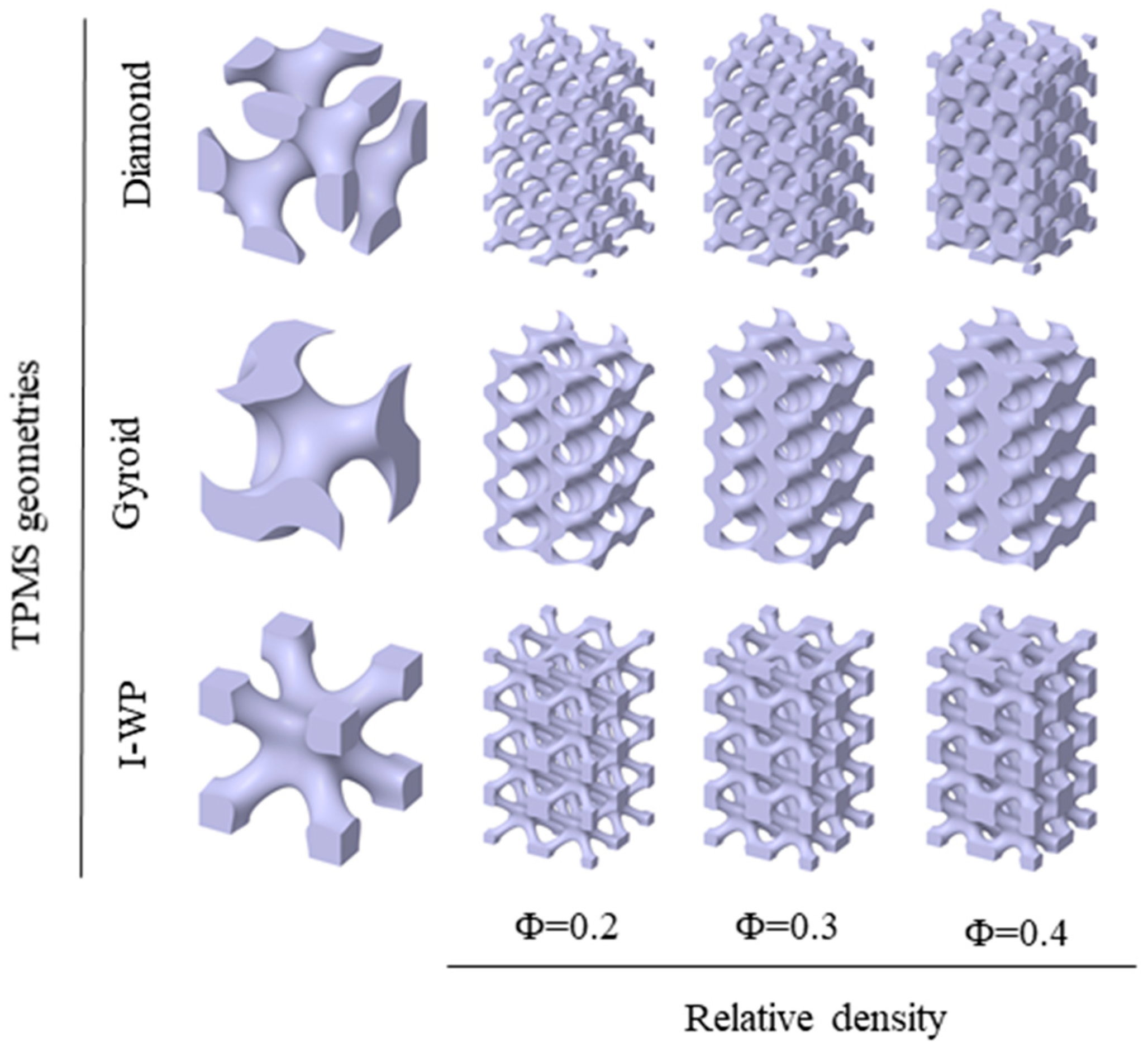
where, X=2απx, Y=2βπy, Z=2γπz. The left-hand side of the equations controls the iso-surface shape and the parameter C on the right-hand side represents the iso-value at which the surface is plotted. Here, the coefficients α, β, and γ are used to control the dimensions of the unit cell along the x, y, and z directions. The parameter C is the offset which controls the porosity of the structures. while the derived structure is uniform with the constant C, the derived structure is gradient with the field variable C. In this study, the minimal surface generation software MSLattice was used to generate the TPMS structure with solid networks. and the TPMS structure, namely Diamond(D), Gyroid(G) and I-WP(I) with a single unit cell as shown in
Figure 1. Relative density is one of the most important properties for a lattice structure. Three relative density values (0.2, 0.3 and 0.4) were set for each geometry in order to study the effect of porosity on mechanical behavior and electrical conductivity. The original CAD models consist of cuboidal porous geometries with a height of 20 mm and side length of 10 mm where 4×2×2 unit cells are repeated along with a 5 mm cubic unit cell, as shown in
Figure 1. The relative densities of the remaining conductive structures after dissolution of the sacrificial samples are 0.8, 0.7 and 0.6, respectively. In the following, Diamond, Gyroid and I-WP based porous structures are labeled as DX, GX and IX, respectively, where D, G or I represents the geometry and X represents the density value. For example, G0.8 represents a Gyroid-based architecture with a density of 0.8.
2.2. Preparation of Conductive Porous Structures
Acryloyl morpholine (ACMO) as the monomer was obtained from KJ Chemicals Co. Japan. Diphenyl (acyl) phosphine oxide (TPO) as the photoinitiator and Sudan Orange G as the light absorber were purchased from Aladdin Co. Ltd., China. 1-decanethiol (purity:96%) as the free radical chain transfer agent and polydimethylsiloxane (PDMS) and its curing agent were obtained from Sigma Aldrich, Germany. Multi-walled carbon nanotube (MWCNT) (diameter 9.5 nm, length 1.5 μm ,purity>90%) was purchased from Shanghai Xiyan Co. Ltd., China. All materials were directly used without further purification.
The water-soluble sacrificial samples are fabricated using liquid crystal display (LCD) 3D printer (Creality Co. Ltd., China) The main components of the water-soluble sacrificial resin are ACMO, TPO, 1-decanethiol and Sudan Orange G. To prepare a sacrificial resin solution, 1 wt.% TPO, 0.5 wt.% 1-decanethiol, and 0.025 wt.% Sudan Orange G were added to the monomer ACMO solution, stirred at 500 rpm for 15 min to form a uniform mixture, and then placed in the hot water at 70 °C for 15 min until the resin was homogeneous. After designing the structure of removal sacrificial samples, the commercial software Chitubox was used to slice and define the printing parameters with the wavelength of 405 nm, the exposure time of 3.5 s for each layer and 4 s for the bottom and a 500 μm layer thickness. After printing, the excess resin on the surface of the printed part was removed and the printed parts was post-cured in a UV chamber at 60 °C for 10 min.
The PDMS-MWCNTs composite solution consists of PDMS, curing agent and MWCNTs and the weight ratio of PDMS and curing agent was 10:1. The appropriate amount of MWCNTs was first added to the acetone solution and ultrasonicated for 10 min to achieve effective dispersion of MWCNTs, then the PDMS solution was added and stirred at 500 rpm for 10 min, and after homogeneous stirring, the mixed solution was stirred in the water at 80 °C to evaporate the acetone solution. After the acetone solution evaporated, curing agent was added to the cooled mixed solution and stirred in vacuum mixer at 500 rpm for 15 minutes to obtain the thermosetting PDMS-MWCNTs matrix phase solution. Subsequently, the matrix phase solution was injected into the sacrificial mold, and a voltage provided by the power supply (HY-4000W-100, Qidong Bohai Electronics, China) was applied on both sides with a pair of copper plate electrodes to heat the material, while the control group was heated in a heating oven for 30 min at 100 °C. Then, the solid matrix phases were placed in the water at 50 °C for 10 h until the sacrificial mold was completely dissolved. By drying the remaining solid phases at 60 °C for 30 min, the flexible pressure sensors were obtained.
2.3. Measurement and Characterization
Static compression tests were carried out by using a mechanical testing machine (WDW-02, Shijing Corp, China) and the 10 × 10 × 20 mm3 cuboidal specimens were compressed at a strain rate of 5 mm/min. Electrical and compression tests were performed simultaneously to evaluate the piezoresistive properties of the 3D printed structures. A multimeter (Keithley 2450 digital multimeter, Tektronix, USA) was coupled to the mechanical testing machine to measure the change in electrical resistance with applied load and induced deformation. Two electrodes made of conductive copper tape were glued to the top and on the bottom of the specimen and connected with the multimeter through copper wires. The mechanical properties were evaluated by s subjecting the specimens to cyclic compression/strain up to 40% of the initial value of the cubic specimen length, at a deformation rate of 20 mm/min, at 25 °C. The electrical resistance of the specimen was monitored simultaneously to compression testing. The electrical conductivity (σ) of the sensor was calculated according to the formula: σ = L/RA, where R is ohmic resistance, L is the length and A is the cross-sectional area of the sensor. The temperature during the heating process was tested using a thermal imager (HM-TPK20-3AQF/W, Hikmicro, China).
3. Results and Discussion
3.1. Manufacturing of Porous TPMS Composites
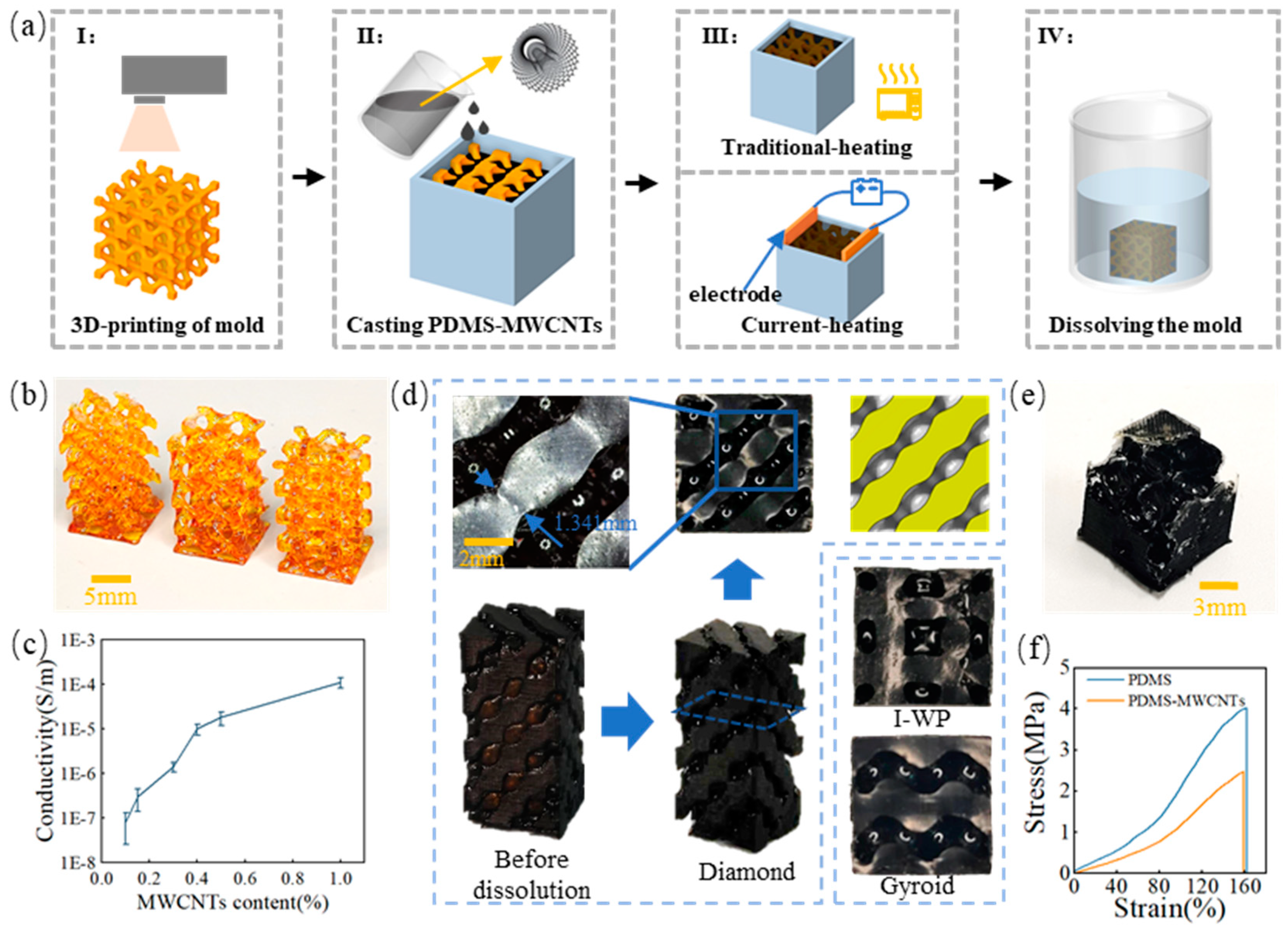
Porous strain sensors made of PDMS-MWCNTs were fabricated using a 3D printed sacrificial mold to shape the PDMS into the desired geometry. The fabrication process is shown in
Figure 2(a). First, the sacrificial molds with different TPMS structures were printed using an LCD 3D printer, which served as templates for creating the desired porous structure in the PDMS-MWCNTs sensors, as shown in
Figure 2(b). Then, the PDMS-MWCNTs matrix phase solution was poured into a regular container containing the LCD sacrificial mold. After the solution had completely penetrated the interconnected pores, the heating process was initiated. The conventional heating method involved heating in the furnace to 100°C for 30 min, while the self-resistance electric heating method required placing a pair of copper electrodes with a voltage strength of 25 V/cm for 10 min on the inner wall of the regular container. The PDMS solution doped with MWCNTs exhibits electrical conductivity, which causes a rapid temperature rise and enables rapid curing.
Figure 2(d) displays the solid PDMS-MWCNTs matrix phases after full cure with various TPMS structures. After the complete curing process, the LCD sacrificial mold was washed thoroughly by immersing it in water, leaving behind the flexible and porous PDMS-MWCNT scaffold. By following this fabrication process, the researchers were able to create porous strain sensors with controlled geometries and properties, paving the way for further investigations into the mechanical and piezoresistive characteristics. The PDMS-MWCNTs scaffold successfully replicated the surface topology of the sacrificial mold, ensuring the transfer of TMPS structure features to the scaffold’s surface. This approach improves localized homogeneity and surface precision compared to direct printing methods. The accuracy of the LCD sacrificial molds was assessed by measuring porosity through dry weighing, as presented in
Table 1. The measured sacrificial phase porosity values deviated by no more than 11.67% from the CAD porosity values. Additionally, the sensing performance of the PDMS-MWCNTs composites is affected by their electrical conductivity.
Figure 2(c) illustrates the electrical conductivity of PDMS-MWCNTs composites with different MWCNTs mass fractions at room temperature. The results indicate that an increase in MWCNT content leads to a corresponding increase in electrical conductivity. Notably, the conductivity rapidly increases by several orders of magnitude when the content reaches the percolation threshold. The electrical conductivity of the PDMS-MWCNTs composites with a mass fraction of 1.0 wt.% MWCNTs was 1.10546 × 10
-4 S/m. However, further increasing the MWCNTs content does not significantly enhance the conductivity. Additionally, higher MWCNTs content increases the viscosity of the PDMS-MWCNTs matrix phase solution, resulting in poor fluidity during the casting process and potential formation of defective edges in the porous material, as depicted in
Figure 2(e). To ensure optimal electrical conductivity and processing performance, a weight ratio of 1 wt.% was determined after careful consideration. Thus, the PDMS-MWCNTs composites used in subsequent tests and characterizations contained 1 wt.% of MWCNTs.
Figure 2(f) presents the tensile stress-strain curves of pure PDMS and PDMS-MWCNTs composites with 1 wt.% MWCNTs. The addition of MWCNTs influences the mechanical properties of PDMS, resulting in a higher tensile strength compared to pure PDMS. However, the difference in elongation at break between the two materials is only 1.8%.
3.2. Self-Resistance Electric Heating Process
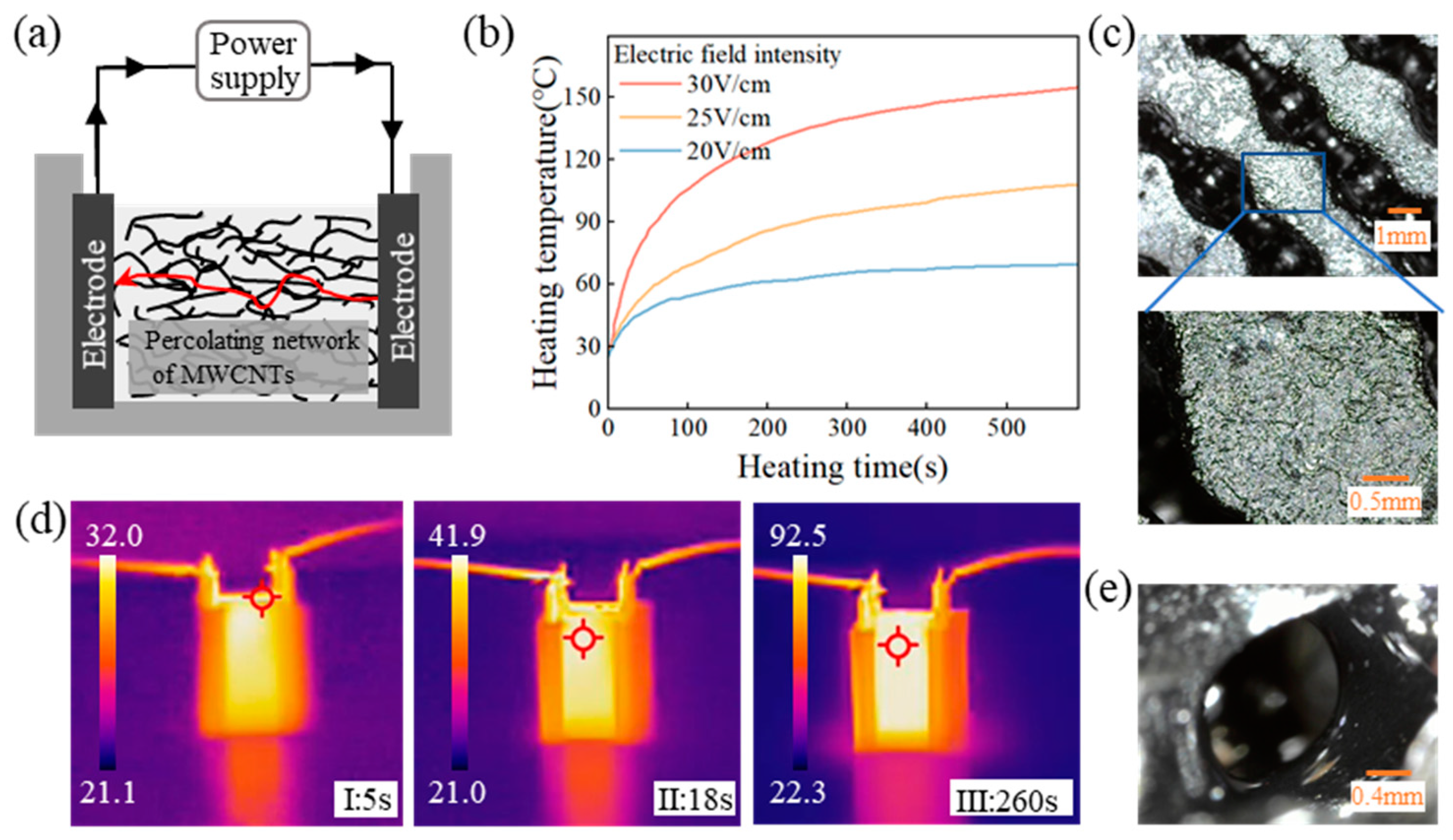
This study aims to compare the traditional heating method, which involves placing the composite solution to an external heat source at 100 °C for 30 minutes, with the self-resistance electric heating method. The latter method, without altering the content, makes use of Joule heat generated by the self-resistance of MWCNTs in PDMS-MWCNTs composites to heat and cure for 10 minutes. A percolation network forms upon reaching a certain MWCNT content, leading to an electro-thermal effect as electric current passes through.
Figure 3(a) illustrates how the internal heat source facilitates the heating and curing process of the composites. During the self-resistance electric heating process, parameters such as current and voltage influence the temperature of the composite material. Thus, to regulate the temperature, the electric field strength at both sides of the copper electrode was adjusted, as shown in
Figure 3(b). The relationship between electric field strength and temperature change was found to be rapid, with the temperature of the composite solution increasing swiftly upon the application of the electric field. Moreover, a higher electric field strength resulted in a faster rate of temperature increase and a higher temperature within the same timeframe. To prevent violent chemical cross-linking reactions in the PDMS, an electric field strength of 25 V/cm was selected for heating, as indicated in the thermal imaging diagram in
Figure 3(d). The experiment demonstrated that the temperature between the electrodes increased rapidly after 5 seconds of applying the electric field, reaching 90 °C within 240 seconds. As the composite material dissipated heat, the rate of temperature rise slowed down, leading to reduced temperature differences within the material. The non-flat surface of the composite material, as shown in
Figure 3(c), resulted from the varying heat capacitance between the composite and electrode materials. However, uniform heat conduction among internal solutions led to minimal temperature variations and smooth internal pores within the prepared composite material, as depicted in
Figure 3(e).
3.3. Compressive Stress-Strain Behavior of Porous Composites
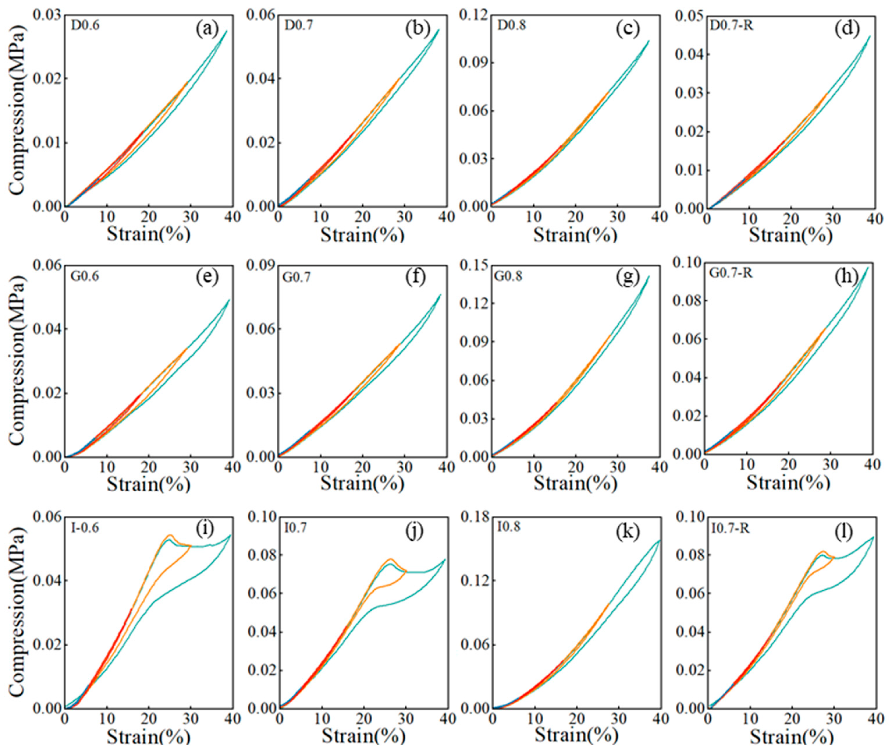
The mechanical behavior of PDMS-MWCNTs porous structures was examined through compression tests to assess the impact of relative density, processing technique, and geometry. The stress-strain curves for all samples are illustrated in
Figure 4(a)-(c). Initially, there is a linear elastic region, and the elastic modulus was determined from the linear section of the curves for all geometries considered, as shown in
Figure 4(d). The study revealed that the I-based structure, with relative densities of 0.6 and 0.7, displayed a plateau of nearly constant stress after the linear elastic region. This suggests that the I-based structure has a higher energy absorption capacity compared to the D and G-based structures. During loading, the pore wall bent, leading to linear elasticity. Upon reaching a critical stress level, pore collapse occurred. At higher strains, either the pores collapsed or the walls made contact, causing further deformation. The steep increase in the stress-strain curve indicated compression within the pore wall material, signaling the onset of densification. Increasing the relative density of the porous composite material resulted in thicker pore walls, enhancing bending resistance and pore collapse stress. The analysis indicated that both the modulus and platform stress were elevated with the increase in relative density. Examining the stress-strain curves of the I-based structure revealed that the structure with a relative density of 0.6 exhibited a lower modulus and platform stress compared to the structure with a relative density of 0.7. Similarly, for the D-based structure, lower relative densities led to smaller strains at the initiation of densification. Reduced distances between pore walls in porous composites with lower relative densities facilitated quicker contact between pore walls, reducing the initial densification strain. The elastic modulus of the porous complex structure fabricated via self-resistance electric heating slightly surpassed that of the model produced through traditional heating. This increase in the elastic modulus of the cured porous complex structure can be attributed to the uniform current conduction and temperature distribution during the self-resistance electric heating process.
Figure 5 displays the stress-strain response curve of the porous composite material under cyclic compressive loading at various strains ranging from 10 % to 40 %. Within the low strain range (10 % to 20 %), the hysteresis zone is narrower. Upon unloading, the matrix phase exhibits near-complete strain recovery, indicating high resilience in the porous composite material. As the strain increases, there is a noticeable shift in the hysteresis loop. To precisely measure the extent of hysteresis in the high strain range (30 % to 40 %), we introduce the hysteresis parameter.
Where S represents the area under the stress-strain curve.
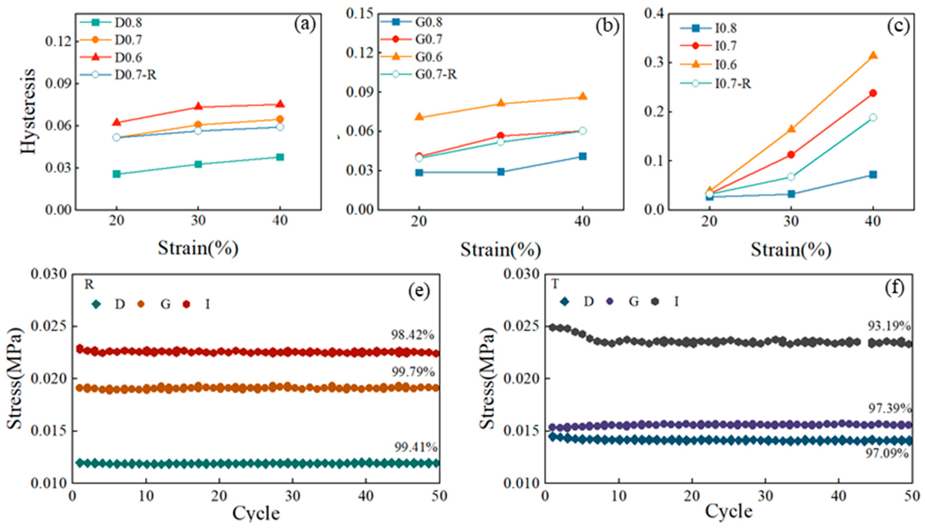
Figure 6(a)-(c) display the hysteresis parameters of porous composite materials with different structures. The findings indicate that higher strains are associated with increased hysteresis parameters, indicating a more significant hysteresis effect as the strain magnitude rises. Structures with higher relative density generally display larger hysteresis coefficients, underscoring the importance of the hysteresis phenomenon. Analyzing the hysteresis coefficients across various strains reveals notable variations in the I-based structures. Particularly, the strain recovery of the I-based structure is slow at high strains, reaching a hysteresis coefficient of 0.31 at a strain of 40 %. In contrast, both D and G-based structures exhibit lag parameters within a relatively small range of 0 to 0.1. However, for the I-based structure, its lag parameters show higher values as the relative density increases to 0.4, indicating a significant influence of relative density on the hysteresis performance of the I-based structure. A comparison of the hysteresis coefficients between the PDMS-MWCNTs scaffold fabricated using the traditional heating method and the self-resistance electric heating method reveals that the former has smaller hysteresis coefficients. This suggests that the current curing process has the potential to partially mitigate the hysteresis phenomenon within the structure itself.
Figure 6(e)-(f) depict the stress attenuation of composite materials after 50 compression cycles across different structures and processes, with the maximum stress values at 10 % strain plotted as a function of cycle numbers. The results clearly show that regardless of geometry, all structures exhibited excellent stability and repeatability after the initial compression cycles. Among structures prepared using two different heating methods, the G-based structure demonstrates the highest maximum stress retention rate, followed by the D-based structure, while the I-based structure shows the lowest retention rate. This indicates that the fatigue effect of the G-based structure under cyclic loading is minimal. Moreover, the maximum stress retention rate of the model fabricated using the self-resistance electric heating process is notably higher than that of the model produced via the traditional heating method. Building on the previous analysis of the compression performance of structures created through self-resistance electric heating, it is clear that the compression performance of the structures surpasses that of structures manufactured through the traditional heating process.
3.4. The Piezoresistive Behavior of Porous Composites
The resistive response in this study is defined as the change in resistance (ΔR) relative to the initial resistance (R₀), expressed as ΔR/R₀ = (R₀ - R) / R₀, where R represents the resistance with compressive stress and R₀ represents the resistance without compressive stress.
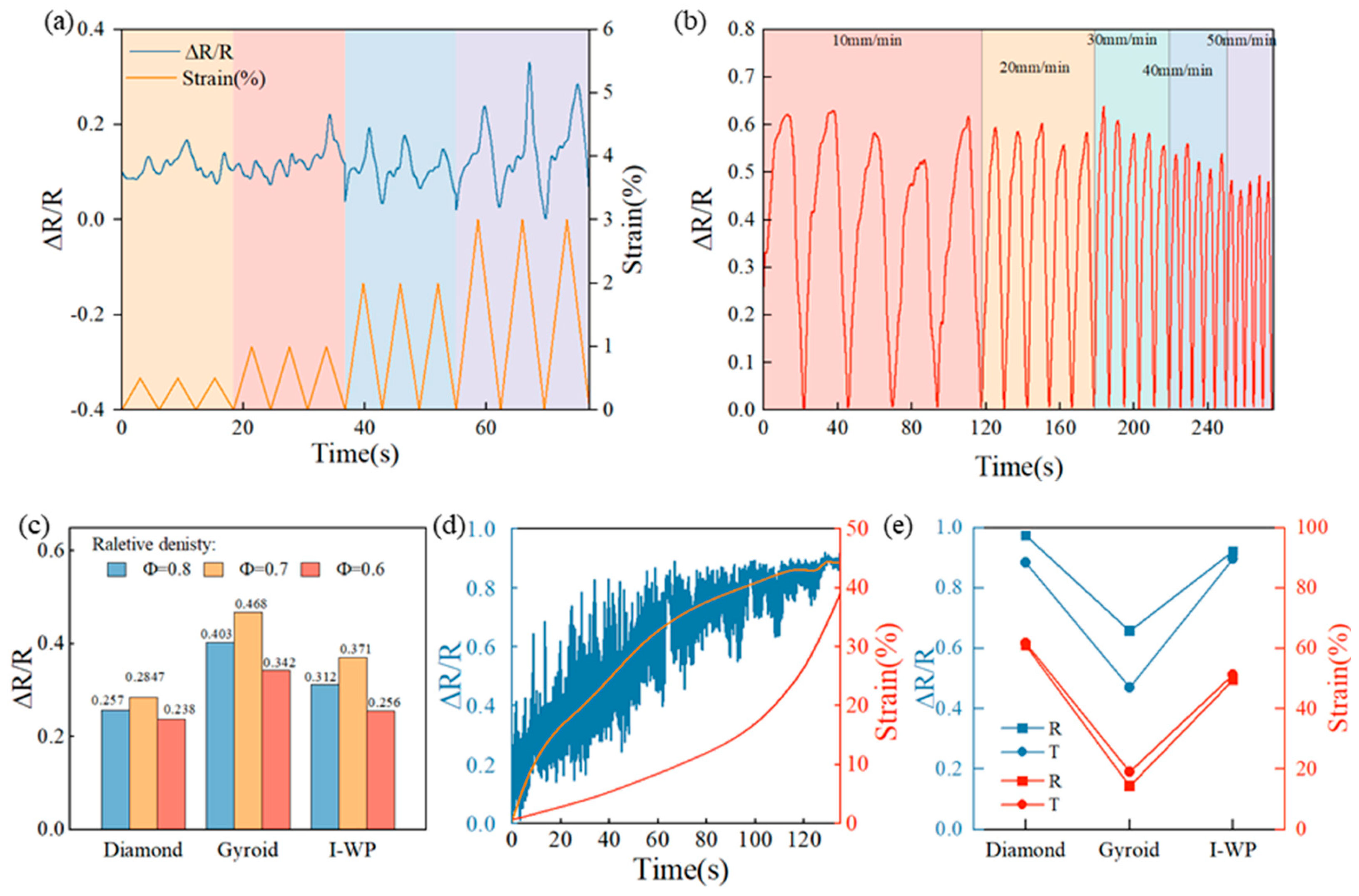
Figure 7(a) illustrates the results of the minimum ultimate response strains for the I-based structure with a relative density of 0.8. The resistance response shows a clear trend of increase and decrease as the strain reaches 1.5 %, corresponding to its behavior. With an increase in strain to 2 %, the resistance response becomes more prominent. For the I-based structure with relative densities of 0.6 and 0.7, the minimum ultimate response strains are 4 % and 3 % respectively. This implies that structures with higher relative densities are more suitable for use as piezoresistors in detecting small deformations. The electromechanical cycling stability of TPMS structures made from PDMS-MWCNT composites was assessed. The samples underwent 5 consecutive compressive cycles (at 20 % strain) at cycling rates ranging from 10 mm/min to 50 mm/min, as shown in
Figure 7(b) for the D0.7 structure. It indicates that the maximum response range does not exceed 11.95 % at different cycling rates, demonstrating excellent stability and signal reversibility. At a compression rate of 50 mm/min, the resistance response value was significantly smaller than at 10 mm/min due to incomplete deformation restoration.
Figure 7(c) presents the resistance response values of all structures with different relative densities at a strain of 10 %. Among the G-based structures, the largest resistance response value is observed. Specifically, the structure with a relative density of 0.7 exhibits a larger resistance response value compared to the structure with a relative density of 0.6, attributed to the higher degree of densification and larger contact surface between the pore walls in the former. Consequently, the resistance value is smaller, leading to a larger resistance response value. However, when the relative density of the structure reaches 0.8, it experiences a high degree of densification. As a result, increasing the strain has less impact on the resistance, resulting in a smaller resistance response compared to a structure with a relative density of 0.7. All samples in the study exhibit negative piezoresistive behavior, indicating that their electrical resistance decrease with increasing strain.
Figure 7(d) illustrates the resistance response of the D0.8 structure, suggesting that when the compressive strain exceeds 20 %, the samples’ internal lattice undergoes compaction and transitions from structural deformation to composite deformation. This leads to a slower increase in the resistance response value, which stabilizes around 0.8 when the strain reaches 30 %. Finally,
Figure 7(e) compares structures prepared using traditional heating and self-resistance electric heating. The results indicate that the maximum ultimate response strain of the self-resistance electric heated structures is greater than that of the traditionally heated structures. Specifically, the structure prepared using the self-resistance electric heating process exhibits a larger maximum response strain and corresponding resistance response value compared to structures prepared using other processes. Among all structures, the G structure exhibits the smallest maximum response strain and the corresponding resistance response value. These findings highlight the effectiveness of the self-resistance electric heating process in improving piezoresistive response.
4. Conclusion
This paper presents a feasible and efficient fabrication process for TPMS porous structures that exhibit improved mechanical recovery. This study utilizes MWCNT-doped composites’ conductivity, and employs self-resistive thermal curing to prepare uniformly heated conductive materials. Piezoresistive sensors of PDMS with complex internal pores were fabricated based on 3D printed sacrificial models. The key conclusions are drawn as follows:
1. Good energy absorption capacity and high elastic modulus were achieved by the composites with serious hysteresis and larger stress loss in repeated cycles. Self-resistance electric heated samples exhibit larger elastic modulus, smaller hysteresis coefficient, and good retention of maximum strain in cyclic tests, indicating better compressive properties compared to externally heat-cured samples.
2. The resistance response is influenced by the relative density of the samples. As the strain increases, the resistance response decreases with a higher relative density. The G-based structure exhibits a smaller maximum response to strain of 18%. It also shows a higher resistance response value than other structures at a 10% strain and under cyclic strain compared to samples cured by an external heat source.
3. Self-resistance electric heating samples exhibit a larger strain range and resistance response value compared to samples cured by an external heat source, emphasizing the importance of selecting the appropriate relative density and structure based on the strain range used.
In conclusion, by selecting an appropriate relative density and structure, utilizing the self-resistive thermal curing technique, sensors with good strain response could be prepared. This research provides valuable insights into the design and optimization of personalized piezoresistive sensors using 3D printing and molding.
References
- CHEN F, LIU H, XU M, et al. Fast-response piezoresistive pressure sensor based on polyaniline cotton fabric for human motion monitoring [J]. Cellulose, 2022, 29(12): 6983-95. [CrossRef]
- LI X, ZHANG T, SONG B, et al. A double-dynamic-bond crosslinked multifunctional conductive hydrogel with self-adhesive, remoldability, and rapid self-healing properties for wearable sensing [J]. Polymers for Advanced Technologies, 2024, 35(1): e6267. [CrossRef]
- XU Q, WU Z, ZHAO W, et al. Strategies in the preparation of conductive polyvinyl alcohol hydrogels for applications in flexible strain sensors, flexible supercapacitors, and triboelectric nanogenerator sensors: An overview [J]. Advanced Composites and Hybrid Materials, 2023, 6(6): 203. [CrossRef]
- FANG Y, ZOU Y, XU J, et al. Ambulatory cardiovascular monitoring via a machine-learning-assisted textile triboelectric sensor [J]. Adv Mater, 2021, 33(41): 2104178. [CrossRef]
- LI Q-Q, WANG G-K, LIANG Z-X, et al. Highly Transparent and Adhesive Poly (vinylidene difluoride) Films for Self-Powered Piezoelectric Touch Sensors [J]. Chinese Journal of Polymer Science, 2022, 40(7): 726-37. [CrossRef]
- LIU Q, LIU Y, SHI J, et al. High-porosity foam-based iontronic pressure sensor with superhigh sensitivity of 9280 kPa− 1 [J]. Nano-Micro Letters, 2022, 14: 1-12. [CrossRef]
- TIAN G, SHI Y, DENG J, et al. Low-Cost, Scalable Fabrication of All-Fabric Piezoresistive Sensors via Binder-Free, In-Situ Welding of Carbon Nanotubes on Bicomponent Nonwovens [J]. Advanced Fiber Materials, 2023: 1-13. [CrossRef]
- GAO Y, YAN C, HUANG H, et al. Microchannel-confined MXene based flexible piezoresistive multifunctional micro-force sensor [J]. Advanced Functional Materials, 2020, 30(11): 1909603. [CrossRef]
- HABIB F, IOVENITTI P, MASOOD S, et al. Fabrication of polymeric lattice structures for optimum energy absorption using Multi Jet Fusion technology [J]. Materials & Design, 2018, 155: 86-98. [CrossRef]
- GAN X, WANG J, WANG Z, et al. Simultaneous realization of conductive segregation network microstructure and minimal surface porous macrostructure by SLS 3D printing [J]. Materials & Design, 2019, 178: 107874. [CrossRef]
- PENG S, GUO Q, THIRUNAVUKKARASU N, et al. Tailoring of photocurable ionogel toward high resilience and low hysteresis 3D printed versatile porous flexible sensor [J]. Chemical Engineering Journal, 2022, 439: 135593. [CrossRef]
- IMANIAN M E, KARDAN-HALVAEI M, NASROLLAHI F, et al. 3D printed flexible wearable sensors based on triply periodic minimal surface structures for biomonitoring applications [J]. Smart Materials and Structures, 2022, 32(1): 015015. [CrossRef]
- DAVOODI E, MONTAZERIAN H, HAGHNIAZ R, et al. 3D-printed ultra-robust surface-doped porous silicone sensors for wearable biomonitoring [J]. ACS nano, 2020, 14(2): 1520-32. [CrossRef]
- RONCA A, ROLLO G, CERRUTI P, et al. Selective Laser Sintering Fabricated Thermoplastic Polyurethane/Graphene Cellular Structures with Tailorable Properties and High Strain Sensitivity [J]. Applied Sciences, 2019, 9(5): 864. [CrossRef]
- PARé A, CHARBONNIER B, TOURNIER P, et al. Tailored three-dimensionally printed triply periodic calcium phosphate implants: a preclinical study for craniofacial bone repair [J]. ACS biomaterials science & engineering, 2019, 6(1): 553-63. [CrossRef]
- CHARBONNIER B, MANASSERO M, BOURGUIGNON M, et al. Custom-made macroporous bioceramic implants based on triply-periodic minimal surfaces for bone defects in load-bearing sites [J]. Acta Biomaterialia, 2020, 109: 254-66. [CrossRef]
- WEI P, LENG H, CHEN Q, et al. Reprocessable 3D-printed conductive elastomeric composite foams for strain and gas sensing [J]. ACS Applied Polymer Materials, 2019, 1(4): 885-92. [CrossRef]
- KIM K, PARK J, SUH J-H, et al. 3D printing of multiaxial force sensors using carbon nanotube (CNT)/thermoplastic polyurethane (TPU) filaments [J]. Sensors and Actuators A: Physical, 2017, 263: 493-500. [CrossRef]
- ALSHARARI M, CHEN B, SHU W. Sacrificial 3D printing of highly porous, soft pressure sensors [J]. Advanced Electronic Materials, 2022, 8(1): 2100597. [CrossRef]
- SIXT J, DAVOODI E, SALEHIAN A, et al. Characterization and optimization of 3D-printed, flexible vibration strain sensors with triply periodic minimal surfaces [J]. Additive Manufacturing, 2023, 61: 103274. [CrossRef]
- PENG S, WANG Z, LIN J, et al. Tailored and highly stretchable sensor prepared by crosslinking an enhanced 3D printed UV-curable sacrificial mold [J]. Advanced Functional Materials, 2021, 31(10): 2008729. [CrossRef]
- ATHANASOPOULOS N, KOUTSOUKIS G, VLACHOS D, et al. Temperature uniformity analysis and development of open lightweight composite molds using carbon fibers as heating elements [J]. Composites Part B: Engineering, 2013, 50: 279-89. [CrossRef]
- LIU S, LI Y, SHEN Y, et al. Mechanical performance of carbon fiber/epoxy composites cured by self-resistance electric heating method [J]. The International Journal of Advanced Manufacturing Technology, 2019, 103: 3479-93. [CrossRef]
- ZHANG B, LI Y, LIU S, et al. Layered self-resistance electric heating to cure thick carbon fiber reinforced epoxy laminates [J]. Polymer Composites, 2021, 42(5): 2469-83. [CrossRef]
|
Disclaimer/Publisher’s Note: The statements, opinions and data contained in all publications are solely those of the individual author(s) and contributor(s) and not of MDPI and/or the editor(s). MDPI and/or the editor(s) disclaim responsibility for any injury to people or property resulting from any ideas, methods, instructions or products referred to in the content. |
© 2024 by the authors. Licensee MDPI, Basel, Switzerland. This article is an open access article distributed under the terms and conditions of the Creative Commons Attribution (CC BY) license (http://creativecommons.org/licenses/by/4.0/).
