
You are currently viewing a beta version of our website. If you spot anything unusual, kindly let us know.
Preprint
Article
Environmental Constraints for Intelligent Internet of Deep-Sea/Underwater Things Relying on Enterprise Architecture Approach
Altmetrics
Downloads
72
Views
36
Comments
0
A peer-reviewed article of this preprint also exists.


This version is not peer-reviewed
Abstract
Through the use of Smart Sensor Networks (SSN), Marine Observatories (MO) provide continuous ocean monitoring. Deployed sensors may not perform as intended due to the heterogeneity of SSN devices’ hardware and software when combined with the Internet. Hence, SSN are regarded as complex distributed systems. As such, SSN designers will encounter challenges throughout the design phase related to time, complexity, sharing diverse domain experiences (viewpoints), and ensuring optimal performance for the deployed SSN. To this end, we describe in this article how we extended our previously proposed ArchiMO meta-model and design tool by extending an Enterprise Architecture Framework based on the ArchiMate Modeling Language. This extension proposes the incorporation of new Underwater Environmental Constraints (UEC) for SSN in ArchiMO which is coupled with the fusion of sensors with Artificial Intelligence. This serves as the basis for generating a new version of our ArchiMO design tool, which incorporates the new added constraints and invokes the AI created Database. To illustrate our proposal, we use the newly generated ArchiMO to create a model in the MO domain. Furthermore, we use our self-developed domain-specific model compiler to produce the relevant simulation code. Throughout the design phase, our approach contributes to handle and control the uncertainties and variances of the provided quality of service that may occur during the performance of the SSN, hence reducing the design activity’s complexity and time. It provides a way to share the different viewpoints of the designers in the domain of SSN.
Keywords:
Subject: Computer Science and Mathematics - Computer Science
1. Introduction
Intelligent Internet of Underwater Things (IIoUT) is proposed for sensing, collecting and storing underwater information [1]. IIoUT is an application based on Underwater Smart Sensor Networks (USSN) since it enhances deep sea monitoring, tracking various aquatic creatures, and ocean monitoring and observation systems, which are based on acoustic communication [2,3]. Logically, (USSN) operates in the same manner as the Smart Sensor Networks (SSN) that is not submerged in water, providing the same services, such as Deep Sea/Underwater monitoring. The USSN deployment phase, however, differs from the non-underwater phase in that experts must consider certain underwater environmental constraints during this phase. Failure to do so could have a negative impact on the performance of the entire SSN and result in improper underwater deployment of all SSN components, including servers, sensors, cables, and other physical and telecommunication components [4,5].
Smart Sensor Networks (SSN) is composed of artificial intelligence (AI) and several specialized sensors [6]. This demonstrates how Smart Sensors are connected to various Smart Fusion Servers with AI Databases [7] through the use of Distributed Fusion Architecture (Figure 1) [8] to carry out multiple tasks like collecting, processing, and storing data continuously and permanently from various sensors dispersed throughout various locations within the same network. Therefore, the primary job of SSN is to gather environmental data and transmit it to a centralized location or processing system, such a Smart Fusion Server, for evaluation and decision-making. By now, it ought to be obvious how challenging it is to create USSN since various resources contribute to its intricacy. Nonetheless, in this article, we specifically discuss the following [5,9,10]: since a distributed system’s architecture consists of many heterogeneous components, it is a complicated system by itself. This indicates that it will be challenging to analyze, design and deploy USSN. Certainly, you can expand upon the importance of the design of the USSN and the potential consequences of design mistakes throughout the deployment phase of any USSN project. This is due to the fact that, in the USSN life cycle, the design phase is performed first, coming before the deployment phase.
We focus our research on the applications for the Marine Observatories (MO) which have a common concept but employ diverse technologies. More specifically, our research’s focus is dedicated on the Marine e-Data Observatory Network (MeDON)(Figure 2).
The MeDON project [11] relies on USSN in order to enable continuous ocean observation. MeDON uses various communication protocols (REST, SOAP, and executive ones) to connect its various physical and logical components (e.g., Smart Sensors, Smart Fusion Servers, and Object Localization Algorithms) and together, these sensors gather data, which is subsequently transferred to the assigned workstations where it operates as a complex distributed information system. This indicates that the structure of MeDON [11] is similar to that of the USSN system, meaning that the issues we previously discussed regarding the complexity and challenges encountered during the USSN project’s design and deployment also arise during MeDON’s design and deployment.
Accordingly, our scope in MeDON project revolves around the intricate design of the USSN and the associated mechanisms for locating underwater moving objects. This aspect of the project is critical for achieving its overarching goals, which include monitoring and understanding the marine environment. According to [12], the complexity of the design phase is due to: (1) The several expertise domains (information systems, business process, and underlying infrastructure modeling) that the designer(s) must possess in order to model and explain such systems; (2) The MeDON/USSN Information System’s distributed software structure (Figure 2) is characterized by the fact that individual components, such as Smart Fusion Servers and Smart Sensors, are accountable for meeting specific requirements. (3) High levels of accuracy that must be met by the designer(s) for each component that must be deployed underwater throughout the design phase, especially for the physical components such as Smart Sensors. For this purpose, an information system like MeDON or any other USSN has a complicated design phase which demands meticulous attention to detail. In light of this, mistakes/errors committed during this vital phase might have a significant and negative impact on the project’s overall performance.
These errors or sub-optimal sensor network designs may arise the following outcomes [5,9,10]: (1) inaccurate and incomplete data collection. This undermines the project’s ability to gather reliable information about the underwater environment, including the quality of services provided such as the movement patterns of marine mammals/underwater moving objects and the state of the ecosystem; (2) operational inefficiencies. This can introduce an increased energy consumption, high maintenance costs, and reduced sensor network lifespan. These inefficiencies can strain project resources and hinder its long-term sustainability; (3) data misinterpretation and misalignment with project objectives. This may draw incorrect conclusions or fail to identify critical environmental trends, hindering scientific understanding; (4) wasted resources in terms of designers and analysts. This is costly due to the expenses for redesign and retrofitting. This not only drains project resources but also leads to delays in deployment, potentially impacting the project’s ability to meet deadlines and objectives; (5) project reputation. This may make the project less attractive to collaborators, stakeholders, and funding agencies; (6) inappropriate/inaccurate deployment. This could result in redeploying all or some of the SSN’s components. This is costly due to the substantial expenses for the procurement of specialized boats, maritime cables, hydrophones, smart data fusion servers, and the engagement of diving experts.
In terms of our contribution in the MeDON project, we are involved by underwater tracking moving objects. In order to deliver such high-level services, we must avoid the outcomes listed in the preceding section, particularly the one about proper and accurate deployment. Otherwise, this has a negative impact on the overall performance of the MeDON project (e.g., inaccurate object localization in our case).
For this purpose, our main objective is to simplify the work of SSN designers in order to prevent errors during the deployment phase and ensures optimal performance across the whole SSN.
As per the findings of [4] and [5], certain Underwater Environmental Constraints (UEC) must be taken into account when deploying USSN. If this doesn’t occur, there will be a detrimental effect on the project’s overall performance due to the intricacies and increase the likelihood of errors during the deployment phase. Furthermore, it has a detrimental impact on sensor algorithm performance, diminishing its optimization. For example, Smart Sensors (Smart Hydrophones in our case) may only detect raw data and then transfer it to other devices (Smart Fusion Servers in our case) within the same networks without any analysis. This may occur when underwater sensors are not deployed in the proper location (e.g., appropriate operable depth). In this case, the sensor may detect and transmit erroneous and useless data to other devices because sensors function differently depending on the operable depth. For instance, it may lead to incorrect object location detection [13,14]. It’s crucial to recognize the risks that will inevitably present during the deployment phase as a result of design phase mistakes.
According to [5], Architecture (2D or 3D), Salinity levels and Operable depth are the essential Underwater Environmental Constraints (UEC) that must be adhered to during the deployment phase of USSN. Thus, there is a requirement for seamless integration between the MO information system and the communication system (e.g., IMS) [15].
In order to tackle all of the aforementioned issues and to reach our main objective, our research question revolves on improving the SSN’s design phase and streamlining the intricate details of the deployment phase.
We present an extension to the ArchiMO meta-model and design tool (Figure 3) (Figure 4) in this work. ArchiMO was previously developed and published in [2,3,16]. ArchiMO meta-model enables us to generate a specific design tool that is coherent with Archi tool [17] but contains additional concepts, elements, constraints and relations that are specific to the MeDON/MO domain and for data fusion concepts [8], ArchiMO design tool. In order to create this generation, we have extended the Eclipse Modeling Framework (EMF) based on the fundamental principles of Model-Driven Engineering (MDE) [18]. EMF is based on ArchiMate, an Enterprise Architecture modeling language consisting of three layers: application, business, and technology layers.
Briefly, the generated design tool ArchiMO helps the SSN designers to model USSN system and avoid syntax errors that may be made during the design activity.
In this article, our extension’s approach is based on the utilization of domain-specific modeling languages (DSML). We have extended ArchiMO meta-model (abstract syntax), concrete syntax, and design tool by incorporating new Underwater Environmental Constraints (UEC) [5]. This extended ArchiMO represents the specificity of the SSN domain in terms of certain UEC that are required for the proper deployment of USSN to ensure its appropriate performance and functioning. Regarding the generation process of a new version for our ArchiMO, it is similar to what we conducted in our previous research in [2,3] and [16], which are discussed in the previous section.
In technical terms, the extension of ArchiMO is carried out by: (1) using the ArchiMate modeling language together with learning control (which is one application of Artificial Intelligence) that is based on an AI Database and includes structured data that are necessary for designing and deploying AI models in order to properly model USSN systems [7]. AI Database, a relational database is created containing various related entities that describe how the data of the proposed UEC could be inserted, modified, and retrieved in an organized and structured manner using a relational database management system (MySQL) based on Structured Query Language (SQL); (2) implementing Java code in the EMF (e.g., JDBC connection string, etc.) in order to invoke the values of UEC during the design activity.
Next, we generated an updated version of our ArchiMO design tool with the three additional UEC that we have introduced. This tool (Figure 4) provides SSN designers with a set of reusable graphical elements and concepts that follow both ArchiMate and MO concepts. Next, we utilize the latest generated version of ArchiMO to create a MO model, to ensure that the newly implemented constraints are effectively functioning while creating Smart Sensors during the design phase.
One notable characteristic of Enterprise Architecture (EA) frameworks is their ability to facilitate the sharing of multiple viewpoints [20]. This, in turn, simplifies the complexity of individual views, making them more manageable. However, Enterprise Architecture frameworks also introduce interoperability challenges when attempting to integrate various viewpoints with their respective dedicated software [20].
Connecting our extended ArchiMO meta-model with the IP Multimedia Subsystem (IMS) meta-model serves to seamlessly integrate the various Smart Sensors and Smart Fusion Servers within the sensor network with the broader information system via the core network [21,22]. Subsequently, we apply our design model to a model compiler, which generates simulation code that can be executed directly within the NS-3 network simulator.
The article content is organized as follow: In Section 2, we present the related work that is connected to the design tools. Section 3 presents MO project. In Section 4, we present MDE fundamentals, DSML, ArchiMate and AI Databases. Section 5 explains the abstract syntax, concrete syntax, semantics and AI Database of the proposed DSML including UEC. In Section 6, we present the newly added UEC along with how it is generated with ArchiMO design tool, as well as and the simulation approach. Then, in Section 7, we conclude and discuss our future work.
2. Related Work
We provide the relevant work in relation to the design tools in this section. We are interested in the following concerns, which we will define and examine in this section in relation to the concept of Architectural Description Languages (ADL) [23,24,25,26] and their design tools: (C1) utilizing a language’s syntax or language structure to prevent errors at the design level; (C2) various points of view1 that are reflected in the architectural description [27]; (C3) design tool extensibility; (C4) Variability of components; (C5) Platform for execution and testing.
Concerning the concern of preventing errors, the expanded design tool works to stop problems before they happen, saving the designer the trouble of fixing them later. The sources for this error prevention strategy include [28,29], and [30]. Similar to our methodology, it is circumvented by utilizing the abstract syntax (our suggested concepts), in which we have established and included our particular concepts, constraints and relations.
Regarding the concern of many viewpoints, the extended design tool offers the designers a variety of viewpoints based on their domains of experience. The design tool in [28,29,30] offers only one viewpoint to suit software development activities. It is not possible for various designers to share a design created with this design tool. This is because there is no architectural framework, which produces a design tool that complies completely with the aforementioned ooncer [31]. Our approach takes this into account because of the several EA standard layers that distinguish between different points of view.
As for the extensibility concern, adding new concepts and restrictions to an existing design tool is made possible through the extension of a meta-model [28,29]. As demonstrated in [32] and [33], our method achieves this by adding additional constraints to the ArchiMate meta-model and creating a new design tool that incorporates these constraints.
Regarding the heterogeneity concern, which is the presence of various components and communications associated with various activities and contexts. In [28,29], and [30], we encounter this heterogeneity in the software components and models. The diversity of components in our approach is seen in our MO model, which has several Smart Sensors linked to numerous Data Fusion Servers.
Concerning the platform for the execution test, we may find an integration between two distinct platforms, as shown in [34], to provide an automated execution test of a given complex model. Additionally, as shown in [28,30], and [29], there are platforms on which the designer is unable to test and validate his models or instances. Nevertheless, as per [32], our approach enables us to verify the generated models on an executable platform that is integrated inside the same framework that facilitates model construction (see to section VI). For instance, messages can be sent and received between Smart Sensors and Fusion Servers using (IMS).
3. Marine Observatories
An analog or digital transducer paired with a CPU and a communication interface is called a smart sensor. It is made composed of a controller or processor that supports some intelligence, a transducer element, and an electrical signal conditioning system all combined into one package [35]. This type of sensor is known as a system-on-a-chip (SoC) because it combines electronics and a transducer (which changes form) element onto a single silicon chip. The primary goal of combining electronics and sensors is to create an integrated sensor, often known as a smart sensor. As a result, although basic sensors lack an inbuilt Digital Motion Processor (DMP), smart sensors do. A microprocessor built into the sensor is called a DMP. It permits on-board processing of the sensor data by the sensor.
In the context of the Marine e-Data Observatory Network (MeDON) project (Figure 2), the Smart Sensors that should be employed in the project’s development and implementation will resemble the architecture depicted in (Figure 5).
Many advantages come from integrating a smart sensor into a MeDON project [37]; here are a few of them: (1) The sensor’s input is processed by the embedded CPU to produce meaningful information. This indicates that the device’s Multiple Controller Unit (MCU) can compute the input data without using up all of its energy. By doing this, the device’s power consumption from the base sensors is reduced. (2) The real-time data gathered by these sensors can be instantly linked to other devices and transferred via an Application Programming Interface (API) without the need for time-consuming intermediate processes. (3) It may receive input by recognizing different data parameters from several information sources, and then utilize built-in routines to determine a particular combination of inputs before sending the data to networks that are currently active. (4) It makes it possible for information to be collected automatically, which reduces false noise that is recorded alongside accurate information.
Consequently, a smart sensor can gather environmental data more precisely and with lower false noise [1]. In the context of Internet of Things (IoT) technologies (like MeDON), sensors and smart sensors are essential components. Fundamentally, sensors aid in the gathering and processing of data used by IoT devices. In the IoT domain, a smart sensor can then make certain decisions.
Future big data collecting systems will be developed using Underwater Smart Sensor Networks with a focus on environmental data acquisition [11,38,39]. They enable the interchange and processing of data between the various devices (e.g., Smart Fusion Servers, Smart Sensors). We can install software components on all of these devices to handle and store the data and information. As long as the network is functioning properly, these components can provide new features or services such as the localization of marine mammals or underwater moving objects as the Marine e-Data Observatory Network (MeDON) project (Figure 2), which provides an example of a Marine Observatories (MO). To provide such services, SSN ought to consist of a network of specialized heterogeneous devices and communications infrastructure that can record and monitor data at different locations with varying levels of computational and communication capabilities with different communication protocols.
In this situation, to provide such a localization service, the designer should be able to integrate N acoustic Smart Sensors (Smart Hydrophones) connected to Y Smart Fusion Servers to allow for data interchange between them. This exchange’s scenario is predicated on the concept of Distributed Fusion Architecture (DFA) [8] (Figure 1). These servers process the acoustic data that the Smart Hydrophones collected before disseminating it over the network. The same database is used by all servers to store data to be analyzed to become information. The web server, where a web application is configured, receives the processed and analyzed data from the databases servers. As a result, the web server transmits, via a graphical user interface (Figure 2), to the web clients the information picked up by the hydrophones, such as the voice of the dolphin.
This implementation gives priority to modularity in its architecture. Develop and deploy the application across numerous sites more easily when it is modular. It is required as we are working with distributed systems [8] (Figure 1). In order to achieve the requested modularity we choose to break the system down into several components. There are two groups of components (Figure 6): (1) The core components; (2) The functional components. The core components provide the data flow (C6 Observatory Manager), the find data and part of the store data functionnality (C3 Data Management). The core components should be deployed BEFORE all other components. Besides the component C6 Observatory Manager should be the first one to be deployed. Then it is possible to deploy the component C3 Data Management. The other components can then be deployed. Furthermore, as depicted in (Figure 7), MeDON has been physically deployed in many places by connecting the various components using SOAP Web Services.
The terms "hydro" (water) and "phone" (sound) combine to form the word hydrophone. To put it simply, a hydrophone is an underwater microphone that is used to measure sound in the water [40]. A brief overview of the features, types, and uses of hydrophones is provided in (Figure 8) [40].
Acoustic waves are considered the most efficient carriers for underwater applications and long-distance information transmission (e.g., MeDON) due to their significantly longer propagation distances in water compared to electromagnetic waves. Additionally, because of issues with multipath propagation, time fluctuations in the communication channel, short bandwidth, and the need for powerful signals, the usage of electromagnetic wave-based communications is severely restricted underwater. For this reason, sound has been applied extensively in the undersea field up to this point [40].
In the field of underwater acoustic measurement, several hydrophone structures with various operation mechanisms are employed to fulfill the various needs of the circumstances. These gadgets include underwater military weaponry and SONAR (Sound Navigation and Ranging) equipment in addition to standard commercial electronics.
A 2D or 3D array/network of hydrophones can be utilized in place of a single hydrophone, depending on certain approaches and algorithms, to enhance performance and provide additional features in both active and passive modes.
4. Model Driven Engineering (MDE), Domain Specific Modeling Languages (DSML) and Artificial Intelligence (AI) Databases
They are broken down into three sections:
4.1. Model Driven Engineering (MDE)
MDE [27] is ”a software development method which focuses on creating and exploiting domain models. It enables the use of models for simulating, estimation, understanding, and communication. The modeling idea and model transformations in MDE aid in managing complexity. Modeling aids in high-level abstraction of the design, and model transformation aids in the generation of design tools.
In our approach, modeling tools follow the constraints and represent the concepts that are defined in the meta-model2. Similar to programming languages, it makes it possible to instantiate lots of conforming models [42]; numerous of programs can be implemented relying on a specific programming language (e.g., C, C++, Java, etc).
The modeling and meta-modeling processes are made easier by the powerful environment offered by the Eclipse IDE, which also supports a wide range of model transformation languages.
Model transformations enable the direct and automatic generation of design tools and simulation programs while taking into account meta-models and model instances. Each model transformation is based on a set of guidelines that define and regulate the transformation procedure. Models that adhere to various meta-models may be mapped by the transformation rules (on the same abstraction level) such as ATL [43], or map between different domains using one meta-model for the source model to generate texts/codes (e.g., XPAND [44]).
In our case (Figure 3), the input model reflects the design at a very high level of abstraction, and the meta-model (the extended ArchiMate meta-model), which represents the abstract syntax [27,45]. Our automated code generation approach connects the simulation scripts and the design model directly [46]. As a result, it minimizes implementation errors and shortens the implementation time for complicated simulation programs.
4.2. Domain Specific Modeling Languages (DSML)
According to [47], Domain-Specific Modeling Languages (DSML) allow designers from various fields and backgrounds to take part in software development tasks and to express their own requirements using domain concepts. The three parts of a DSML [48] are semantics, abstract syntax, and concrete syntax. The relationship between modeling concepts is defined by the abstract syntax.
Concrete syntax comes in a variety of forms, including visual, textual, XML-based, etc [49]. The representation of the abstract syntax is defined by a set of rules that are connected to the concrete syntax. Semantics, which are connected to abstract syntax, define a model’s meaning. They serve as well-defined model rules that limit the use of the concrete syntax [48]. According to [49], modeling languages are used to describe systems with a high level of abstraction. We define distributed systems for MeDON/MO in connection to our goals. UML only has one layer that encompasses all of the design concepts, and these concepts are too broad to meet our needs. For further information, see Horton [50]. Because it relies on the TOGAF framework and can describe systems from the IT domain and share multiple points of view during the design process, ArchiMate is the modeling language we chose [27]. Additionally, as of January 2018, the ArchiMate meta-model by The Open Group can be used to generate the most recent iteration of the NATO Architecture Framework (NAF v4)[31]. A standard for creating architectures is NAFv4.
Enterprise Architecture (EA) framework is a fundamental component of ArchiMate [27,51]. The system design is broken down into the business, application, and technological layers. According to our methodology, we show these levels as follows:
- Business Layer: describes the roles and responsibilities of the end user. It explains how the end-user views the service operations and how they flow together.
- Application Layer: describes the features and software parts of the service. It explains the capabilities and method of operation of the system being studied.
- Technology Layer: describes the underlying platform’s hardware components, topology, signaling protocols, and functions. It provides information about the execution platform’s functionalities that the application layer’s functions can utilize.
4.3. Artificial Intelligence (AI) Databases
AI databases are designed to handle three different types of data: unstructured, semi-structured, and structured. All of these data types are necessary for creating and utilizing AI models.
The many formats in which information is saved and structured are referred to as "types of data" when discussing AI databases. These formats are crucial for processing, analyzing, and using data to create AI models [7].
Structured data is set up in a very clear and organized way. Each data entry contains particular fields and features with clearly defined data types, and the system follows a transparent data model.
Tables, spreadsheets, and classic relational databases all contain organized data as examples. The links between the data elements are well specified in structured data, which makes it simple to query and analyze with established techniques. Structured data for AI applications might include numbers, categorized labels, dates, and other clearly specified information.
5. Contribution
Domain specificity (MO) in our situation is represented by concepts/operations and constraints that are generally represented by a meta-model of Domain Specific Language (DSL) [49]. Information systems are modeled and described using a modeling language that is provided by a meta-model. It includes the language’s abstract syntax, which explains its constraints in terms of the concrete syntax that the design tool can use.
Two views comprise our previous proposed ArchiMo meta-model ([16](Figure 3): one for the application layer and another for the business layer. In order to connect the information system with the core network at the technological layer, we rely on a meta-model for IMS that offers an underlying platform in [16].
In this section, we present our contribution to extend the ArchiMO meta-model that we previously developed and published in [2,3,16]. Our previous contribution ArchiMO is presented in (Figure 3) and (Figure 4).
ArchiMO meta-model represents the domain specifications of MO. It enables us to generate a specific design tool that is coherent with Archi tool [17] but contains additional concepts, elements, constraints and relations that are specific to the MeDON/MO domain and for data fusion concepts [8]. Briefly, the generated design tool ArchiMO helps the SSN designers to model information systems such as MeDON and avoid syntax errors that may be made during the design activity.
Our primary goal in writing this article is to improve ArchiMO’s intelligence by increasing its ability to identify mistakes that SSN designers may have made when creating and developing MO models. Additionally, to keep the entire deployed SSN operating at peak performance and avoid any malfunction.
To reach this goal, we have extended ArchiMO meta-model (abstract syntax), concrete syntax, and design tool by incorporating new Underwater Environmental Constraints (UEC). This extended ArchiMO represents the specificity of the SSN domain in terms of certain UEC that are required for the proper deployment of USSN to ensure the appropriate performance and functioning of SSN [4,5,9,10,13,14]. Additionally, it enables us to generate a new and an updated version of our ArchiMO design tool that is consistent with Archi and includes the new UEC.
Relying on [4,5,13] and according to MeDON project [11] (Figure 2), SSN information system must meet certain UEC requirements in order to be deployed properly. This implies that every physical component of the SSN, including the Smart Sensors (SS) and Smart Fusion Servers (SFS), must comply with these UEC. Otherwise, inadequate service quality on each deployed component level (e.g., inaccurate/useless detected data by the underwater SS) and overall SSN performance (e.g., erroneous/useless gathered, analyzed and treated data that is provided by underwater SFS after receiving data from different underwater SS) may result from this. As a result, we identify the following interrelated and depend on each other UEC that need to be taken into account when deploying underwater SS/SFS to ensure the appropriate performance and functioning of SSN [9]: (1) Architecture (2D or 3D); (2) Salinity level; (3) Operable Depth.
SSN designers need to be aware of the various ways in which these UEC are inter-dependencies and related in terms of values [4] such as the two following scenarios: (1) If the experts want to deal with 3D architecture, they should be aware of the salinity level (e.g., sea or shallow water), at which they wish to install the physical components of the USSN (e.g., SS/SFS). The deployment of SS/SFS should be carried out at a depth of 10920 meters underwater if the salinity level is sea. However, the deployment of SS/SFS should be carried out at a depth of 3000 meters underwater if the salinity level is shallow water; (2) If the experts want to deal with sea salinity level, they should be aware of architecture’s type (e.g., 2D or 3D), at which they wish to install the physical components of the USSN. The deployment of SS/SFS should be carried out at a depth of 110 meters underwater if the architecture is 2D. However, The deployment of SS/SFS should be carried out at a depth of 10920 meters underwater if the architecture is 3D.
In this article, we have extended our ArchiMO meta-model by incorporating new UEC. In practice, we have specialized the definition of the Smart Sensors according to the UEC. This specialization involves creating an AI Database (Figure 10) that is connected to the Eclipse Modeling Framework (EMF) by implementing java code in the EMF (e.g., JDBC connection string, etc.). Furthermore, extending the Eclipse Modeling Framework (EMF), which is based on the ArchiMate and ArchiMO meta-models, by implementing Java code (e.g., control instructions such as if, else, etc).
Then, in accordance with Archi, we have generated an upgraded version of our ArchiMO design tool (Figure 4) that incorporates the new proposed UEC. Additionally, when using this tool, the built and implemented AI Database is invoked by the implemented java code in order to retrieve data (Figure 10) related to UEC that must be respected by SSN designers (Figure 11)(Figure 12). This implementation is the grammar of the new proposed DSML.
To visualize and having a graphical view for the added UEC, we utilized the generated version of ArchiMO during the creation of a MO model. This design tool helps the designer to model the information system in a highly abstract way by drag and drop the elements (e.g., Smart Sensors) and relations from the palette. The potential to employ the newly added UEC and their proper operation are verified during model editing in the following way: when a designer taps the SS icon in the ArchiMO palette, our extended ArchiMO design tool uses the AI Database to extract the relevant UEC’ values and the targeted SS’s accompanying constraints according to a valid primary key that should be assigned by the designers. At this stage, ArchiMO continue asking the SSN designer to enter the right primary key of the targeted SS then the right Architecture, Salinity Level and Operable Depth in order to compare and verify the entered values of UEC with the retrieved values from the AI Database. At this point, if the SSN designer executes one of the next two scenarios, he will obtain confirmation from the framework that he can deploy the Smart Sensor (Figure 11): (Architecture: 3D, Salinity Level: Sea, Operable Depth: 10920) or (Architecture: 2D, Salinity Level: Sea, Operable Depth: 110). In the opposite scenario, as seen in (Figure 12), the SSN designer will be informed that he is unable to deploy the Smart Sensor due to one or more improper UEC. Consequently, these constraints prevent the SSN designers from inputting the improper UEC for SS/SFS/Fixed Nodes.
Our contribution replies to the concerns that we have presented in section II by: (C1) By enabling the SSN designers to cease entering the incorrect UEC for SS (Figure 11)(Figure 12), ArchiMO helps to avoid potential syntax errors during the design activity; (C2) ArchiMO design tool considers different domains of experience, each domain expert works in a specific layer (Business, Application or Technology) as the model created in section VI. It provides three layers according to each domain specificity; (C3) We have expanded the Eclipse Modeling Framework (EMF), an open and standard framework based on the ArchiMate and ArchiMO meta-models, by implementing java code and building an AI database that is invoked. Subsequently, we have generated an upgraded version of our design tool (Figure 4) to have a specific one like ArchiMO that incorporates the new proposed UEC; (C4) ArchiMO design tool provides the ability to deploy SSN models (the model created in section VI) that contains heterogeneous components in terms of software, hardware, functionality and communication protocols such as Smart Sensors, Smart Fusion Servers, and Localization Algorithms.
6. Underwater Object Localization Service Case Study Relying on Multi-Sensor Data Fusion
The data fusion analysis theory [8] is utilized in this case study to locate things, and it primarily demonstrates how we apply our method to combine underwater sensor networks with the information system employing IP technology and IMS. We use the localization service as an illustration of one of these uses. The underwater moving object localization service seeks to pinpoint an object’s location following its detection by a sensor or group of underwater sensors. For underwater applications where electromagnetic waves cannot travel great distances, acoustic hydrophones are suitable sensors. The topology of the fusion servers and sensor network in the context of data fusion is represented by information graphs (centralized and distributed architecture). According to [8], information graphs (Figure 1) provide "convenient means to understand how fusion process flows impact a network system". To offer a thorough and comprehensive picture of an environment or process of interest, data fusion [52] integrates information from sets of disparate sources. Sensors [53] are the sources of data used in the MeDON project. These data are then merged using multi-data fusion techniques, as described in [8]. The target location is determined and updated by the localization algorithms applied in the server (Figure 1) node (e.g., fusion node).
Utilizing our previously proposed MO concepts and the newly proposed UEC that are added (in this article) in the ArchiMO meta-model (Figure 11)(Figure 12), we use our proposed and extended ArchiMO design tool to model the application of Underwater Object Localization (MeDON in our case) in order to validate it. The design model is then used to run various error checks and automatically produce simulation code for NS-3 using a model compiler (Figure 13) that we have created in [2,3], and [22]. A standard and classical networking simulator, the NS-3 tool, is used to run this simulation code.
The design model comprises three views pertaining to the ArchiMate layers (Figure 14): Technology, Application, and Business. To guarantee interoperability across levels, this figure demonstrates the use of certain relationships like "Used by" and "Realization" to associate the many produced models according to the various ArchiMate layers. By utilizing the inter-relationships (shown by the red lines in Figure 14) among these layers, the various designers involved can combine their separately produced business, application, and technology models into a single, coherent MO model.
6.1. Business Model
The elements and constraints (such as UEC) included in the proposed meta-model and ArchiMO design tool are followed in the construction of the business model. When an object comes within the range of one or more sensors, the object localization system’s goal in the context of MO is to locate and identify it. Sensors are linked to fusion servers, which use the information gathered from these sensors to run a distributed algorithm to calculate the object’s position.
We focus on the interactions between the many nodes that make up the MO model in our approach. The simulator’s modules can be expanded to incorporate internal actions. Our goal is to demonstrate our capacity to model the MO scenario using the IMS core-network and to produce simulation codes that can be used in NS-3 directly. This aids in assessing the design according to the networking concepts and the constraints that are defined in the meta-model (DSML).
The various tasks and operations that must be carried out while localizing an object in an underwater environment are represented by the business model. Six smart sensors and three fusion servers are assumed to be part of the system’s architecture. In the network design, both the fusion server and the smart sensor are regarded as end-user terminals even though they are crucial components of the information system. As a result, we decide to depict their roles in the business and application layers, leaving the technical layer to depict the network architecture and roles associated with IMS communication exchanges.
Typically, each of the smart sensors finds the dolphin on its own and relays the information to the fusion server, which connects to the other sensors. After merging these inputs, the fusion server employs a localization algorithm to determine the dolphin’s specific location underwater.
The many tasks involved in the item localization process are represented by the business layer of ArchiMate (Figure 15). The dolphin is detected by the several smart sensors (1A, 2A, 3A, 1B, 2B, C) when it passes across the detection region. DolphinDetection is the function that makes this detection possible. Subsequently, each DataFusion center determines the appropriate algorithm for object localization. The DataFusion centers perform this process (trilateration), after which the data is transmitted via the DataFusionTransmission function between the Data Fusion servers for analysis and subsequent determination of the object’s coordinates.
6.2. Application Model
The application model is a representation of the system’s functions and application components (in this example, the MeDON information system). The model in (Figure 16) illustrates several associations that connect application and business functions. The significance of the triggering links between two functions is conveyed by these associations. It explains what a call between two functions means. For instance, in accordance with the assignment relationship between functions and components, the SmartSensorSystemA component calls the InformA application function when sensor1A detects a dolphin. The various triggering relationships throughout the application functions then dictate the order of execution. The following two activities, ComputeCoordinatesA and StoreCoordinatesA, are carried out by the FusionSystemA with the resources allocated by the application function SystemResourceReservationA. Next, using the function CoordinatesTransmission to B, the coordination data are transferred from the active DataFusion component to the following DataFusion component, and so on. This process is repeated until the coordinates are determined with greater accuracy while accounting for the detection data gathered by the various smart sensors.
6.3. Technology Model
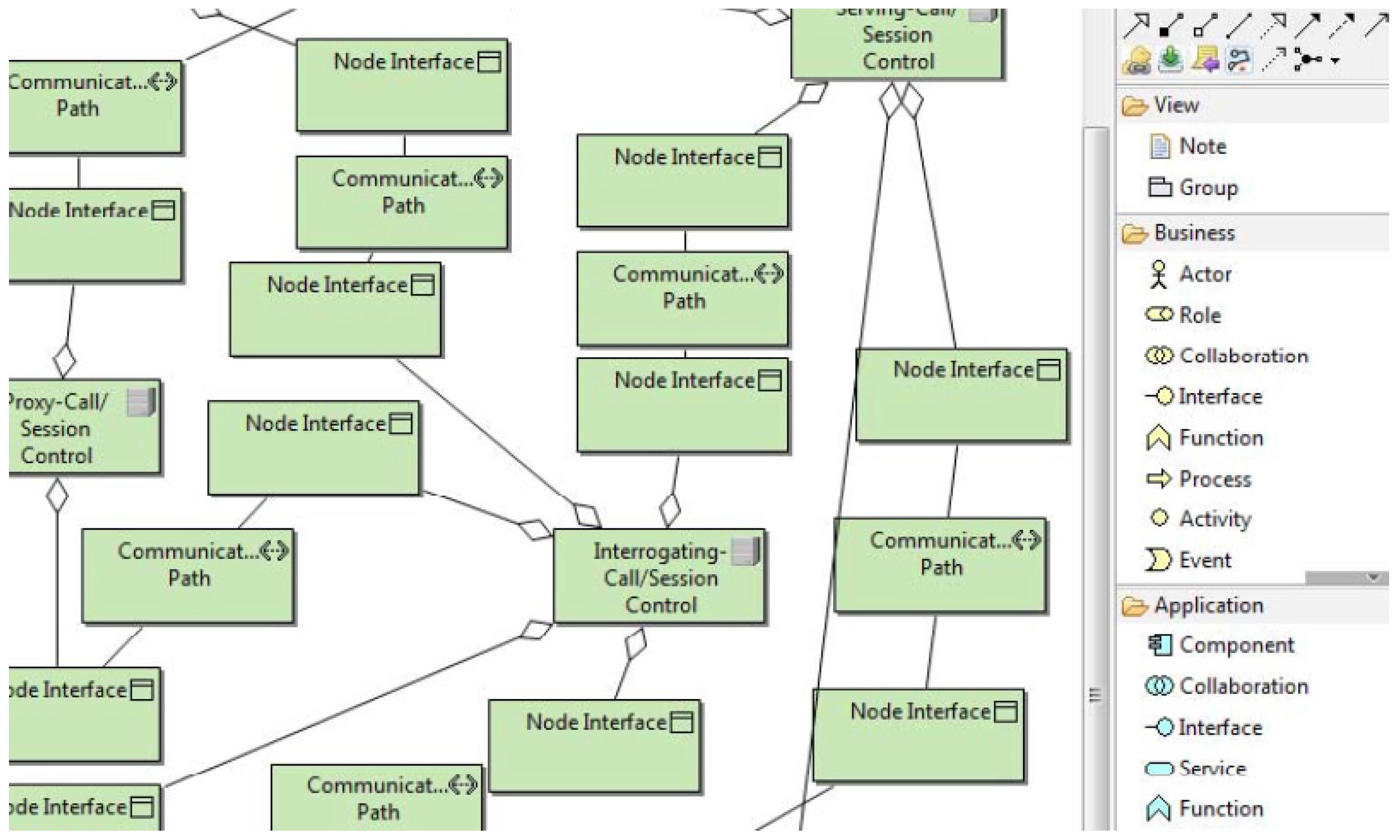
The topology and the tasks to be carried out in each of the network’s nodes are described in the technology model. We concentrate on the technological implementations of the InformA function from the application layer because of its extensive design. An extract from the extensive model (Figure 17) is showcased. To carry out the InformA application function, a wide range of technology functions such as SendTo are connected at the technology layer. A message of type SIP or Diameter can be forwarded or sent from one node to another via the SendTo function.
In the context of technology, we have extended the ArchiMO tool in [27] [22] by utilizing the IMS meta-model and ArchiMate. IMS standards are mostly considered and contained in this extension [57]. After the simulation program is executed, the NS-3 simulator creates animation script. The NetAnim tool imports this script to display the simulation scenario’s animation (Figure 18), which depicts the messages that are transmitted and received between the various nodes. The transparency of our model transformation methods is demonstrated by the produced topology and by watching the message exchanges between the various nodes.
6.4. Compilation and Simulation
An XMI file is generated using the enhanced ArchiMO design tool to reflect the graphical design. This facilitates the design model’s interaction with other tools.
The simulation code is generated by our own domain-specific model compiler using the XMI file as an input (Figure 13). This saves a significant amount of development time by concealing from the designer the complexity involved in building simulation programs.
For UEC, the code generator requires the input model generated by the ArchiMO design tool in addition to the meta-model containing the abstract syntax of DSML.
The mapping rules between the model elements and their representations in NS-3 are contained in the XPAND template in (Figure 13) [46]. The code is prone to errors, as evidenced by the compilation and execution results when we ran the resulting code in NS-3 (version 3.13). To analyze the results of the simulation, traces and logs (such as PCAP files) were created.
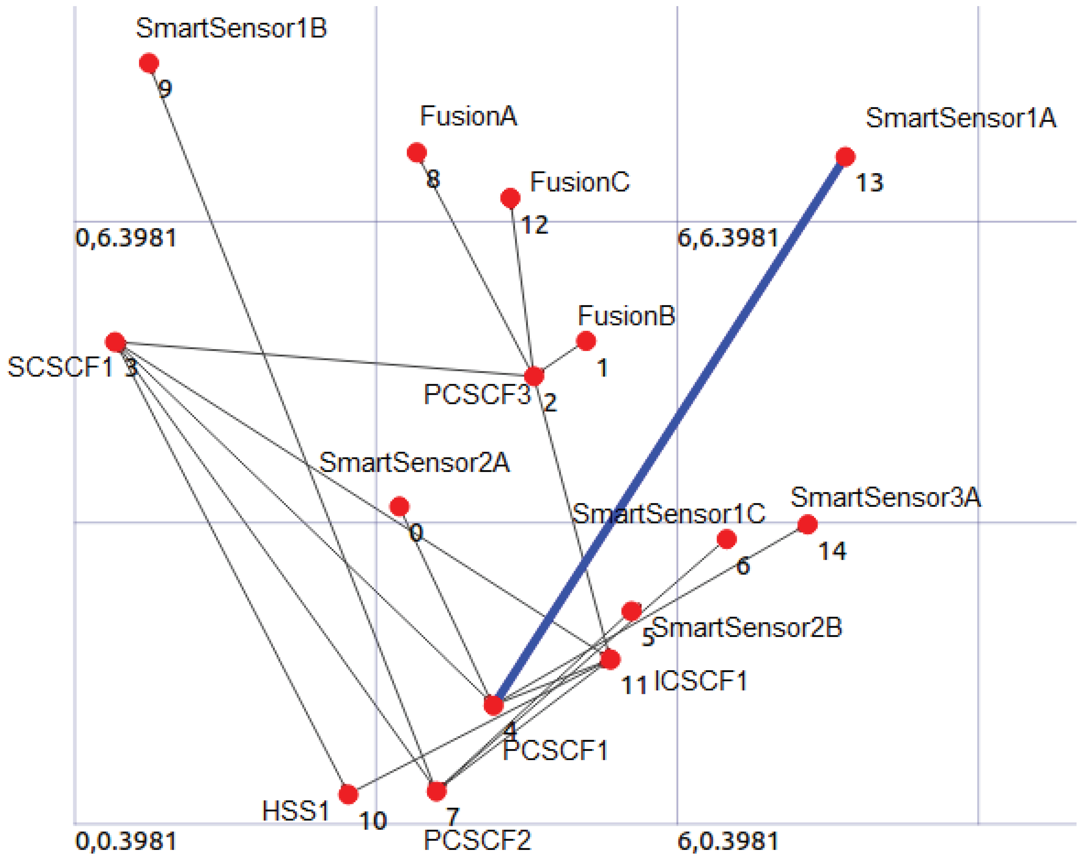
The architecture of the system design created by NS-3 for the specified design model is displayed in Figure 18. For each design model element, NS-3 produced a hardware representation (nodes, interfaces, and wires). A message that is transmitted and received at any given time between two nodes is represented by the blue stream. This attests to the behavioral aspects being mapped in the anticipated manner.
Our approach has been used to several application domains and network simulators (Video Conferencing System [45,46] and MO Context [16]). The underlying platform (IMS), which represents the Platform Specific Model (PSM), is the common design concept shared by all of these use cases [49].
Put differently, by addressing the underlying platform that is represented in the technology layer, we might modify the application domain while still relying on ArchiMate and our extensions (DSML) if we were to use a single tool (such as NS-3). This validates that the models generated by our extended design tool (ArchiMO) adhere to the same meta-model and domain-specific concepts/constraints.
In order to address the problem raised in Section 2, our testing approach does the following: (C5) give the designer the capacity to test and validate his model developed in MO on an executable platform that is part of the same framework in which the designer generates MO. This is achieved by first creating the model’s simulation code and then running it through NS-3.
7. Conclusion and Future Work
We have discussed and presented Underwater Environmental Constraints at a high abstract level in this study. These constraints are DSML extensions coupled with AI Database for the MO context.
We illustrated the proposed UEC and ArchiMO design tool, using a Marine Observatory case study. We presented a defined model for MO showing their different views: Business, Application, and Technology. These models are created with the help of our extended version of the ArchiMO design tool in terms of abstract syntax, concrete syntax, AI Database and semantics. This tool includes the newly proposed UEC based on MDE fundamentals. The system model is then validated by simulating the resulting consistent model with the NS-3 network simulator.
Our extended ArchiMO tool protects against design mistakes earlier than traditional design processes/activities and the code generation stage. We rely on a standard and open tool (Archi) that we extend through developing the modeling language and java implementations.
Another benefit of our proposed ArchiMO deign tool is its extensibility. Depending on the development of the SSN domain, the developers may extend it and add new (IIoT)/SSN concepts and constraints. Additionally, by incorporating new and recent useful data into the AI-Developed Database, which is one of the most popular and efficient ways to enhance the efficiency and precision of the AI learning control.
The additional UEC concepts and constraints can be reused in many applications, activities, models, or instances thanks to ArchiMO. Because ArchiMO’s palette includes specific concepts and constraints, it also shortens the time required for the design process. Additionally, we maintain the normative concepts and constraints in the abstract syntax (meta-model) of ArchiMate, since the recently added UEC inherit concepts from standard ArchiMate elements.
The opposite is also true: expressing, meta-modeling domain knowledge and enhancing the performance of AI learning control are challenging tasks that demand expertise and a high degree of accuracy, particularly when setting the DSML in accordance with the meta-model requirements and standards.
As perspectives, we will extend our ArchiMO meta-model and design tool by including new Intelligent Internet of Things (IIoT)/Smart Sensor Networks concepts, relationships, and UEC in order to satisfy and cover the most possible required operations, concepts and activities in the context of SSN and IIoT. In addition, we will expand the AI-Developed Database by adding more recent and useful data to it.
References
- Nayyar, A.; Ba, C.H.; Cong Duc, N.P.; Binh, H.D. Smart-IoUT 1.0: A smart aquatic monitoring network based on Internet of Underwater Things (IoUT). Industrial Networks and Intelligent Systems: 14th EAI International Conference, INISCOM 2018, Da Nang, Vietnam, August 27–28, 2018, Proceedings. Springer, 2019, pp. 191–207.
- Aoun, C.G.; Lagadec, L. An Extended Domain-Specific Modeling Language for Marine Observatory Relying on Enterprise Architecture. International Journal of Computer and Information Engineering 2023, 17, 564–572. [Google Scholar]
- Aoun, C.G.; Lagadec, L.; Habes, M. An extended modeling approach for marine/deep-sea observatory. International Conference on Advanced Machine Learning Technologies and Applications. Springer, 2022, pp. 502–514.
- Felemban, E.; Shaikh, F.K.; Qureshi, U.M.; Sheikh, A.A.; Qaisar, S.B. Underwater sensor network applications: A comprehensive survey. International Journal of Distributed Sensor Networks 2015, 11, 896832. [Google Scholar] [CrossRef]
- Fattah, S.; Gani, A.; Ahmedy, I.; Idris, M.Y.I.; Targio Hashem, I.A. A Survey on Underwater Wireless Sensor Networks: Requirements, Taxonomy, Recent Advances, and Open Research Challenges. Sensors 2020, 20. [Google Scholar] [CrossRef]
- Zhang, D.; Duan, X. Smart Sensors and Devices in Artificial Intelligence; MDPI, 2021.
- Li, G.; Zhou, X.; Cao, L. AI meets database: AI4DB and DB4AI. Proceedings of the 2021 International Conference on Management of Data, 2021, pp. 2859–2866.
- Liggins II, M.; Hall, D.; Llinas, J. Handbook of multisensor data fusion: theory and practice; CRC press, 2017. [Google Scholar]
- Marport. https://www.marport.com/.
- Awan, K.M.; Shah, P.A.; Iqbal, K.; Gillani, S.; Ahmad, W.; Nam, Y.; others. Underwater wireless sensor networks: A review of recent issues and challenges. Wireless Communications and Mobile Computing 2019, 2019.
- MeDON - Acoustic Data. URL: https://image.ifremer.fr/data/00754/86598/.
- Elsayed, W.; Elhoseny, M.; Sabbeh, S.; Riad, A. Self-maintenance model for wireless sensor networks. Computers & Electrical Engineering 2018, 70, 799–812. [Google Scholar]
- Islam, T.; Lee, Y.K. A comprehensive survey of recent routing protocols for underwater acoustic sensor networks. Sensors 2019, 19, 4256. [Google Scholar] [CrossRef] [PubMed]
- Coutinho, R.W.; Boukerche, A.; Vieira, L.F.; Loureiro, A.A. Underwater wireless sensor networks: A new challenge for topology control–based systems. ACM Computing Surveys (CSUR) 2018, 51, 1–36. [Google Scholar] [CrossRef]
- Chang, Y.C.; Li, J.W.; Lv, J.H. An IP Multimedia Subsystem Services Proxy Gateway Based on a JAVA Dynamic Module System. Applied Sciences 2018, 8, 2060. [Google Scholar] [CrossRef]
- Aoun, C. An enterprise architecture and model driven engineering based approach for sensor networks. PhD thesis, ENSTA Bretagne, 2018.
- Archi tool. http://https://www.archimatetool.com/.
- Casalaro, G.L.; Cattivera, G.; Ciccozzi, F.; Malavolta, I.; Wortmann, A.; Pelliccione, P. Model-driven engineering for mobile robotic systems: a systematic mapping study. Software and Systems Modeling 2022, 21, 19–49. [Google Scholar] [CrossRef]
- Aoun, C.; Alloush, I.; Kermarrec, Y.; Zein, O.; Champeau, J. Domain Specific Modeling Language for Object Localization in Marine Observatories. SENSORCOMM 2014 - 8th International Conference on Sensor Technologies and Applications 2014.
- Pérez-Castillo, R.; Delgado, A.; Ruiz, F.; Bacigalupe, V.; Piattini, M. A method for transforming knowledge discovery metamodel to ArchiMate models. Software And Systems Modeling 2022, pp. 1–26.
- Chiprianov, V.; Kermarrec, Y.; Rouvrais, S.; Simonin, J. Extending enterprise architecture modeling languages for domain specificity and collaboration: application to telecommunication service design. Software & Systems Modeling 2014, 13, 963–974. [Google Scholar]
- Alloush, I. A design and verification framework for telecommunication services. Theses, Télécom Bretagne ; Université de Bretagne Occidentale, 2016.
- Jazayeri, B.; Schwichtenberg, S.; Küster, J.; Zimmermann, O.; Engels, G. Modeling and Analyzing Architectural Diversity of Open Platforms. Advanced Information Systems Engineering; Dustdar, S.; Yu, E.; Salinesi, C.; Rieu, D.; Pant, V., Eds.; Springer International Publishing: Cham, 2020; pp. 36–53.
- Crnkovic, I.; Sentilles, S.; Feljan, A.; Chaudron, M. A Classification Framework for Software Component Models. Software Engineering, IEEE Transactions on 2011, 37, 593–615. [Google Scholar] [CrossRef]
- El Hachem, J.; Pang, Z.Y.; Chiprianov, V.; Babar, A.; Aniorte, P. Model Driven Software Security Architecture of Systems-of-Systems. 2016 23rd Asia-Pacific Software Engineering Conference (APSEC), 2016, pp. 89–96. [CrossRef]
- Medvidovic, N.; Taylor, R. A classification and comparison framework for software architecture description languages. 1 Jan 2000, 26, 70–93.
- Chiprianov, V. Collaborative Construction of Telecommunications Services. An Enterprise Architecture and Model Driven Engineering Method. PhD thesis, Telecom Bretagne, France, 2012.
- Touraille, L.; Traoré, M.K.; Hill, D.R.C. A model-driven software environment for modeling, simulation and analysis of complex systems. Proceedings of the 2011 Symposium on Theory of Modeling & Simulation: DEVS Integrative M&S Symposium; , 2011; TMS-DEVS ’11, pp. 229–237.
- A. Achilleos, K.Y.; Georgalas, N. Context modelling and a context-aware framework for pervasive service creation: A model-driven approach. Pervasive and Mobile Computing 2010, 6, 281–296. [CrossRef]
- Bakker, J.L.; Jain, R. Next generation service creation using XML scripting languages 2002. 4, 2001–2007 vol.4. [CrossRef]
- NATO Architecture Framework, Version 4, 31 Aug. 2022. https://www.nato.int/cps/en/natohq/topics_157575.htm.
- Chiprianov, V.; Alloush, I.; Kermarrec, Y.; Rouvrais, S. Telecommunications Service Creation: Towards Extensions for Enterprise Architecture Modeling Languages. 6th Intl. Conf. on Software and Data Technologies (ICSOFT); , 2011; Vol. 1, pp. 23–29.
- Chiprianov, V.; Kermarrec, Y.; Rouvrais, S. Extending Enterprise Architecture Modeling Languages: Application to Telecommunications Service Creation. The 27th Symposium On Applied Computing; ACM: Trento, 2012; pp. 21–24.
- Brumbulli, M.; Gaudin, E.; Teodorov, C. Automatic Verification of BPMN Models. 10th European Congress on Embedded Real Time Software and Systems (ERTS 2020); , 2020.
- Sabu, D.; Alagumariappan, P.; Sankaran, V.; Pittu, P.S.K.R. Design and Development of Internet of Things-Based Smart Sensors for Monitoring Agricultural Lands. Engineering Proceedings 2023, 58, 13. [Google Scholar]
- Sorribas, J.; del Río, J.; Trullols, E.; Manuel, A. A smart sensor architecture for marine sensor networks. International conference on Networking and Services (ICNS’06). IEEE, 2006, pp. 93–93.
- Božić, V. Applications of fog computing for smart sensors.
- Sorribas, J.; Barba, A.; Trullols, E.; Del Rio, J.; Manuel, A.; de la Muela, M. Marine Sensor Networks and Ocean Observatories. A Policy Based Management Approach. Computing in the Global Information Technology, 2008. ICCGI ’08. The Third International Multi-Conference on, 2008, pp. 143–147. [CrossRef]
- NEPTUNE - Ocean Networks Canada. https://www.oceannetworks.ca/.
- Saheban, H.; Kordrostami, Z. Hydrophones, fundamental features, design considerations, and various structures: A review. Sensors and Actuators A: Physical 2021, 329, 112790. [Google Scholar] [CrossRef]
- Pérez-Medina, J.L.; Dupuy-Chessa, S.; Front, A. A Survey of Model Driven Engineering Tools for User Interface Design. Proceedings of the 6th International Conference on Task Models and Diagrams for User Interface Design; Springer-Verlag: Berlin, Heidelberg, 2007; TAMODIA’07, pp. 84–97.
- Bezivin, J. In search of a basic principle for model driven engineering,. Novatica Journal 2004, vol. 2, pp. 21–24.
- Atlas transformation language. http://www.eclipse.org/atl/.
- Eclispe Modeling. http://www.eclipse.org/modeling/.
- Alloush, I.; Chiprianov, V.; Kermarrec, Y.; Rouvrais, S. Linking Telecom Service High-Level Abstract Models to Simulators Based on Model Transformations: The IMS Case Study. Information and Communication Technologies (EUNICE 2012); Szabó, R.; Vidócs, A., Eds. Springer Berlin Heidelberg, 2012, Vol. 7479, Lecture Notes in Computer Science, pp. 100–111.
- Alloush, I.; Kermarrec, Y.; Rouvrais, S. A generalized model transformation approach to link design models to network simulators: NS-3 case study. International Conference on Simulation and Modeling Methodologies, Technologies and Applications (SIMULTECH 2013). SciTePress Digital Library, 2013, pp. 337–344. [CrossRef]
- Zekai Demirezen, Barrett R. Bryant, M.M.T. DSML Design Space Analysis. UAB, Birmingham, AL 35294, USA, 2011.
- Cho, H.; Gray, J.; Syriani, E. Creating visual Domain-Specific Modeling Languages from end-user demonstration. Modeling in Software Engineering (MISE), 2012 ICSE Workshop on, 2012, pp. 22–28. [CrossRef]
- Kurtev, I.; Bézivin, J.; Jouault, F.; Valduriez, P. Model-based DSL frameworks. Companion to the 21st ACM SIGPLAN symposium on Object-oriented programming systems, languages, and applications; ACM: New York, NY, USA, 2006; OOPSLA ’06, pp. 602–616.
- Sommerville, I. Sofware Engineering, Ninth Edition; Pearson, 2011.
- Quartel, D.; Engelsmanb, W.; Jonkersb, H.; van Sinderenc, M. A goal-oriented requirements modelling language for enterprise architecture. Enterprise Distributed Object Computing Conference, 2009. EDOC ’09. IEEE International. University of Twente, IEEE, 2009, pp. 3 – 13. [CrossRef]
- Durrant-Whyte, H.; Stevens, M. Data Fusion in Decentralised Sensing Networks, Australian Centre for Field Robotics, The University of Sydney. NSW 2006.
- Zeigler, B. Theory of Modeling and Simulation. Academic Press google schola 2000, 2, 1779–1785. [Google Scholar]
- Aoun, C.G.; Alloush, I.; kermarrec, Y.; Champeau, J.; Zein, O.K. A mapping approach for Marine Observatory relying on enterprise architecture. OCEANS 2015 - MTS/IEEE Washington, 2015, pp. 1–10. [CrossRef]
- Aoun, C.; Alloush, I.; Kermarrec, Y.; Champeau, J.; Zein, O. A Modeling Approach for Marine Observatory. Sensors & Transducers 2015, 185. [Google Scholar]
- Aoun, C.; Lagadec, L.; Champeau, J.; Moussa, J.; Hanna, E. A High Abstraction Level Constraint for Object Localization in Marine Observatories. 2017, pp. 605–611. [CrossRef]
- Camarillo, G.; Garcia-Martin, M.A. The 3G IP multimedia subsystem (IMS): merging the Internet and the cellular worlds; John Wiley & Sons, 2007. [Google Scholar]
| 1 | viewpoint: is a work product establishing the conventions for the construction, interpretation and use of architecture views to frame specific system concerns |
| 2 | The meta-model defines by itself a language for describing a Specific Domain of interest [41] |
Figure 1.
Centralized and Distributed Fusion Architecture [8]
Figure 1.
Centralized and Distributed Fusion Architecture [8]
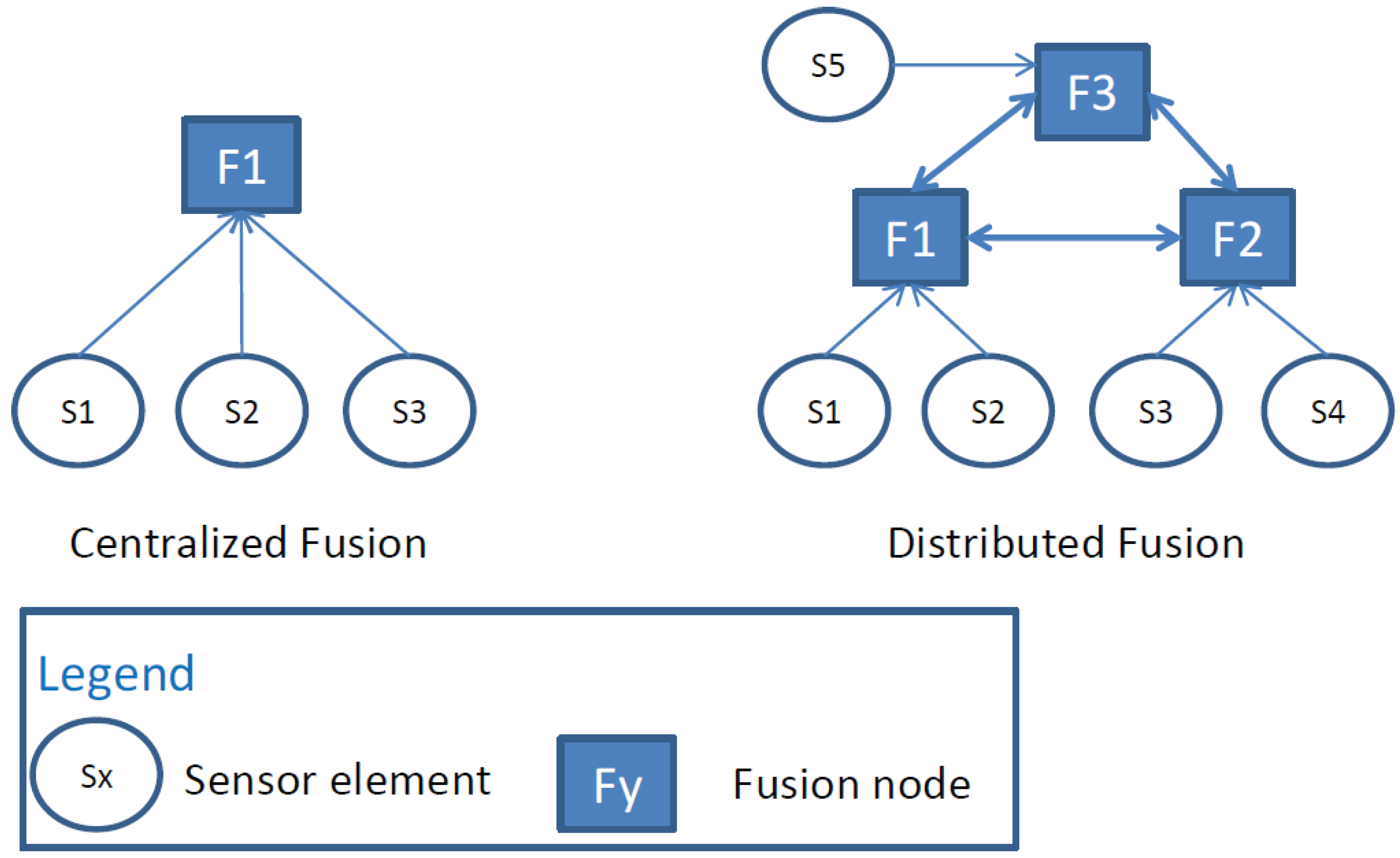
Figure 2.
MeDON’s run-time (Based on Distributed Fusion Architecture (Figure 1) - An example: N = 6 Smart Sensors and Y = 3 Smart Fusions Servers)
Figure 2.
MeDON’s run-time (Based on Distributed Fusion Architecture (Figure 1) - An example: N = 6 Smart Sensors and Y = 3 Smart Fusions Servers)

Figure 3.
ArchiMO Meta-Model - Extended Business and Application layers of Archimate
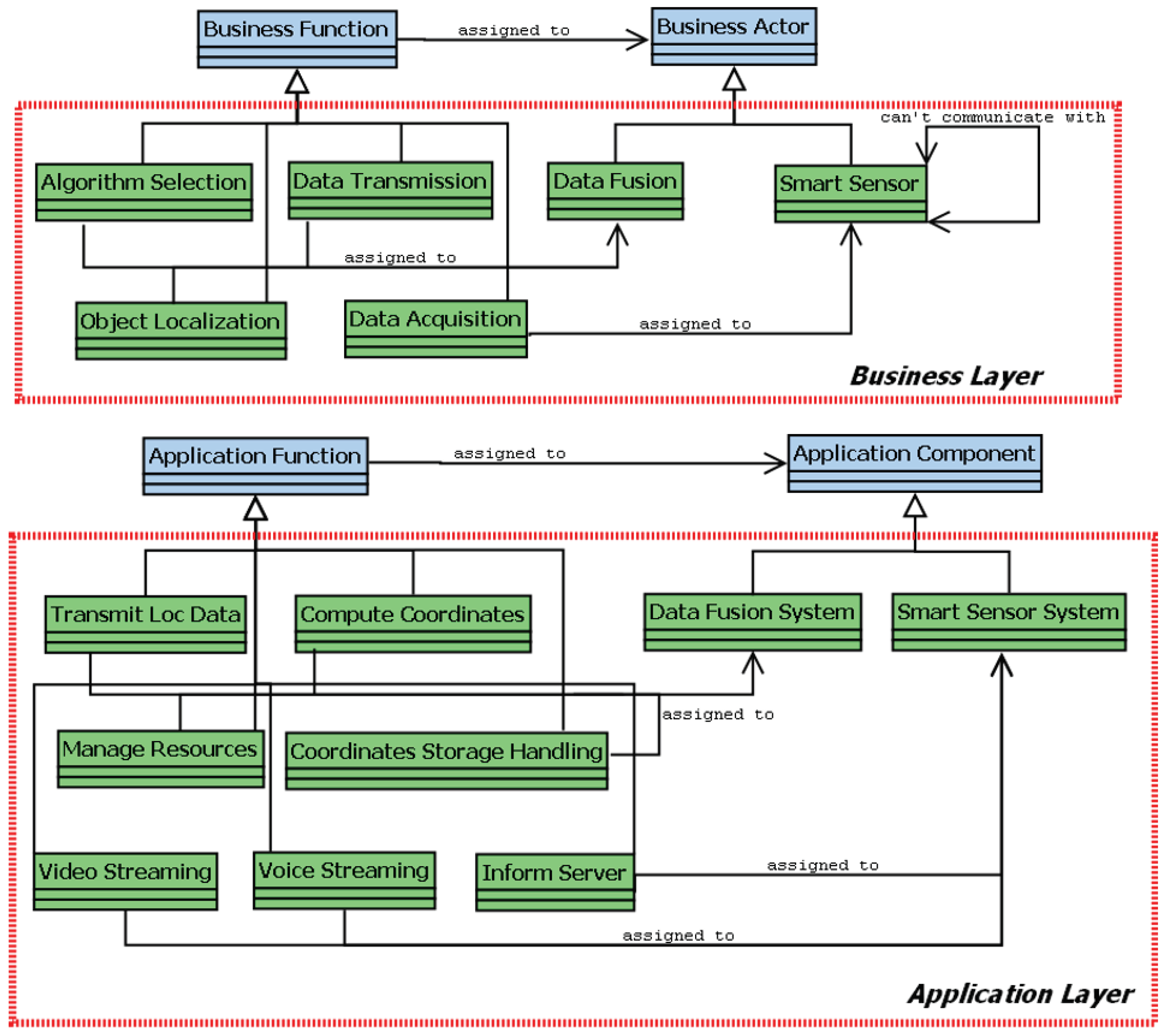
Figure 4.
ArchiMO Design Tool - Extended MO Business and Application Layers (Palettes) [19]
Figure 4.
ArchiMO Design Tool - Extended MO Business and Application Layers (Palettes) [19]
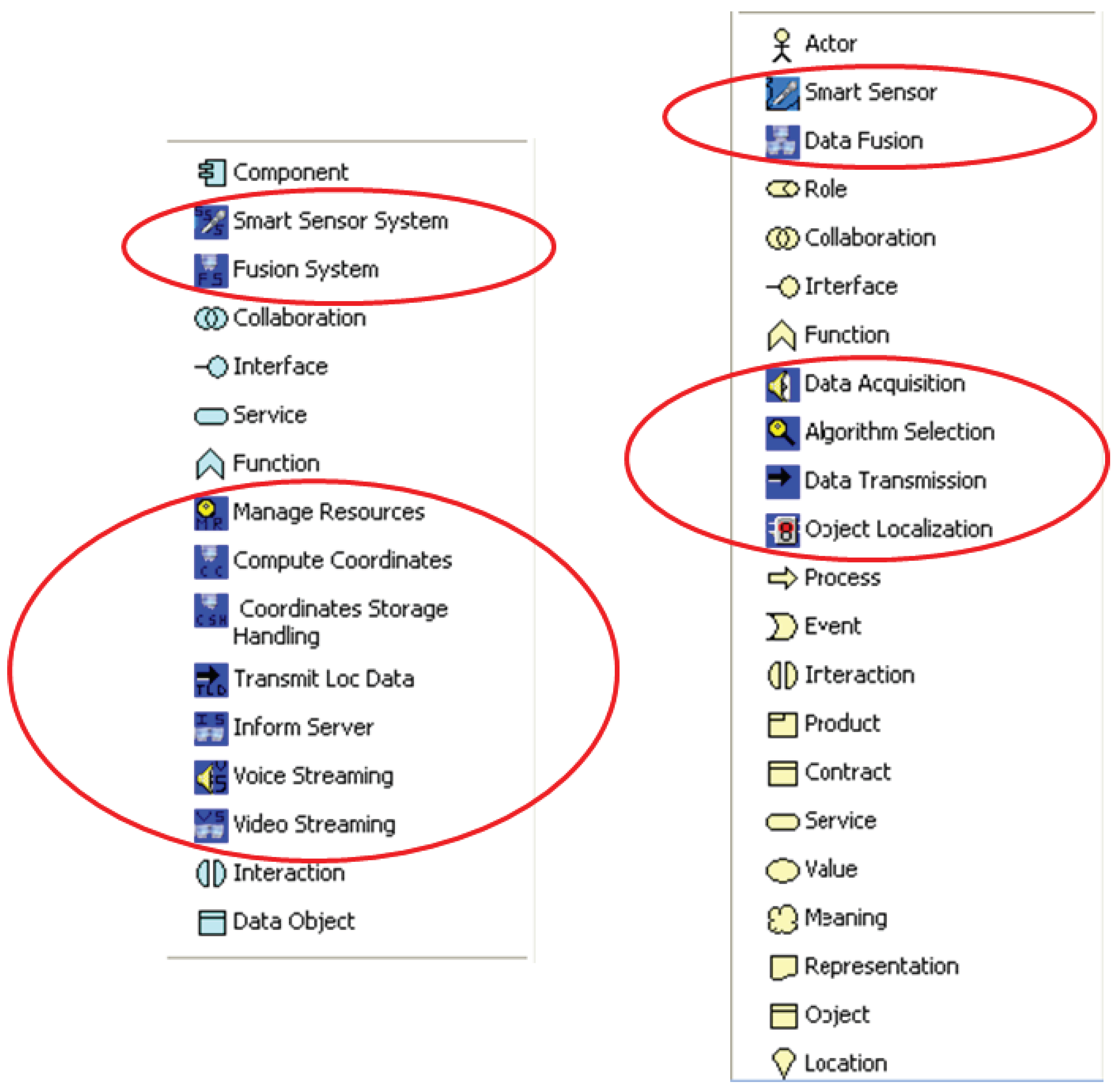
Figure 5.
Smart Sensor Architecture for Marine Sensor Networks (MSN). Orange and yellow boxes are hardware nodes while blue ones are software nodes. White rectangular shapes with two “tails” are software components [36].
Figure 5.
Smart Sensor Architecture for Marine Sensor Networks (MSN). Orange and yellow boxes are hardware nodes while blue ones are software nodes. White rectangular shapes with two “tails” are software components [36].
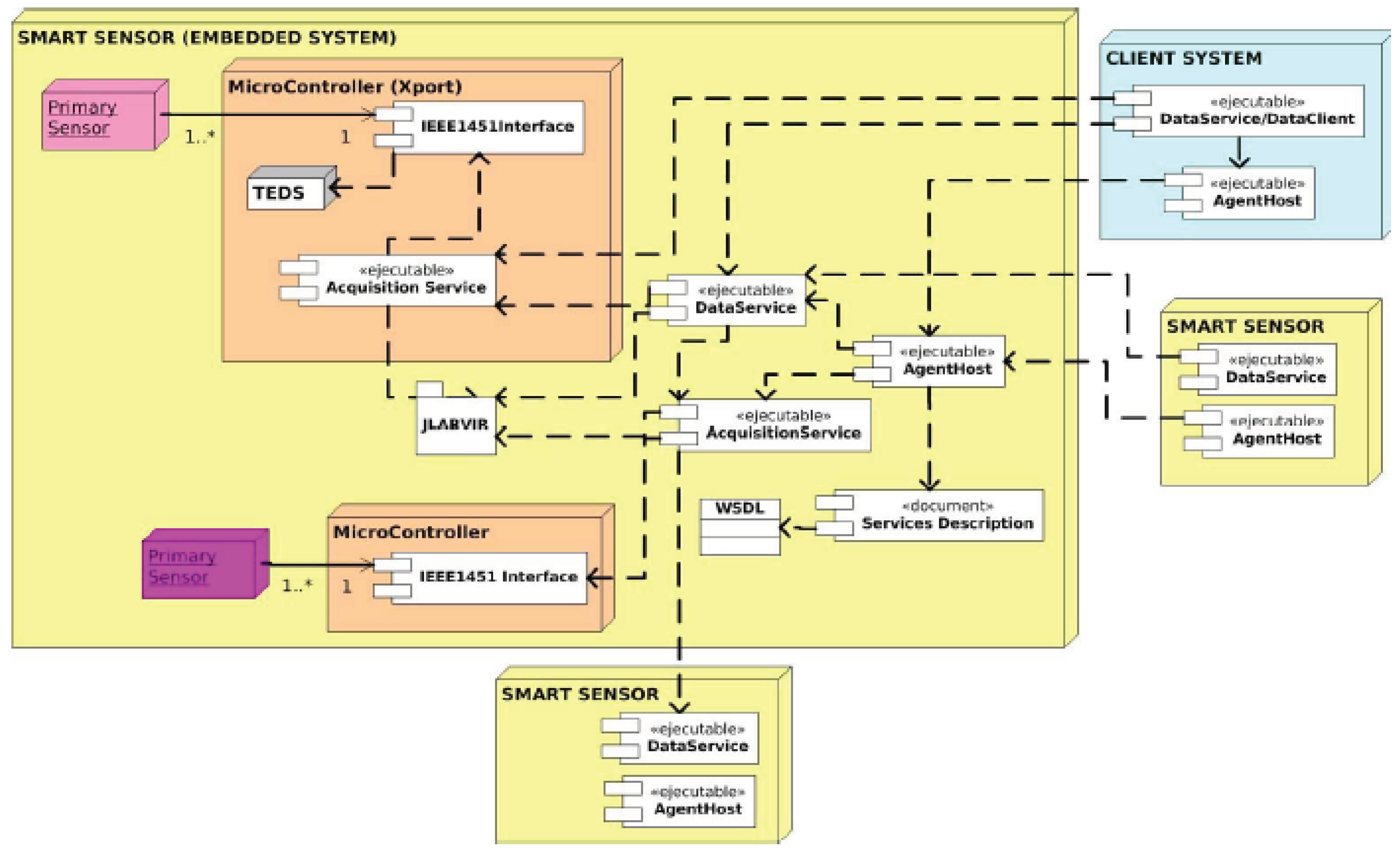
Figure 6.
Structure of the distributed software of the Information System of MeDON
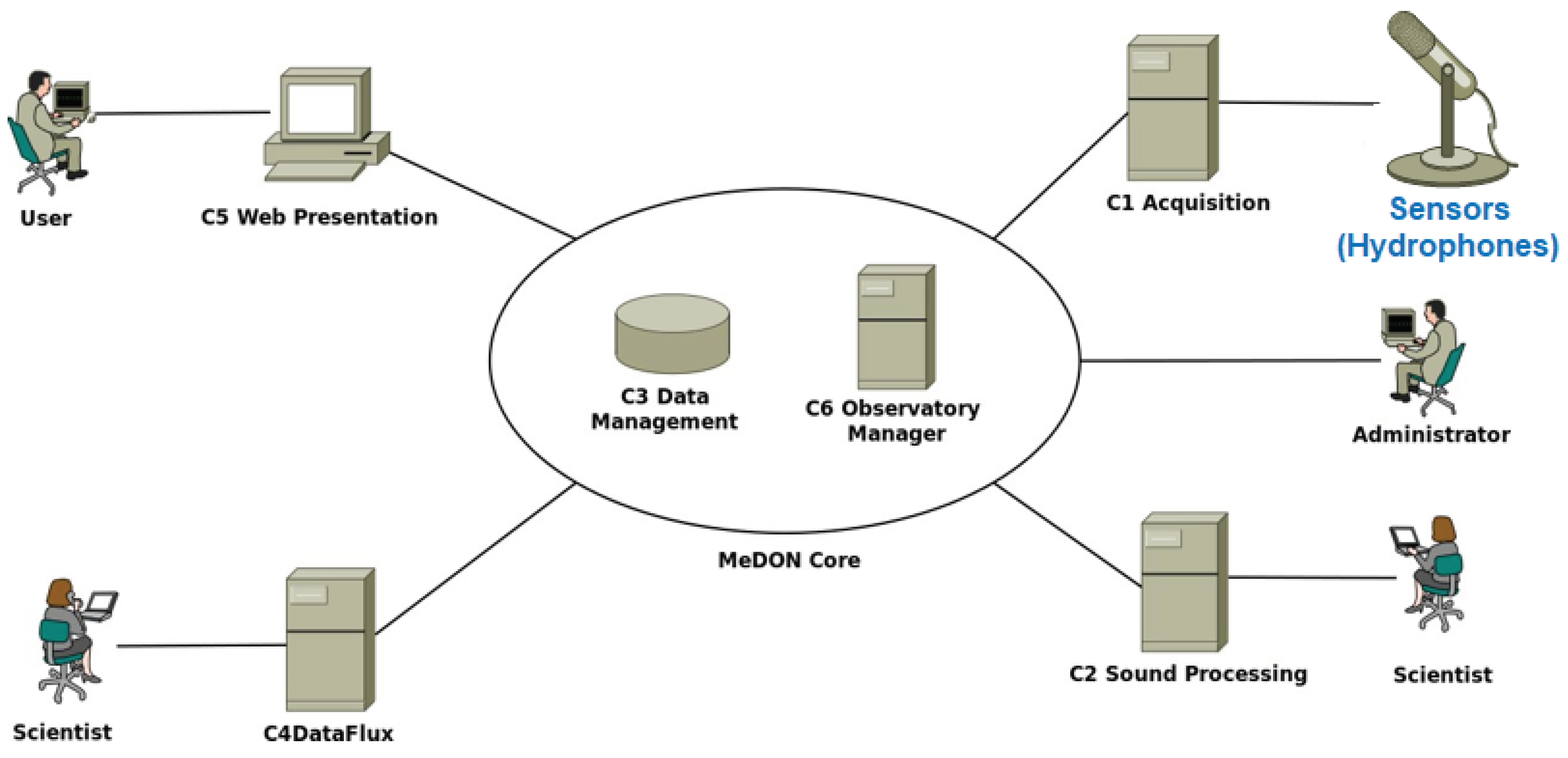
Figure 7.
Physical deployment of the Information System of MeDON
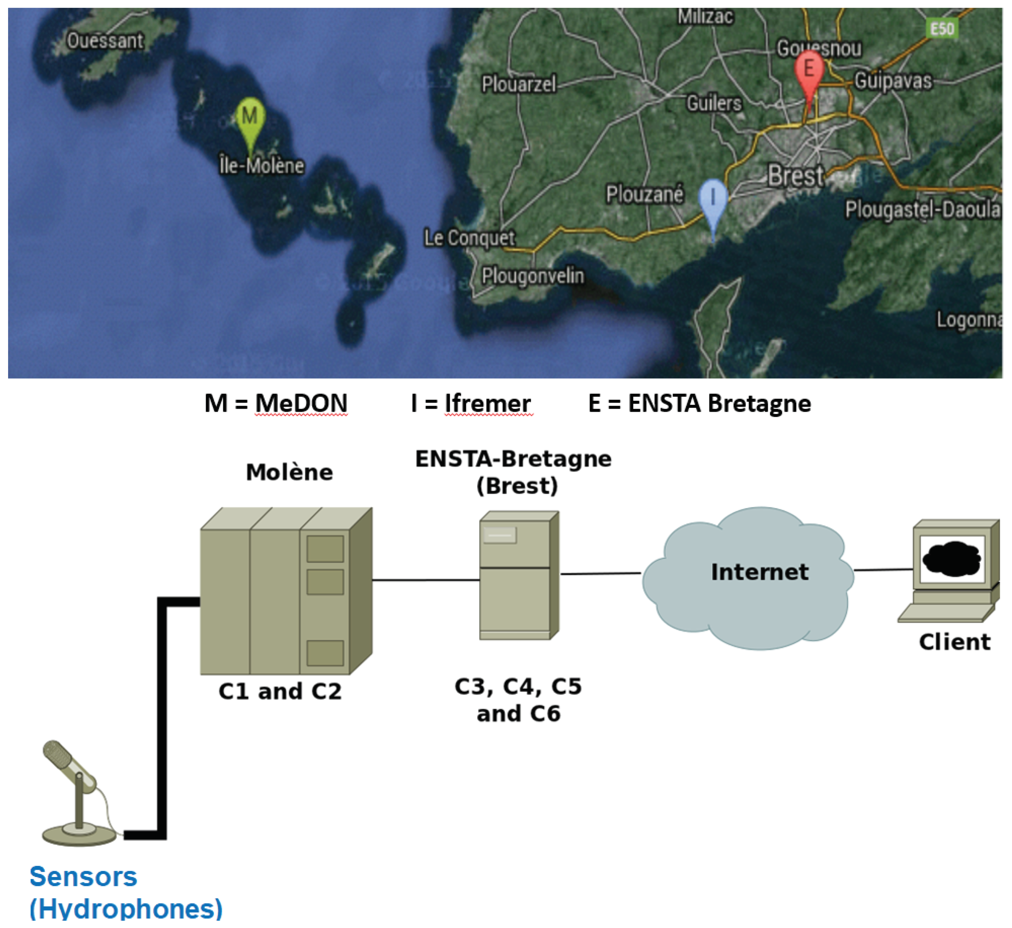
Figure 8.
Aspects of hydrophones [40]
Figure 8.
Aspects of hydrophones [40]
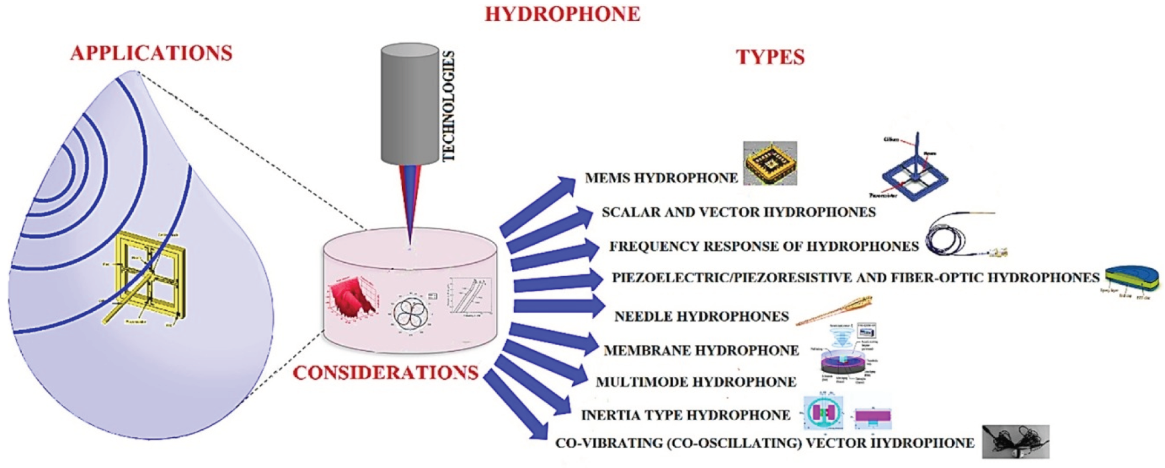
Figure 9.
Logical Activities of MO/MeDON
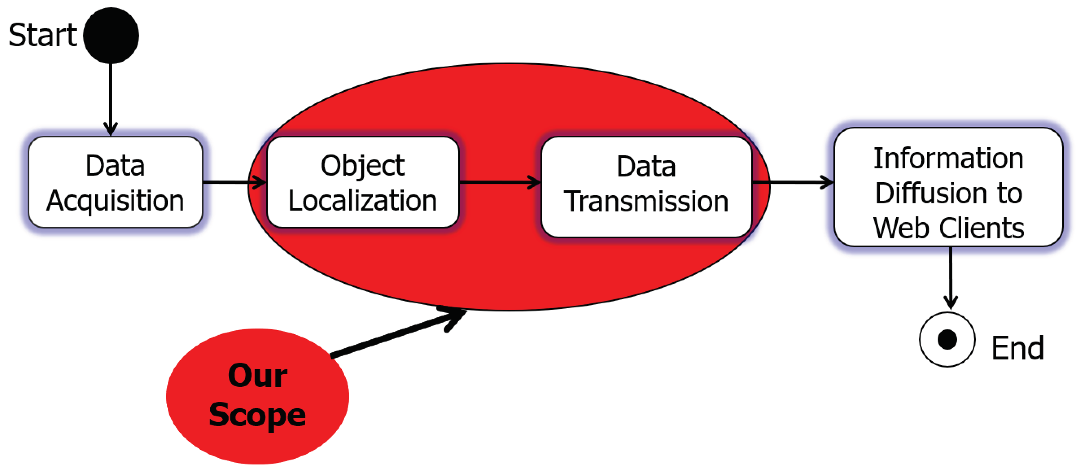
Figure 10.
Operational AI Database Model - Underwater Environmental Constraints
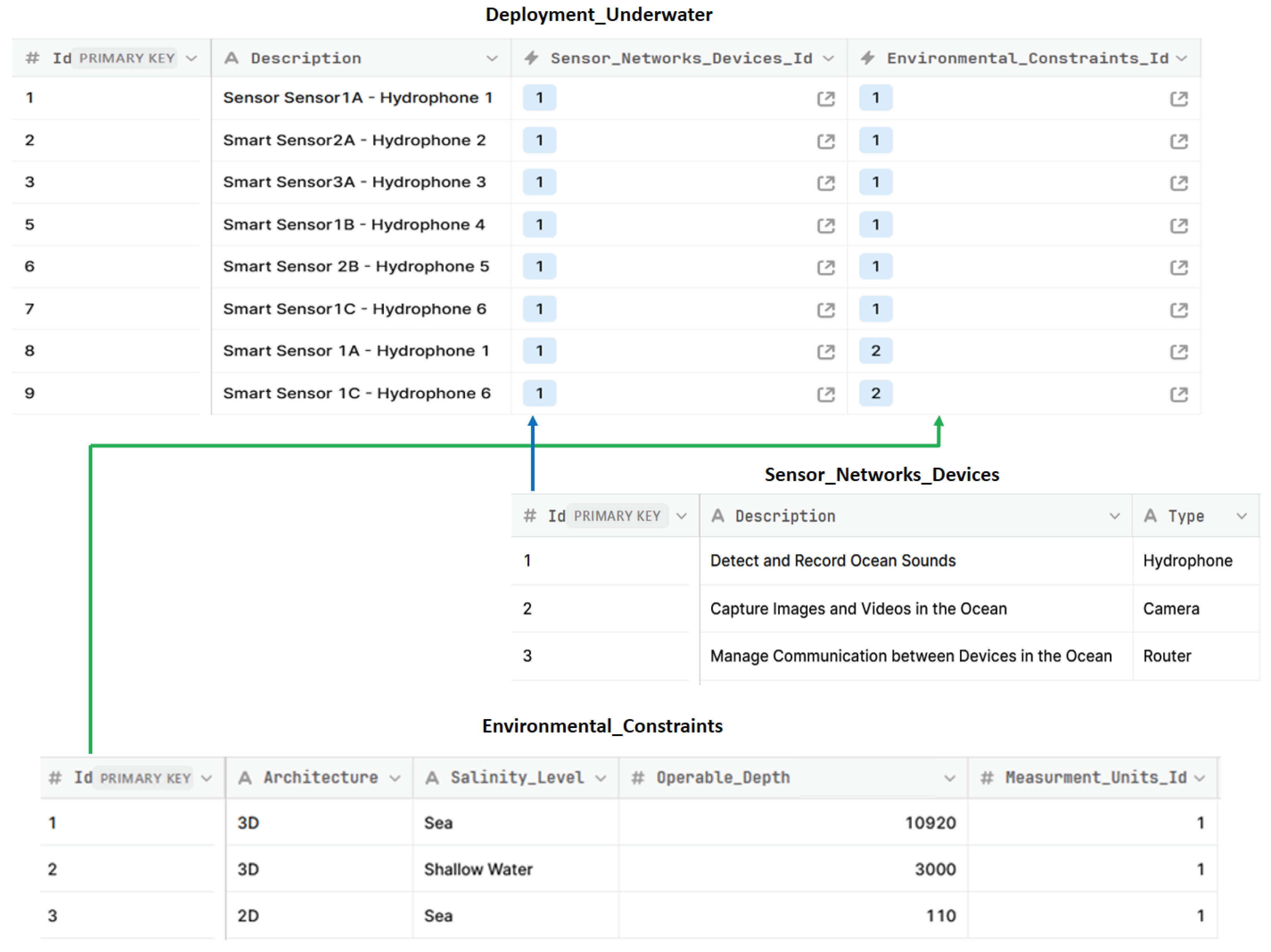
Figure 11.
Appropriate Underwater Environmental Constraints
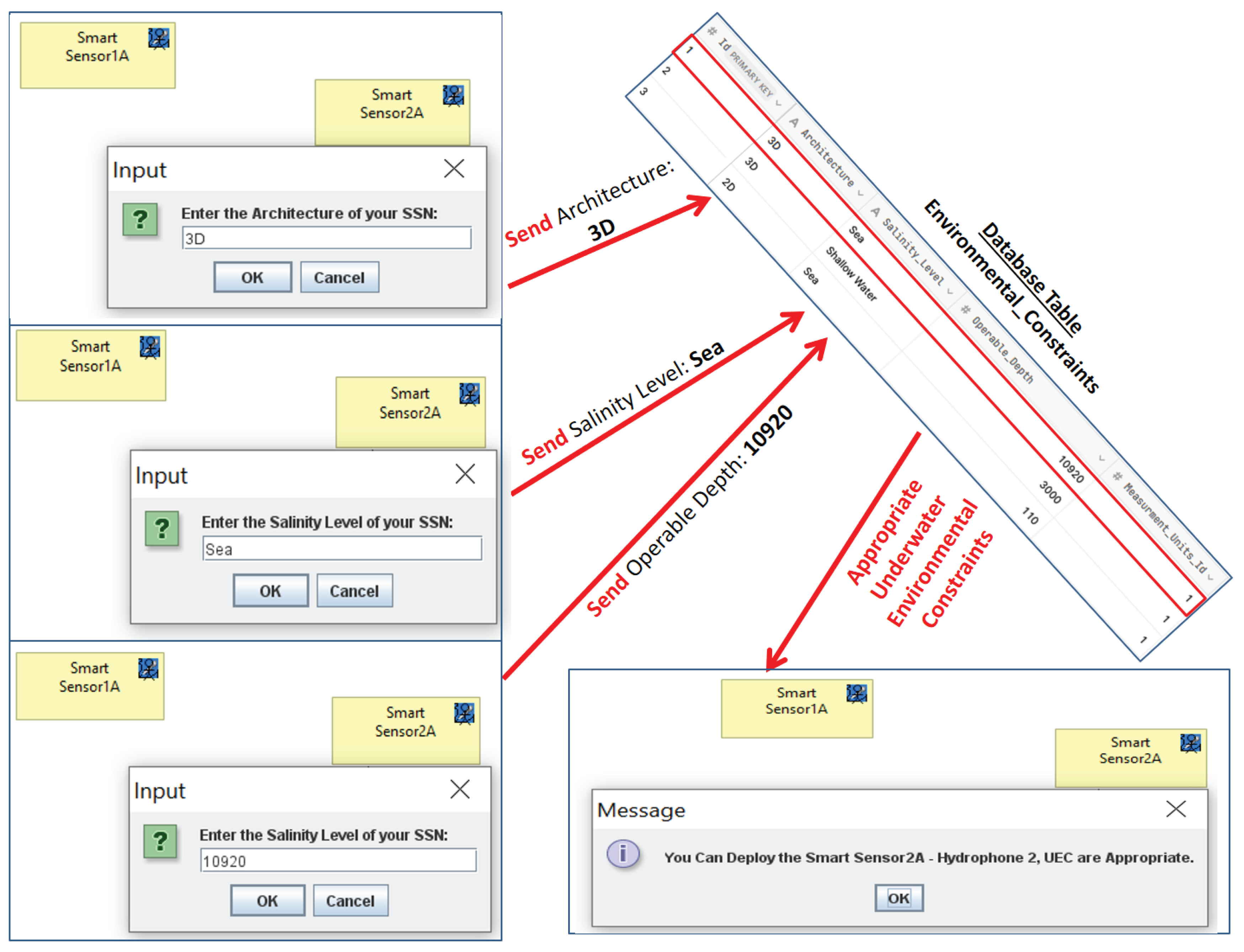
Figure 12.
Inappropriate Underwater Environmental Constraints
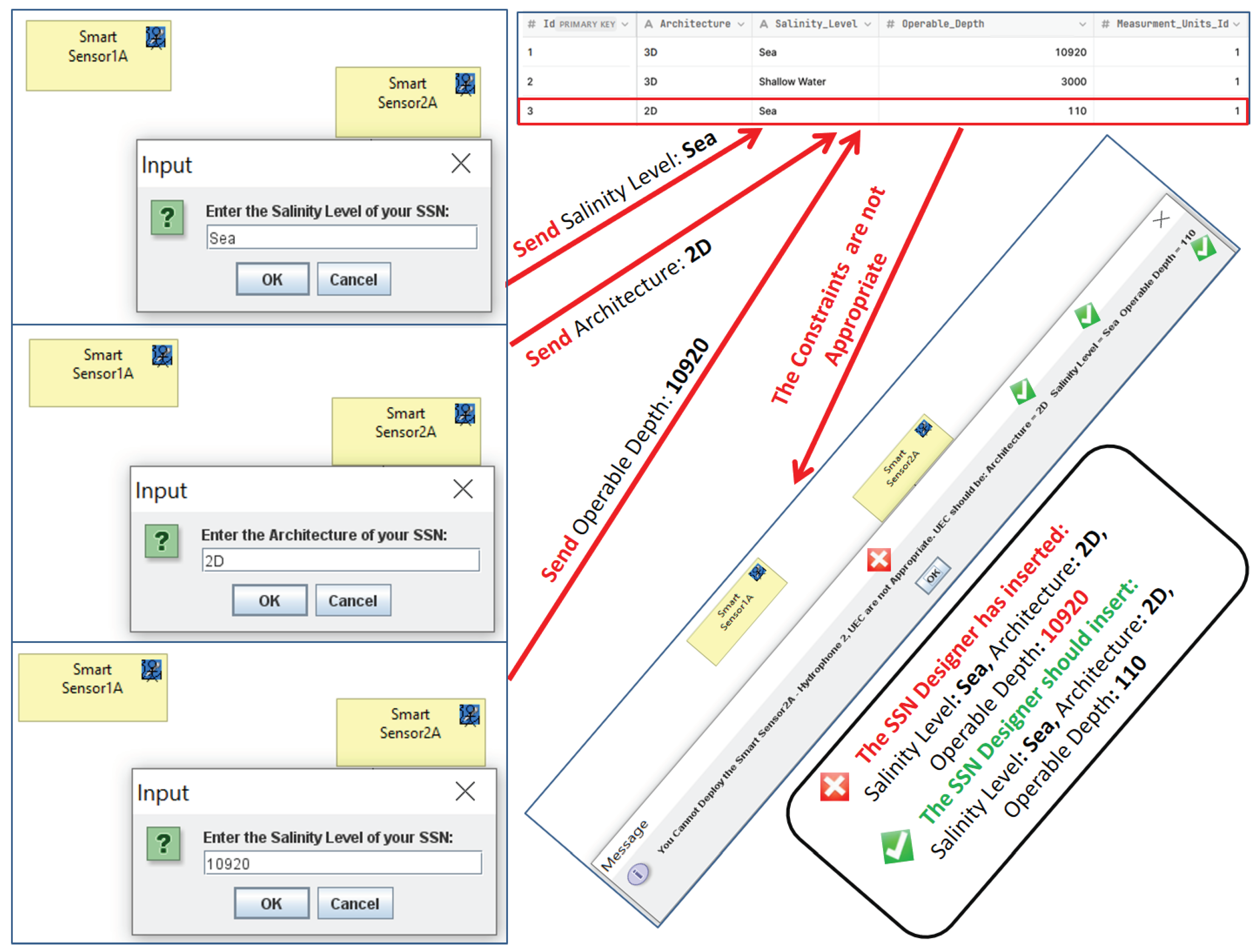
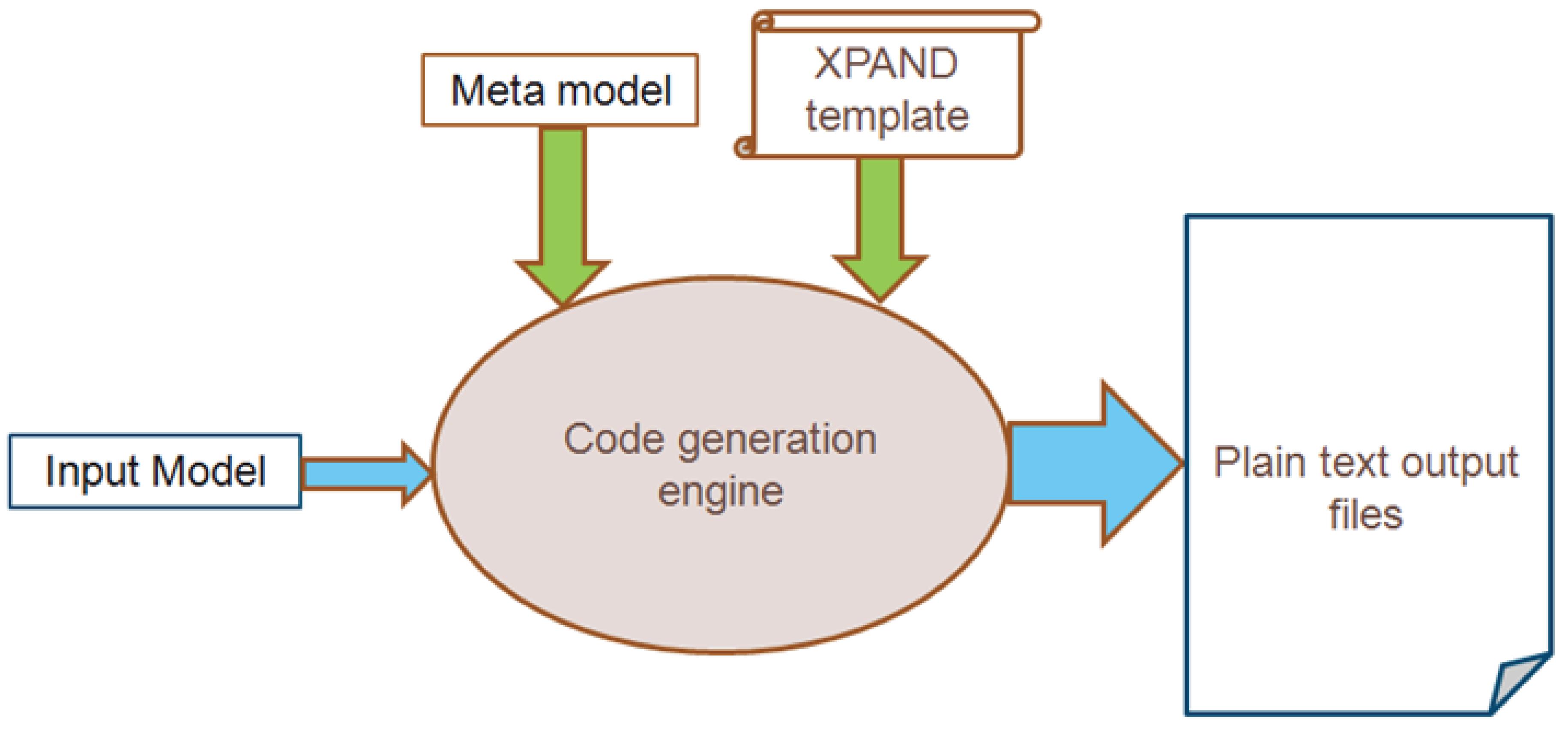
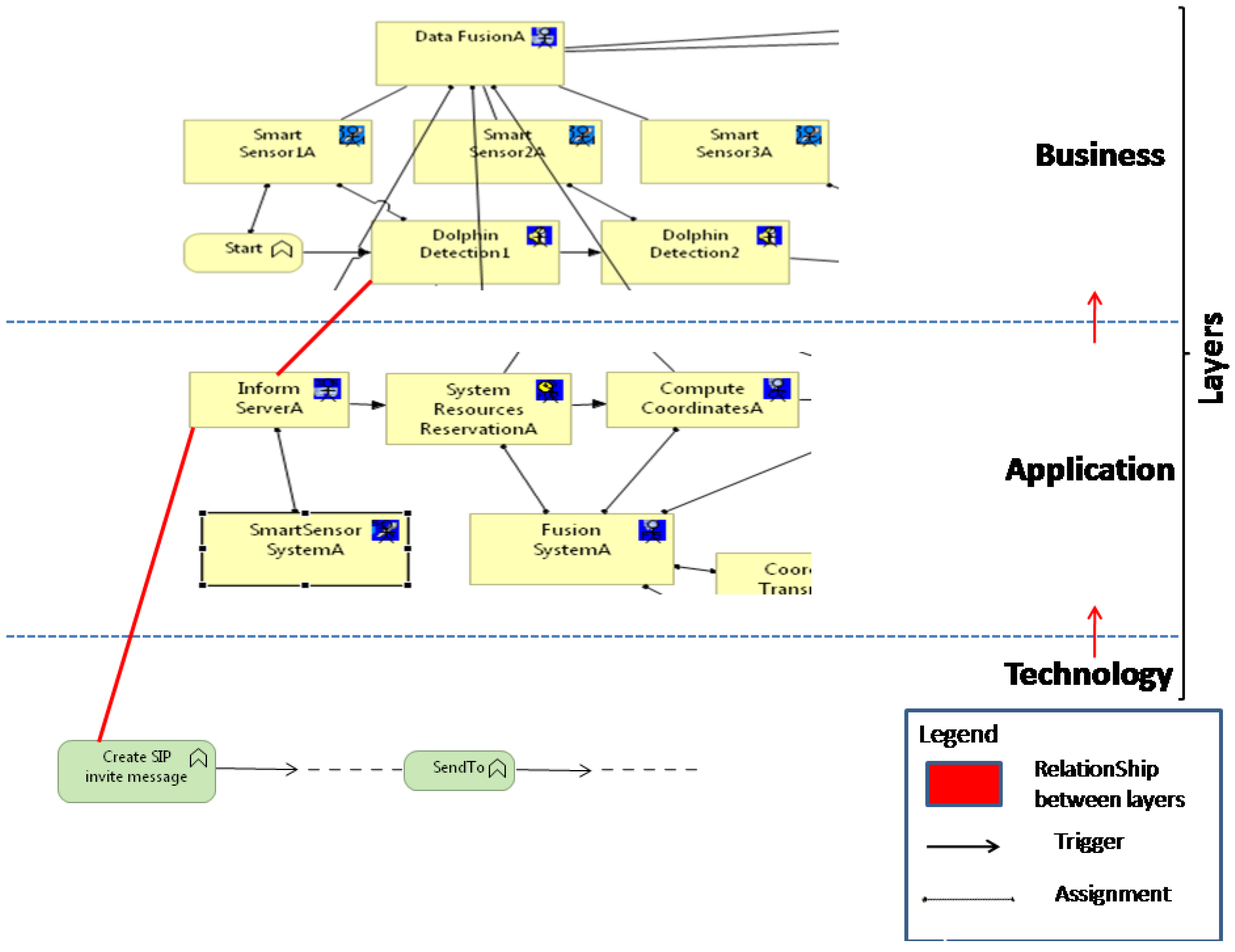
Figure 15.
Business view from the underwater object (dolphin) localization model [16] - ArchiMate Business Layer
Figure 15.
Business view from the underwater object (dolphin) localization model [16] - ArchiMate Business Layer
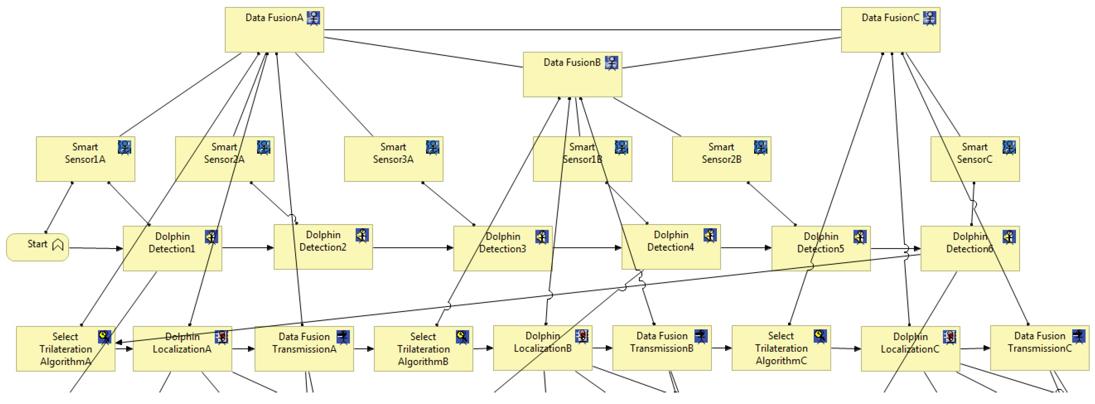
Figure 16.
Application view from the underwater object (dolphin) localization model [16] - ArchiMate Application Layer
Figure 16.
Application view from the underwater object (dolphin) localization model [16] - ArchiMate Application Layer
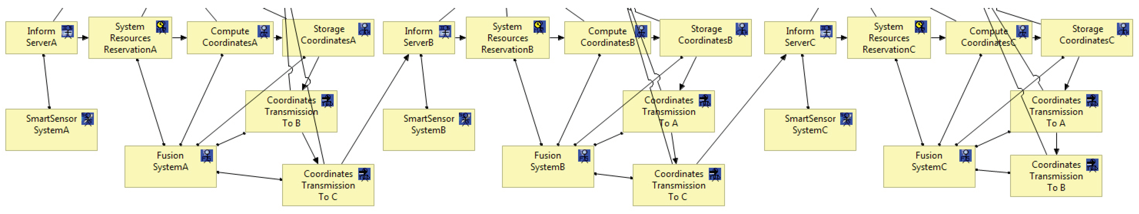
Figure 17.
An excerpt of the technology view from the underwater object (dolphin) localization model [16,22] - ArchiMate Technology Layer
Disclaimer/Publisher’s Note: The statements, opinions and data contained in all publications are solely those of the individual author(s) and contributor(s) and not of MDPI and/or the editor(s). MDPI and/or the editor(s) disclaim responsibility for any injury to people or property resulting from any ideas, methods, instructions or products referred to in the content. |
© 2024 by the authors. Licensee MDPI, Basel, Switzerland. This article is an open access article distributed under the terms and conditions of the Creative Commons Attribution (CC BY) license (http://creativecommons.org/licenses/by/4.0/).
Copyright: This open access article is published under a Creative Commons CC BY 4.0 license, which permit the free download, distribution, and reuse, provided that the author and preprint are cited in any reuse.
Submitted:
04 March 2024
Posted:
05 March 2024
You are already at the latest version
Alerts
A peer-reviewed article of this preprint also exists.
This version is not peer-reviewed
Submitted:
04 March 2024
Posted:
05 March 2024
You are already at the latest version
Alerts
Abstract
Through the use of Smart Sensor Networks (SSN), Marine Observatories (MO) provide continuous ocean monitoring. Deployed sensors may not perform as intended due to the heterogeneity of SSN devices’ hardware and software when combined with the Internet. Hence, SSN are regarded as complex distributed systems. As such, SSN designers will encounter challenges throughout the design phase related to time, complexity, sharing diverse domain experiences (viewpoints), and ensuring optimal performance for the deployed SSN. To this end, we describe in this article how we extended our previously proposed ArchiMO meta-model and design tool by extending an Enterprise Architecture Framework based on the ArchiMate Modeling Language. This extension proposes the incorporation of new Underwater Environmental Constraints (UEC) for SSN in ArchiMO which is coupled with the fusion of sensors with Artificial Intelligence. This serves as the basis for generating a new version of our ArchiMO design tool, which incorporates the new added constraints and invokes the AI created Database. To illustrate our proposal, we use the newly generated ArchiMO to create a model in the MO domain. Furthermore, we use our self-developed domain-specific model compiler to produce the relevant simulation code. Throughout the design phase, our approach contributes to handle and control the uncertainties and variances of the provided quality of service that may occur during the performance of the SSN, hence reducing the design activity’s complexity and time. It provides a way to share the different viewpoints of the designers in the domain of SSN.
Keywords:
Subject: Computer Science and Mathematics - Computer Science
1. Introduction
Intelligent Internet of Underwater Things (IIoUT) is proposed for sensing, collecting and storing underwater information [1]. IIoUT is an application based on Underwater Smart Sensor Networks (USSN) since it enhances deep sea monitoring, tracking various aquatic creatures, and ocean monitoring and observation systems, which are based on acoustic communication [2,3]. Logically, (USSN) operates in the same manner as the Smart Sensor Networks (SSN) that is not submerged in water, providing the same services, such as Deep Sea/Underwater monitoring. The USSN deployment phase, however, differs from the non-underwater phase in that experts must consider certain underwater environmental constraints during this phase. Failure to do so could have a negative impact on the performance of the entire SSN and result in improper underwater deployment of all SSN components, including servers, sensors, cables, and other physical and telecommunication components [4,5].
Smart Sensor Networks (SSN) is composed of artificial intelligence (AI) and several specialized sensors [6]. This demonstrates how Smart Sensors are connected to various Smart Fusion Servers with AI Databases [7] through the use of Distributed Fusion Architecture (Figure 1) [8] to carry out multiple tasks like collecting, processing, and storing data continuously and permanently from various sensors dispersed throughout various locations within the same network. Therefore, the primary job of SSN is to gather environmental data and transmit it to a centralized location or processing system, such a Smart Fusion Server, for evaluation and decision-making. By now, it ought to be obvious how challenging it is to create USSN since various resources contribute to its intricacy. Nonetheless, in this article, we specifically discuss the following [5,9,10]: since a distributed system’s architecture consists of many heterogeneous components, it is a complicated system by itself. This indicates that it will be challenging to analyze, design and deploy USSN. Certainly, you can expand upon the importance of the design of the USSN and the potential consequences of design mistakes throughout the deployment phase of any USSN project. This is due to the fact that, in the USSN life cycle, the design phase is performed first, coming before the deployment phase.
We focus our research on the applications for the Marine Observatories (MO) which have a common concept but employ diverse technologies. More specifically, our research’s focus is dedicated on the Marine e-Data Observatory Network (MeDON)(Figure 2).
The MeDON project [11] relies on USSN in order to enable continuous ocean observation. MeDON uses various communication protocols (REST, SOAP, and executive ones) to connect its various physical and logical components (e.g., Smart Sensors, Smart Fusion Servers, and Object Localization Algorithms) and together, these sensors gather data, which is subsequently transferred to the assigned workstations where it operates as a complex distributed information system. This indicates that the structure of MeDON [11] is similar to that of the USSN system, meaning that the issues we previously discussed regarding the complexity and challenges encountered during the USSN project’s design and deployment also arise during MeDON’s design and deployment.
Accordingly, our scope in MeDON project revolves around the intricate design of the USSN and the associated mechanisms for locating underwater moving objects. This aspect of the project is critical for achieving its overarching goals, which include monitoring and understanding the marine environment. According to [12], the complexity of the design phase is due to: (1) The several expertise domains (information systems, business process, and underlying infrastructure modeling) that the designer(s) must possess in order to model and explain such systems; (2) The MeDON/USSN Information System’s distributed software structure (Figure 2) is characterized by the fact that individual components, such as Smart Fusion Servers and Smart Sensors, are accountable for meeting specific requirements. (3) High levels of accuracy that must be met by the designer(s) for each component that must be deployed underwater throughout the design phase, especially for the physical components such as Smart Sensors. For this purpose, an information system like MeDON or any other USSN has a complicated design phase which demands meticulous attention to detail. In light of this, mistakes/errors committed during this vital phase might have a significant and negative impact on the project’s overall performance.
These errors or sub-optimal sensor network designs may arise the following outcomes [5,9,10]: (1) inaccurate and incomplete data collection. This undermines the project’s ability to gather reliable information about the underwater environment, including the quality of services provided such as the movement patterns of marine mammals/underwater moving objects and the state of the ecosystem; (2) operational inefficiencies. This can introduce an increased energy consumption, high maintenance costs, and reduced sensor network lifespan. These inefficiencies can strain project resources and hinder its long-term sustainability; (3) data misinterpretation and misalignment with project objectives. This may draw incorrect conclusions or fail to identify critical environmental trends, hindering scientific understanding; (4) wasted resources in terms of designers and analysts. This is costly due to the expenses for redesign and retrofitting. This not only drains project resources but also leads to delays in deployment, potentially impacting the project’s ability to meet deadlines and objectives; (5) project reputation. This may make the project less attractive to collaborators, stakeholders, and funding agencies; (6) inappropriate/inaccurate deployment. This could result in redeploying all or some of the SSN’s components. This is costly due to the substantial expenses for the procurement of specialized boats, maritime cables, hydrophones, smart data fusion servers, and the engagement of diving experts.
In terms of our contribution in the MeDON project, we are involved by underwater tracking moving objects. In order to deliver such high-level services, we must avoid the outcomes listed in the preceding section, particularly the one about proper and accurate deployment. Otherwise, this has a negative impact on the overall performance of the MeDON project (e.g., inaccurate object localization in our case).
For this purpose, our main objective is to simplify the work of SSN designers in order to prevent errors during the deployment phase and ensures optimal performance across the whole SSN.
As per the findings of [4] and [5], certain Underwater Environmental Constraints (UEC) must be taken into account when deploying USSN. If this doesn’t occur, there will be a detrimental effect on the project’s overall performance due to the intricacies and increase the likelihood of errors during the deployment phase. Furthermore, it has a detrimental impact on sensor algorithm performance, diminishing its optimization. For example, Smart Sensors (Smart Hydrophones in our case) may only detect raw data and then transfer it to other devices (Smart Fusion Servers in our case) within the same networks without any analysis. This may occur when underwater sensors are not deployed in the proper location (e.g., appropriate operable depth). In this case, the sensor may detect and transmit erroneous and useless data to other devices because sensors function differently depending on the operable depth. For instance, it may lead to incorrect object location detection [13,14]. It’s crucial to recognize the risks that will inevitably present during the deployment phase as a result of design phase mistakes.
According to [5], Architecture (2D or 3D), Salinity levels and Operable depth are the essential Underwater Environmental Constraints (UEC) that must be adhered to during the deployment phase of USSN. Thus, there is a requirement for seamless integration between the MO information system and the communication system (e.g., IMS) [15].
In order to tackle all of the aforementioned issues and to reach our main objective, our research question revolves on improving the SSN’s design phase and streamlining the intricate details of the deployment phase.
We present an extension to the ArchiMO meta-model and design tool (Figure 3) (Figure 4) in this work. ArchiMO was previously developed and published in [2,3,16]. ArchiMO meta-model enables us to generate a specific design tool that is coherent with Archi tool [17] but contains additional concepts, elements, constraints and relations that are specific to the MeDON/MO domain and for data fusion concepts [8], ArchiMO design tool. In order to create this generation, we have extended the Eclipse Modeling Framework (EMF) based on the fundamental principles of Model-Driven Engineering (MDE) [18]. EMF is based on ArchiMate, an Enterprise Architecture modeling language consisting of three layers: application, business, and technology layers.
Briefly, the generated design tool ArchiMO helps the SSN designers to model USSN system and avoid syntax errors that may be made during the design activity.
In this article, our extension’s approach is based on the utilization of domain-specific modeling languages (DSML). We have extended ArchiMO meta-model (abstract syntax), concrete syntax, and design tool by incorporating new Underwater Environmental Constraints (UEC) [5]. This extended ArchiMO represents the specificity of the SSN domain in terms of certain UEC that are required for the proper deployment of USSN to ensure its appropriate performance and functioning. Regarding the generation process of a new version for our ArchiMO, it is similar to what we conducted in our previous research in [2,3] and [16], which are discussed in the previous section.
In technical terms, the extension of ArchiMO is carried out by: (1) using the ArchiMate modeling language together with learning control (which is one application of Artificial Intelligence) that is based on an AI Database and includes structured data that are necessary for designing and deploying AI models in order to properly model USSN systems [7]. AI Database, a relational database is created containing various related entities that describe how the data of the proposed UEC could be inserted, modified, and retrieved in an organized and structured manner using a relational database management system (MySQL) based on Structured Query Language (SQL); (2) implementing Java code in the EMF (e.g., JDBC connection string, etc.) in order to invoke the values of UEC during the design activity.
Next, we generated an updated version of our ArchiMO design tool with the three additional UEC that we have introduced. This tool (Figure 4) provides SSN designers with a set of reusable graphical elements and concepts that follow both ArchiMate and MO concepts. Next, we utilize the latest generated version of ArchiMO to create a MO model, to ensure that the newly implemented constraints are effectively functioning while creating Smart Sensors during the design phase.
One notable characteristic of Enterprise Architecture (EA) frameworks is their ability to facilitate the sharing of multiple viewpoints [20]. This, in turn, simplifies the complexity of individual views, making them more manageable. However, Enterprise Architecture frameworks also introduce interoperability challenges when attempting to integrate various viewpoints with their respective dedicated software [20].
Connecting our extended ArchiMO meta-model with the IP Multimedia Subsystem (IMS) meta-model serves to seamlessly integrate the various Smart Sensors and Smart Fusion Servers within the sensor network with the broader information system via the core network [21,22]. Subsequently, we apply our design model to a model compiler, which generates simulation code that can be executed directly within the NS-3 network simulator.
The article content is organized as follow: In Section 2, we present the related work that is connected to the design tools. Section 3 presents MO project. In Section 4, we present MDE fundamentals, DSML, ArchiMate and AI Databases. Section 5 explains the abstract syntax, concrete syntax, semantics and AI Database of the proposed DSML including UEC. In Section 6, we present the newly added UEC along with how it is generated with ArchiMO design tool, as well as and the simulation approach. Then, in Section 7, we conclude and discuss our future work.
2. Related Work
We provide the relevant work in relation to the design tools in this section. We are interested in the following concerns, which we will define and examine in this section in relation to the concept of Architectural Description Languages (ADL) [23,24,25,26] and their design tools: (C1) utilizing a language’s syntax or language structure to prevent errors at the design level; (C2) various points of view1 that are reflected in the architectural description [27]; (C3) design tool extensibility; (C4) Variability of components; (C5) Platform for execution and testing.
Concerning the concern of preventing errors, the expanded design tool works to stop problems before they happen, saving the designer the trouble of fixing them later. The sources for this error prevention strategy include [28,29], and [30]. Similar to our methodology, it is circumvented by utilizing the abstract syntax (our suggested concepts), in which we have established and included our particular concepts, constraints and relations.
Regarding the concern of many viewpoints, the extended design tool offers the designers a variety of viewpoints based on their domains of experience. The design tool in [28,29,30] offers only one viewpoint to suit software development activities. It is not possible for various designers to share a design created with this design tool. This is because there is no architectural framework, which produces a design tool that complies completely with the aforementioned ooncer [31]. Our approach takes this into account because of the several EA standard layers that distinguish between different points of view.
As for the extensibility concern, adding new concepts and restrictions to an existing design tool is made possible through the extension of a meta-model [28,29]. As demonstrated in [32] and [33], our method achieves this by adding additional constraints to the ArchiMate meta-model and creating a new design tool that incorporates these constraints.
Regarding the heterogeneity concern, which is the presence of various components and communications associated with various activities and contexts. In [28,29], and [30], we encounter this heterogeneity in the software components and models. The diversity of components in our approach is seen in our MO model, which has several Smart Sensors linked to numerous Data Fusion Servers.
Concerning the platform for the execution test, we may find an integration between two distinct platforms, as shown in [34], to provide an automated execution test of a given complex model. Additionally, as shown in [28,30], and [29], there are platforms on which the designer is unable to test and validate his models or instances. Nevertheless, as per [32], our approach enables us to verify the generated models on an executable platform that is integrated inside the same framework that facilitates model construction (see to section VI). For instance, messages can be sent and received between Smart Sensors and Fusion Servers using (IMS).
3. Marine Observatories
An analog or digital transducer paired with a CPU and a communication interface is called a smart sensor. It is made composed of a controller or processor that supports some intelligence, a transducer element, and an electrical signal conditioning system all combined into one package [35]. This type of sensor is known as a system-on-a-chip (SoC) because it combines electronics and a transducer (which changes form) element onto a single silicon chip. The primary goal of combining electronics and sensors is to create an integrated sensor, often known as a smart sensor. As a result, although basic sensors lack an inbuilt Digital Motion Processor (DMP), smart sensors do. A microprocessor built into the sensor is called a DMP. It permits on-board processing of the sensor data by the sensor.
In the context of the Marine e-Data Observatory Network (MeDON) project (Figure 2), the Smart Sensors that should be employed in the project’s development and implementation will resemble the architecture depicted in (Figure 5).
Many advantages come from integrating a smart sensor into a MeDON project [37]; here are a few of them: (1) The sensor’s input is processed by the embedded CPU to produce meaningful information. This indicates that the device’s Multiple Controller Unit (MCU) can compute the input data without using up all of its energy. By doing this, the device’s power consumption from the base sensors is reduced. (2) The real-time data gathered by these sensors can be instantly linked to other devices and transferred via an Application Programming Interface (API) without the need for time-consuming intermediate processes. (3) It may receive input by recognizing different data parameters from several information sources, and then utilize built-in routines to determine a particular combination of inputs before sending the data to networks that are currently active. (4) It makes it possible for information to be collected automatically, which reduces false noise that is recorded alongside accurate information.
Consequently, a smart sensor can gather environmental data more precisely and with lower false noise [1]. In the context of Internet of Things (IoT) technologies (like MeDON), sensors and smart sensors are essential components. Fundamentally, sensors aid in the gathering and processing of data used by IoT devices. In the IoT domain, a smart sensor can then make certain decisions.
Future big data collecting systems will be developed using Underwater Smart Sensor Networks with a focus on environmental data acquisition [11,38,39]. They enable the interchange and processing of data between the various devices (e.g., Smart Fusion Servers, Smart Sensors). We can install software components on all of these devices to handle and store the data and information. As long as the network is functioning properly, these components can provide new features or services such as the localization of marine mammals or underwater moving objects as the Marine e-Data Observatory Network (MeDON) project (Figure 2), which provides an example of a Marine Observatories (MO). To provide such services, SSN ought to consist of a network of specialized heterogeneous devices and communications infrastructure that can record and monitor data at different locations with varying levels of computational and communication capabilities with different communication protocols.
In this situation, to provide such a localization service, the designer should be able to integrate N acoustic Smart Sensors (Smart Hydrophones) connected to Y Smart Fusion Servers to allow for data interchange between them. This exchange’s scenario is predicated on the concept of Distributed Fusion Architecture (DFA) [8] (Figure 1). These servers process the acoustic data that the Smart Hydrophones collected before disseminating it over the network. The same database is used by all servers to store data to be analyzed to become information. The web server, where a web application is configured, receives the processed and analyzed data from the databases servers. As a result, the web server transmits, via a graphical user interface (Figure 2), to the web clients the information picked up by the hydrophones, such as the voice of the dolphin.
This implementation gives priority to modularity in its architecture. Develop and deploy the application across numerous sites more easily when it is modular. It is required as we are working with distributed systems [8] (Figure 1). In order to achieve the requested modularity we choose to break the system down into several components. There are two groups of components (Figure 6): (1) The core components; (2) The functional components. The core components provide the data flow (C6 Observatory Manager), the find data and part of the store data functionnality (C3 Data Management). The core components should be deployed BEFORE all other components. Besides the component C6 Observatory Manager should be the first one to be deployed. Then it is possible to deploy the component C3 Data Management. The other components can then be deployed. Furthermore, as depicted in (Figure 7), MeDON has been physically deployed in many places by connecting the various components using SOAP Web Services.
The terms "hydro" (water) and "phone" (sound) combine to form the word hydrophone. To put it simply, a hydrophone is an underwater microphone that is used to measure sound in the water [40]. A brief overview of the features, types, and uses of hydrophones is provided in (Figure 8) [40].
Acoustic waves are considered the most efficient carriers for underwater applications and long-distance information transmission (e.g., MeDON) due to their significantly longer propagation distances in water compared to electromagnetic waves. Additionally, because of issues with multipath propagation, time fluctuations in the communication channel, short bandwidth, and the need for powerful signals, the usage of electromagnetic wave-based communications is severely restricted underwater. For this reason, sound has been applied extensively in the undersea field up to this point [40].
In the field of underwater acoustic measurement, several hydrophone structures with various operation mechanisms are employed to fulfill the various needs of the circumstances. These gadgets include underwater military weaponry and SONAR (Sound Navigation and Ranging) equipment in addition to standard commercial electronics.
A 2D or 3D array/network of hydrophones can be utilized in place of a single hydrophone, depending on certain approaches and algorithms, to enhance performance and provide additional features in both active and passive modes.
4. Model Driven Engineering (MDE), Domain Specific Modeling Languages (DSML) and Artificial Intelligence (AI) Databases
They are broken down into three sections:
4.1. Model Driven Engineering (MDE)
MDE [27] is ”a software development method which focuses on creating and exploiting domain models. It enables the use of models for simulating, estimation, understanding, and communication. The modeling idea and model transformations in MDE aid in managing complexity. Modeling aids in high-level abstraction of the design, and model transformation aids in the generation of design tools.
In our approach, modeling tools follow the constraints and represent the concepts that are defined in the meta-model2. Similar to programming languages, it makes it possible to instantiate lots of conforming models [42]; numerous of programs can be implemented relying on a specific programming language (e.g., C, C++, Java, etc).
The modeling and meta-modeling processes are made easier by the powerful environment offered by the Eclipse IDE, which also supports a wide range of model transformation languages.
Model transformations enable the direct and automatic generation of design tools and simulation programs while taking into account meta-models and model instances. Each model transformation is based on a set of guidelines that define and regulate the transformation procedure. Models that adhere to various meta-models may be mapped by the transformation rules (on the same abstraction level) such as ATL [43], or map between different domains using one meta-model for the source model to generate texts/codes (e.g., XPAND [44]).
In our case (Figure 3), the input model reflects the design at a very high level of abstraction, and the meta-model (the extended ArchiMate meta-model), which represents the abstract syntax [27,45]. Our automated code generation approach connects the simulation scripts and the design model directly [46]. As a result, it minimizes implementation errors and shortens the implementation time for complicated simulation programs.
4.2. Domain Specific Modeling Languages (DSML)
According to [47], Domain-Specific Modeling Languages (DSML) allow designers from various fields and backgrounds to take part in software development tasks and to express their own requirements using domain concepts. The three parts of a DSML [48] are semantics, abstract syntax, and concrete syntax. The relationship between modeling concepts is defined by the abstract syntax.
Concrete syntax comes in a variety of forms, including visual, textual, XML-based, etc [49]. The representation of the abstract syntax is defined by a set of rules that are connected to the concrete syntax. Semantics, which are connected to abstract syntax, define a model’s meaning. They serve as well-defined model rules that limit the use of the concrete syntax [48]. According to [49], modeling languages are used to describe systems with a high level of abstraction. We define distributed systems for MeDON/MO in connection to our goals. UML only has one layer that encompasses all of the design concepts, and these concepts are too broad to meet our needs. For further information, see Horton [50]. Because it relies on the TOGAF framework and can describe systems from the IT domain and share multiple points of view during the design process, ArchiMate is the modeling language we chose [27]. Additionally, as of January 2018, the ArchiMate meta-model by The Open Group can be used to generate the most recent iteration of the NATO Architecture Framework (NAF v4)[31]. A standard for creating architectures is NAFv4.
Enterprise Architecture (EA) framework is a fundamental component of ArchiMate [27,51]. The system design is broken down into the business, application, and technological layers. According to our methodology, we show these levels as follows:
- Business Layer: describes the roles and responsibilities of the end user. It explains how the end-user views the service operations and how they flow together.
- Application Layer: describes the features and software parts of the service. It explains the capabilities and method of operation of the system being studied.
- Technology Layer: describes the underlying platform’s hardware components, topology, signaling protocols, and functions. It provides information about the execution platform’s functionalities that the application layer’s functions can utilize.
4.3. Artificial Intelligence (AI) Databases
AI databases are designed to handle three different types of data: unstructured, semi-structured, and structured. All of these data types are necessary for creating and utilizing AI models.
The many formats in which information is saved and structured are referred to as "types of data" when discussing AI databases. These formats are crucial for processing, analyzing, and using data to create AI models [7].
Structured data is set up in a very clear and organized way. Each data entry contains particular fields and features with clearly defined data types, and the system follows a transparent data model.
Tables, spreadsheets, and classic relational databases all contain organized data as examples. The links between the data elements are well specified in structured data, which makes it simple to query and analyze with established techniques. Structured data for AI applications might include numbers, categorized labels, dates, and other clearly specified information.
5. Contribution
Domain specificity (MO) in our situation is represented by concepts/operations and constraints that are generally represented by a meta-model of Domain Specific Language (DSL) [49]. Information systems are modeled and described using a modeling language that is provided by a meta-model. It includes the language’s abstract syntax, which explains its constraints in terms of the concrete syntax that the design tool can use.
Two views comprise our previous proposed ArchiMo meta-model ([16](Figure 3): one for the application layer and another for the business layer. In order to connect the information system with the core network at the technological layer, we rely on a meta-model for IMS that offers an underlying platform in [16].
In this section, we present our contribution to extend the ArchiMO meta-model that we previously developed and published in [2,3,16]. Our previous contribution ArchiMO is presented in (Figure 3) and (Figure 4).
ArchiMO meta-model represents the domain specifications of MO. It enables us to generate a specific design tool that is coherent with Archi tool [17] but contains additional concepts, elements, constraints and relations that are specific to the MeDON/MO domain and for data fusion concepts [8]. Briefly, the generated design tool ArchiMO helps the SSN designers to model information systems such as MeDON and avoid syntax errors that may be made during the design activity.
Our primary goal in writing this article is to improve ArchiMO’s intelligence by increasing its ability to identify mistakes that SSN designers may have made when creating and developing MO models. Additionally, to keep the entire deployed SSN operating at peak performance and avoid any malfunction.
To reach this goal, we have extended ArchiMO meta-model (abstract syntax), concrete syntax, and design tool by incorporating new Underwater Environmental Constraints (UEC). This extended ArchiMO represents the specificity of the SSN domain in terms of certain UEC that are required for the proper deployment of USSN to ensure the appropriate performance and functioning of SSN [4,5,9,10,13,14]. Additionally, it enables us to generate a new and an updated version of our ArchiMO design tool that is consistent with Archi and includes the new UEC.
Relying on [4,5,13] and according to MeDON project [11] (Figure 2), SSN information system must meet certain UEC requirements in order to be deployed properly. This implies that every physical component of the SSN, including the Smart Sensors (SS) and Smart Fusion Servers (SFS), must comply with these UEC. Otherwise, inadequate service quality on each deployed component level (e.g., inaccurate/useless detected data by the underwater SS) and overall SSN performance (e.g., erroneous/useless gathered, analyzed and treated data that is provided by underwater SFS after receiving data from different underwater SS) may result from this. As a result, we identify the following interrelated and depend on each other UEC that need to be taken into account when deploying underwater SS/SFS to ensure the appropriate performance and functioning of SSN [9]: (1) Architecture (2D or 3D); (2) Salinity level; (3) Operable Depth.
SSN designers need to be aware of the various ways in which these UEC are inter-dependencies and related in terms of values [4] such as the two following scenarios: (1) If the experts want to deal with 3D architecture, they should be aware of the salinity level (e.g., sea or shallow water), at which they wish to install the physical components of the USSN (e.g., SS/SFS). The deployment of SS/SFS should be carried out at a depth of 10920 meters underwater if the salinity level is sea. However, the deployment of SS/SFS should be carried out at a depth of 3000 meters underwater if the salinity level is shallow water; (2) If the experts want to deal with sea salinity level, they should be aware of architecture’s type (e.g., 2D or 3D), at which they wish to install the physical components of the USSN. The deployment of SS/SFS should be carried out at a depth of 110 meters underwater if the architecture is 2D. However, The deployment of SS/SFS should be carried out at a depth of 10920 meters underwater if the architecture is 3D.
In this article, we have extended our ArchiMO meta-model by incorporating new UEC. In practice, we have specialized the definition of the Smart Sensors according to the UEC. This specialization involves creating an AI Database (Figure 10) that is connected to the Eclipse Modeling Framework (EMF) by implementing java code in the EMF (e.g., JDBC connection string, etc.). Furthermore, extending the Eclipse Modeling Framework (EMF), which is based on the ArchiMate and ArchiMO meta-models, by implementing Java code (e.g., control instructions such as if, else, etc).
Then, in accordance with Archi, we have generated an upgraded version of our ArchiMO design tool (Figure 4) that incorporates the new proposed UEC. Additionally, when using this tool, the built and implemented AI Database is invoked by the implemented java code in order to retrieve data (Figure 10) related to UEC that must be respected by SSN designers (Figure 11)(Figure 12). This implementation is the grammar of the new proposed DSML.
To visualize and having a graphical view for the added UEC, we utilized the generated version of ArchiMO during the creation of a MO model. This design tool helps the designer to model the information system in a highly abstract way by drag and drop the elements (e.g., Smart Sensors) and relations from the palette. The potential to employ the newly added UEC and their proper operation are verified during model editing in the following way: when a designer taps the SS icon in the ArchiMO palette, our extended ArchiMO design tool uses the AI Database to extract the relevant UEC’ values and the targeted SS’s accompanying constraints according to a valid primary key that should be assigned by the designers. At this stage, ArchiMO continue asking the SSN designer to enter the right primary key of the targeted SS then the right Architecture, Salinity Level and Operable Depth in order to compare and verify the entered values of UEC with the retrieved values from the AI Database. At this point, if the SSN designer executes one of the next two scenarios, he will obtain confirmation from the framework that he can deploy the Smart Sensor (Figure 11): (Architecture: 3D, Salinity Level: Sea, Operable Depth: 10920) or (Architecture: 2D, Salinity Level: Sea, Operable Depth: 110). In the opposite scenario, as seen in (Figure 12), the SSN designer will be informed that he is unable to deploy the Smart Sensor due to one or more improper UEC. Consequently, these constraints prevent the SSN designers from inputting the improper UEC for SS/SFS/Fixed Nodes.
Our contribution replies to the concerns that we have presented in section II by: (C1) By enabling the SSN designers to cease entering the incorrect UEC for SS (Figure 11)(Figure 12), ArchiMO helps to avoid potential syntax errors during the design activity; (C2) ArchiMO design tool considers different domains of experience, each domain expert works in a specific layer (Business, Application or Technology) as the model created in section VI. It provides three layers according to each domain specificity; (C3) We have expanded the Eclipse Modeling Framework (EMF), an open and standard framework based on the ArchiMate and ArchiMO meta-models, by implementing java code and building an AI database that is invoked. Subsequently, we have generated an upgraded version of our design tool (Figure 4) to have a specific one like ArchiMO that incorporates the new proposed UEC; (C4) ArchiMO design tool provides the ability to deploy SSN models (the model created in section VI) that contains heterogeneous components in terms of software, hardware, functionality and communication protocols such as Smart Sensors, Smart Fusion Servers, and Localization Algorithms.
6. Underwater Object Localization Service Case Study Relying on Multi-Sensor Data Fusion
The data fusion analysis theory [8] is utilized in this case study to locate things, and it primarily demonstrates how we apply our method to combine underwater sensor networks with the information system employing IP technology and IMS. We use the localization service as an illustration of one of these uses. The underwater moving object localization service seeks to pinpoint an object’s location following its detection by a sensor or group of underwater sensors. For underwater applications where electromagnetic waves cannot travel great distances, acoustic hydrophones are suitable sensors. The topology of the fusion servers and sensor network in the context of data fusion is represented by information graphs (centralized and distributed architecture). According to [8], information graphs (Figure 1) provide "convenient means to understand how fusion process flows impact a network system". To offer a thorough and comprehensive picture of an environment or process of interest, data fusion [52] integrates information from sets of disparate sources. Sensors [53] are the sources of data used in the MeDON project. These data are then merged using multi-data fusion techniques, as described in [8]. The target location is determined and updated by the localization algorithms applied in the server (Figure 1) node (e.g., fusion node).
Utilizing our previously proposed MO concepts and the newly proposed UEC that are added (in this article) in the ArchiMO meta-model (Figure 11)(Figure 12), we use our proposed and extended ArchiMO design tool to model the application of Underwater Object Localization (MeDON in our case) in order to validate it. The design model is then used to run various error checks and automatically produce simulation code for NS-3 using a model compiler (Figure 13) that we have created in [2,3], and [22]. A standard and classical networking simulator, the NS-3 tool, is used to run this simulation code.
The design model comprises three views pertaining to the ArchiMate layers (Figure 14): Technology, Application, and Business. To guarantee interoperability across levels, this figure demonstrates the use of certain relationships like "Used by" and "Realization" to associate the many produced models according to the various ArchiMate layers. By utilizing the inter-relationships (shown by the red lines in Figure 14) among these layers, the various designers involved can combine their separately produced business, application, and technology models into a single, coherent MO model.
6.1. Business Model
The elements and constraints (such as UEC) included in the proposed meta-model and ArchiMO design tool are followed in the construction of the business model. When an object comes within the range of one or more sensors, the object localization system’s goal in the context of MO is to locate and identify it. Sensors are linked to fusion servers, which use the information gathered from these sensors to run a distributed algorithm to calculate the object’s position.
We focus on the interactions between the many nodes that make up the MO model in our approach. The simulator’s modules can be expanded to incorporate internal actions. Our goal is to demonstrate our capacity to model the MO scenario using the IMS core-network and to produce simulation codes that can be used in NS-3 directly. This aids in assessing the design according to the networking concepts and the constraints that are defined in the meta-model (DSML).
The various tasks and operations that must be carried out while localizing an object in an underwater environment are represented by the business model. Six smart sensors and three fusion servers are assumed to be part of the system’s architecture. In the network design, both the fusion server and the smart sensor are regarded as end-user terminals even though they are crucial components of the information system. As a result, we decide to depict their roles in the business and application layers, leaving the technical layer to depict the network architecture and roles associated with IMS communication exchanges.
Typically, each of the smart sensors finds the dolphin on its own and relays the information to the fusion server, which connects to the other sensors. After merging these inputs, the fusion server employs a localization algorithm to determine the dolphin’s specific location underwater.
The many tasks involved in the item localization process are represented by the business layer of ArchiMate (Figure 15). The dolphin is detected by the several smart sensors (1A, 2A, 3A, 1B, 2B, C) when it passes across the detection region. DolphinDetection is the function that makes this detection possible. Subsequently, each DataFusion center determines the appropriate algorithm for object localization. The DataFusion centers perform this process (trilateration), after which the data is transmitted via the DataFusionTransmission function between the Data Fusion servers for analysis and subsequent determination of the object’s coordinates.
6.2. Application Model
The application model is a representation of the system’s functions and application components (in this example, the MeDON information system). The model in (Figure 16) illustrates several associations that connect application and business functions. The significance of the triggering links between two functions is conveyed by these associations. It explains what a call between two functions means. For instance, in accordance with the assignment relationship between functions and components, the SmartSensorSystemA component calls the InformA application function when sensor1A detects a dolphin. The various triggering relationships throughout the application functions then dictate the order of execution. The following two activities, ComputeCoordinatesA and StoreCoordinatesA, are carried out by the FusionSystemA with the resources allocated by the application function SystemResourceReservationA. Next, using the function CoordinatesTransmission to B, the coordination data are transferred from the active DataFusion component to the following DataFusion component, and so on. This process is repeated until the coordinates are determined with greater accuracy while accounting for the detection data gathered by the various smart sensors.
6.3. Technology Model
The topology and the tasks to be carried out in each of the network’s nodes are described in the technology model. We concentrate on the technological implementations of the InformA function from the application layer because of its extensive design. An extract from the extensive model (Figure 17) is showcased. To carry out the InformA application function, a wide range of technology functions such as SendTo are connected at the technology layer. A message of type SIP or Diameter can be forwarded or sent from one node to another via the SendTo function.
In the context of technology, we have extended the ArchiMO tool in [27] [22] by utilizing the IMS meta-model and ArchiMate. IMS standards are mostly considered and contained in this extension [57]. After the simulation program is executed, the NS-3 simulator creates animation script. The NetAnim tool imports this script to display the simulation scenario’s animation (Figure 18), which depicts the messages that are transmitted and received between the various nodes. The transparency of our model transformation methods is demonstrated by the produced topology and by watching the message exchanges between the various nodes.
6.4. Compilation and Simulation
An XMI file is generated using the enhanced ArchiMO design tool to reflect the graphical design. This facilitates the design model’s interaction with other tools.
The simulation code is generated by our own domain-specific model compiler using the XMI file as an input (Figure 13). This saves a significant amount of development time by concealing from the designer the complexity involved in building simulation programs.
For UEC, the code generator requires the input model generated by the ArchiMO design tool in addition to the meta-model containing the abstract syntax of DSML.
The mapping rules between the model elements and their representations in NS-3 are contained in the XPAND template in (Figure 13) [46]. The code is prone to errors, as evidenced by the compilation and execution results when we ran the resulting code in NS-3 (version 3.13). To analyze the results of the simulation, traces and logs (such as PCAP files) were created.
The architecture of the system design created by NS-3 for the specified design model is displayed in Figure 18. For each design model element, NS-3 produced a hardware representation (nodes, interfaces, and wires). A message that is transmitted and received at any given time between two nodes is represented by the blue stream. This attests to the behavioral aspects being mapped in the anticipated manner.
Our approach has been used to several application domains and network simulators (Video Conferencing System [45,46] and MO Context [16]). The underlying platform (IMS), which represents the Platform Specific Model (PSM), is the common design concept shared by all of these use cases [49].
Put differently, by addressing the underlying platform that is represented in the technology layer, we might modify the application domain while still relying on ArchiMate and our extensions (DSML) if we were to use a single tool (such as NS-3). This validates that the models generated by our extended design tool (ArchiMO) adhere to the same meta-model and domain-specific concepts/constraints.
In order to address the problem raised in Section 2, our testing approach does the following: (C5) give the designer the capacity to test and validate his model developed in MO on an executable platform that is part of the same framework in which the designer generates MO. This is achieved by first creating the model’s simulation code and then running it through NS-3.
7. Conclusion and Future Work
We have discussed and presented Underwater Environmental Constraints at a high abstract level in this study. These constraints are DSML extensions coupled with AI Database for the MO context.
We illustrated the proposed UEC and ArchiMO design tool, using a Marine Observatory case study. We presented a defined model for MO showing their different views: Business, Application, and Technology. These models are created with the help of our extended version of the ArchiMO design tool in terms of abstract syntax, concrete syntax, AI Database and semantics. This tool includes the newly proposed UEC based on MDE fundamentals. The system model is then validated by simulating the resulting consistent model with the NS-3 network simulator.
Our extended ArchiMO tool protects against design mistakes earlier than traditional design processes/activities and the code generation stage. We rely on a standard and open tool (Archi) that we extend through developing the modeling language and java implementations.
Another benefit of our proposed ArchiMO deign tool is its extensibility. Depending on the development of the SSN domain, the developers may extend it and add new (IIoT)/SSN concepts and constraints. Additionally, by incorporating new and recent useful data into the AI-Developed Database, which is one of the most popular and efficient ways to enhance the efficiency and precision of the AI learning control.
The additional UEC concepts and constraints can be reused in many applications, activities, models, or instances thanks to ArchiMO. Because ArchiMO’s palette includes specific concepts and constraints, it also shortens the time required for the design process. Additionally, we maintain the normative concepts and constraints in the abstract syntax (meta-model) of ArchiMate, since the recently added UEC inherit concepts from standard ArchiMate elements.
The opposite is also true: expressing, meta-modeling domain knowledge and enhancing the performance of AI learning control are challenging tasks that demand expertise and a high degree of accuracy, particularly when setting the DSML in accordance with the meta-model requirements and standards.
As perspectives, we will extend our ArchiMO meta-model and design tool by including new Intelligent Internet of Things (IIoT)/Smart Sensor Networks concepts, relationships, and UEC in order to satisfy and cover the most possible required operations, concepts and activities in the context of SSN and IIoT. In addition, we will expand the AI-Developed Database by adding more recent and useful data to it.
References
- Nayyar, A.; Ba, C.H.; Cong Duc, N.P.; Binh, H.D. Smart-IoUT 1.0: A smart aquatic monitoring network based on Internet of Underwater Things (IoUT). Industrial Networks and Intelligent Systems: 14th EAI International Conference, INISCOM 2018, Da Nang, Vietnam, August 27–28, 2018, Proceedings. Springer, 2019, pp. 191–207.
- Aoun, C.G.; Lagadec, L. An Extended Domain-Specific Modeling Language for Marine Observatory Relying on Enterprise Architecture. International Journal of Computer and Information Engineering 2023, 17, 564–572. [Google Scholar]
- Aoun, C.G.; Lagadec, L.; Habes, M. An extended modeling approach for marine/deep-sea observatory. International Conference on Advanced Machine Learning Technologies and Applications. Springer, 2022, pp. 502–514.
- Felemban, E.; Shaikh, F.K.; Qureshi, U.M.; Sheikh, A.A.; Qaisar, S.B. Underwater sensor network applications: A comprehensive survey. International Journal of Distributed Sensor Networks 2015, 11, 896832. [Google Scholar] [CrossRef]
- Fattah, S.; Gani, A.; Ahmedy, I.; Idris, M.Y.I.; Targio Hashem, I.A. A Survey on Underwater Wireless Sensor Networks: Requirements, Taxonomy, Recent Advances, and Open Research Challenges. Sensors 2020, 20. [Google Scholar] [CrossRef]
- Zhang, D.; Duan, X. Smart Sensors and Devices in Artificial Intelligence; MDPI, 2021.
- Li, G.; Zhou, X.; Cao, L. AI meets database: AI4DB and DB4AI. Proceedings of the 2021 International Conference on Management of Data, 2021, pp. 2859–2866.
- Liggins II, M.; Hall, D.; Llinas, J. Handbook of multisensor data fusion: theory and practice; CRC press, 2017. [Google Scholar]
- Marport. https://www.marport.com/.
- Awan, K.M.; Shah, P.A.; Iqbal, K.; Gillani, S.; Ahmad, W.; Nam, Y.; others. Underwater wireless sensor networks: A review of recent issues and challenges. Wireless Communications and Mobile Computing 2019, 2019.
- MeDON - Acoustic Data. URL: https://image.ifremer.fr/data/00754/86598/.
- Elsayed, W.; Elhoseny, M.; Sabbeh, S.; Riad, A. Self-maintenance model for wireless sensor networks. Computers & Electrical Engineering 2018, 70, 799–812. [Google Scholar]
- Islam, T.; Lee, Y.K. A comprehensive survey of recent routing protocols for underwater acoustic sensor networks. Sensors 2019, 19, 4256. [Google Scholar] [CrossRef] [PubMed]
- Coutinho, R.W.; Boukerche, A.; Vieira, L.F.; Loureiro, A.A. Underwater wireless sensor networks: A new challenge for topology control–based systems. ACM Computing Surveys (CSUR) 2018, 51, 1–36. [Google Scholar] [CrossRef]
- Chang, Y.C.; Li, J.W.; Lv, J.H. An IP Multimedia Subsystem Services Proxy Gateway Based on a JAVA Dynamic Module System. Applied Sciences 2018, 8, 2060. [Google Scholar] [CrossRef]
- Aoun, C. An enterprise architecture and model driven engineering based approach for sensor networks. PhD thesis, ENSTA Bretagne, 2018.
- Archi tool. http://https://www.archimatetool.com/.
- Casalaro, G.L.; Cattivera, G.; Ciccozzi, F.; Malavolta, I.; Wortmann, A.; Pelliccione, P. Model-driven engineering for mobile robotic systems: a systematic mapping study. Software and Systems Modeling 2022, 21, 19–49. [Google Scholar] [CrossRef]
- Aoun, C.; Alloush, I.; Kermarrec, Y.; Zein, O.; Champeau, J. Domain Specific Modeling Language for Object Localization in Marine Observatories. SENSORCOMM 2014 - 8th International Conference on Sensor Technologies and Applications 2014.
- Pérez-Castillo, R.; Delgado, A.; Ruiz, F.; Bacigalupe, V.; Piattini, M. A method for transforming knowledge discovery metamodel to ArchiMate models. Software And Systems Modeling 2022, pp. 1–26.
- Chiprianov, V.; Kermarrec, Y.; Rouvrais, S.; Simonin, J. Extending enterprise architecture modeling languages for domain specificity and collaboration: application to telecommunication service design. Software & Systems Modeling 2014, 13, 963–974. [Google Scholar]
- Alloush, I. A design and verification framework for telecommunication services. Theses, Télécom Bretagne ; Université de Bretagne Occidentale, 2016.
- Jazayeri, B.; Schwichtenberg, S.; Küster, J.; Zimmermann, O.; Engels, G. Modeling and Analyzing Architectural Diversity of Open Platforms. Advanced Information Systems Engineering; Dustdar, S.; Yu, E.; Salinesi, C.; Rieu, D.; Pant, V., Eds.; Springer International Publishing: Cham, 2020; pp. 36–53.
- Crnkovic, I.; Sentilles, S.; Feljan, A.; Chaudron, M. A Classification Framework for Software Component Models. Software Engineering, IEEE Transactions on 2011, 37, 593–615. [Google Scholar] [CrossRef]
- El Hachem, J.; Pang, Z.Y.; Chiprianov, V.; Babar, A.; Aniorte, P. Model Driven Software Security Architecture of Systems-of-Systems. 2016 23rd Asia-Pacific Software Engineering Conference (APSEC), 2016, pp. 89–96. [CrossRef]
- Medvidovic, N.; Taylor, R. A classification and comparison framework for software architecture description languages. 1 Jan 2000, 26, 70–93.
- Chiprianov, V. Collaborative Construction of Telecommunications Services. An Enterprise Architecture and Model Driven Engineering Method. PhD thesis, Telecom Bretagne, France, 2012.
- Touraille, L.; Traoré, M.K.; Hill, D.R.C. A model-driven software environment for modeling, simulation and analysis of complex systems. Proceedings of the 2011 Symposium on Theory of Modeling & Simulation: DEVS Integrative M&S Symposium; , 2011; TMS-DEVS ’11, pp. 229–237.
- A. Achilleos, K.Y.; Georgalas, N. Context modelling and a context-aware framework for pervasive service creation: A model-driven approach. Pervasive and Mobile Computing 2010, 6, 281–296. [CrossRef]
- Bakker, J.L.; Jain, R. Next generation service creation using XML scripting languages 2002. 4, 2001–2007 vol.4. [CrossRef]
- NATO Architecture Framework, Version 4, 31 Aug. 2022. https://www.nato.int/cps/en/natohq/topics_157575.htm.
- Chiprianov, V.; Alloush, I.; Kermarrec, Y.; Rouvrais, S. Telecommunications Service Creation: Towards Extensions for Enterprise Architecture Modeling Languages. 6th Intl. Conf. on Software and Data Technologies (ICSOFT); , 2011; Vol. 1, pp. 23–29.
- Chiprianov, V.; Kermarrec, Y.; Rouvrais, S. Extending Enterprise Architecture Modeling Languages: Application to Telecommunications Service Creation. The 27th Symposium On Applied Computing; ACM: Trento, 2012; pp. 21–24.
- Brumbulli, M.; Gaudin, E.; Teodorov, C. Automatic Verification of BPMN Models. 10th European Congress on Embedded Real Time Software and Systems (ERTS 2020); , 2020.
- Sabu, D.; Alagumariappan, P.; Sankaran, V.; Pittu, P.S.K.R. Design and Development of Internet of Things-Based Smart Sensors for Monitoring Agricultural Lands. Engineering Proceedings 2023, 58, 13. [Google Scholar]
- Sorribas, J.; del Río, J.; Trullols, E.; Manuel, A. A smart sensor architecture for marine sensor networks. International conference on Networking and Services (ICNS’06). IEEE, 2006, pp. 93–93.
- Božić, V. Applications of fog computing for smart sensors.
- Sorribas, J.; Barba, A.; Trullols, E.; Del Rio, J.; Manuel, A.; de la Muela, M. Marine Sensor Networks and Ocean Observatories. A Policy Based Management Approach. Computing in the Global Information Technology, 2008. ICCGI ’08. The Third International Multi-Conference on, 2008, pp. 143–147. [CrossRef]
- NEPTUNE - Ocean Networks Canada. https://www.oceannetworks.ca/.
- Saheban, H.; Kordrostami, Z. Hydrophones, fundamental features, design considerations, and various structures: A review. Sensors and Actuators A: Physical 2021, 329, 112790. [Google Scholar] [CrossRef]
- Pérez-Medina, J.L.; Dupuy-Chessa, S.; Front, A. A Survey of Model Driven Engineering Tools for User Interface Design. Proceedings of the 6th International Conference on Task Models and Diagrams for User Interface Design; Springer-Verlag: Berlin, Heidelberg, 2007; TAMODIA’07, pp. 84–97.
- Bezivin, J. In search of a basic principle for model driven engineering,. Novatica Journal 2004, vol. 2, pp. 21–24.
- Atlas transformation language. http://www.eclipse.org/atl/.
- Eclispe Modeling. http://www.eclipse.org/modeling/.
- Alloush, I.; Chiprianov, V.; Kermarrec, Y.; Rouvrais, S. Linking Telecom Service High-Level Abstract Models to Simulators Based on Model Transformations: The IMS Case Study. Information and Communication Technologies (EUNICE 2012); Szabó, R.; Vidócs, A., Eds. Springer Berlin Heidelberg, 2012, Vol. 7479, Lecture Notes in Computer Science, pp. 100–111.
- Alloush, I.; Kermarrec, Y.; Rouvrais, S. A generalized model transformation approach to link design models to network simulators: NS-3 case study. International Conference on Simulation and Modeling Methodologies, Technologies and Applications (SIMULTECH 2013). SciTePress Digital Library, 2013, pp. 337–344. [CrossRef]
- Zekai Demirezen, Barrett R. Bryant, M.M.T. DSML Design Space Analysis. UAB, Birmingham, AL 35294, USA, 2011.
- Cho, H.; Gray, J.; Syriani, E. Creating visual Domain-Specific Modeling Languages from end-user demonstration. Modeling in Software Engineering (MISE), 2012 ICSE Workshop on, 2012, pp. 22–28. [CrossRef]
- Kurtev, I.; Bézivin, J.; Jouault, F.; Valduriez, P. Model-based DSL frameworks. Companion to the 21st ACM SIGPLAN symposium on Object-oriented programming systems, languages, and applications; ACM: New York, NY, USA, 2006; OOPSLA ’06, pp. 602–616.
- Sommerville, I. Sofware Engineering, Ninth Edition; Pearson, 2011.
- Quartel, D.; Engelsmanb, W.; Jonkersb, H.; van Sinderenc, M. A goal-oriented requirements modelling language for enterprise architecture. Enterprise Distributed Object Computing Conference, 2009. EDOC ’09. IEEE International. University of Twente, IEEE, 2009, pp. 3 – 13. [CrossRef]
- Durrant-Whyte, H.; Stevens, M. Data Fusion in Decentralised Sensing Networks, Australian Centre for Field Robotics, The University of Sydney. NSW 2006.
- Zeigler, B. Theory of Modeling and Simulation. Academic Press google schola 2000, 2, 1779–1785. [Google Scholar]
- Aoun, C.G.; Alloush, I.; kermarrec, Y.; Champeau, J.; Zein, O.K. A mapping approach for Marine Observatory relying on enterprise architecture. OCEANS 2015 - MTS/IEEE Washington, 2015, pp. 1–10. [CrossRef]
- Aoun, C.; Alloush, I.; Kermarrec, Y.; Champeau, J.; Zein, O. A Modeling Approach for Marine Observatory. Sensors & Transducers 2015, 185. [Google Scholar]
- Aoun, C.; Lagadec, L.; Champeau, J.; Moussa, J.; Hanna, E. A High Abstraction Level Constraint for Object Localization in Marine Observatories. 2017, pp. 605–611. [CrossRef]
- Camarillo, G.; Garcia-Martin, M.A. The 3G IP multimedia subsystem (IMS): merging the Internet and the cellular worlds; John Wiley & Sons, 2007. [Google Scholar]
| 1 | viewpoint: is a work product establishing the conventions for the construction, interpretation and use of architecture views to frame specific system concerns |
| 2 | The meta-model defines by itself a language for describing a Specific Domain of interest [41] |
Figure 1.
Centralized and Distributed Fusion Architecture [8]
Figure 1.
Centralized and Distributed Fusion Architecture [8]
Figure 2.
MeDON’s run-time (Based on Distributed Fusion Architecture (Figure 1) - An example: N = 6 Smart Sensors and Y = 3 Smart Fusions Servers)
Figure 2.
MeDON’s run-time (Based on Distributed Fusion Architecture (Figure 1) - An example: N = 6 Smart Sensors and Y = 3 Smart Fusions Servers)
Figure 3.
ArchiMO Meta-Model - Extended Business and Application layers of Archimate
Figure 4.
ArchiMO Design Tool - Extended MO Business and Application Layers (Palettes) [19]
Figure 4.
ArchiMO Design Tool - Extended MO Business and Application Layers (Palettes) [19]
Figure 5.
Smart Sensor Architecture for Marine Sensor Networks (MSN). Orange and yellow boxes are hardware nodes while blue ones are software nodes. White rectangular shapes with two “tails” are software components [36].
Figure 5.
Smart Sensor Architecture for Marine Sensor Networks (MSN). Orange and yellow boxes are hardware nodes while blue ones are software nodes. White rectangular shapes with two “tails” are software components [36].
Figure 6.
Structure of the distributed software of the Information System of MeDON
Figure 7.
Physical deployment of the Information System of MeDON
Figure 8.
Aspects of hydrophones [40]
Figure 8.
Aspects of hydrophones [40]
Figure 9.
Logical Activities of MO/MeDON
Figure 10.
Operational AI Database Model - Underwater Environmental Constraints
Figure 11.
Appropriate Underwater Environmental Constraints
Figure 12.
Inappropriate Underwater Environmental Constraints
Figure 15.
Business view from the underwater object (dolphin) localization model [16] - ArchiMate Business Layer
Figure 15.
Business view from the underwater object (dolphin) localization model [16] - ArchiMate Business Layer
Figure 16.
Application view from the underwater object (dolphin) localization model [16] - ArchiMate Application Layer
Figure 16.
Application view from the underwater object (dolphin) localization model [16] - ArchiMate Application Layer
Figure 17.
An excerpt of the technology view from the underwater object (dolphin) localization model [16,22] - ArchiMate Technology Layer
Disclaimer/Publisher’s Note: The statements, opinions and data contained in all publications are solely those of the individual author(s) and contributor(s) and not of MDPI and/or the editor(s). MDPI and/or the editor(s) disclaim responsibility for any injury to people or property resulting from any ideas, methods, instructions or products referred to in the content. |
© 2024 by the authors. Licensee MDPI, Basel, Switzerland. This article is an open access article distributed under the terms and conditions of the Creative Commons Attribution (CC BY) license (http://creativecommons.org/licenses/by/4.0/).
Copyright: This open access article is published under a Creative Commons CC BY 4.0 license, which permit the free download, distribution, and reuse, provided that the author and preprint are cited in any reuse.
Architectural Framework for Underwater IoT: Forecasting System for Analyzing Oceanographic Data and Observing the Environment
Abdul Razzaq
et al.
JMSE,
2023
Development of a Plug-and-Play Monitoring System for Cabled Observatories in the East China Sea
Yang Yu
et al.
Sensors,
2015
A Survey on Integrated Sensing, Communication, and Computing Networks for Smart Oceans
Minghui Dai
et al.
JSAN,
2022


MDPI Initiatives
Important Links
© 2024 MDPI (Basel, Switzerland) unless otherwise stated