1. Introduction
In the next decades, a sharp increase in the available aluminum scrap is expected due to the intense use of Al alloys as a lightweight alternative in the automotive industry [
1,
2].
Currently, most of the aluminum scrap is used to produce casting alloys and recent studies showed that in some countries the Al recycling rate has been reduced due to the increased amount of available scrap which exceeds the demand for casting alloys [
3,
4].
Aluminum alloy contamination during the life cycle and recycling processes is considered the main concern regarding the final properties of recycled aluminum alloys. At present, the aluminum scrap originated from automotive parts is not carefully separated, which means it can only be recycled together with other waste streams. Most of the aluminum alloys present chemical composition very close to, or even beyond the maximum element’s solubility in the Al matrix [
5,
6,
7].
Fe is considered one of the main deleterious contamination and, in the AlSi-based alloys leads to the formation of AlSiFe intermetallic phases with needle-shaped morphology such as β-Al
5FeSi, which are responsible for decreasing the ductility and workability of AlSi recycled alloys [
5]. Also, the use of Fe-based permanent mould on casting processes may increase the Fe content of the cast product.
In this context, solidification of recycled Al alloys in conditions of high cooling rate emerges as an alternative to control the precipitation and growth of the undesirable AlSiFe intermetallic phases allowing the production of useful parts.
Studies regarding the processing of AlSiFe alloys indicated that reducing β-Al
5FeSi aspect ratio by high cooling rates during solidification is successful in controlling the deleterious effect of this phase on the mechanical properties. The same good prospectus was observed when applying nonconventional solidification processes such as spray forming, which can change AlSiFe morphology and also reduce their aspect ratio [
7,
8,
9].
It is widely known that recycling is an important global action to save energy and preserve natural resources [
9]. In this scenario, considering the necessity of new recycling routes, Coşkun et al. [
10], studied the recycling of an Al-10Si-Mg alloy by Laser Powder Bed Fusion (LPBF). They reported an increase in the elongation at fracture when compared to the casting alloy counterparts. In fact, LPBF presents interesting features regarding recycling of aluminum alloys, such as: (i) relatively less material waste once the feedstock metallic powder that was not melted at the impression chamber can be re-used after sieving procedures; (ii) possibility to produce complex parts with complex geometry reducing machining processes, which also contributes to less material waste. However, the impact of aluminum alloy contamination on mechanical properies was not evaluated by Cos¸kun et al. [
10].
Similar to Al-10Si-Mg, the Al-7Si-Mg alloy is one of the most commonly manufactured alloy by the LPBF process due to the chemical composition with a narrow solidification interval and presenting low hot tearing crack incidence [
11,
12].
Recycling aluminum alloys by LPBF can aggregate value to recycled alloys by improving their mechanical properties. However, as the conventionally cast products, the iron contamination in the aluminum life cycle must be considered. Previous studies regarding LPBF processing of a Fe-containing alloy achieved good mechanical properties even in high temperatures. Dario et al. [
13], investigated the microstructure and mechanical properties of an Al-12Si-1.4Fe-1.4Ni alloy processed by LPBF. The as-printed sample presented refined microstructure and a hardness value about 186 HV in addition to high compression strength at high temperatures. Kimura et al. [
14], compared the characteristics and the relationship between the microstructures and mechanical properties of the binaries systems Al-3Fe (wt%), Al-3Mn (wt%), and Al-3Cr (wt%), fabricated by LPBF under two conditions, as processed and after artificial ageing. The authors reported an improvement in mechanical properties such as hardness and tensile strength values due to the formation of precipitates dispersed along Al-matrix companied by a grain boundary coarsening after ageing heat treatment.
Despite the available reports in the literature about the microstructure and properties of primary Al-7Si-Mg and Al-10Si-Mg processed by LBPF the literature is scarce regarding the secondary alloys contaminated with iron.
This paper investigated the effect of Fe contamination (2.5 wt.%) on the microstructure, heat treatment, and mechanical properties of the Al-7Si-Mg alloy processed by LPBF. The 2.5wt%Fe content was chosen to simulate a highly contaminated alloy, well above even the A380 high pressure die casting alloy whose Fe-content lies normally around 1%.
2. Experimental Methods
2.1. The Feedstock Powder and LPBF Processing
The raw material used in this study was produced from pure elements molten in an induction furnace and poured into a graphite mold resulting in five ingots weighing 1.2 kg each one.
To produce metallic powder for the LPBF process, the ingots were remelted in an induction furnace with a controlled atmosphere and atomized in a PS I Hermiga 75/5VI gas atomizer. Sieving procedure was performed to separate the feedstock powder with particle size between 20-75 μm.
The LPBF samples were manufactured in a powder bed machine OmniSint-160 employing a fiber laser. The LPBF processing parameters were determined experimentally, taking into account the results of previous studies and considering the parameters that provided the higher relative densities as measured by the Archimedes' method [
11,
12]. Tensile test samples were machined from square bars with 8 mm side, and 56 mm long, which were built in horizontal direction, using the LPBF parameters presented in
Table 1.The chemical composition of the ingots of AlSiMgFe (wt.%) alloy obtained by X-Ray Fluorescence is presented in
Table 2. The laser energy density value (Ev) presented in
Table 1 was obtained using the Eq. (1) [
11]:
2.2. Microstructure Characterization
The LPBF tracks were examined by optical microscopy (OM) using a ZEISS Axio microscope, whereas the morphology of the intermetallic phases formed in the microstructure of LPBF parts were investigated by Scanning electron microscopy (SEM) using a Phillips XL-30 FEG microscope, and Transmission Electron Microscopy (TEM) using a field emission gun FEI TECNAI G2 F20 (TEM/STEM) microscope operating at 200 kV. Chemical composition of the intermetallic phases was investigated by chemical microanalyses performed by energy-dispersive X-ray spectrometer (EDS). X-ray diffraction (XRD) was investigated using a Bruker D8 Advance ECO equipment with Cu radiation, coupled with a high-speed detector SSD160, the XRD condition used was 2θ = 20° to 90° in a scanning rate of 1.4 °/min.
2.3. Heat Treatment and Mechanical Characterization
The LPBF samples were subjected to the following heat treatments:
(1) Direct artificial ageing (DAA) at 160 °C for 3 and 12 h; (2) solution heat treatment (SHT) at 520 °C for 1 h, followed by artificial ageing at 160 °C for 3, 6, and 12 hours. The heat treatments were carried out in a vacuum furnace; after each procedure, the samples were quenched immediately in water at room temperature. Tensile tests were carried out using a screw-driven machine at room temperature with a constant strain rate of 0.02 min
-1.
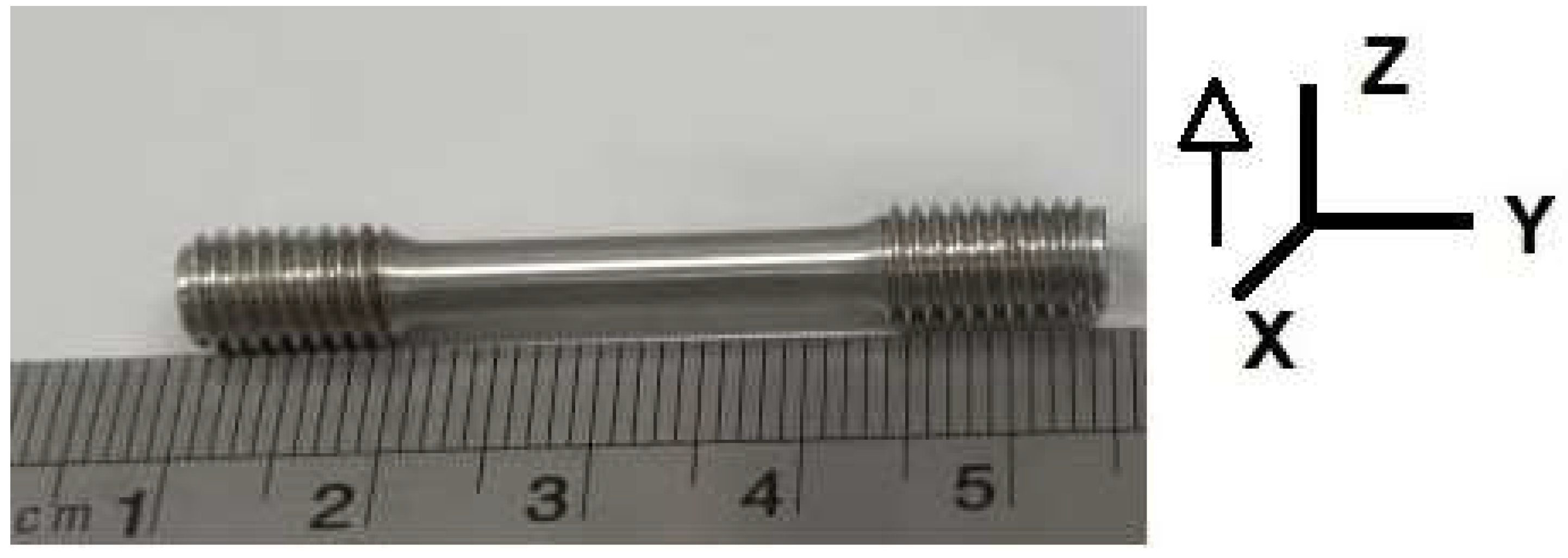
Figure 1 shows the machined tensile sample based on ASTM E8 standards illustrating the building direction scheme.
3. Results
3.1. Microstructure Analyses of the Al-7Si-0.7Mg-2.5Fe Powder
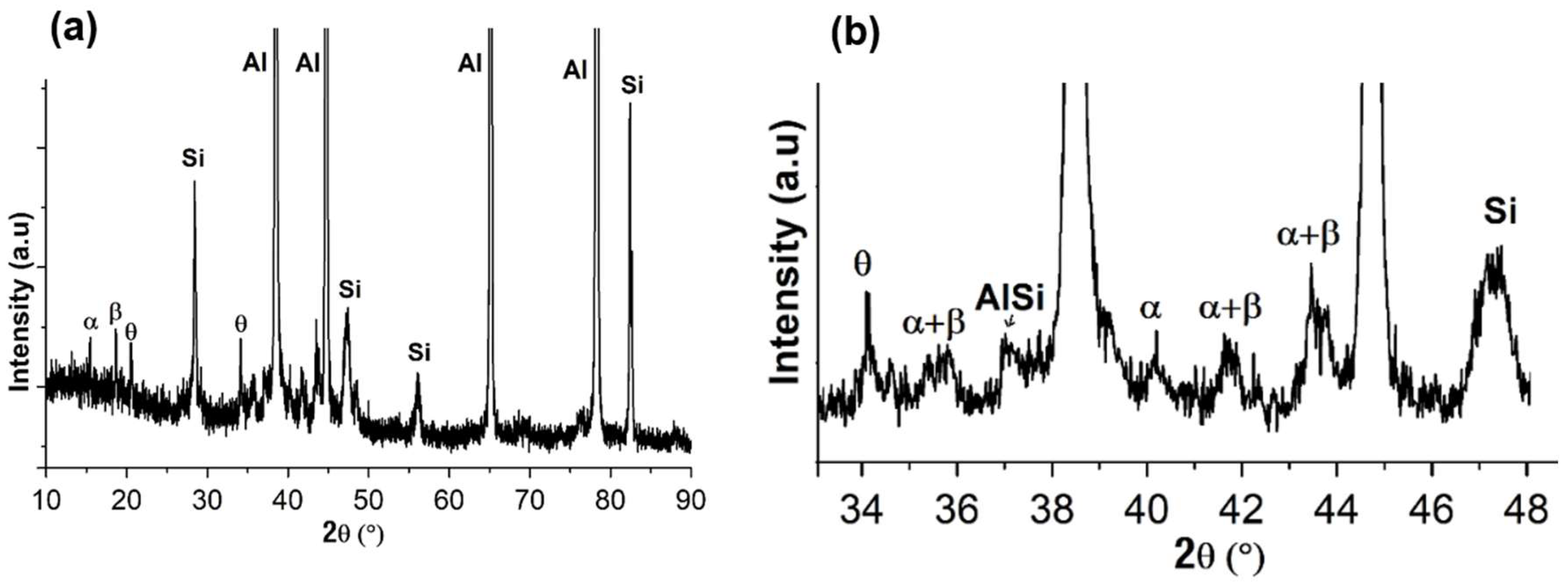
Figure 2(a) presents the overall XRD pattern of the Al-7Si-0.7Mg-2.5Fe powder. The peaks were indexed as corresponding to the phases α-Al, Si, β-Al
5FeSi, α-Al
8Fe
2Si, and tetragonal Al
9FeSi
3 (identified as θ), and can be better observed with an expanded detail of the XRD pattern, see
Figure 2(b
).
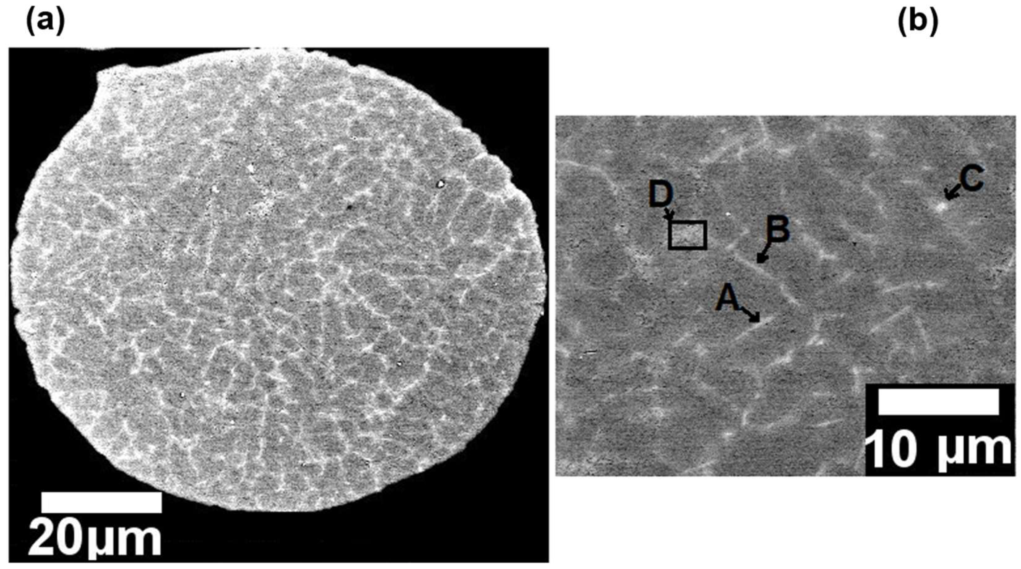
Figure 3 (a) presents a SEM micrograph of a spherical particle powder and its cellular structure.
Figure 3 (b) presents an expanded detail of the
Figure 3 (a) indicating the labeled points A, B, C, and D which correspond to needle-shaped intermetallic phases. Furthermore, as presented in
Table 2 which shows the results of the quantitative EDS chemical analyses performed in the labeled points A, B, C and D in
Figure 3 (b), the Fe contamination led to the formation of Fe-rich intermetallics phases even under the relatively high cooling rates prevailing in the atomization process, which may achieve values between 10
3–10
5 K/s [
16]. According to
Table 2, the labeled points A and B in
Figure 3 (b) present stoichiometric composition corresponding to the β-Al
5FeSi phase, while point C approximates the α-Al
8Fe
2Si composition, and D is similar to eutectic Al-Si.
Figure 3.
- SEM micrograph of the particle powder: (a) morphology; and (b) microstructure with labeled points indicating the needle-shaped intermetallic phases.
Figure 3.
- SEM micrograph of the particle powder: (a) morphology; and (b) microstructure with labeled points indicating the needle-shaped intermetallic phases.
Table 2.
– EDS measurements from the points labeled in
Figure 3 (b).
Table 2.
– EDS measurements from the points labeled in
Figure 3 (b).
| at.% |
Al |
Si |
Mg |
Fe |
| A |
87.2 |
6.6 |
0.1 |
6.1 |
| B |
84.9 |
9.3 |
0.5 |
5.3 |
| C |
88.4 |
7.7 |
0.5 |
3.4 |
| D |
87.6 |
11.2 |
0.7 |
0.5 |
3.2. Microstructure Analyses of the LPBF Sample
3.2.1. Optical Microscopy
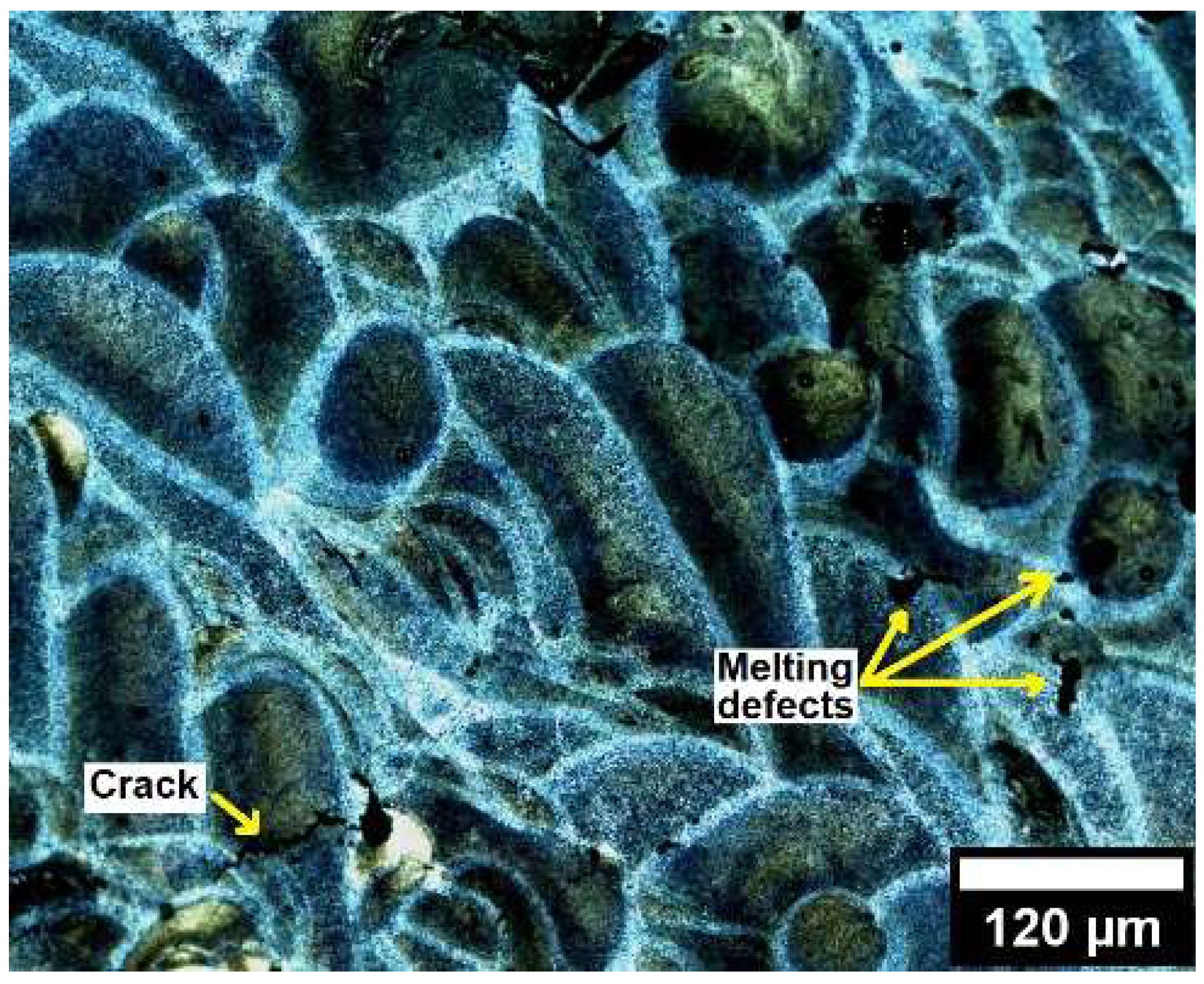
The microstructure of the LPBF sample was examined by optical microscopy (OM) to verify the effect of Fe-contamination during the solidification of the LPBF tracks . According to Moustafa [
6], the formation of needle-shaped morphology β-Al
5FeSi phase may act as a barrier during the solidification of Fe-contaminated AlSi cast alloys preventing the liquid metal to fill the spaces around the needles, leading to the formation of melting defects such as shrinkage crack and porosity.
Figure 4 shows an optical image of some small cracks and melting defects in the LPBF tracks. However, optimized LPBF parameters may minimize the cracks, porosity, and melting defects incidence [
15]. Further investigation of the optimized parameters of Fe-containing AlSiMg LPBF alloys is beyond of the scope of this work and should be addressed in the future.
3.2.2. Scanning Electron Microscopy (SEM), Transmission Electron Microscopy (TEM), and Energy Dispersive X-ray (EDS) Analyses of the As-Printed LPBF Sample
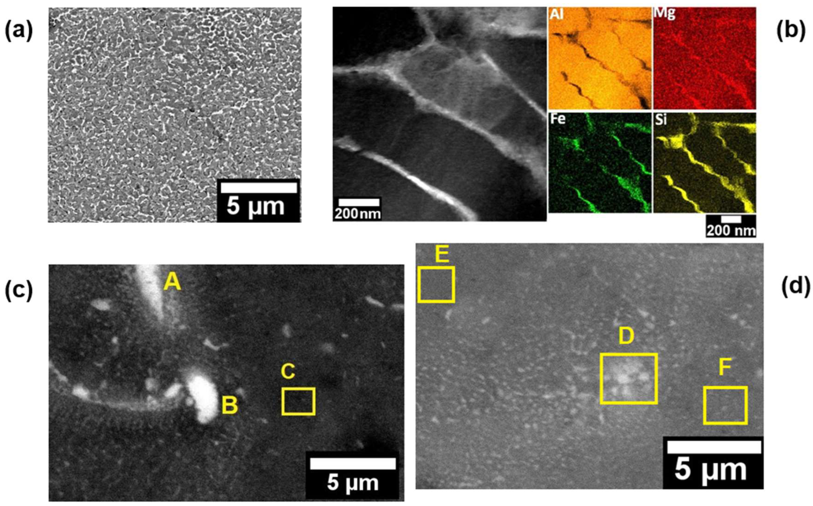
Figure 5 (a) shows a SEM image of the cellular structure found on the LPBF microstructure. Several studies regarding AlSiMg LPBF alloys describe this structure as a submicron eutectic Si network, which is a result of high cooling rates [
11,
12,
17,
18,
19]. Yang et al. [
19], presented detailed results regarding the effect of the eutectic Si network on mechanical properties. They identified that the formation of the eutectic Si network increased the yield strength and hardness, while the ductility decreased. However, solution heat treatment and stress relieving emerge as an alternative to adjust mechanical properties, once they may breaking up this network structure increasing the elongation to fracture [
17].
Figure 5 (b) shows a dark-field (DF) TEM image at a higher magnification of the nano-cellular structure and the respective EDS mapping for Al, Si, Mg and Fe, which indicates that the nano-cellular network is constituted by Si, Fe and Mg. In general, EDS chemical analyses are widely used to identify Si and Mg at the network boundaries and supersaturated solid solutions in the AlSiMg processed by LPBF [
16].
Figure 5 (c-d) present SEM images illustrating the observed Fe-rich intermetallic phases and the labeled points A, B, C, D, E and F indicating the EDS chemical analyses presented in
Table 3. Is possible to identify rounded and needle-shaped morphologies measuring between 1-3 µm in diameter and length, respectively.
3.2.3. X-ray Diffraction (XRD)
XRD analysis was performed to identified the phases formed on the microstructure of the Al-7Si-0.7Mg-2.5Fe alloy after the LPBF process.
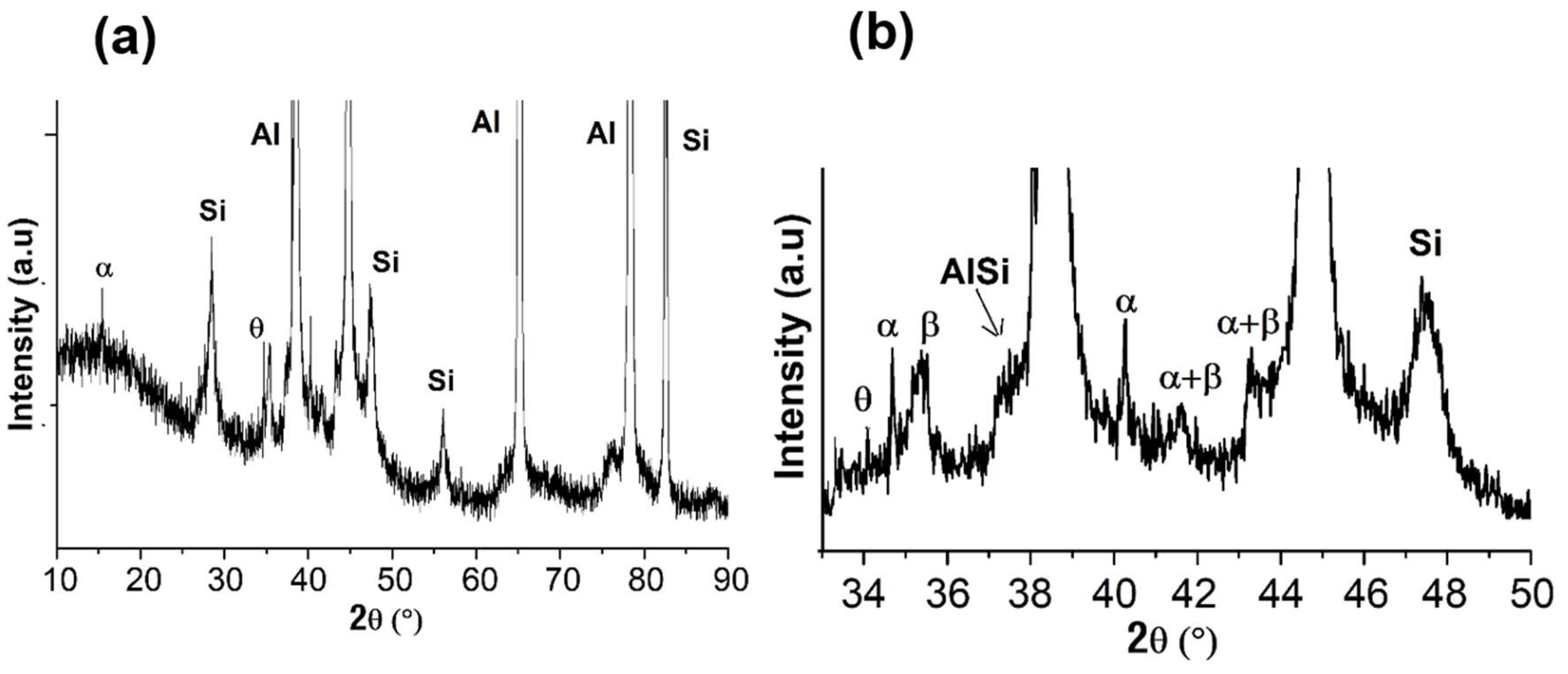
Figure 6 presents the XRD patterns of the LPBF sample, which identify the same phases presented in the powder microstructure (Al, Si, β-Al
5FeSi, α-Al
8Fe
2Si, and θ-Al
9FeSi
3), despite the different cooling rates prevailing in each process, being the LBPF faster as can be derived by comparing
Figure 3 a,b and
Figure 5 a,b. It is interesting to point out that the LBPF also presents segregation, however, at the nanoscale.
3.3. Microstructure of the LPBF Al-7Si-0.7Mg-2.5Fe Alloy after Heat Treatments
3.3.1. Scanning Electron Microscopy (SEM) and Energy Dispersive X-ray (EDS) Analyses
Heat treatments are widely applied to improve the mechanical properties of low Fe-containing AlSiMg LPBF alloys by dissolving part of the Si eutectic network increasing the ductility and providing precipitation hardening in the matrix [
20,
21,
22,
23,
24,
25]. The LPBF Al-7Si-0.7Mg-2.5Fe alloy was subjected to the heat treatment conditions presented in
Table 4. After each heat treatment procedure (SHT, AA, and DAA), quenching was performed in water at room temperature.
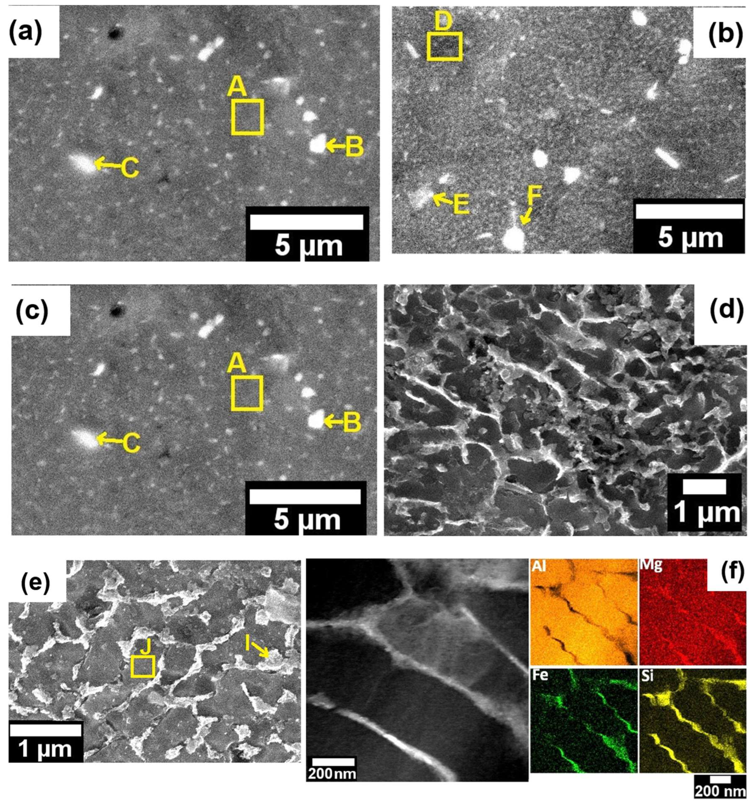
Figure 7 presents the SEM images of the microstructure of the LPBF Al-7Si-0.7Mg-2.5Fe alloy after heat treatments.
Table 5 shows the EDS measurements from the labeled points A, B, C, D, E, F, G, H, I, and J presented in
Figure 7.
Figure 7 (a) shows the microstructure of the LPBF Al-7Si-0.7Mg-2.5Fe alloy after condition 1 (SHT 520°/1 h + AA 160°/3 h), is possible to observe the precipitation of rounded (or, most probably, the spheroidization of the already present phases, particles labeled as B and C, for example) particles which according to
Table 5 are AlSiMgFe phases. Furthermore, is not possible to identify clearly the Si, Mg, and Fe cellular network found in the as-printed LPBF condition discussed in the previous section (showed again in
Figure 7(f)) to make easier the comparison), however, it is possible to identify some fine precipitation in the matrix (size at the nanoscale).
Figure 7 (b) shows the microstructure of the LPBF Al-7Si-0.7Mg-2.5Fe alloy after condition 2 (SHT 520°/1 h + AA 160°/6 h). As well as for condition 1, the condition 2 presents similar AlSiMgFe rounded particles( E and F, for example), and is not possible to identify the Si, Mg, and Fe cellular network clearly. The precipitation of a larger quantity of particles at the nanoscale are observed.
Figure 7 (c), shows the microstructure of the LPBF Al-7Si-0.7Mg-2.5Fe alloy after condition 3 (SHT 520°/1 h + AA 160°/12 h). The phases formed in the microstructure of LPBF Al-7Si-0.7Mg-2.5Fe during the heat treatment condition 3 are similar to the rounded morphology AlSiMgFe phases found for condition 2, exhibited in
Figure 7 (a,b), however, there is some coarsening of these particles.
Figure 7(d) and
Figure 7(e), present the microstructure of the LPBF Al-7Si-0.7Mg-2.5Fe alloy after directly artificial ageing (DAA) condition 5 (DAA 160°/6 h), and condition 6 (DAA 160°/12 h), respectively.
Observing
Figure 7 (d-e), it is possible to identify that the eutectic Si network remained intact on the microstructure of the LPBF Al-7Si-0.7Mg-2.5Fe alloy after DAA. Comparing the network structure for the two DAA conditions, longer time of ageing led to a coarser network structure.
3.3.2. Transmission Electron Microscopy (TEM) and Energy Dispersive X-ray (EDS) Analyses
Further microstructural analyses performed by TEM are presented in this section.
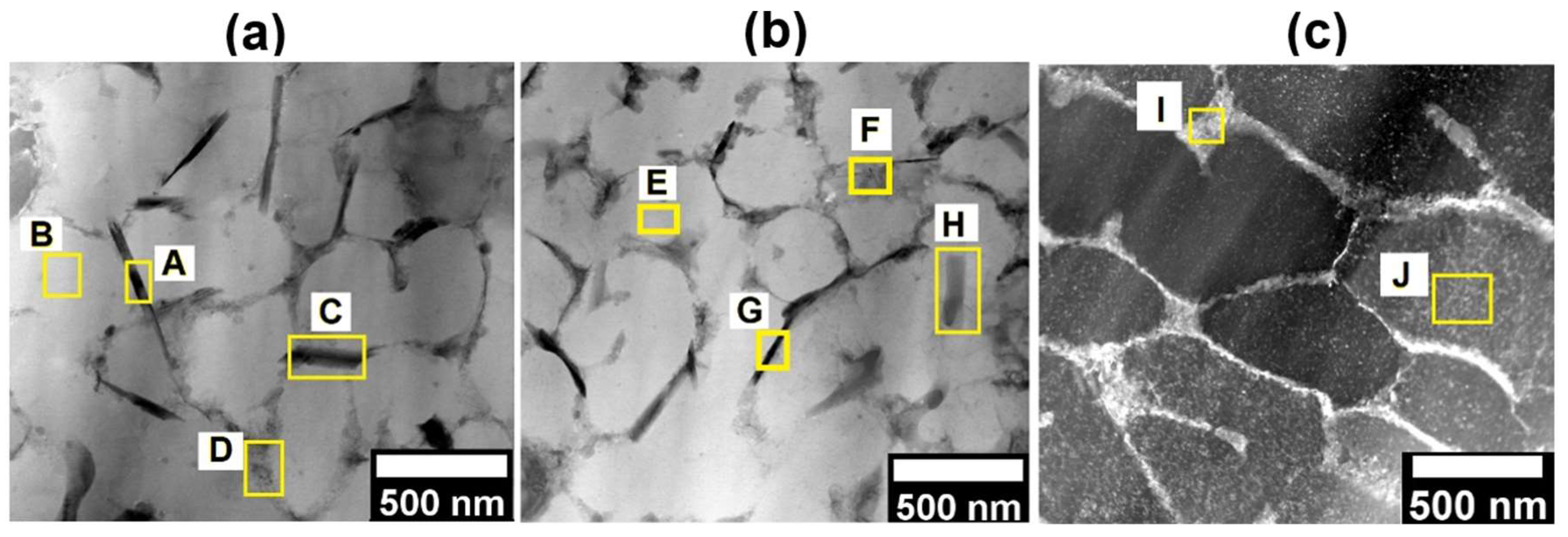
Figure 8 compares the microstructure of the LPBF Al-7Si-0.7Mg-2.5Fe alloy after directly artificial ageing (DAA) with the as-printed one. The labeled points A, B, C, D, E, F, G, H, I, and J indicate the EDS analyses presented in
Table 6. It is possible to identify on the DAA microstructure (
Figure 8 (a), and
Figure 8 (b)) a couple of nano MgSi-rich phases with needle-shaped morphology (points A, C, and G). These precipitates were not identified in
Figure 8 (c) whish shows a BF TEM images for the as-printed condition. Furthermore, for longer ageing time (DAA at 160°/12 h) (
Figure 8 (b)), compared to
Figure 8 (a) (DAA at 160°/6 h) it was possible to identify a Mg enrichment in the intermetallic phases with needle-shaped morphology represented by F, G, and H labeled points in
Figure 8 (b) and
Table 6.
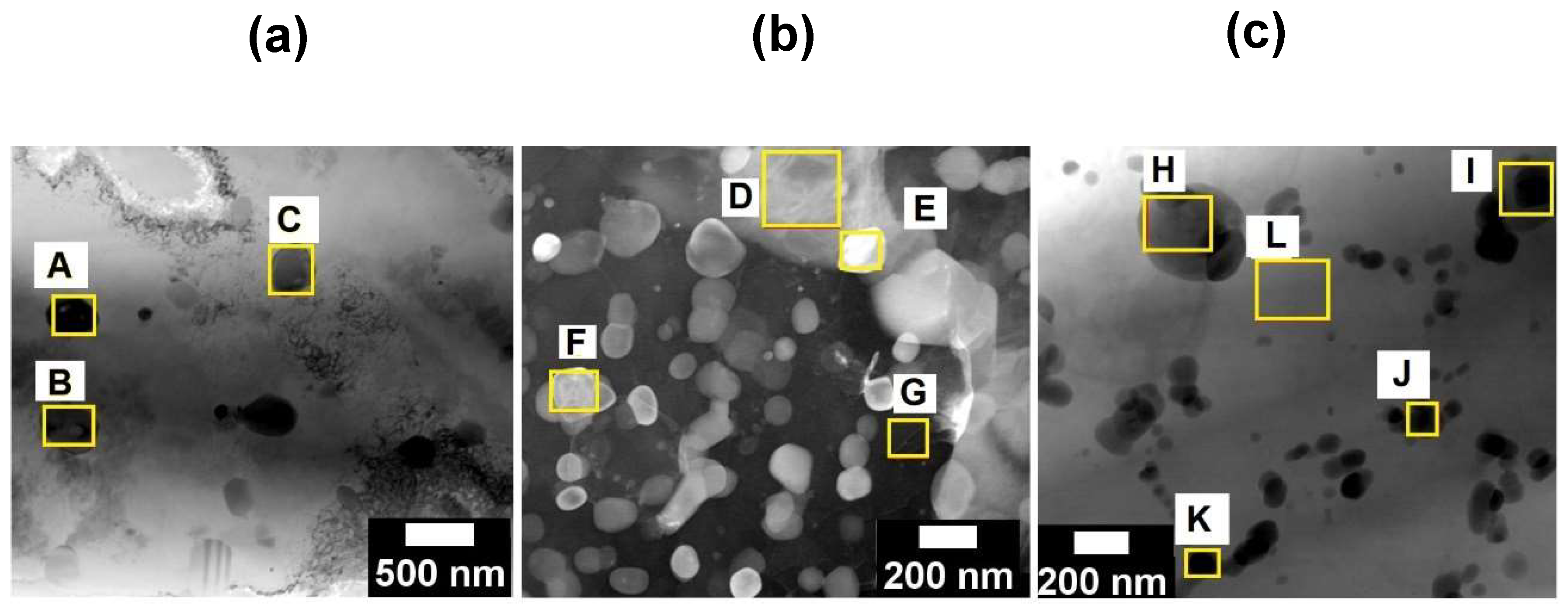
Figure 9 compares the microstructures SHT+AA. The labeled points A, B, C, D, E, F, G, H, I, J, K, and L indicate the EDS analyses presented in
Table 7. Observing the labeled points A, B, and C in
Figure 9 (a) for condition 2 (SHT 520°/1 h + AA 160°/3 h), is possible to identify SiMg-rich nanoparticles with the Si amount higher than the Mg amount. Moreover, a relatively higher amount of Fe compared to the maximum Fe solubility in the Al matrix was observed. These SiMg-rich nanoparticles were not observed for condition 3 (SHT 520°/1 h + AA 160°/6 h) presented in
Figure 9 (b).
However, observing the microstructure of condition 3 (SHT 520°/1 h + AA 160°/12 h) presented in
Figure 9 (c), is possible to identify SiMg-rich nanoparticles similar to those presented in
Figure 9 (a). Comparing the chemical compositon of the phases found in
Figure 9 (a) and
Figure 9 (c), the phases found in
Figure 9 (c) present lower SiMg amount, although the amount of Si is still higher than the amount of Mg and Fe.
According to the microstructural results of the heat treated studied alloy presented so far, it is worth to highlight that the precipitation mechanism observed for DAA is related to the formation of SiMg particles with needle-shaped morphology in the cellular network boundaries. Moreover, for longer ageing times (DAA 160°/12 h), resulted in an enrichment of Mg accompanied by a decrease of the Si amount.
3.4. Mechanical Properties of the As-Printed and Heat Treated LPBF Al-7Si-0.7Mg-2.5Fe Alloy
Tensile tests were performed to investigate the mechanical properties of the as-printed and heat treated conditions.
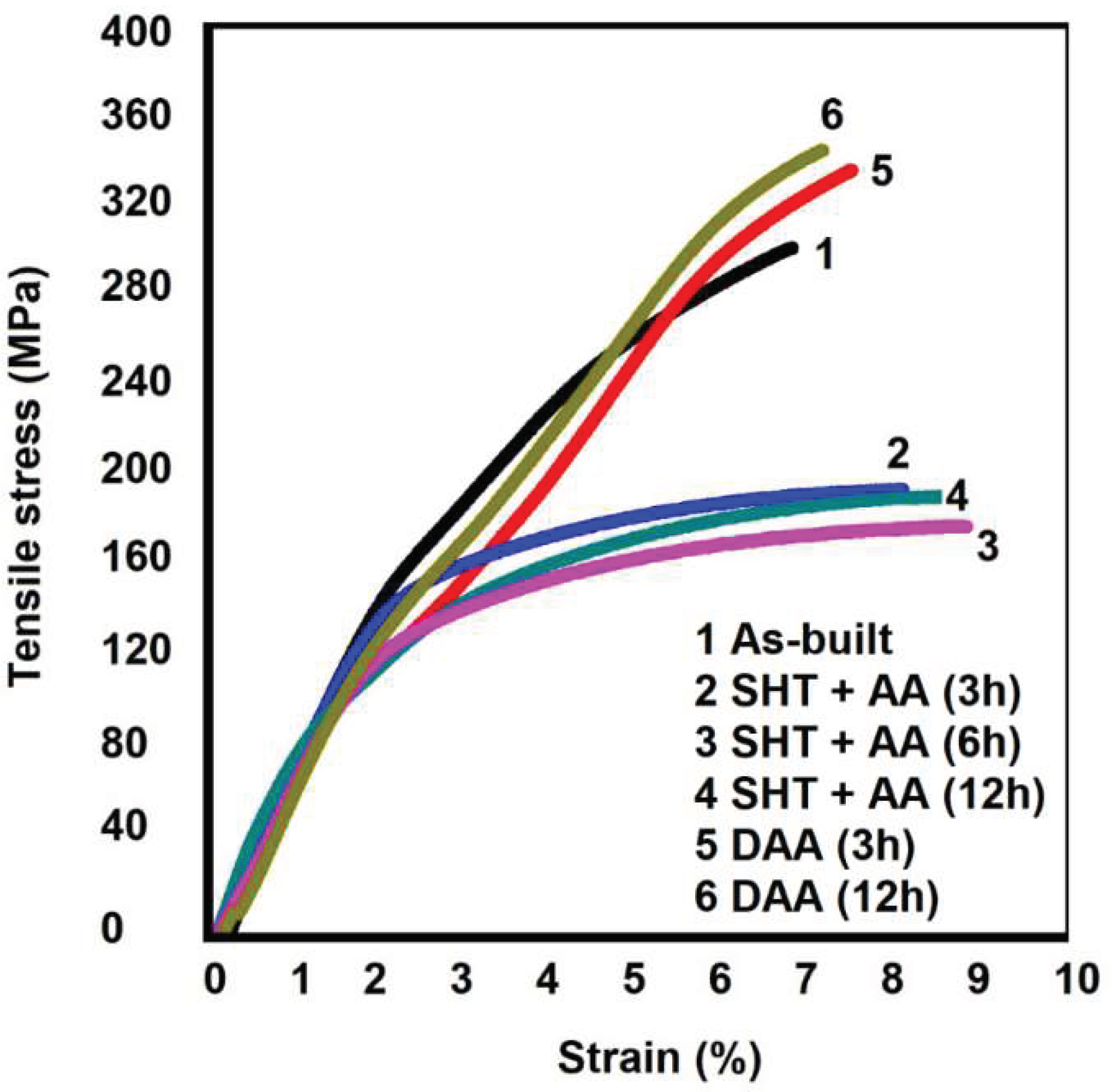
Figure 10 presents the engineering stress-strain curves for the LPBF as-printed and heat treated samples.
The Ultimate Tensile Stress (UTS) of the as-printed LPBF sample reached average values of about 300 MPa. On average, the presented Elongation to Fracture (EF) was around 6,5%.
Observing the engineering stress strain curves after SHT presented in
Figure 10 is possible to identificate a significant decrease in the yield strain, and a slight improvement in the elongation to the fracture for conditions 2 (SHT 520°/1 h + AA 160°/3 h), 3 (SHT 520°/1 h + AA 160°/6 h), and 4(SHT 520°/1 h + AA 160°/12 h) problaby due to the partial dissolution of the SiMgFe cellular network, which was indicated in
Figure 7 (a-b-c).
Regarding DAA conditions, UTS and EF average values were respectively 330 MPa, and 7,5% for condition 5 (DAA at 160°/6 h), while for condition 6 (DAA at 160°/12 h), the UTS average value reached 350 MPa, and EF was about 7,2%. Comparing to the as-printed values (condition 1), a tendency to an slight improvement in the mechanical properties was noted, however, it must be pointed out that the values among the different conditions lie within the statistical scattering.
Table 8 compares the mechanical properties values for the as-printed and heat treated LPBF conditions to mechanical properties values for the LPBF Al-7Si-Mg alloys without Fe contamination. According to
Table 8, the investigated mechanical properties for the studied alloy are similar to values reported in previous studies. The UTS values are between 308 ~ 408 MPa, while EF values are between 4 ~11 % for LPBF alloys without Fe. Compared to the cast Al-7Si-Mg, the studied alloy presents higher mechanical properties values once the maximum UTS value is about 305 MPa, while the maximum EF is about 4% for cast alloys with Fe content below 0.3% [
25].
4. Discussion
4.1. Microstructure Analyses of the Al-7Si-0.7Mg-2.5Fe Powder
The formation of needle-shaped intermetallic phases on the powder microstructure of the Al-7Si-0.7Mg-2.5Fe alloy even under the relatively high cooling rates leads us to infer that the mechanical properties of the studied alloy might be highly impaired by further processing [
5].
4.2. Cracks and Melting Defects on the Microstructure of Al-7Si-0.7Mg-2.5Fe LPBF Sample
In general, cracks and melting defects are features of the LPBF process, being cracks associated to thermal contraction during LPBF solidification, while melting defects are associated to laser and powder interactions during the layers printing process [
26,
27]. As cracks and melting defects are frequently reported in studies regarding LPBF process even for primary AlSi alloys with low iron contents, the effect of Fe-contamination in the formation of pores and shrinkage cracks is not conclusive in this paper. However, the low incidence of such defects, comparable to the results obtained with primary alloys [
28], may suggest that the influence of 2.5wt%Fe, if any, was negligible. And this might be a consequence of the nanoscale dispersion of the intermetallics.
4.3. Microstructure Characterization of the As-Printed Al-7Si-0.7Mg-2.5Fe Alloy
The XRD analysis for the as-printed LPBF sample identifyed the same phases presented in the powder microstructure (Al, Si, β-Al
5FeSi, α-Al
8Fe
2Si, and θ-Al
9FeSi
3). However, further microscopy analysis showed that the LPBF process led to a microstructural refinement, formation of a submicron cellular network and changed the phases morphologies. According to
Figure 5 and
Table 3, the submicron cellular network boundaries and the intermetallic phases are constituted by Al, Si, Mg, and Fe. In general, the cellular network boundaries are constituted by nano-particle of eutectic Si and Mg. The presence of Fe at the cellular submicron network boundaries indicates a Fe nano-segregation probably due the relatively high amount of Fe in the studied alloy. According to
Figure 5 (c-d) and the EDS chemical analyses presented in
Table 3, the observed intermetallic phases are constituted by Al, Si, Mg, and Fe, which could means their growth may be competing with the growth of the cellular network boundaries, or precipitating as a result of the super saturation of the Al-matrix. Moreover, it was not possible to show clearly the eutectic Si network structure and the AlSiFe intermetallic phases in the same image.
The high level of Fe-contamination led to the formation of AlSiFe, although the high cooling rate applied by gas atomization and still higher by LPBF provided a refined microstructure, once both processes presented a cellular structure and AlSiFe intermetallic phases with sizes around 5 μm for gas atomization and at the nanoscale for LBPF. Therefore, the LPBF solidification dynamic presented rounded AlSiFe intermetallics, which according to previous studies are formed from the liquid metal at temperatures above the SHT at 520 °C [
29]. This is arguable as there is no evidence by observing
Figure 5 that the intermetallic fomed at the nanocellular boundaries are formed during the solidification. The picture suggest that the nanosegregation at the sub-cell boundaries led in fact to the enrichment of Si and Fe in these regions, however, it did not suffice to trigger an eutectic reaction as it does in the cell boundaries (see
Figure 5(a)). Indeed,
Figure 5 (b) suggest that the phases decorating the nanocell boundaries were formed in solid state during cooling after solidification or reheating provoked by the next melting tracks. Thus, in addition to the deleterious effect on ductility, the AlSiFe intermetallic formation also could decrease the precipitation hardening of the AlSiMg LPBF alloys due to the Si present in AlSiFe intermetallics remaining reclused during the SHT leading to a lower amount of Si available in solid solution in the matrix. Comparing with the powder, the microstructure of the LPBF samples were completely changed during solidification under LPBF condition, indicating that the remelting process led the material to solidify under completely diferent conditions. A nanoscale structure was developed within the tracks, which dispersed strongly the iron-containing intermetallics, reducing their sizes to the nanoscale. Still some micro-intermetallics can be found, probably, as a consequence of agglomeration during the multiple remelting. However, the presence of these nanosegregation was prevalent on the microstructure, which could be observed clearly only by high magnification SEM and TEM images. Therefore, the LPBF process is an effective way to mitigate the effect of high iron content on the AlSi alloys.
4.4. Microstructure Characterization of the LPBF Al-7Si-0.7Mg-2.5Fe Alloy after Heat Treatments
After SHT heat treatment, the cellular network constituted by Si, Mg, and Fe was partially disconnected originating a fragmented pseudo network constitute by Si, AlSiFe, and AlSiMgFe particles, with the vast majority of rounded particles. The number of precipitates formed, as well as the particle size increased for longer ageing times after SHT. Although it is not conclusive observing the labeled points A, B, and C in
Figure 7 (a-c) and
Table 5, studies regarding the heat treatment of AlSiMg alloys associated this phenomena with the dissolution of the as-printed supersaturated matrix during SHT which leads to precipitation and coarsening of Si and Mg2Si along the previous cellular network boundaries [
17,
22]. This is, however, arguable as the SHT temperature would not be high enough to dissolve the AlFeSi intermellics. Most probably, as the pictures indicated, there is a partial dissolution and fragmentation of the network at the cell boundaries and a spheirodization of the AlFeSi and Si particles. The subsequent ageing at low temperature (160 °C) led to the fine precipitation in the matrix formed by the segregated elements present at the subcell boundaries that are dissolved into the matrix during the SHT.
Regarding the microstructure of the LPBF Al-7Si-0.7Mg-2.5Fe alloy after DAA, was possible to observe in
Figure 7 (d-e) that the eutectic Si network remained intact on the microstructure of the LPBF Al-7Si-0.7Mg-2.5Fe. Furthermore, comparing the network structure for the two DAA conditions, longer time of ageing led to a coarser network structure. It is widely known that the ageing temperature is basically too low to dissolving eutectic Si, intermetallic phases or even providing conditions for Si diffusion. However, the high Si content in solid solution in the as-printed LPBF sample leads to the formation of Si and Mg precipitates nearby the cell boundaries leading to a coarser network after ageing [
17].
Previous studies also identifyed a cellular network coarsening of LPBF AlSiMg alloys after direct artificial ageing and associated it to the precipitation and growth of nano Mg2Si phase in it boundaries [
17,
24]. The LPBF Al-7Si-0.7Mg-2.5Fe alloy presented a similar behavior; as the SHT treatment was not performed before artificial ageing, the SiMgFe cellular network remained intact while the needle-shaped Mg2Si particles precipitate and grow during the artificial ageing. The precipitation and growth of nano Mg2Si phase in the SiMgFe cellular network boundaries may lead to a strengthening of the LPBF Al-7Si-0.7Mg-2.5Fe alloy accompanied by a reduced ductility after DAA once the cellular network acts as a dislocation barrier [
17,
23].
Fiochi et al. [
23], classified the microstructural characterization of heat treated LPBF AlSiMg alloys as a complex process due to discrepancies presented in several works regarding the precipitation sequence of the Si and Mg particles.
Regarding artificial ageing after SHT, the Si and Mg precipitation are concomitant, forming rich SiMg particles for shorter ageing times, while longer ageing times led to the formation of particles with relatively lower Si and Mg amount.
Considering the relatively high amount of Fe for the Al alloys, especially for Si-containing alloys such as the one studied in this work, no significant microstructural changes were identified regarding AlSiMg LBPF processed, and post-processed. On the other hand, regarding microstructural engineering and aluminum recycling, the formation of nano Fe-rich intermetallic may provide an improvement in the ductility of recycled alloys.
4.5. Mechanical Properties of the LPBF Al-7Si-0.7Mg-2.5Fe Alloy after Heat Treatments
The fine AlSiFeMg and Si intermetallic phases formed at the cellular network, as well as the amount of Si and Mg in solid solution identified on the microstructure of the studied alloy could act as barriers for dislocation motion leading to the exhibited strain hardening rate. Furthermore, considering the relatively high amount of Fe present in the studied alloy, the formation of nanosize Fe-rich intermetallics lead to an improvement of elongation to the fracture compared to the predicted values in the literature for Fe-contaminated AlSiMg alloys [
5].
The decrease in the yield strain, and a slight improvement in the elongation to the fracture exhibited for conditions 2 (SHT 520°/1 h + AA 160°/3 h), 3 (SHT 520°/1 h + AA 160°/6 h) and 4(SHT 520°/1 h + AA 160°/12 h) could be related to the partial dissolution of the SiMgFe cellular network presented in
Figure 7 (a-b-c) [
30].
Regarding DAA conditions, a slight improvement in the mechanical properties was noted when compared to the as-printed values (condition 1). However, it must be pointed out that the values among the different conditions lie within the statistical scattering. This means that the conditions of the DAA treatment did not suffice to change significantly the microstructural features observed in the as built condition, i.e, predominatly high saturation of the matrix, nanosized particles at subcell boundaries and maintenance of the segregation at the cell boundaries.
The results presented in this study indicate that the LPBF process may be an alternative recycling route for Fe-contaminated Al-7Si-Mg alloys once the LPBF solidification dynamic attenuates the deleterious Fe effects on the mechanical properties. Moreover, the results showed that the investigated heat treatment conditions provided no significant changes on the microstructure and mechanical properties compared to the as-printed condition. The efficiency of SHT in ductility improvement as predicted in the literature was not proved for the studied alloy. Despite the high precipitation hardening provided by Mg2Si when formed in the matrix of aluminum alloys, it had no effect when formed at the cellular network boundaries. The partial dissolution of AlSiMgFe network and Mg2Si formation in its boundaries led to a considerable UTS decrease while the ductility remains almost unchanged when compared to the as-printed and DAA conditions. The as-printed and DAA conditions present higher hardening rates due to the cellular network and, Si and Mg in solid solution, which are dissolved after SHT.
It's worth to point it out that further studies regarding LPBF parameters optimization are required, once the LPBF parameters may lead to enhancements in the mechanical properties of LPBF Al-7Si-Mg alloys.
5. Conclusions
The effects of processing and post-processing conditions on the microstructure and mechanical properties of the Al-7Si-0.7Mg-2.5Fe alloy produced by LPBF were examined.
Considering the relatively high amount of Fe in the studied alloy, all conditions evaluated in this paper presented satisfactory microstructure and mechanical properties results compared to Al-7Si-0.7Mg with low Fe content produced by LPBF processes.
The formation of the nanoscale cell structure contributed to mitigating/avoiding the formation and coarsening of deleterious Si and AlFeSi intermetallic phases such as β-Al5FeSi and α-Al8Fe2Si.
The partial dissolution of the nano and microsized cellular AlSiFe network during SHT provided a slight improvement in elongation to the fracture, however, it decreased the ultimate tensile strain significantly.
In addition to a cellular network coarsening, DAA conditions led to the formation of needle-shaped MgSi intermetallics at the cellular network boundaries providing a slight strengthening compared to the as-printed condition.
Author Contributions
Conceptualization, L.H., W.B. and C.B.; methodology, L.H., P.B., L.O., B.F., P.G., and C.K.; validation, L.H., P.B., L.O., B.F., P.G., C.K. W.B. and C.B.; investigation, L.H., L.O., B.F., W.B. and C.B.; data curation, L.H., W.B. and C.B.; writing original draft preparation, L.H., W.B. and C.B.; writing review and editing, L.H., W.B. and C.B.; supervision, W.B. and C.B.; project administration, L.H., W.B. and C.B. All authors have read and agreed to the published version of the manuscript.
Funding
This research was funded in part by the Coordenação de Aperfeiçoamento de Pessoal de Nível Superior- Brasil (CAPES)-Finance Code 88887.357895/2019-00. The authors also thank the Brazilian Research Funding agencies: Fundação de Amparo à Pesquisa do Estado de São Paulo/FAPESP (Thematic Project, Grant No. 2013/05987-8 and 2017/27031-4), and Conselho Nacional de Desenvolvimento Científico e Tecnológico/CNPq.
Data availability
Data will be made available on request.
Acknowledgments
The authors would like to thank the Coordenação de Aperfeiçoamento de Pessoal de Nível Superior- Brasil (CAPES)-Finance Code 88887.357895/2019-00. The authors also thank the Brazilian Research Funding agencies: Fundação de Amparo à Pesquisa do Estado de São Paulo/FAPESP (Thematic Project, Grant No. 2013/05987-8 and 2017/27031-4), Conselho Nacional de Desenvolvimento Científico e Tecnológico/CNPq, and Coordenação de Aperfeiçoamento de Pessoal de Nível Superior/CAPES for the financial support. Additionally, the authors thank the Laboratory of Structure Characterization and Center for Characterization and Development of Materials (CCDM) of Department of Materials Engineering at the Federal University of São Carlos (LCE/DEMa/UFSCar), respectively for the mechanical characterization and microscopy facilities.
Declarations
On behalf of all authors, the corresponding author states that there is no conflict of interest.
References
- Zhang X, Chen C. Experimental investigation of joining aluminum alloy sheets by stepped mechanical clinching. J Mater Res Technol 2022, 19, 566. [CrossRef]
- Tisza M, Czinege I. Comparative study of the application of steels and aluminium in lightweight production of automotive parts. Int J Light Weight Mater Manuf 2018, 1, 229e38. [CrossRef]
- Buchner H, Laner D, Rechberger H, Fellner J. Potential recycling constraints due to future supply and demand of wrought and cast Al scrap—A closed system perspective on Austria. Resour Conserv Recycl [Internet]. 2017, 122, 135–142. [CrossRef]
- 4. Zhu Y, Chappuis LB, De Kleine R, Kim HC, Wallington TJ, Luckey G; et al. The coming wave of aluminum sheet scrap from vehicle recycling in the United States. Resour Conserv Recycl [Internet]. [CrossRef]
- Ji S, Yang W, Gao F, Watson D, Fan Z. Effect of iron on the microstructure and mechanical property of Al-Mg-Si-Mn and Al-Mg-Si diecast alloys. Mater Sci Eng A [Internet]. 2013, 564, 130–139. [CrossRef]
- Moustafa, MA. Effect of iron content on the formation of β-Al5FeSi and porosity in Al-Si eutectic alloys. Vol. 209. Journal of Materials Processing Technology, 605–610.
- Freitas BJM, Otani LB, Kiminami CS, Botta WJ, Bolfarini C. Effect of iron on the microstructure and mechanical properties of the spray-formed and rotary-swaged 319 aluminum alloy. Int J Adv Manuf Technol. 2019, 102, 3879–3894. [CrossRef]
- Yan Q, Song B, Shi Y. Comparative study of performance comparison of AlSi10Mg alloy prepared by selective laser melting and casting. J Mater Sci Technol [Internet]. 2020, 41, 199–208. [CrossRef]
- Cui J, Roven HJ. Recycling of automotive aluminum. Trans Nonferrous Met Soc China (English Ed [Internet]. 2010, 20, 2057–2063 Available from:. [CrossRef]
- 10. Coşkun M, Dizdar KC, Tarakçi G, Özer G, Dispinar D. Recycling of additive manufactured AlSi10Mg and its effect on mechanical properties. Mater Chem Phys.
- Rao H, Giet S, Yang K, Wu X, Davies CHJ. The influence of processing parameters on aluminium alloy A357 manufactured by Selective Laser Melting. Mater Des [Internet]. 2016, 109, 334–346. [CrossRef]
- Aboulkhair NT, Everitt NM, Ashcroft I, Tuck C. Reducing porosity in AlSi10Mg parts processed by selective laser melting. Addit Manuf [Internet]. 2014, 1, 77–86. [CrossRef]
- Manca DR, Churyumov AY, Pozdniakov A V, Ryabov DK, Korolev VA, Daubarayte DK. Novel heat-resistant Al-Si-Ni-Fe alloy manufactured by selective laser melting. Mater Lett [Internet]. 2019, 236, 676–679. [CrossRef]
- Kimura T, Nakamoto T, Ozaki T, Miki T. Microstructures and mechanical properties of aluminum-transition metal binary alloys (Al-Fe, Al-Mn, and Al-Cr) processed by laser powder bed fusion. J Alloys Compd [Internet]. 2021, 872, 159680. [CrossRef]
- G. Li, S.D. Jadhav, A. Martín, M.L. Montero-Sistiaga, J. Soete, M.S. Sebastian, C.M. Cepeda-Jiménez, K. Vanmeensel, Investigation of Solidification and Precipitation Behavior of Si-Modified 7075 Aluminum Alloy Fabricated by Laser-Based Powder Bed Fusion. Metallurgical and Materials Transactions A: Physical Metallurgy and Materials Science 2021, 52, 194–210. [CrossRef]
- Si C, Tang X, Zhang X, Wang J, Wu W. Characteristics of 7055Al alloy powders manufactured by gas-solid two-phase atomization: A comparison with gas atomization process. Mater Des [Internet]. 2017, 118, 66–74. [CrossRef]
- Zhang B, Wei W, Shi W, Guo Y, Wen S, Wu X; et al. Effect of heat treatment on the microstructure and mechanical properties of Er-containing Al-7Si-0.6 Mg alloy by laser powder bed fusion. J Mater Res Technol [Internet]. 2022, 18, 3073–3084. [CrossRef]
- Cheng CC, Li Z, Dhillon JS, Hudon P, Brochu M. Influence of powder layer thickness on microstructure and T5 heat treatability of F357 alloy fabricated by laser powder bed fusion process. J Alloys Compd [Internet]. 2023, 948, 169633. [CrossRef]
- Shyinti C, Walter K. Predicting the Formation of Intermetallic Phases in the Al-Si-Fe System with Mn Additions. 2017, 298–304.
- Zhou L, Mehta A, Schulz E, McWilliams B, Cho K, Sohn Y. Microstructure, precipitates and hardness of selectively laser melted AlSi10Mg alloy before and after heat treatment. Mater Charact [Internet]. 2018, 143, 5–17. [CrossRef]
- Wang LF, Sun J, Yu XL, Shi Y, Zhu XG, Cheng LY; et al Enhancement in mechanical properties of selectively laser-melted AlSi10Mg aluminum alloys by T6-like heat treatment. Mater Sci Eng A. 2018, 734, 299–310. [CrossRef]
- Li W, Li S, Liu J, Zhang A, Zhou Y, Wei Q; et al. Effect of heat treatment on AlSi10Mg alloy fabricated by selective laser melting: Microstructure evolution, mechanical properties and fracture mechanism. Mater Sci Eng A [Internet]. 2016, 663, 116–125. [CrossRef]
- 23. Fiocchi J, Tuissi A, Biffi CA. Heat treatment of aluminium alloys produced by laser powder bed fusion: A review. Mater Des.
- Fousová M, Dvorský D, Michalcová A, Vojtěch D. Changes in the microstructure and mechanical properties of additively manufactured AlSi10Mg alloy after exposure to elevated temperatures. Mater Charact. 2018, 137, 119–126. [CrossRef]
- Aversa A, Lorusso M, Trevisan F, Ambrosio EP, Calignano F, Manfredi D; et al. Effect of process and post-process conditions on the mechanical properties of an A357 alloy produced via laser powder bed fusion. Metals (Basel). 2017, 7, 1–9.
- H.R. Kotadia, G. Gibbons, A. Das, P.D. Howes, A review of Laser Powder Bed Fusion Additive Manufacturing of aluminium alloys: Microstructure and properties. Additive Manufacturing. [CrossRef]
- C. Weingarten, D. Buchbinder, N. Pirch, W. Meiners, K. Wissenbach, R. Poprawe, Formation and reduction of hydrogen porosity during selective laser melting of AlSi10Mg. Journal of Materials Processing Technology. 2015, 221, 112–120. [CrossRef]
- Qian W, Wu S, Wu Z, Ahmed S, Zhang W, Qian G; et al. In situ X-ray imaging of fatigue crack growth from multiple defects in additively manufactured AlSi10Mg alloy. Int J Fatig 2022, 155, 106616. [CrossRef]
- L.H. Pereira, G.H. Asato, L.B. Otani, A.M. Jorge, C.S. Kiminami, C. Bolfarini; et al., Changing the solidification sequence and the morphology of iron-containing intermetallic phases in AA6061 aluminum alloy processed by spray forming. Mater Charact [Internet] 2018, 145, 507–515. [CrossRef]
- K.G. Prashanth, S. Scudino, H.J. Klauss, K.B. Surreddi, L. L¨ober, Z. Wang; et al., Microstructure and mechanical properties of Al-12Si produced by selective laser melting: Effect of heat treatment. Mater Sci Eng A [Internet] 2014, 590, 153–160. [CrossRef]
Figure 1.
Machined tensile sample based on ASTM E8 standard with its longitudinal axis aligned with the Y direction, perpendicular to the building Z-LPBF direction .
Figure 1.
Machined tensile sample based on ASTM E8 standard with its longitudinal axis aligned with the Y direction, perpendicular to the building Z-LPBF direction .
Figure 2.
(a) - XRD pattern for the powder particles of the Al-7Si-0.7Mg-2.5Fe alloy; (b) expanded detail indicating the α-Al, Si, eutectic AlSi, β, α, θ and λ phases.
Figure 2.
(a) - XRD pattern for the powder particles of the Al-7Si-0.7Mg-2.5Fe alloy; (b) expanded detail indicating the α-Al, Si, eutectic AlSi, β, α, θ and λ phases.
Figure 4.
- Optical image of the LPBF tracks.
Figure 4.
- Optical image of the LPBF tracks.
Figure 5.
- Microstructure of the as-printed LPBF sample: (a) SEM image of the cellular structure; (b) DF image of the nano-cellular structure with the respective qualitative chemical mapping of Al, Si, Mg and Fe; and (c) and (d) SEM image of the intermetallics phases formed at microscale and labeled points indicating the EDS analyses presented in
Table 3.
Figure 6.
- (a) XRD pattern for the LPBF sample; (b) expanded detail indicating the Al, Si, eutectic AlSi, β, α, and θ phases.
Figure 6.
- (a) XRD pattern for the LPBF sample; (b) expanded detail indicating the Al, Si, eutectic AlSi, β, α, and θ phases.
Figure 7.
– SEM images of the microstructure after heat treatment: (a) condition 2 (SHT 520°/1 h + AA 160°/3 h); (b) condition 3 (SHT 520°/1 h + AA 160°/6 h); (c) condition 4 (SHT 520°/1 h + AA 160°/12 h); (d) condition 5 (DAA 160°/6 h); (e) condition 6 (DAA 160°/12 h); and (f) as printed sample included here for comparison purposes.
Figure 8.
– TEM microstructures after DAA. BF TEM images with labeled points indicating the EDS analyses presented in
Table 6: (a) condition 5 (DAA 160°/6 h); (b) condition 6 (DAA 160°/12 h); and (c) condition 1 (as-printed).
Figure 8.
– TEM microstructures after DAA. BF TEM images with labeled points indicating the EDS analyses presented in
Table 6: (a) condition 5 (DAA 160°/6 h); (b) condition 6 (DAA 160°/12 h); and (c) condition 1 (as-printed).
Figure 9.
- Microstructure after SHT + AA heat treatments. BF TEM images with labeled points indicating the EDS analyses presented in Table 7: (a) condition 2 (SHT 520°/1 h + AA 160°/3 h); (b) condition 3 (SHT 520°/1 h + AA 160°/6 h); and (c) condition 4 (SHT 520°/1 h + AA 160°/12 h).
Figure 9.
- Microstructure after SHT + AA heat treatments. BF TEM images with labeled points indicating the EDS analyses presented in Table 7: (a) condition 2 (SHT 520°/1 h + AA 160°/3 h); (b) condition 3 (SHT 520°/1 h + AA 160°/6 h); and (c) condition 4 (SHT 520°/1 h + AA 160°/12 h).
Figure 10.
- Engineering stress-strain curves for the LPBF as-printed and heat treated samples.
Figure 10.
- Engineering stress-strain curves for the LPBF as-printed and heat treated samples.
Table 1.
LPBF parameters.
Table 1.
LPBF parameters.
| Laser Scan speed (Vs) |
Laser power
(P) |
Layer thickness (t) |
Hatch space
(d) |
Energy density (Ev) |
| 1200 mm s-1
|
250 W |
30 µm |
100 µm |
69,4 j mm-3
|
Table 2.
Chemical composition of the ingots of AlSiMgFe (wt.%) alloy obtained by X-Ray Fluorescence.
Table 2.
Chemical composition of the ingots of AlSiMgFe (wt.%) alloy obtained by X-Ray Fluorescence.
| Al |
Si |
Mg |
Fe |
| Bal. |
6.1 |
0.63 |
2.5 |
Table 3.
- EDS measurements from the points labeled in
Figure 5 (c) and
Figure 5 (d).
Table 3.
- EDS measurements from the points labeled in
Figure 5 (c) and
Figure 5 (d).
| at.% |
Al |
Si |
Mg |
Fe |
| A |
91 |
3.8 |
0.8 |
4.3 |
| B |
88.2 |
4.6 |
0.8 |
6.4 |
| C |
84 |
14.9 |
0.9 |
0.2 |
| D |
96,1 |
2 |
0.8 |
1.1 |
| E |
94.9 |
3.7 |
1 |
0.4 |
| F |
96.3 |
2.5 |
0.9 |
0.3 |
Table 4.
– Heat treatment conditions.
Table 4.
– Heat treatment conditions.
| Condition |
Heat treatment |
|
| 1 |
As-printed |
|
| 2 |
(T6) SHT (520°) for 1 h |
+ |
AA at 160° for 3 h |
| 3 |
(T6) SHT (520°) for 1 h |
+ |
AA at 160° for 6 h |
| 4 |
(T6) SHT (520°) for 1 h |
+ |
AA at 160° for 12 h |
| 5 |
*** |
|
DAA at 160° for 6 h |
| 6 |
*** |
|
DAA at 160° for 12 h |
Table 5.
- EDS measurements from the points labeled in Figure 7.
Table 5.
- EDS measurements from the points labeled in Figure 7.
| at.% |
Al |
Si |
Mg |
Fe |
| A |
94.8 |
3.3 |
1.2 |
0.7 |
| B |
83.6 |
14.4 |
0.9 |
1.1 |
| C |
85.6 |
12.1 |
0.9 |
1.4 |
| D |
87.8 |
9.6 |
1.5 |
1.1 |
| E |
87.5 |
7.5 |
3.3 |
1.7 |
| F |
93.3 |
2.6 |
0.9 |
3.2 |
| G |
94.3 |
2.2 |
1 |
2.5 |
| H |
95.2 |
2.5 |
1 |
1.3 |
| I |
94.3 |
4.3 |
1.2 |
0.2 |
| J |
93.4 |
5.1 |
1.2 |
0.3 |
Table 6.
- EDS measurements from the labeled points presented in Figure 8.
Table 6.
- EDS measurements from the labeled points presented in Figure 8.
| (%at.) |
Al |
Si |
Mg |
Fe |
(%at.) |
Al |
Si |
Mg |
Fe |
| A |
81.2 |
11.8 |
2.6 |
4.4 |
F |
77.5 |
12.6 |
3.7 |
6.2 |
| B |
95.6 |
2.5 |
1.6 |
0.3 |
G |
79.5 |
13.2 |
4.7 |
2.6 |
| C |
79.6 |
14.4 |
1.7 |
4.3 |
H |
80 |
13.5 |
5.5 |
1 |
| D |
80.6 |
15.4 |
2.8 |
1.2 |
I |
85.6 |
9.4 |
1.7 |
3.3 |
| E |
93.7 |
2.3 |
3.9 |
0.1 |
J |
95.3 |
2.4 |
1.8 |
0.5 |
Table 7.
- EDS measurements from the labeled points present in Figure 9.
Table 7.
- EDS measurements from the labeled points present in Figure 9.
| (%at.) |
Al |
Si |
Mg |
Fe |
(%at.) |
Al |
Si |
Mg |
Fe |
| A |
57.5 |
21.1 |
18 |
3.4 |
G |
96.4 |
1.5 |
1.5 |
0.6 |
| B |
51.5 |
23.8 |
17.8 |
2.9 |
H |
62.9 |
16.1 |
16.2 |
4.8 |
| C |
54.8 |
22.8 |
18.5 |
3.9 |
I |
84.8 |
4.9 |
7.9 |
2.4 |
| D |
96.7 |
0.6 |
1.9 |
0.8 |
J |
93.3 |
1.8 |
3.4 |
1.5 |
| E |
82.8 |
6.6 |
2.6 |
8 |
K |
91.7 |
2.6 |
3.1 |
2.6 |
| F |
79.8 |
9.4 |
5.9 |
4.9 |
L |
96.5 |
0.8 |
2.7 |
- |
Table 8.
– Mechanical properties of the studied alloy: Ultimate Tensile Stress (UTS), and Elongation at Fracture (EF) for the LPBF as-printed and heat treated samples compared to the mechanical properties of Al-7Si-0.7Mg alloys containing low levels of Fe, adapted from [
25].
Table 8.
– Mechanical properties of the studied alloy: Ultimate Tensile Stress (UTS), and Elongation at Fracture (EF) for the LPBF as-printed and heat treated samples compared to the mechanical properties of Al-7Si-0.7Mg alloys containing low levels of Fe, adapted from [
25].
| |
UTS
[MPa] |
EF
[%] |
| As-built |
330 ± 1.2 |
6.5 ± 0.5 |
| Condition 2 |
210 ± 3 |
8.7 ± 0.4 |
| Condition 3 |
194 ± 3 |
9.5 ± 0.4 |
| Condition 4 |
207 ± 2 |
8.3 ± 0.3 |
| Condition 5 |
351 ± 2 |
7.2 ± 0.4 |
| Condition 6 |
362 ± 2 |
6.8 ± 0.3 |
|
LPBF [25] |
308 ~ 408 |
4 ~11 |
|
Cast Al-7Si-0.7Mg [25] |
305 |
4 |
|
Disclaimer/Publisher’s Note: The statements, opinions and data contained in all publications are solely those of the individual author(s) and contributor(s) and not of MDPI and/or the editor(s). MDPI and/or the editor(s) disclaim responsibility for any injury to people or property resulting from any ideas, methods, instructions or products referred to in the content. |
© 2024 by the authors. Licensee MDPI, Basel, Switzerland. This article is an open access article distributed under the terms and conditions of the Creative Commons Attribution (CC BY) license (http://creativecommons.org/licenses/by/4.0/).
