1. Introduction
In the development of light, unmanned balloons, which serve mostly scientific purposes, one major point is safety. A malfunction, namely the fall of a balloon, can cause directly hazardous situations, even lethal accidents [
1]. Light unmanned free balloons usually have a radiosonde as payload. They often consist of three main parts: a balloon, a parachute, and a payload. In some special design, the parachute is not part of the instalment [
2].
The Commission Implementing Regulation (EU) No. 923/2012 regulates the unmanned free balloons in the European Union. In the regulation three categories are defined: light, medium and heavy unmanned free balloons. The light unmanned free balloons have a payload of one or more packages with a combined mass of less than 4 kg [
3].
To obtain a safer payload package, several aspects needed to be taken into consideration, such as the geometrical structures and the used materials. In order to make an optimal decision about the geometric form of the outer shell, the inside frame and the applied material the most probable choice analysis and experiments had to be carried out.
The payload of balloons usually has a relatively high stiffness. As for the soft outer shell of the payload, a flexible polyurethane foam has been chosen with soft, flexible, heat insulating properties, described in our earlier work [
4]. The inner frame structure has multiple roles. This frame needs to support the outer shell, while it also needs to secure itself and the inner electronic parts inside. It must have the attribute of deforming or even falling apart at a collision to reduce the emerging impact force. Radio waves must be able to emit through the structure.
It must also be mentioned that the outer part is usually hard, and it has a sharp form. These features can cause serious damage or injury at a collision [
1], therefore our research aim is to provide possible forms and build-ups which in one hand secures the survival of the payload and on the other hand it also decreases the To achieve this goal, a proper combination of material and geometrical structure must be created by the use of pairwise comparison. The advantage of this method it that comparison of the factors is already adequate to draw optimal conclusions about the geometrical forms or the material.
2. Materials and Methods
2.1. Design Optimization for Geometry
A geometric object with a high number of faces, edges and vertices has greater chance of survival for stronger collisions, since the impact force can be distributed to different directions. These edges and vertices at the chosen geometrical object would be not as solid as in a usual case. There is a soft outer shell outside, the so-called inner frame, so an edge or a vertex has a soft shell. It must be noted that a collision is influenced by various factors, such as the used material, impact velocity, and impact angle at the moment of collision. The chosen geometry of an object is just one factor among others that will affect a collision.
Several geometric objects are available, therefore a thorough analysis was needed to choose the optimal one. Platonic solids (tetrahedron, cube, octahedron, dodecahedron, icosahedron), cuboid, cylinder, sphere were the reviewed options. Their characteristics are described on which their pro and contra features can be distinguished [
5,
6].
Table 1 summarizes the force leading properties in a weighted rating form for polyhedrons. The rating breaks down each property into weighted values. The best is 1, unusable 0. The options were calculated with equation (1) to get the ratio compared number to look for the best option.
As seen on
Table 1, dodecahedron, icosahedron and the sphere have identical results. Consequently, these are the possibilities that should be reduced to one object.
Sphere is made of 12 outside rounded pentagon, which is almost the same as the dodecahedron. However, the rounded forms lead to more material in the layer, compared to a regular dodecahedron’s flat surface. In addition, if the sphere was a hided icosahedron it would be also heavier compared to a regular icosahedron. A bigger mass would lead to a heavier payload, which should be avoided. Although a sphere provides smaller air resistance (or smaller drag coefficient), it shows no significant differences during low velocity flights, based on our experience.
A regular dodecahedron or a regular icosahedron can also be a possible option. A Platonic icosahedron’s, with the same inradius as a dodecahedron, has 9.8 % less volume than a dodecahedron. A larger volume is better to place the needed inner payload module (e.g.,: electronic parts). In addition, a larger volume can provide more space for deformation and lead presumable to a softer collision. Nevertheless, the dodecahedron outer shell’s mass is also 9.8 % bigger than an icosahedron’s. As another aspect, an icosahedron’s single face is also smaller than a dodecahedron’s, which may lead to a higher energy density at a collision for a smaller area.
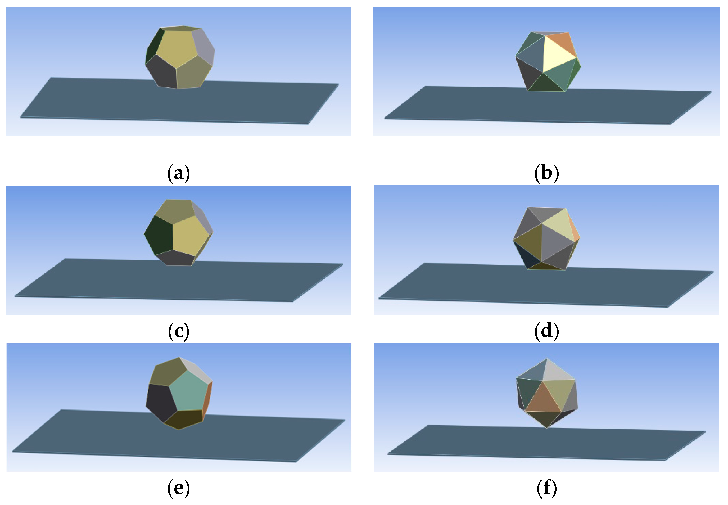
At a collision a mechanical shock is generated. To be able to choose between a dodecahedron and an icosahedron a Finite Element Method (FEM) simulation has been carried out to view a virtual mechanical collision, which has also shock characteristics. As previously mentioned, the inradius of each geometrical object is an important parameter for the supporting volume to the inner electronic parts, etc. In the simulations the dodecahedron and the icosahedron had the same inradius. The thickness of walls was 10 mm and the inradius of the objects was 100 mm. The equal inradius resulted to different masses between the geometrical objects. The length of the edge of an icosahedron was 132.3 mm while the edge of a dodecahedron 89.8 mm. The icosahedron object’s summarized edges were 47.4 % longer than of the dodecahedron object. This meant that the frame for these parts are heavier. Six simulations were performed with the software Ansys Workbench, where the object was defined as a low flow Polypropylene (PP) shell, while the landing area as an aluminum plate. All versions were virtually dropped from 50 mm height with an initial speed of 10 m/s, leading to 10.12 m/s collision speed to a supported 1000 mm × 1000 mm × 5 mm plate. Both geometrical forms were dropped as “face to face”, ”edge to face”, and “vertex to face” in
Figure 1.
On
Figure 1a and
Figure 1b the parallel face to face collision can be seen when one of the body’s faces collided parallel to the plate’s center. On
Figure 1c and
Figure 1d the edge to face collision is shown when one edge of a body collides parallel to the surface of the plate. On
Figure 1e and
Figure 1f one vertex of the body collides to the plate’s surface’s center. At a collision the duration and force need to be compared. The maximal force persisted for a fraction of a millisecond (0.4-0.5 ms). In
Table 2 the duration of collision, the maximal force, and the average forces were compared.
Based on the above-mentioned parameters (duration, maximal- and average forces) we can conclude that dodecahedron performs slightly better, therefore it was chosen for further application.
2.2. Literature Review and Analysis of Possible Materials
An important goal was to produce the inner frame and the unique structural parts in a cheap and simple way, consequently 3D additive manufacturing was chosen as applied technology [
7].
Anycubic 4Max Pro 2.0 Fused Deposition Modelling (FDM) machine was available, with the following primary supported filament materials: Acrylonitrile Butadiene Styrene (ABS), Polylactic Acid (PLA), Thermoplastic Polyurethane (TPU), carbon fiber composite, copper composite and wood composite.
To choose from the primary supported materials, certain conditions had to meet.The chosen material should be user-friendly and should have easy printing characteristics. It must have light density, have optimal strength, a good hardness, non-toxic, not-flammable, and it must let radio waves pass through.
Carbon fiber composite and copper composite filaments contain radio wave insulating materials [
8], which do not allow them to be used for this purpose [
9].
Wood composite has properties always combined with its binding polymer, what is usually PLA (e.g., Polymaker Polywood or extrudr Wood filaments). This material could be applicable, all the same, its price is higher than a normal ABS, PLA or TPU.
3D printing methods evolve at a high rate, therefore parts with woven-fabric-reinforced shape memory polymer composites (SMPCs) with softer structures could be also usable in further developments on safer structures for balloon payloads [
10].
The TPU material is too flexible (it would act like a spring causing additional damage during collision) not to mention that it is more expensive, than normal ABS or PLA material.
ABS has a relative high strength, a relative high impact resistance, and also a higher toughness (e.g., Fillamentum Industrial ABS Extrafill or extrudr’s DuroABS filament). ABS materials have shorter elongation at break compared to TPU, but longer compared to PLA (e.g., Fillamentum Industrial PLA Extrafill filament or extrudr PLA NX2 filament). ABS is usually more expensive than PLA.
PLA is less impact-resistant and it has the shortest elongation at break compared to ABS and TPU.
Based on the pros and contras of the above-mentioned materials, the possibilities can be narrow down to ABS and PLA, as optimal choices.
Simply to state, ABS and PLA have also different printing characteristics.
ABS requires higher temperatures for printing compared to PLA. ABS needs to have a heated print bed usually between 80-110 °C. To improve layer adhesion and also to reduce warping an enclosed workspace is required. PLA can be printed usually on printing bed with a temperature between 15-70 °C. PLA is considered as a cheap material, moreover it is biodegradable thermoplastic, mostly produced from renewable biological resources, so it has less impact on environment compared to ABS.
For further developments the mechanical properties of 3D printed PLA can also be affected by heat treatment [
11]. Research is working also on conductive 3D printed PLA composites, they would lead to less used material, as many parts of a payload could be produced in one piece, this would lead to a lighter weight [
12]. Polymer processing with compression molding and fused filament fabrication (FFF) can affect double electrical percolation threshold in PLA/polycaprolactone (PCL)/graphene nanoplatelet (GNP) composite systems, therefore 3D printing in the future could be used for these kind of production. It needs to be mentioned, that PCL is biodegradable [
13]. PLA based biocomposites can also have also good thermal and mechanical properties [
14]. New components in blends with other polymers can improve the performance. PLA composites take less impact on the environment compared to other polymers like PA6/HDPE nanocomposites [
15]. Studies show that for PLA materials Reactive Extrusion (REX) modified thermoplastic starch particles can be used as bio-based and biodegradable nucleating agent to increase the rate and percent of crystallization, an also improve oxygen barrier properties [
16]. Most of these studies brought us to the conclusion that PLA will be more common in future, so all these possible developments would be a reason to choose PLA, but nonetheless currently this cannot be the final decision.
After the analyses of these data to get final decision ABS, normal PLA and ecoPLA were chosen for 3D printing the parts needed.
2.3. Selection of the Material
Before the complete structure was planned the filament material was chosen. For the frame structure’s pieces Fillamentum ABS Extrafill Metallic Grey, Fillamentum PLA Extrafill Traffic White filament and two versions of ecoPLA filament were bought (a partially translucent and a white colored).
The toughness and strength of printed parts can be controlled by the choice of raster layup. Research with polymer composite blends shows that tensile and compression testing is an option to clear differences between the properties of PLA materials [
17,
18].
The first step before any toughness and strength measurements was to test the printability of the materials. A sample piece was designed in a CAD software for testing purposes. It had a 43.5 mm long, 5.5 mm square section with a 4 mm diameter ball joint at the end. It had a 44 mm × 35 mm × 5.5 mm sized rectangular cuboid part for fixation on a tensile and compression test.
The diameter of the ball joint connection was chosen to be printable, but as small as possible. The parts for testing were printed with 0.1 mm layer height, 0.4 mm shell thickness, 0.5 mm top-bottom.
The shell thickness is at the machines’ minimum, as this is the diameter of the basic nozzle. It needs to be mentioned, that not all materials can be printed in one line’s width wall, because some will produce bad quality or even a failure at the printing.
Fillamentum ABS Extrafill Metallic Grey, two versions of 3DJake ecoPLA filament and the Fillamentum PLA Extrafill Traffic White filament were printed with the Anycubic 4 Max 2.0 machine. The ecoPLA did not provide stable quality as some pieces had failures in shell and layer stability, and surface quality. The pieces printed from Fillamentum ABS Extrafill Metallic Grey and Fillamentum PLA Extrafill Traffic White had much better quality, no failures in shell or layer instability were overserved, therefore they were chosen as materials.
The tests were non-standardized. In order to maintain reproducibility, the parts were printed always in the same printing directions, with the same speeds, temperatures, layer heights, shell thicknesses, top-bottom thickness, and ball joint connection. Two parts were snapped together mechanically to be a ball joint connection. This option was chosen because ball joints have properties for limited range of movement in all directions which is necessary for deformation of the frame and outer shell at the moments of collision.
This ball joints could not just snap together but also apart. Tensile and compression testing was carried out on the ABS and PLA material made parts at the Széchenyi István University’s Material Testing Laboratory with an Instron 5588 universal testing machine.
The tensile measurement was carried out on 5-5 samples, on each 3 times on 4 mm length. At each test the maximal tension (T) force and maximal compression (C) force were measured shown on
Table 3.
The difference between ABS and PLA parts can be clearly seen on
Table 3. At ABS ball joint connections the average tensile force of just 1-7 % higher while the compression force is 2.4-2.6 times higher compared to PLA. A weaker connection and a weaker compression force is better for this purpose. Therefore PLA was chosen for material.
2.4. Design and Manufacture
For a safer payload outer shell a Polyurethane (PUR) flexible porous elastomer was chosen [
4]. It must be added that protein-based biodegradable PUR foams might be also possible in future as an option. For example incorporating soy protein isolate into flexible PUR foam material can lead to the enhancement of resilience, compression and biodegradability together with an increased density [
9].
As payloads can have relative big stiffness, the absorbing frame structure, during collision, must be able to reduce damage. For parts produced with Fused Deposition Modelling (FDM) there are some methods to make them mores resilient without modifying the used material, for example by using inner supporting structures inside the printed parts [
19].
The basic idea was to construct so-called, vertexes” for a frame structure to hold the dodecahedron formed outer shell together. To create such structure, Creo Parametric Computer-Aided Design (CAD) software was used. The vertex parts have ball joints with the ability of carrying a limited range of smooth deformation in all directions. The parts and their connections must be strong enough to hold the whole structure with the mass of the shell and the inner electronic parts.
The inner frame pieces were planned in a CAD software The parts were produced with an Anycubic 4Max Pro 2.0 FDM machine by the use of PLA material. The vertex parts have 3 arms separated at an angle of 120°. These arms are 45 mm long and they stretch from the middle vertical axis to the midpoint of the ball joint connection. The diameter of the ball joints is 4 mm. The layer height of all parts was 0.1 mm, with a single line 0.4 mm shell thickness, and 0.5 mm top-bottom height.
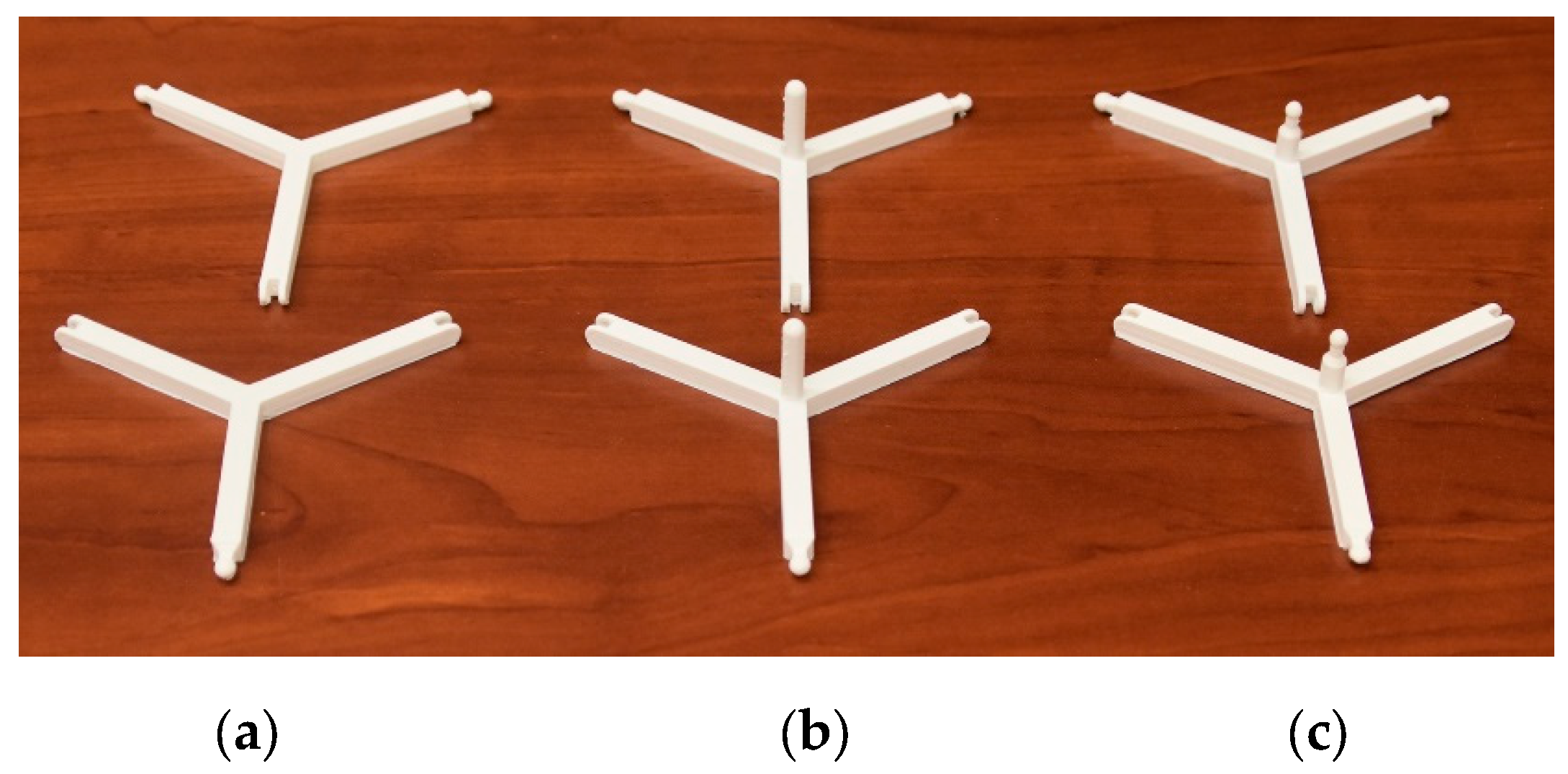
On
Figure 2 the printed vertex parts are shown. On
Figure 2a frame parts without any protrusion components are visible. These are the normal frame parts. On
Figure 2b parts are shown with protrusion components, or pillars. These pillars support the inner payload (e.g., electronics) from the downside as later described. On
Figure 2c the parts have protrusion pillars, with a sphere for a ball joint. These parts have a ball joint connection with a pentagonal ring downside as later described.
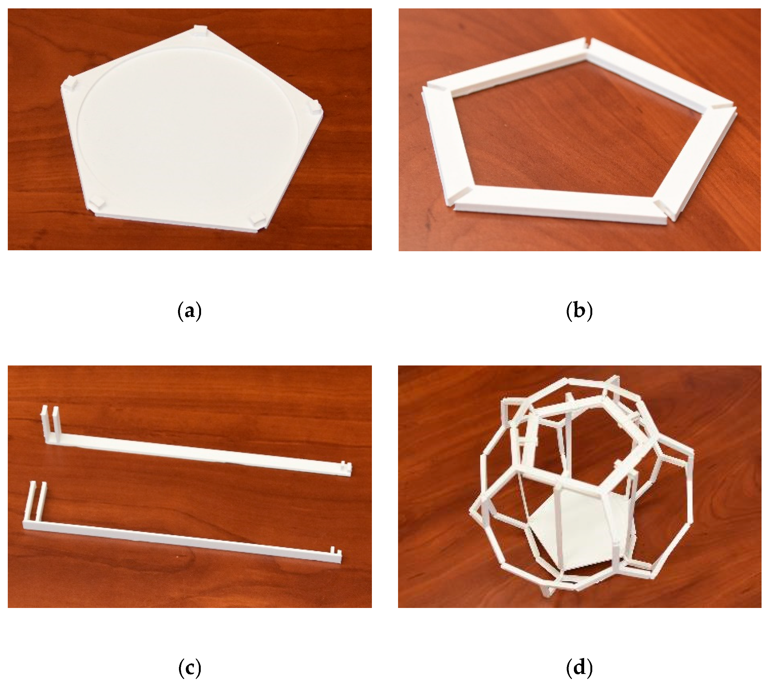
This previously mentioned pentagonal ring is shown on
Figure 3a. This pentagonal ring is fixed with ball joint to the frame. It also fixes the inner payload with the help of long supporting parts shown on
Figure 3b. The fixation to the downside of the inner parts (e.g., electronic inner payload) is made by a flat part shown on
Figure 3c.
After all the needed parts were manufactured the whole frame were built together. On
Figure 3d the whole frame structure is shown. The frame looks like a truncated polyhedron, but after adding the previously mentioned outside PUR foam shell it becomes a regular dodecahedron.
2.5. Low Air Pressure Test with Printed Parts and with the Complete Model
Two low air pressure tests were carried out to look for possible deformation. These tests were performed by expanding the air inside the parts. One test was carried out only with the parts of the frame structure, and one with the complete new model.
Both tests were performed with an air pressure simulating machine in the Packaging Laboratory at the Széchenyi István University. The tested pieces were placed inside the machine on an A3 sized paper with 10x10 mm sized black and white squares. A camera and a lamp were placed above them. The camera took photos every 5 second.
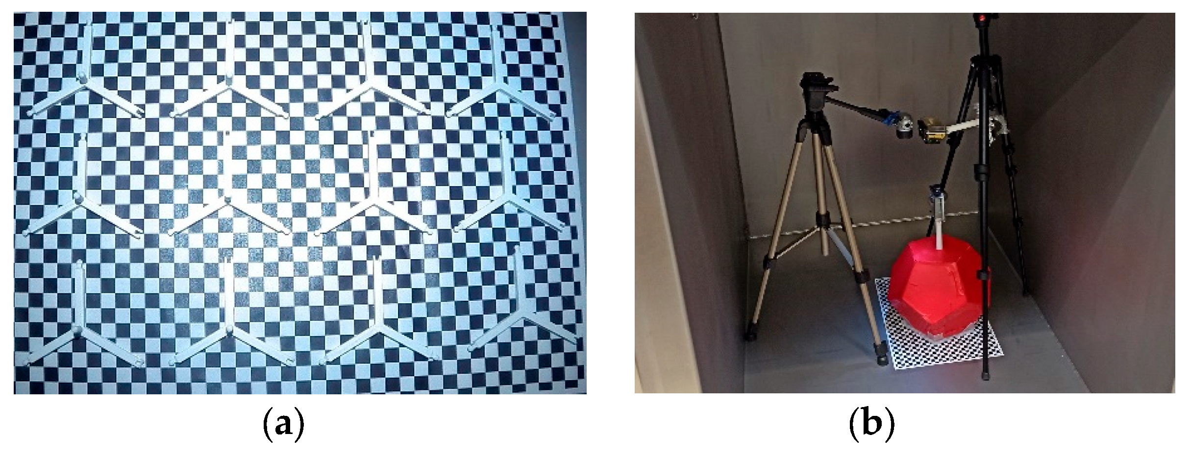
The purpose of the first test was to reveal if the parts of the frame structure would expand at low air pressure. As shown on
Figure 5a, 12 samples (6 normal parts, 6 parts with pillars) were placed inside the machine. Test begun at pressure of 1003 hPa and 80 hPa was reached (which contributes to the air pressure of 17.6 km altitude) in 24 minutes. None of the samples showed any deformation. Most probably walls of the parts have microscopic gaps where air can leave.
The purpose of the second test was to reveal if the whole new model would expand at low air pressure. As shown on right side of
Figure 5b one model was placed inside the machine. Test begun at pressure of 1001 hPa and 80 hPa was reached in 24 minutes. Similarly, the new model did not show any deformation either. Neither the frame, nor the foam shell deformed.
2.6. Freezing Test with the Finished Model
The heat insulation was tested inside a climate chamber. The tests were performed at Material Testing Laboratory (Széchenyi István University) with an ACS Angelantoni Testtechnologies climate chamber to measure the possible decrease of the temperature inside the shell. The test system could reach -40 °C, which is above the usual temperatures in the flight altitudes of these kind of balloons. For example, the International Civil Aviation Organisation Standard Atmosphere’s (ICAO) temperature value is 15 °C for 0 km ground level, -56.5 °C for 11 km to 20 km geopotential altitude, -36.1 °C for 35 km geopotential altitude[
20]. It must be noted that the ICAO and ISO (International Organization for Standardization) Standard Atmospheres are identical.
Table 4 shows the thermal conductivity of air at different altitudes and temperatures [
20,
21].
The room temperature, and the temperature of the model was 22 °C at the beginning of the test. The chamber together with the model was cooled down, in 20 minutes, from 22 °C to -40 °C. -40 °C temperature was maintained for 3 hours, and at the end of this period the temperature sensor, inside the structure, measured -3 °C. After the cooling test the chamber was warmed up to 22 °C.
The time (3) until the core of the model reaches -3 °C, at any altitude, can be calculated from Newton’s law of cooling (2).
T(t) – measured temperature
T0 – initial temperature of the object
Ts – surrounding temperature
k – thermal conductivity
t – time
Table 4 shows the ratio between an altitude’s and ground level’s effectiveness based on equation (3). It also shows a calculated estimated time based to reach -3 °C at each altitude’s parameters. In addition it is visible that a theoretical flight time of 2.49 h at 25 km geopotential altitude would have the same effect on our tested structure as the 3 h cooling at ground level. The test proved that a flight with such duration and temperature would not affect the structure.
2.7. Drop Test with the Complete Model
After the planning and realization, a drop test was carried out with the purpose to measure the collision force of the two different payloads (the dodecahedron design and the rectangular cuboid design). The test was performed at the Packaging Laboratory. The payloads were dropped on a 20 mm × 800 mm × 520 mm sized (height × length × width) steel plate, while the impact forces were measured, in each case five times, by pressure cells with a maximum accuracy of 0.05%.
It must be mentioned that shock damage of a package has 3 main factors: the peak acceleration, the change of velocity and the duration of the whole process.
At this drop test the analysed factors were the measured force and the duration. As known by Newton’s second law, the force is equal to mass multiplied by acceleration. So by analysing force and duration the needed information can be obtained.
To get the needed information about the collision process Savitzky-Golay filtering method and RStudio software (with R programming language) were used to process the data [
22].
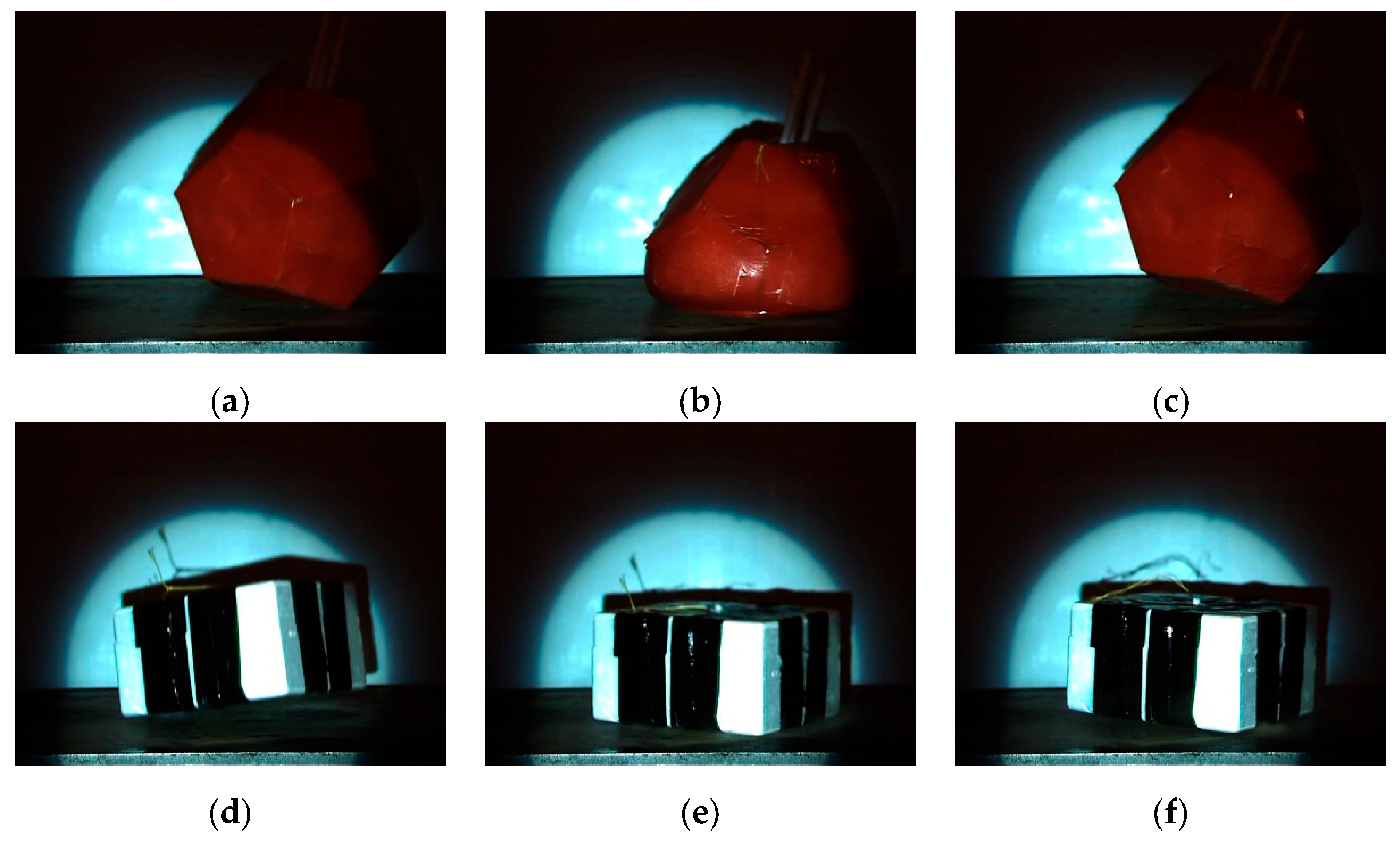
Video recordings were also done for the drop tests 3 times in each case. 2000 fps with 1280×1024 pixel resolution was taken with an iX i-SPEED 3 high-speed camera with a Tamron AF 28-300mm f/3.5-6.3 XR Di LD Aspherical Macro objective. Deformations can be visually analysed in 0.5 ms time steps.
The new type of payload package and a rectangular cuboid payload package were dropped from 4.8m height. The new dodecahedron shell and the classic cuboid box had an extra weight inside as a simulation of electronics or other inner parts. Its mass was 595g. It should be added that the dodecahedron and the box themselves had different masses, therefore their total mass were not identical. The box was made of expanded polystyrene (EPS). The new dodecahedron payload had a soft Smooth-On FlexFoam-iT! III Polyurethane foam (PUR foam) outer shell which was chosen in a previous work [
4].
The box shell had dimensions of 134±2 mm × 234±2 mm × 185±1 mm (height × length × width), a wall thickness of 17.5±0.5 mm a mass of 285-305 g, with a final mass of 880-900 g. Its impact speed was 8.6 m/s. The biggest surface area (the downside) was the colliding face.
The new type, dodecahedron shell has an edge length of a = 100 mm. A circumsphere radius R = 140.1 mm and a wall thickness of 21 mm. The final mass of the dodecahedron body was 1100 - 1200 g.
The circumsphere radius can be calculated by the next formula, where “a” is the length of edge [
23].
It needs to be mentioned, that both the box and dodecahedron package were dropped with an exactly balanced mass centre, so the slight differences at the impact were most probably caused by other factors, such as the opening of the gripper. It can be hypothesized that the gripping did not open exactly symmetric in time, and it led to a small twisting, which increased during the fall. It needs to be stated that in real life atmospheric conditions, together with the balloon and the parachute always cause that the payload packages begin to swing and twist as a pendulum before the moment of impact. Consequently, this means that the laboratory drop test demonstrated real-life situation.
3. Results and Discussion
On
Figure 6. two graphs can be seen. The 1st line is a dodecahedron’s drop test, the 2nd line is the drop test of a rectangular cuboid. It can be clearly seen, that a rectangular cuboid’s collision results higher force and shorter duration compared to a dodecahedron’s collision.
Table 5 shows the processed measured data of the separate drop tests. After the end of the curves the force data is under zero, due to the generated shock, which is the resonance on the target steel plate. By inspecting the average of the maximal forces it could be concluded that the dodecahedron payload package caused 43% less force under a 78% longer collision time. This means that even though a heavier dodecahedron structure has higher impulse and pressure, due to its softness, it would result in less damage compared to the more rigid rectangular cuboids (with EPS material) since it transmits less impact force to the target with the same inner payload mass.
By analysing the frames it can be said that all parts of the collision can be separately seen.
Figure 7a shows a dodecahedron formed payload’s first contact with target plate. On
Figure 7b the maximal deformation of the dodecahedron payload is shown. On
Figure 7c the dodecahedron shaped payload left the target plate.
Figure 7d a rectangular cuboid shaped body’s first contact with target is shown. On
Figure 7e the full contact with target surface is shown. On
Figure 7f the rectangular cuboid left the target plate.
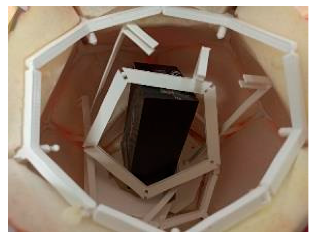
On
Figure 8 the inside of a payload with the extra weight can be seen after a drop test. The energy absorption of a movable and also breakable frame structure with its soft outer layer absorbs more impact energy, therefore it potentially deforms more. The force of impact is distributed inside a larger area and over a longer duration, which reduces the peak force.
To make our results more realistic, a real fligh test was also carried out with the new type of payload on the 30th of October 2021. Its flight lasted for 1 h 37 min. The test started at Hegyhát Observatory in Hegyhátsál (Hungary) whilst its landing site was at Potyon (Hungary). The maximal reached altitude was 27465 m, while top speed (293 km/h) was achieved at 25378 m altitude. It must be stated that the mass of the payload was 1.6 kg, whereas its descent speed was 2.8 m/s in the last minute before touchdown.
Its primary tracking was performed with 3 reprogrammed Vaisala RS-41-SG radiosondes for 3 frequencies in APRS-tracking (432.500MHz, 432.775MHz, 432.900MHz). For APRS-tracking HA1NX, the official radio amateur call sign of N. Hegyi was used. Tracking data was transmitted in every 60 seconds on each frequency.
During the flight, temperature data was also transmitted by the tracking system, which registered a minimal temperature of 4 °C on one side of the radiosonde, while 10 °C on the other side of the radiosonde. This data supports the estimated values in
Table 4.
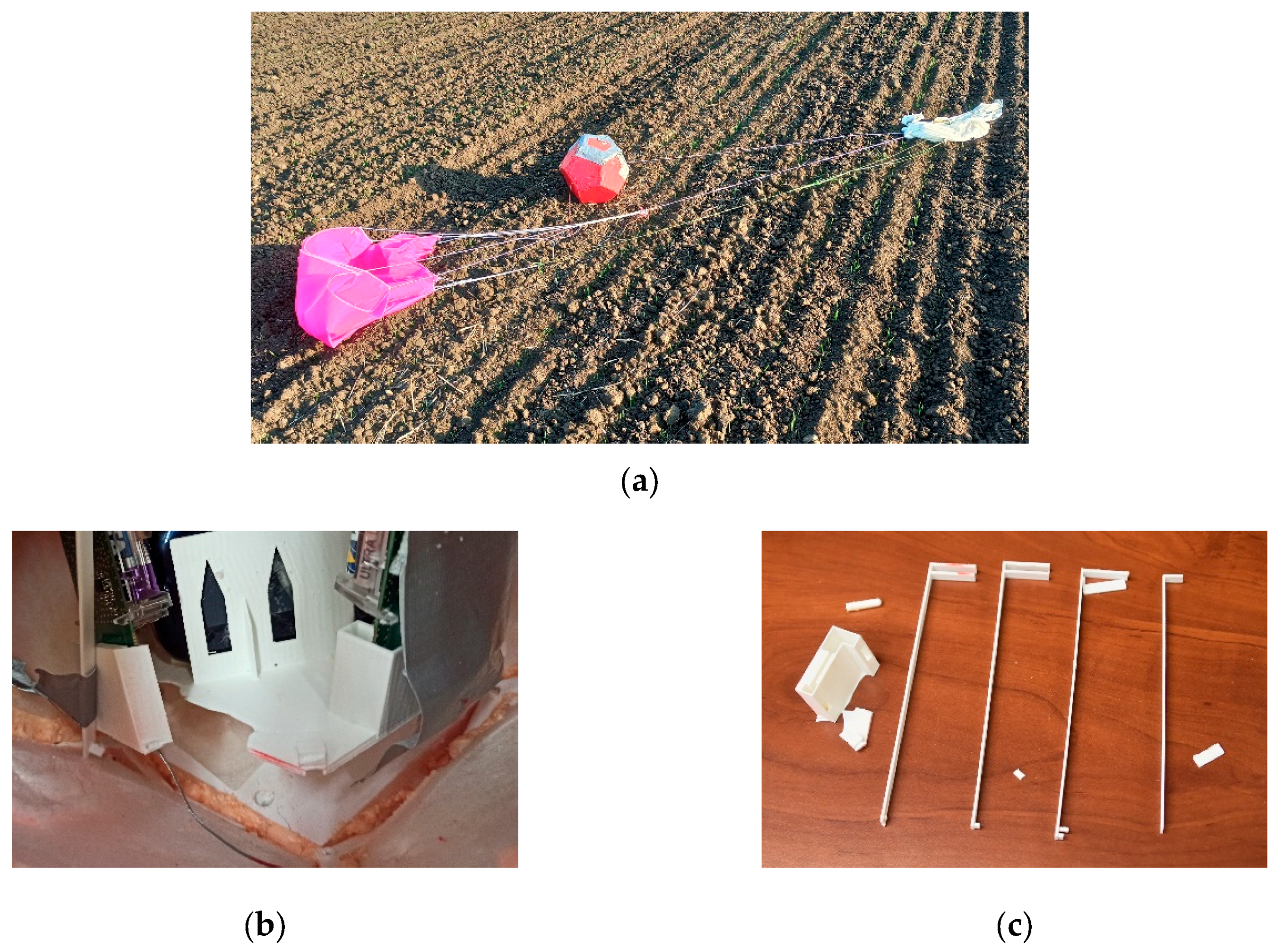
The payload’s inner downside flat plate was modified to keep the instruments in place for flight tracking. The modified part was planned to be able to fall apart in vertical direction at the impact to the ground. The payload had performed well at its flight. It had survived the extreme conditions, such as high wind speed or low air pressure.
Figure 9a shows the payload after touchdown.
Figure 9b demonstrates the bottom part which is bendt and broken as planned. On
Figure 9c the broken supporting inside parts are shown.
4. Conclusions
The development and testing have led to a new usable option to build safer structures for payload package of light unmanned free balloons. This novel payload has the form of a dodecahedron and made out of PLA. The form and the material were selected by a rigorous analysis and experimental tests.
First, the selection of geometric design was done through data analyses. Eight possible geometric forms were investigated by finite element simulations, which clarified that the dodecahedron form is the most suitable option for a new type of payloads with regard to light unmanned free balloons. This choice was made on the basis that the dodecahedron form yielded the lowest impact forces.
Second, the selection of material was done by the basis of tensile tests where two possible materials were examine PLA and ABS. Since the purpose of the inner frame is to absorb impact energy by carrying out plastic deformation and partial disintegration, PLA was preferred over ABS due to its lower compression abilities.
When the both the geometrical form and the material were selected and several complete models were manufactured with additive technologies, dropt tests were performed. It was deducted that the newly introduced dodecahedron form has could significantly elongate the impact duration (by 78%) which resulted in lower (41%) impact force. The high-speed camera tests has validated the existence of the elongated plastic deformation with this kind of geometry-material couple.
As a final proof for the new payload, a real life drop test and post-hoc visual analysis were carried out where it was validated that the model could protect the inner electronics.
