Submitted:
18 March 2024
Posted:
22 March 2024
You are already at the latest version
Abstract
Keywords:
1. Introduction
- 1.
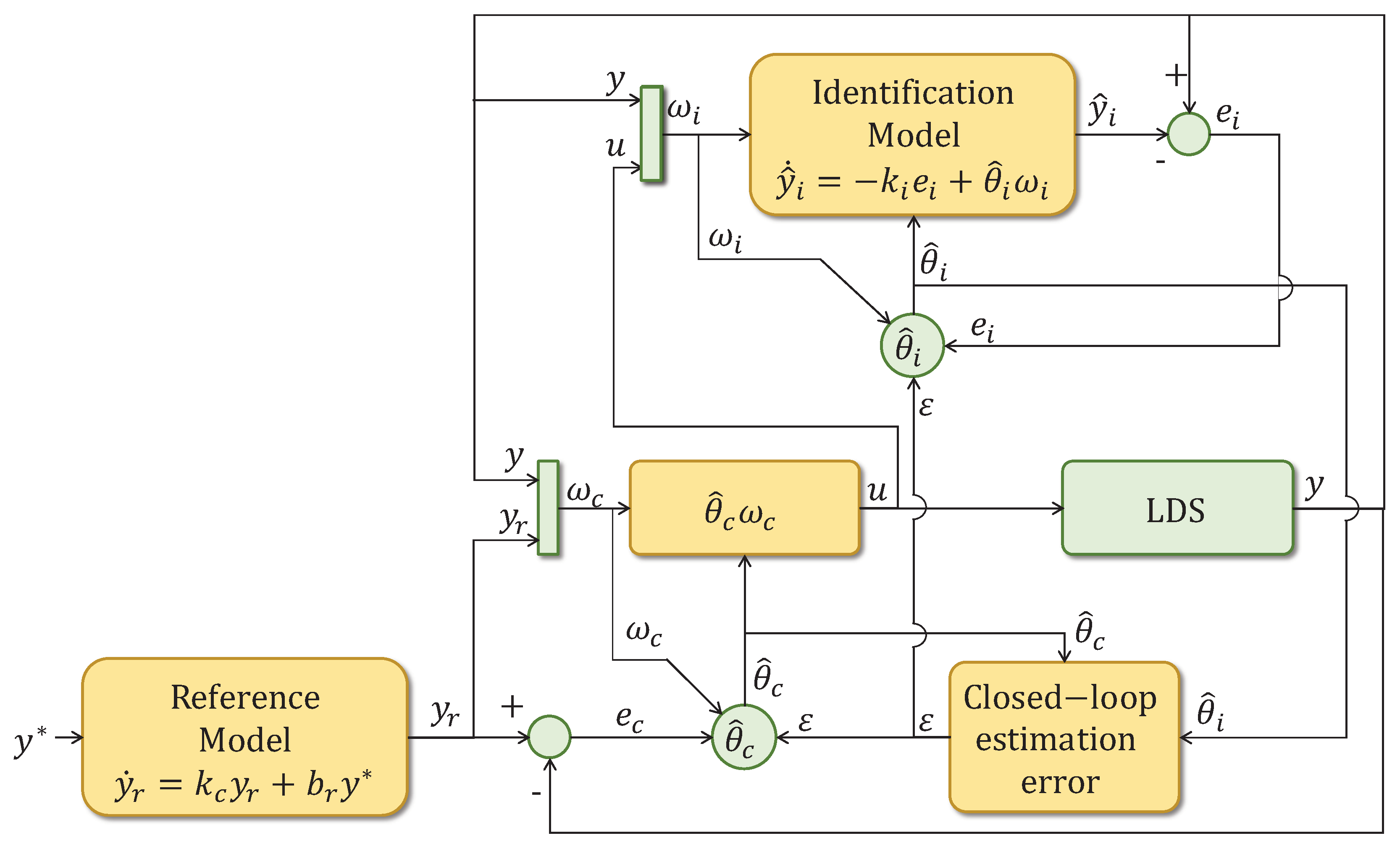
- Proposing a novel CAPBC. The paper proposes a novel CAPBC technique that extends the existing DAPBC scheme from [30]. Compared to previous works [31,32,33], the CAPBC can handle a wider range of MIMO NLDS with bounded external disturbance and unmodeled dynamic. In contrast to [34,35,36,38], the proposal considers the estimation error originally proposed by [31,32,33].
- 2.
- Implementing a SISO CAPBC angular speed control. The proposed technique is applied to the outer loop of an IFOC for IMs, where it controls the angular speed. Implementing the CAPBC is more complex than the DAPBC from [30] but improves performance by incorporating online parameters adaptive estimation. The controller does not require knowledge of the motor load mechanical parameters, unlike the PIC.
- 3.
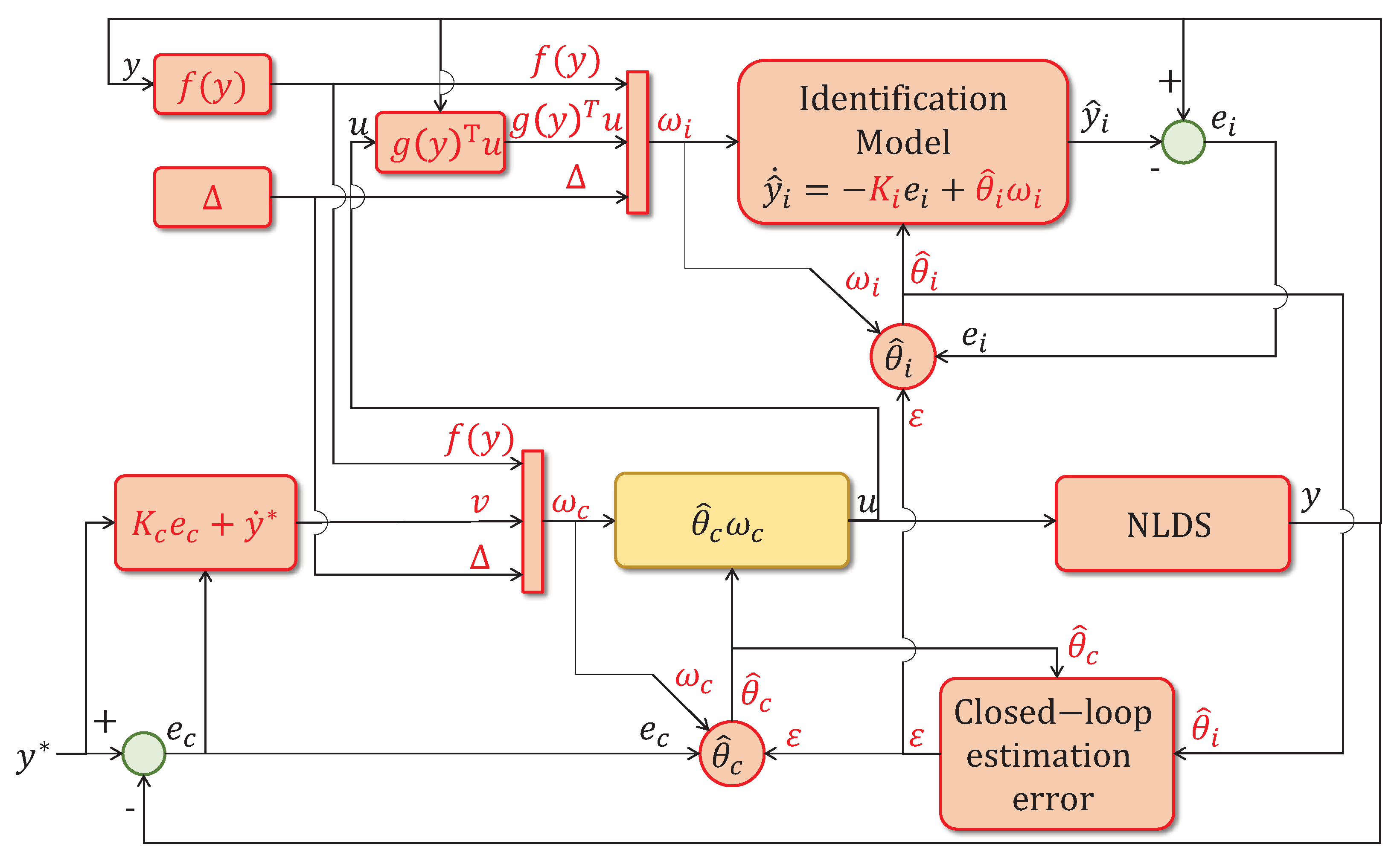
- Implementing a MIMO CAPBC d-q axis current control. The proposed technique is also applied to the inner loop of an IFOC for IMs, where it controls the stator current vector components. In contrast to previous works [34,35,36,38], the CAPBC can handle systems with an utterly unknown B with a known control direction - UCD, which is the case for IMs.
- 4.
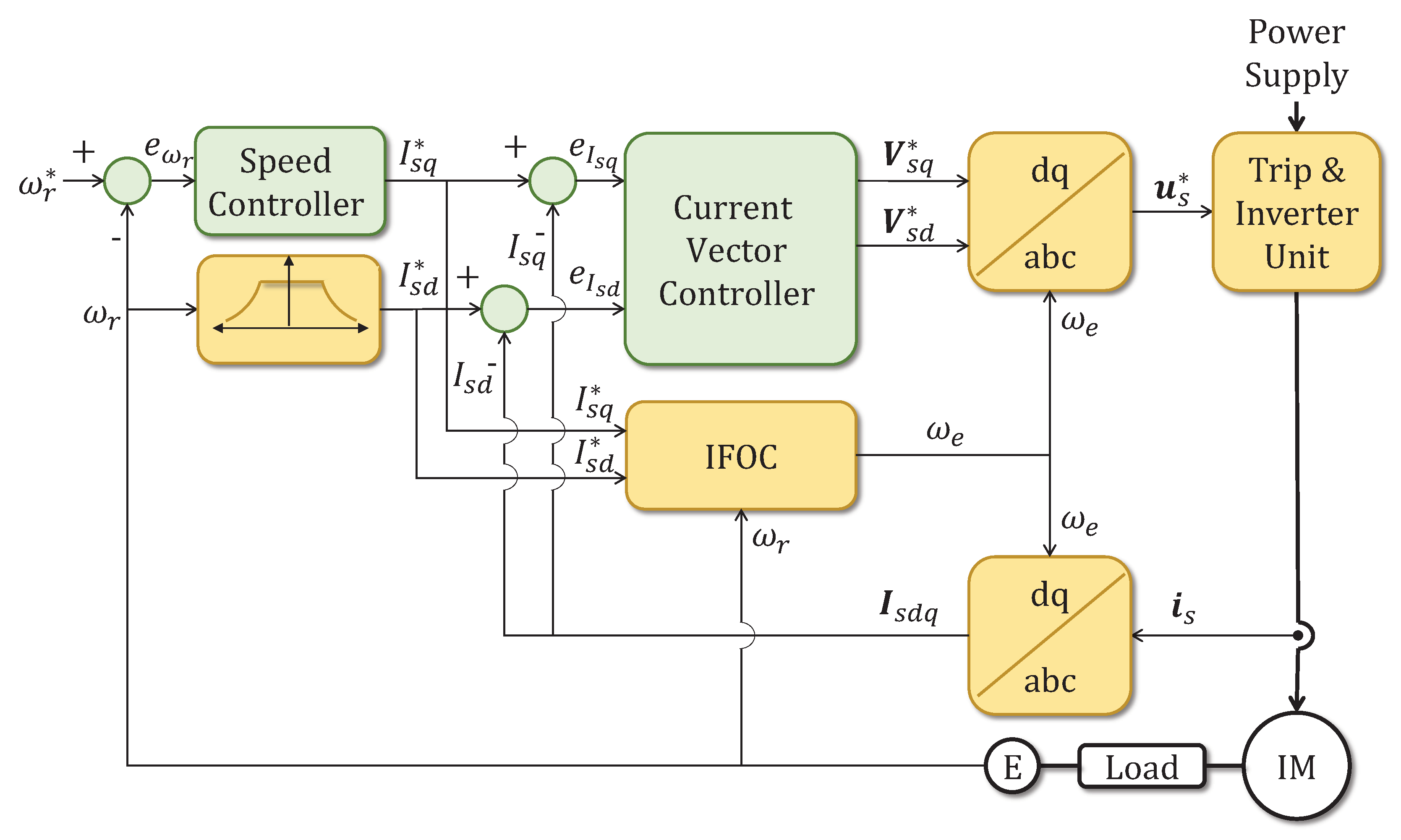
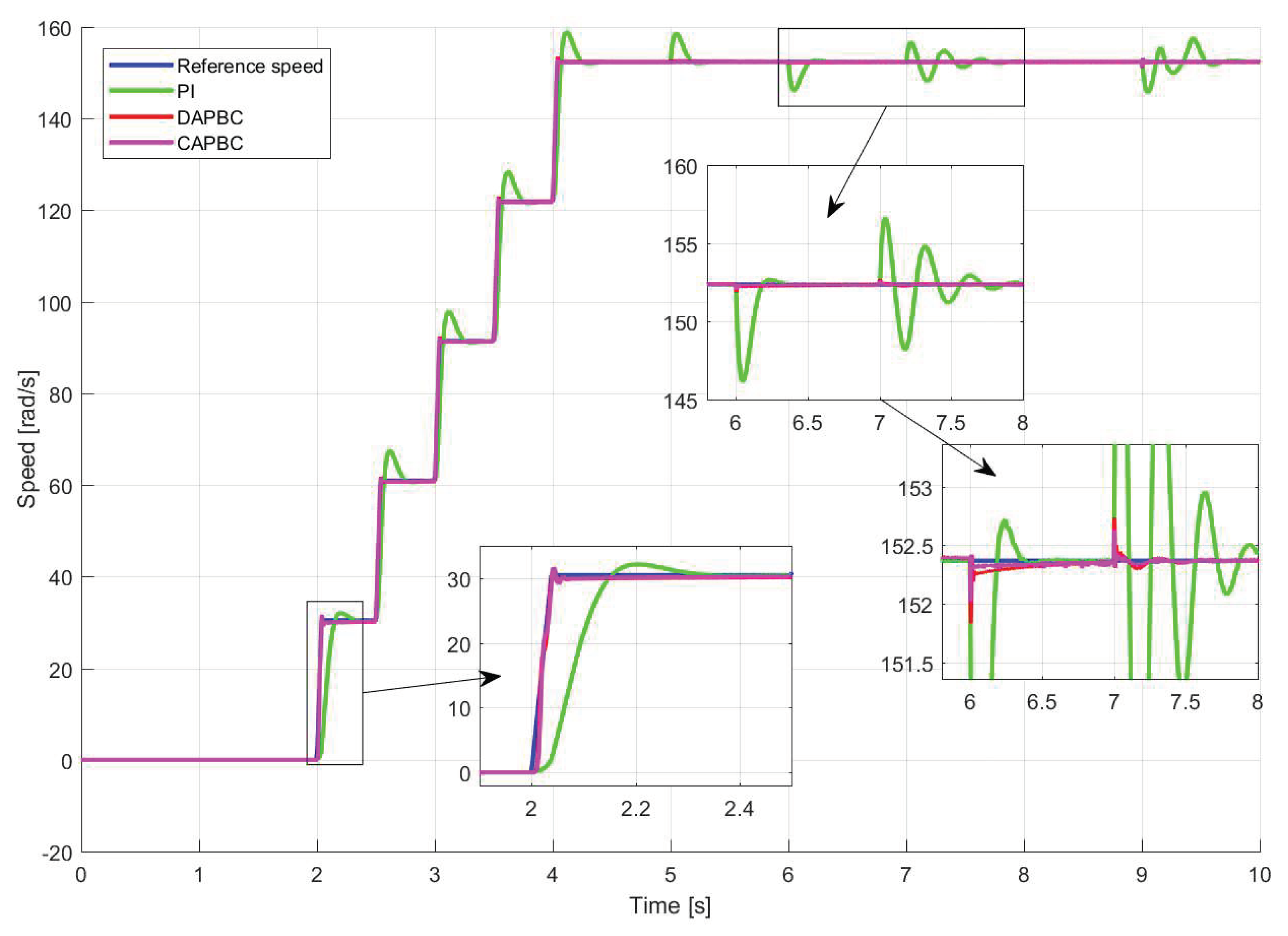
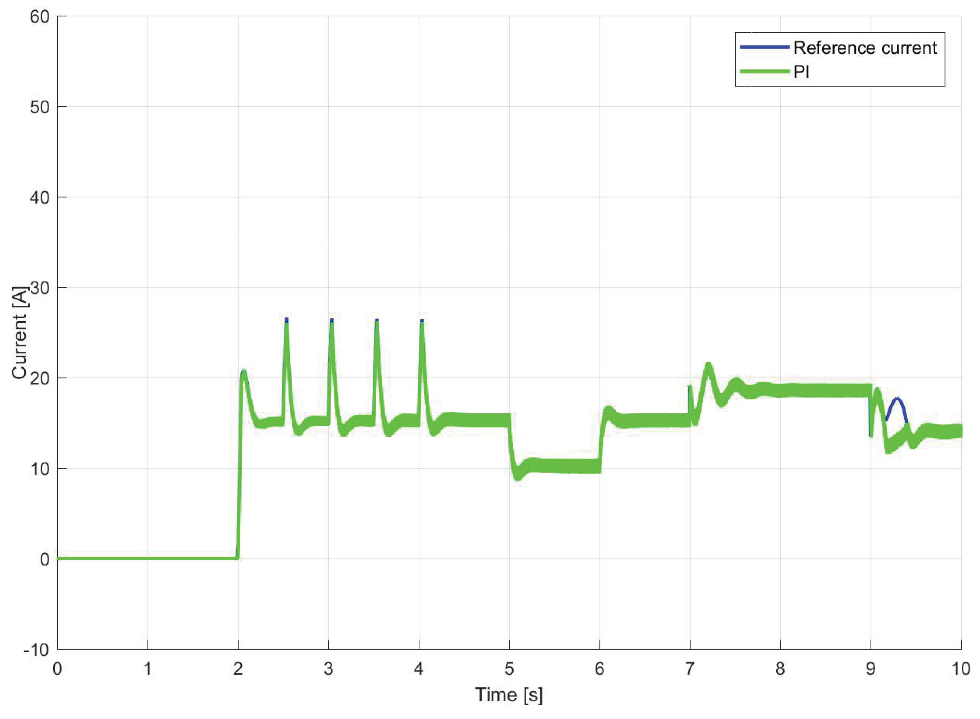
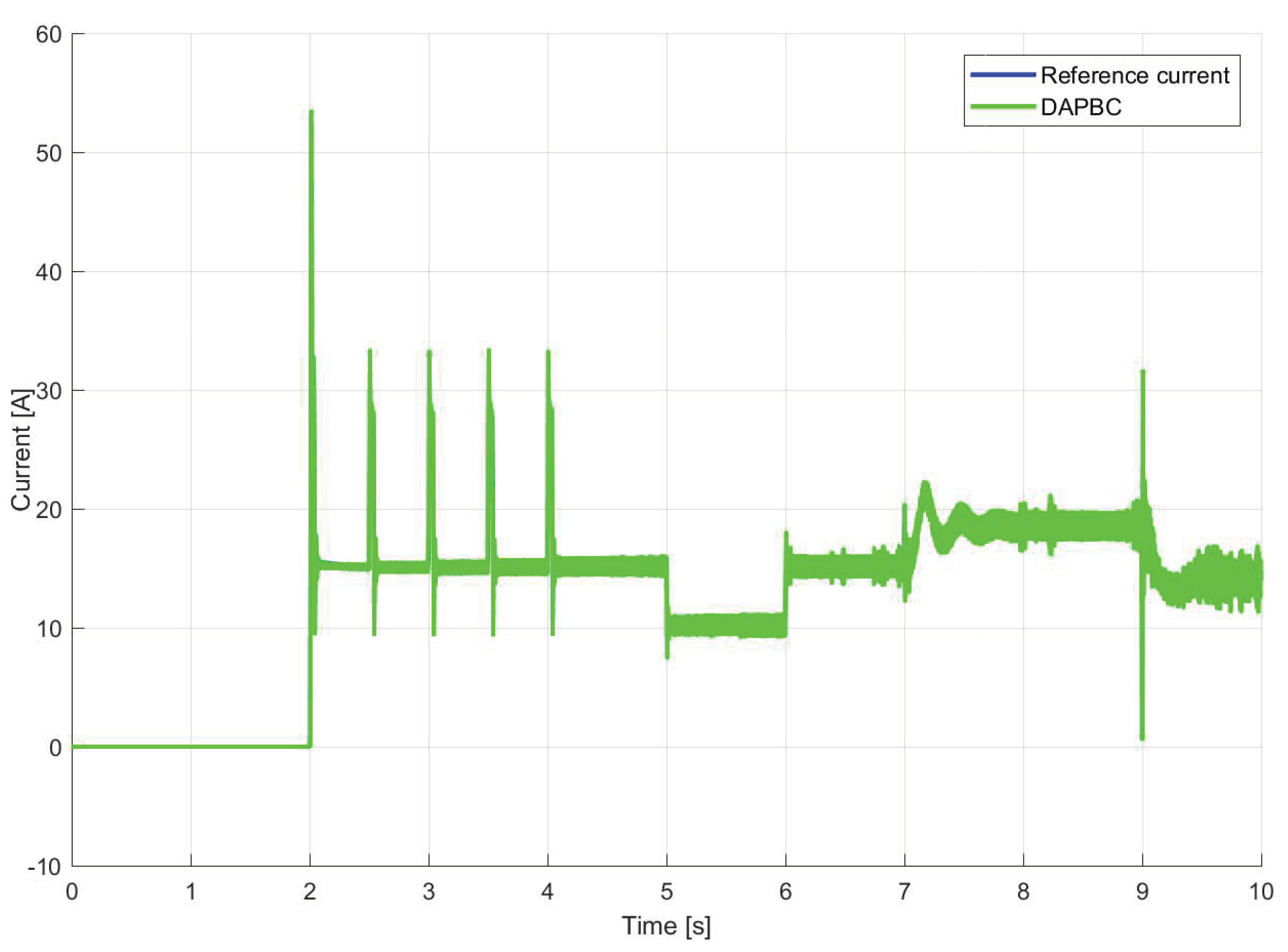
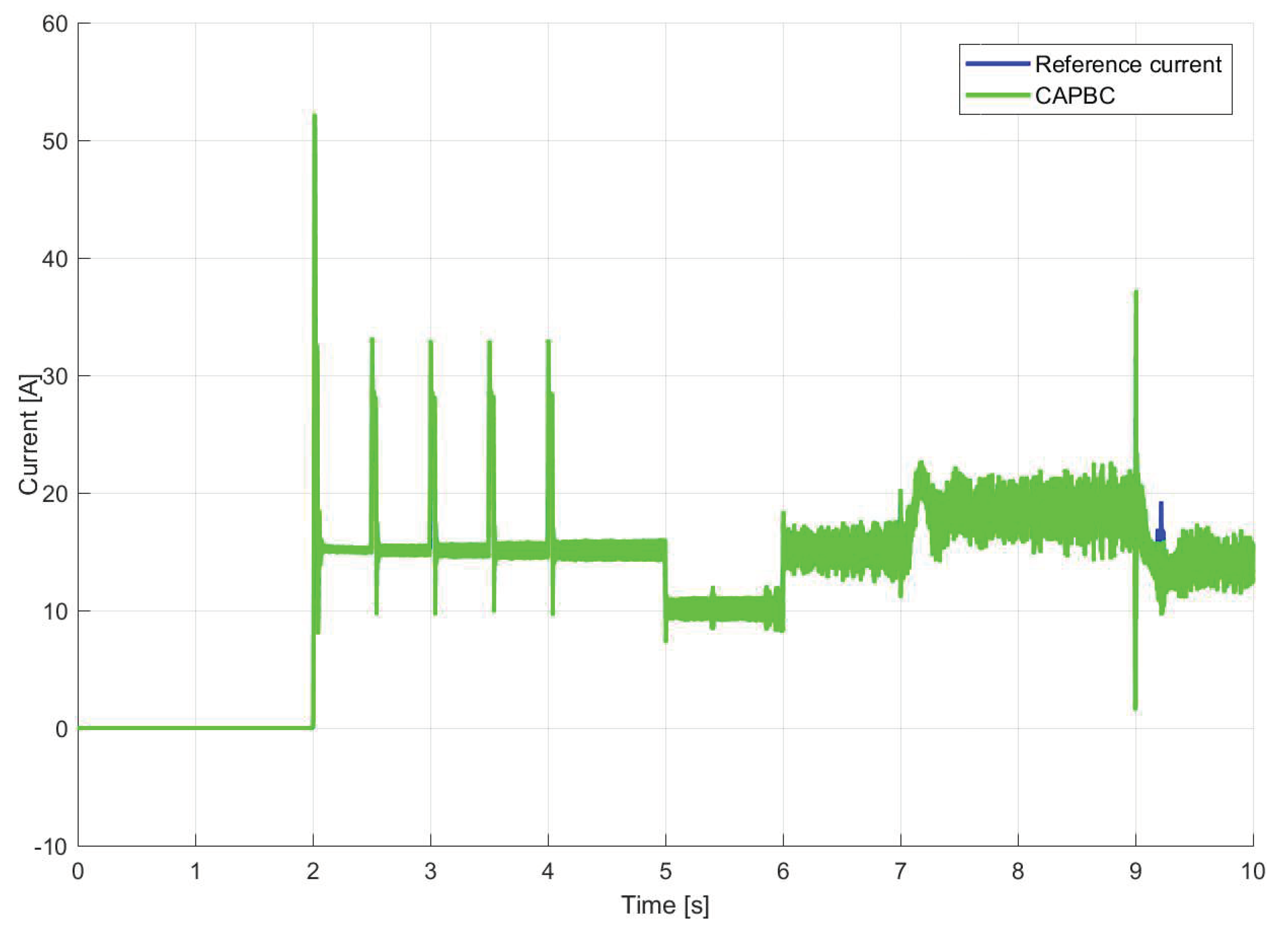
- Presenting comparative experimental results. The paper presents experimental results that compare the proposed CAPBC, DAPBC, and PIC techniques in an IFOC scheme for IMs. These tests include more changes than the ones considered in previous studies [28,29,30]. Specifically, the tests consider changes in angular speed reference, parameters that affect field orientation, and load torque. The results demonstrate that the proposed technique is effective and outperforms DAPBC and PIC techniques.
2. Preliminaries
2.1. d-q IM Dynamic Model and IFOC Diagram
2.2. PIC adjustment
2.3. CMRAC basis to be expanded for APBC
3. Proposed CAPBC
4. Experimental Results
- 1.
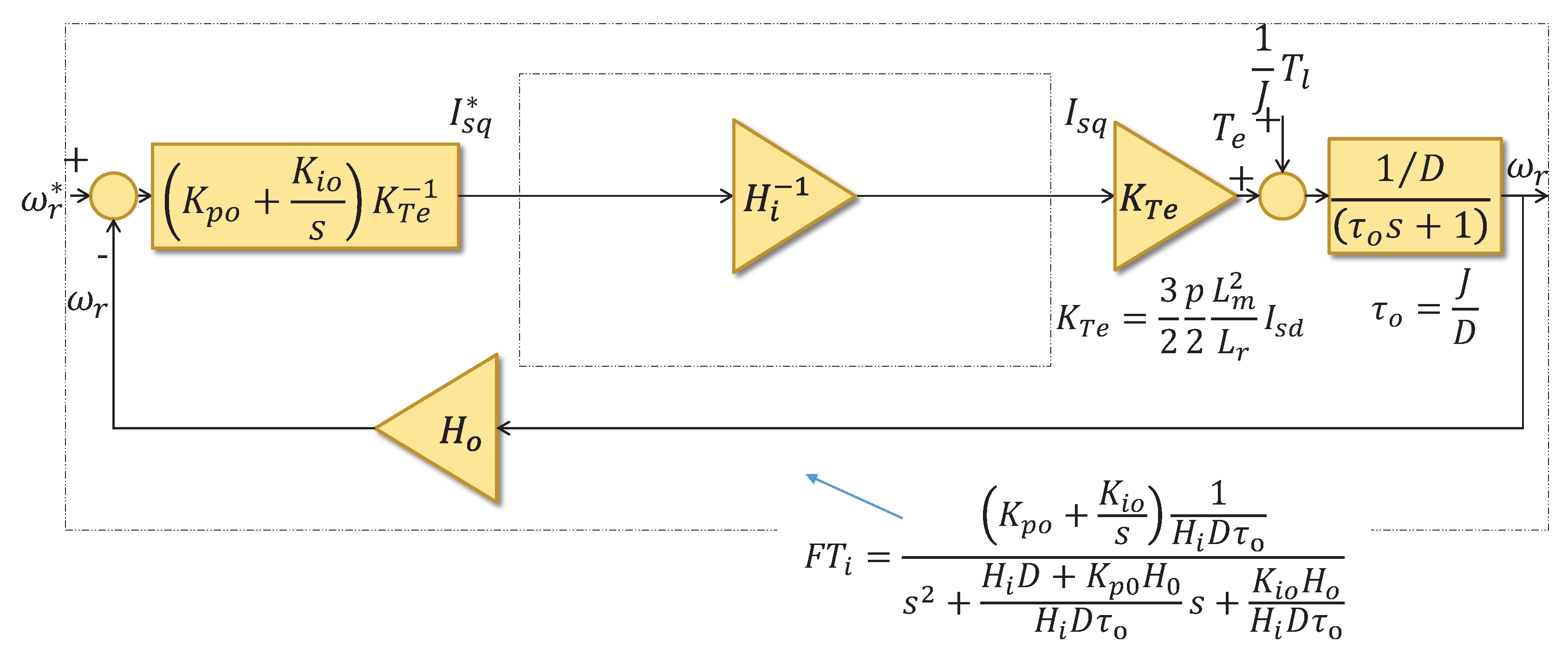
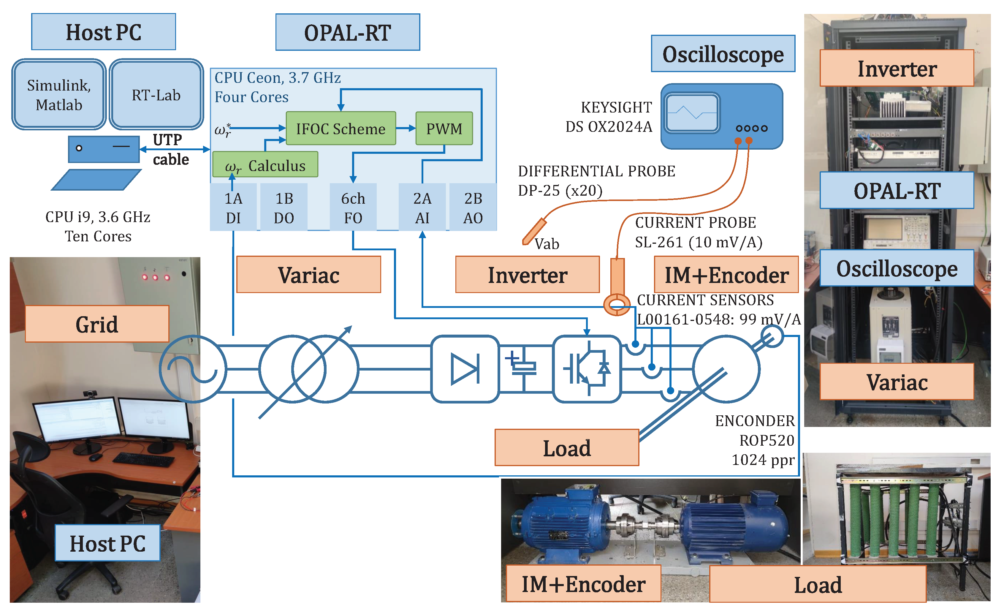
- PIC (4) and (5). These controllers were adjusted as described in the Section 2.2 and using the motor-load parameter values from [16](Tables III, IM 2). that followed the IEEE standard 112A, including DC injection, locked rotor, and free load [13](Section 5.9).
- 2.
- 3.
- Proposed CAPBC from Theorem 1. It also uses a SISO controller and a MIMO controller both as in (10).
5. Conclusions
Author Contributions
Funding
Conflicts of Interest
6. IFOC Method Basis
7. PIC Adjustment

8. CAPBC Stability Proof
References
- Ivanov-Smolenskij, A.; Kuznecov, B. Electrical machines: Vol. 1; Number v. 3, Mir, 1983.
- Hannan, M.; Ali, J.A.; Mohamed, A.; Hussain, A. Optimization techniques to enhance the performance of induction motor drives: A review. Renewable and Sustainable Energy Reviews 2018, 81, 1611–1626. [CrossRef]
- Travieso-Torres, J.C.; Contreras-Jara, C.; Diaz, M.; Aguila-Camacho, N.; Duarte-Mermoud, M.A. New Adaptive Starting Scalar Control Scheme for Induction Motor Variable Speed Drives. IEEE Transactions on Energy Conversion 2021, 37, 729–736. [CrossRef]
- Depenbrock, M. Direkte selbstregelung (DSR) für hochdynamische drehfeldantriebe mit stromrichterspeisung. etz-Archiv 1985, 7, 211–218.
- Vas, P. Sensorless vector and direct torque control. (No Title) 1998.
- Hasse, K. Zur Dynamic Drehzahlgeregelter Antriebe mit stromaschinen, techn, Hoschsch. Darmstadt. PhD thesis, Dissertation, 1969.
- Blaschke, F. The principle of field orientation as applied to the new transvector closed-loop control system for rotating-field machine. Siemens review 1772, 34, 217–220.
- Desoer, C.; Lin, C.A. Tracking and disturbance rejection of MIMO nonlinear systems with PI controller. IEEE Transactions on Automatic Control 1985, 30, 861–867. [CrossRef]
- Ogata, K. Ingeniería de control moderna; Pearson Educación, 2003.
- Sengamalai, U.; Anbazhagan, G.; Thamizh Thentral, T.; Vishnuram, P.; Khurshaid, T.; Kamel, S. Three phase induction motor drive: a systematic review on dynamic modeling, parameter estimation, and control schemes. Energies 2022, 15, 8260. [CrossRef]
- Amaral, G.F.V.; Baccarini, J.M.R.; Coelho, F.C.R.; Rabelo, L.M. A high precision method for induction machine parameters estimation from manufacturer data. IEEE Transactions on Energy Conversion 2020, 36, 1226–1233. [CrossRef]
- Perin, M.; Pereira, L.A.; Silveira, G.B.; Haffner, S. Estimation of the parameters for multi-cage models of induction motors using manufacturer data and PSO. Electrical Engineering 2023, pp. 1–19. [CrossRef]
- Engineers, E.; Board, I. IEEE Standard Test Procedure for Polyphase Induction Motors and Generators. IEEE Standards Boards Std 112-2017 (Revision of IEEE Std 112-2004) 2018, pp. 1–115. [CrossRef]
- Yoo, J.; Lee, J.H.; Sul, S.K. FEA-Assisted Experimental Parameter Map Identification of Induction Motor for Wide-Range Field-Oriented Control. IEEE Transactions on Power Electronics 2023. [CrossRef]
- Véliz-Tejo, A.; Travieso-Torres, J.C.; Peters, A.A.; Mora, A.; Leiva-Silva, F. Normalized-Model Reference System for Parameter Estimation of Induction Motors. Energies 2022, 15, 4542. [CrossRef]
- Travieso-Torres, J.C.; Lee, S.S.; Veliz-Tejo, A.; Leiva-Silva, F.; Ricaldi-Morales, A. Self-Commissioning Parameter Estimation Algorithm for Loaded Induction Motors. IEEE Transactions on Industrial Electronics 2024, pp. 1–11. [CrossRef]
- Ioannou, P.A.; Sun, J. Robust adaptive control; Vol. 1, PTR Prentice-Hall Upper Saddle River, NJ, 1996.
- Åström, K.J.; Wittenmark, B. Adaptive control; Courier Corporation, 2008.
- Narendra, K.; Annaswamy, A. Stable Adaptive Systems; Dover Books on Electrical Engineering, Dover Publications, 2012.
- Tiwari, M.; Prazenica, R.; Henderson, T. Direct adaptive control of spacecraft near asteroids. Acta Astronautica 2023, 202, 197–213. [CrossRef]
- Artuc, M.B.; Bayezit, I. Robust adaptive quadrotor position tracking control for uncertain and fault conditions. Proceedings of the Institution of Mechanical Engineers, Part G: Journal of Aerospace Engineering 2023, 237, 3172–3184. [CrossRef]
- Wang, Y.; Shen, C.; Huang, J.; Chen, H. Model-free adaptive control for unmanned surface vessels: a literature review. Systems Science & Control Engineering 2024, 12, 2316170. [CrossRef]
- Liu, Z.; Zhao, Y.; Zhang, O.; Chen, W.; Wang, J.; Gao, Y.; Liu, J. A Novel Faster Fixed-Time Adaptive Control for Robotic Systems With Input Saturation. IEEE Transactions on Industrial Electronics 2023.
- Burghi, T.; Iossaqui, J.; Camino, J. A general update rule for Lyapunov-based adaptive control of mobile robots with wheel slip. International Journal of Adaptive Control and Signal Processing.
- Mirzaee, M.; Kazemi, R. Direct adaptive fractional-order non-singular terminal sliding mode control strategy using extreme learning machine for position control of 5-DOF upper-limb exoskeleton robot systems. Transactions of the Institute of Measurement and Control 2024, p. 01423312231225605. [CrossRef]
- Abubakr, H.; Vasquez, J.C.; Mohamed, T.H.; Guerrero, J.M. The concept of direct adaptive control for improving voltage and frequency regulation loops in several power system applications. International Journal of Electrical Power & Energy Systems 2022, 140, 108068. [CrossRef]
- Travieso-Torres, J.C.; Ricaldi-Morales, A.; Véliz-Tejo, A.; Leiva-Silva, F. Robust Cascade MRAC for a Hybrid Grid-Connected Renewable Energy System. Processes 2023, 11, 1774. [CrossRef]
- Karami-Mollaee, A.; Barambones, O. Higher Order Sliding Mode Control of MIMO Induction Motors: A New Adaptive Approach. Mathematics 2023, 11, 4558. [CrossRef]
- Çavuş, B.; Aktaş, M. A New Adaptive Terminal Sliding Mode Speed Control in Flux Weakening Region for DTC Controlled Induction Motor Drive. IEEE Transactions on Power Electronics 2023.
- Travieso-Torres, J.C.; Duarte-Mermoud, M.A.; Díaz, M.; Contreras-Jara, C.; Hernández, F. Closed-Loop Adaptive High-Starting Torque Scalar Control Scheme for induction Motor Variable Speed Drives. Energies 2022, 15, 3489. [CrossRef]
- Duarte, M.A.; Narendra, K.S. Combined direct and indirect approach to adaptive control. IEEE Transactions on Automatic Control 1989, 34, 1071–1075. [CrossRef]
- Duarte-Mermoud, M.A.; Rojo, F.A.; Pérez, R. Experimental evaluation of combined model reference adaptive controller in a pH regulation process. International Journal of Adaptive Control and Signal Processing 2002, 16, 85–106. [CrossRef]
- Duarte-Mermoud, M.A.; Rioseco, J.S.; González, R.I. Control of longitudinal movement of a plane using combined model reference adaptive control. Aircraft Engineering and Aerospace Technology 2005. [CrossRef]
- Lavretsky, E. Combined/composite model reference adaptive control. IEEE Transactions on Automatic Control 2009, 54, 2692–2697. [CrossRef]
- Xie, J.; Yan, H.; Li, S.; Yang, D. Almost output regulation model reference adaptive control for switched systems: combined adaptive strategy. International Journal of Systems Science 2020, 51, 556–569. [CrossRef]
- Roy, S.B.; Bhasin, S.; Kar, I.N. Combined MRAC for unknown MIMO LTI systems with parameter convergence. IEEE Transactions on Automatic Control 2017, 63, 283–290. [CrossRef]
- Makavita, C.D.; Nguyen, H.D.; Ranmuthugala, D.; Jayasinghe, S.G. Composite model reference adaptive control for an unmanned underwater vehicle. Underwater Technology 2015, 33, 81–93. [CrossRef]
- Abdul Ghaffar, A.F.; Richardson, T.; Greatwood, C. A combined model reference adaptive control law for multirotor UAVs. IET Control Theory & Applications 2021, 15, 1474–1487. [CrossRef]
- Narendra, K.; Khalifa, I.; Annaswamy, A. Error models for stable hybrid adaptive systems. IEEE transactions on automatic control 1985, 30, 339–347. [CrossRef]
- Vas, P. Electrical machines and drives: a space-vector theory approach; Vol. 1, Clarendon press Oxford, 1992.
- Park, R.H. Two-reaction theory of synchronous machines generalized method of analysis-part I. Transactions of the American Institute of Electrical Engineers 1929, 48, 716–727. [CrossRef]
- Bishop, R.C.D.R.H. Modern control systems; 2011.
- Siemens. SIMOVERT MASTERDRIVES Vector Control 2003/2004. Catalog DA 65.10.
- Schiff, J.L. The Laplace transform: theory and applications; Springer Science & Business Media, 1999.
- Travieso-Torres, J.C.; Contreras, C.; Hernández, F.; Duarte-Mermoud, M.A.; Aguila-Camacho, N.; Orchard, M.E. Adaptive passivity-based control extended for unknown control direction. ISA transactions 2022, 122, 398–408. [CrossRef]
- Feraga, C.E.; Sedraoui, M.; Bachir Bouiadjra, R. Enhanced Indirect Field-Oriented Control of Single-Phase Induction Motor Drive Using H∞ Current Controller. Arabian Journal for Science and Engineering 2019, 44, 7187–7202. [CrossRef]
- Cao, P.; Zhang, X.; Yang, S. A unified-model-based analysis of MRAS for online rotor time constant estimation in an induction motor drive. IEEE Transactions on Industrial Electronics 2017, 64, 4361–4371. [CrossRef]

Disclaimer/Publisher’s Note: The statements, opinions and data contained in all publications are solely those of the individual author(s) and contributor(s) and not of MDPI and/or the editor(s). MDPI and/or the editor(s) disclaim responsibility for any injury to people or property resulting from any ideas, methods, instructions or products referred to in the content. |
© 2024 by the authors. Licensee MDPI, Basel, Switzerland. This article is an open access article distributed under the terms and conditions of the Creative Commons Attribution (CC BY) license (http://creativecommons.org/licenses/by/4.0/).


